IP Telephony Deployment Models - Cisco - Global … Telephony Deployment Models Last revised on:...
28
CHAPTER 2-1 Cisco Unified Communications SRND (Based on Cisco Unified CallManager 4.x) OL-7447-06 2 IP Telephony Deployment Models Last revised on: February 13, 2008 This chapter describes the IP Telephony deployment models for Cisco Unified CallManager 4.2. For design guidance with earlier releases of Cisco Unified CallManager, refer to the IP Telephony Solution Reference Network Design (SRND) documentation available at http://www.cisco.com/go/designzone Each Cisco Unified Communications solution is based on one of the following main deployment models described in this chapter: • Single Site, page 2-2 The single-site model for IP telephony consists of a call processing agent located at a single site and a LAN or metropolitan area network (MAN) to carry voice traffic throughout the site. Calls beyond the LAN or MAN use the public switched telephone network (PSTN). If an IP WAN is incorporated into the single-site model, it is for data traffic only; no telephony services are provided over the WAN. Use this model for a single campus or site with less than 30,000 lines. • Multisite WAN with Centralized Call Processing, page 2-4 The multisite WAN model with centralized call processing consists of a single call processing agent that provides services for many sites and uses the IP WAN to transport voice traffic between the sites. The IP WAN also carries call control signaling between the central site and the remote sites. Use this model for a main site with many smaller remote sites that are connected via a QoS-enabled WAN but that do not require full features and functionality during a WAN outage. • Multisite WAN with Distributed Call Processing, page 2-14 The multisite WAN model with distributed call processing consists of multiple independent sites, each with its own call processing agent connected to an IP WAN that carries voice traffic between the distributed sites. The IP WAN in this model does not carry call control signaling between the sites because each site has its own call processing agent. Use this model for a large central site with more than 30,000 lines or for a deployment with more than six large sites (more than 30,000 lines total) interconnected via a QoS-enabled WAN. • Clustering Over the IP WAN, page 2-17 This model deploys a single Cisco Unified CallManager cluster across multiple sites that are connected by an IP WAN with QoS features enabled. Use this model for a deployment with a maximum of six large sites (maximum of 30,000 lines total) interconnected via a QoS-enabled WAN.
Transcript of IP Telephony Deployment Models - Cisco - Global … Telephony Deployment Models Last revised on:...
Cisco Unified CommunicatioOL-7447-06
C H A P T E R 2
IP Telephony Deployment ModelsLast revised on: February 13, 2008
This chapter describes the IP Telephony deployment models for Cisco Unified CallManager 4.2. For design guidance with earlier releases of Cisco Unified CallManager, refer to the IP Telephony Solution Reference Network Design (SRND) documentation available at
http://www.cisco.com/go/designzone
Each Cisco Unified Communications solution is based on one of the following main deployment models described in this chapter:
• Single Site, page 2-2
The single-site model for IP telephony consists of a call processing agent located at a single site and a LAN or metropolitan area network (MAN) to carry voice traffic throughout the site. Calls beyond the LAN or MAN use the public switched telephone network (PSTN). If an IP WAN is incorporated into the single-site model, it is for data traffic only; no telephony services are provided over the WAN.
Use this model for a single campus or site with less than 30,000 lines.
• Multisite WAN with Centralized Call Processing, page 2-4
The multisite WAN model with centralized call processing consists of a single call processing agent that provides services for many sites and uses the IP WAN to transport voice traffic between the sites. The IP WAN also carries call control signaling between the central site and the remote sites.
Use this model for a main site with many smaller remote sites that are connected via a QoS-enabled WAN but that do not require full features and functionality during a WAN outage.
• Multisite WAN with Distributed Call Processing, page 2-14
The multisite WAN model with distributed call processing consists of multiple independent sites, each with its own call processing agent connected to an IP WAN that carries voice traffic between the distributed sites. The IP WAN in this model does not carry call control signaling between the sites because each site has its own call processing agent.
Use this model for a large central site with more than 30,000 lines or for a deployment with more than six large sites (more than 30,000 lines total) interconnected via a QoS-enabled WAN.
• Clustering Over the IP WAN, page 2-17
This model deploys a single Cisco Unified CallManager cluster across multiple sites that are connected by an IP WAN with QoS features enabled.
Use this model for a deployment with a maximum of six large sites (maximum of 30,000 lines total) interconnected via a QoS-enabled WAN.
2-1ns SRND (Based on Cisco Unified CallManager 4.x)

Chapter 2 IP Telephony Deployment ModelsSingle Site
Note Other sections of this document assume that you understand the concepts involved with these deployment models, so please become thoroughly familiar with them before proceeding.
In addition, the section on Design Considerations for Section 508 Conformance, page 2-27, presents guidelines for designing you IP telephony network to provide accessibility to users with disabilities, in conformance with U.S. Section 508.
Note For the most recent information on recommended hardware platforms and software releases, frequently refer to the documentation at http://www.cisco.com/en/US/products/sw/voicesw/ps556/products_device_support_tables_list.html
Single SiteThe single-site model for IP telephony consists of a call processing agent located at a single site, or campus, with no telephony services provided over an IP WAN. An enterprise would typically deploy the single-site model over a LAN or metropolitan area network (MAN), which carries the voice traffic within the site. In this model, calls beyond the LAN or MAN use the public switched telephone network (PSTN).
The single-site model has the following design characteristics:
• Single Cisco Unified CallManager or Cisco Unified CallManager cluster.
• Maximum of 30,000 Skinny Client Control Protocol (SCCP) IP phones or SCCP video endpoints per cluster.
• Maximum of 500 H.323 devices (gateways, MCUs, trunks, and clients) per Cisco Unified CallManager cluster.
• PSTN for all external calls.
• Digital signal processor (DSP) resources for conferencing, transcoding, and media termination point (MTP).
• Voicemail or unified messaging components.
• Capability to integrate with legacy private branch exchange (PBX) and voicemail systems.
• H.323 clients, MCUs, and H.323/H.320 gateways that require a gatekeeper to place calls must register with a Cisco IOS Gatekeeper (Cisco IOS Release 12.3(8)T or greater). Cisco Unified CallManager then uses an H.323 trunk to integrate with the gatekeeper and provide call routing and bandwidth management services for the H.323 devices registered to it. Multiple Cisco IOS Gatekeepers may be used to provide redundancy.
• MCU resources are required for multipoint video conferencing. Depending on conferencing requirements, these resources may be either SCCP or H.323, or both.
• H.323/H.320 video gateways are needed to communicate with H.320 videoconferencing devices on the public ISDN network.
• High-bandwidth audio (for example, G.711, G.722, or Cisco Wideband Audio) between devices within the site.
• High-bandwidth video (for example, 384 kbps or greater) between devices within the site. The Cisco Unified Video Advantage Wideband Codec, operating at 7 Mbps, is also supported.
Figure 2-1 illustrates the model for an IP telephony network within a single campus or site.
2-2Cisco Unified Communications SRND (Based on Cisco Unified CallManager 4.x)
OL-7447-06

Chapter 2 IP Telephony Deployment ModelsSingle Site
Figure 2-1 Single-Site Deployment Model
Benefits of the Single-Site ModelA single infrastructure for a converged network solution provides significant cost benefits and enables IP telephony to take advantage of the many IP-based applications in the enterprise. Single-site deployment also allows each site to be completely self-contained. There is no dependency for service in the event of an IP WAN failure or insufficient bandwidth, and there is no loss of call processing service or functionality.
In summary, the main benefits of the single-site model are:
• Ease of deployment
• A common infrastructure for a converged solution
• Simplified dial plan
• No transcoding resources required, due to the use of only G.711 codecs
IP
H.320gateways
ISDNnetwork
Cisco Unified CM cluster
Voicegateway
VIP
Gatekeeper(s)
M
M
M M
M
MCU's Applications
1194
59
2-3Cisco Unified Communications SRND (Based on Cisco Unified CallManager 4.x)
OL-7447-06
Chapter 2 IP Telephony Deployment ModelsMultisite WAN with Centralized Call Processing
Best Practices for the Single-Site ModelFollow these guidelines and best practices when implementing the single-site model:
• Provide a highly available, fault-tolerant infrastructure based on a common infrastructure philosophy. A sound infrastructure is essential for easier migration to IP telephony, integration with applications such as video streaming and video conferencing, and expansion of your IP telephony deployment across the WAN or to multiple Cisco Unified CallManager clusters.
• Know the calling patterns for your enterprise. Use the single-site model if most of the calls from your enterprise are within the same site or to PSTN users outside your enterprise.
• Use G.711 codecs for all endpoints. This practice eliminates the consumption of digital signal processor (DSP) resources for transcoding, and those resources can be allocated to other functions such as conferencing and Media Termination Points (MTPs).
• Use Media Gateway Control Protocol (MGCP) gateways for the PSTN if you do not require H.323 functionality. This practice simplifies the dial plan configuration. H.323 might be required to support specific functionality such as support for Signaling System 7 (SS7) or Non-Facility Associated Signaling (NFAS).
• Implement the recommended network infrastructure for high availability, connectivity options for phones (in-line power), Quality of Service (QoS) mechanisms, and security. (See Network Infrastructure, page 3-1.)
• Follow the provisioning recommendations listed in the chapter on Call Processing, page 8-1.
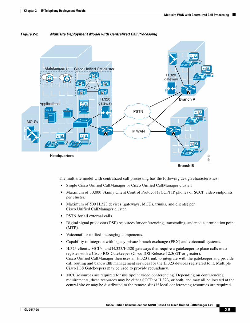
Multisite WAN with Centralized Call ProcessingThe multisite WAN model with centralized call processing consists of a single call processing agent that provides services for many sites and uses the IP WAN to transport IP telephony traffic between the sites. The IP WAN also carries call control signaling between the central site and the remote sites. Figure 2-2 illustrates a typical centralized call processing deployment, with a Cisco Unified CallManager cluster as the call processing agent at the central site and an IP WAN with QoS enabled to connect all the sites. The remote sites rely on the centralized Cisco Unified CallManager cluster to handle their call processing. Applications such as voicemail and Interactive Voice Response (IVR) systems are typically centralized as well to reduce the overall costs of administration and maintenance.
Note In each solution for the centralized call processing model presented in this document, the various sites connect to an IP WAN with QoS enabled.
2-4Cisco Unified Communications SRND (Based on Cisco Unified CallManager 4.x)
OL-7447-06
Chapter 2 IP Telephony Deployment ModelsMultisite WAN with Centralized Call Processing
Figure 2-2 Multisite Deployment Model with Centralized Call Processing
The multisite model with centralized call processing has the following design characteristics:
• Single Cisco Unified CallManager or Cisco Unified CallManager cluster.
• Maximum of 30,000 Skinny Client Control Protocol (SCCP) IP phones or SCCP video endpoints per cluster.
• Maximum of 500 H.323 devices (gateways, MCUs, trunks, and clients) per Cisco Unified CallManager cluster.
• PSTN for all external calls.
• Digital signal processor (DSP) resources for conferencing, transcoding, and media termination point (MTP).
• Voicemail or unified messaging components.
• Capability to integrate with legacy private branch exchange (PBX) and voicemail systems.
• H.323 clients, MCUs, and H.323/H.320 gateways that require a gatekeeper to place calls must register with a Cisco IOS Gatekeeper (Cisco IOS Release 12.3(8)T or greater). Cisco Unified CallManager then uses an H.323 trunk to integrate with the gatekeeper and provide call routing and bandwidth management services for the H.323 devices registered to it. Multiple Cisco IOS Gatekeepers may be used to provide redundancy.
• MCU resources are required for multipoint video conferencing. Depending on conferencing requirements, these resources may be either SCCP or H.323, or both, and may all be located at the central site or may be distributed to the remote sites if local conferencing resources are required.
IP
H.320gateway
Cisco Unified CM cluster
IP
M
M
M M
M
MCU's
Applications
1194
60
IP WAN
PSTN
IP
IP
IP
IP
H.320gateway
Branch A
Branch B
Headquarters
V V
V
Gatekeeper(s)
2-5Cisco Unified Communications SRND (Based on Cisco Unified CallManager 4.x)
OL-7447-06

Chapter 2 IP Telephony Deployment ModelsMultisite WAN with Centralized Call Processing
• H.323/H.320 video gateways are needed to communicate with H.320 videoconferencing devices on the public ISDN network. These gateways may all be located at the central site or may be distributed to the remote sites if local ISDN access is required.
• High-bandwidth audio (for example, G.711, G.722, or Cisco Wideband Audio) between devices in the same site, and low-bandwidth audio (for example, G.729 or G.728) between devices in different sites.
• High-bandwidth video (for example, 384 kbps or greater) between devices in the same site, and low-bandwidth video (for example, 128 kbps) between devices at different sites. The Cisco Unified Video Advantage Wideband Codec, operating at 7 Mbps, is recommended only for calls between devices at the same site.
• Minimum of 768 kbps or greater WAN link speeds. Video is not recommended on WAN connections that operate at speeds lower than 768 kbps.
• Cisco Unified CallManager locations provide call admission control, and automated alternate routing (AAR) is also supported for video calls.
• Maximum of 500 locations per Cisco Unified CallManager cluster.
• Survivable Remote Site Telephony (SRST) is not supported for video. If the WAN connection fails, SCCP video endpoints located at the remote sites become audio-only devices, and H.323 video devices fail. An active SCCP video call between two devices at remote sites will continue with both video and audio channels, but it will not be able to activate additional features such as call transfer. Active H.323 video calls fail. In SRST mode, new calls are always audio-only. Any call that goes over the WAN will be dropped if the WAN connection fails.
Connectivity options for the IP WAN include:
• Leased lines
• Frame Relay
• Asynchronous Transfer Mode (ATM)
• ATM and Frame Relay Service Inter-Working (SIW)
• Multiprotocol Label Switching (MPLS) Virtual Private Network (VPN)
• Voice and Video Enabled IP Security Protocol (IPSec) VPN (V3PN)
Routers that reside at the WAN edges require quality of service (QoS) mechanisms, such as priority queuing and traffic shaping, to protect the voice traffic from the data traffic across the WAN, where bandwidth is typically scarce. In addition, a call admission control scheme is needed to avoid oversubscribing the WAN links with voice traffic and deteriorating the quality of established calls. For centralized call processing deployments, the locations construct within Cisco Unified CallManager provides call admission control. (Refer to the section on Cisco Unified CallManager Static Locations, page 9-12, for more information on locations.)
A variety of Cisco gateways can provide the remote sites with PSTN access. When the IP WAN is down, or if all the available bandwidth on the IP WAN has been consumed, users at the remote sites can dial the PSTN access code and place their calls through the PSTN. The Survivable Remote Site Telephony (SRST) feature on Cisco IOS gateways provides call processing at the branch offices in the event of a WAN failure.
2-6Cisco Unified Communications SRND (Based on Cisco Unified CallManager 4.x)
OL-7447-06
Chapter 2 IP Telephony Deployment ModelsMultisite WAN with Centralized Call Processing
Best Practices for the Centralized Call Processing ModelFollow these guidelines and best practices when implementing the multisite WAN model with centralized call processing:
• Minimize delay between Cisco Unified CallManager and remote locations to reduce voice cut-through delays (also known as clipping).
• Use the locations mechanism in Cisco Unified CallManager to provide call admission control into and out of remote branches. See the chapter on Call Admission Control, page 9-1, for details on how to apply this mechanism to the various WAN topologies.
• The locations mechanism works across multiple servers in Cisco Unified CallManager Release 3.1 and later. This configuration can support a maximum of 30,000 IP phones when Cisco Unified CallManager runs on the largest supported server.
• The number of IP phones and line appearances supported in Survivable Remote Site Telephony (SRST) mode at each remote site depends on the branch router platform, the amount of memory installed, and the Cisco IOS release. (For the latest SRST platform and code specifications, refer to the SRST documentation at Cisco.com.) Generally speaking, however, the choice of whether to adopt a centralized call processing or distributed call processing approach for a given site depends on a number of factors such as:
– IP WAN bandwidth or delay limitations
– Criticality of the voice network
– Feature set needs
– Scalability
– Ease of management
– Cost
If a distributed call processing model is deemed more suitable for the customer's business needs, the choices include installing a local Cisco Unified CallManager server or running Cisco Unified CallManager Express on the branch router.
2-7Cisco Unified Communications SRND (Based on Cisco Unified CallManager 4.x)
OL-7447-06
Chapter 2 IP Telephony Deployment ModelsMultisite WAN with Centralized Call Processing
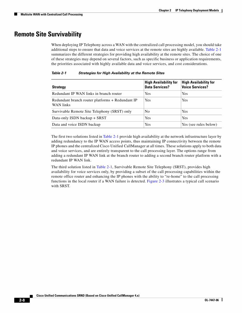
Remote Site SurvivabilityWhen deploying IP Telephony across a WAN with the centralized call processing model, you should take additional steps to ensure that data and voice services at the remote sites are highly available. Table 2-1 summarizes the different strategies for providing high availability at the remote sites. The choice of one of these strategies may depend on several factors, such as specific business or application requirements, the priorities associated with highly available data and voice services, and cost considerations.
The first two solutions listed in Table 2-1 provide high availability at the network infrastructure layer by adding redundancy to the IP WAN access points, thus maintaining IP connectivity between the remote IP phones and the centralized Cisco Unified CallManager at all times. These solutions apply to both data and voice services, and are entirely transparent to the call processing layer. The options range from adding a redundant IP WAN link at the branch router to adding a second branch router platform with a redundant IP WAN link.
The third solution listed in Table 2-1, Survivable Remote Site Telephony (SRST), provides high availability for voice services only, by providing a subset of the call processing capabilities within the remote office router and enhancing the IP phones with the ability to “re-home” to the call processing functions in the local router if a WAN failure is detected. Figure 2-3 illustrates a typical call scenario with SRST.
Table 2-1 Strategies for High Availability at the Remote Sites
StrategyHigh Availability for Data Services?
High Availability for Voice Services?
Redundant IP WAN links in branch router Yes Yes
Redundant branch router platforms + Redundant IP WAN links
Yes Yes
Survivable Remote Site Telephony (SRST) only No Yes
Data-only ISDN backup + SRST Yes Yes
Data and voice ISDN backup Yes Yes (see rules below)
2-8Cisco Unified Communications SRND (Based on Cisco Unified CallManager 4.x)
OL-7447-06
Chapter 2 IP Telephony Deployment ModelsMultisite WAN with Centralized Call Processing
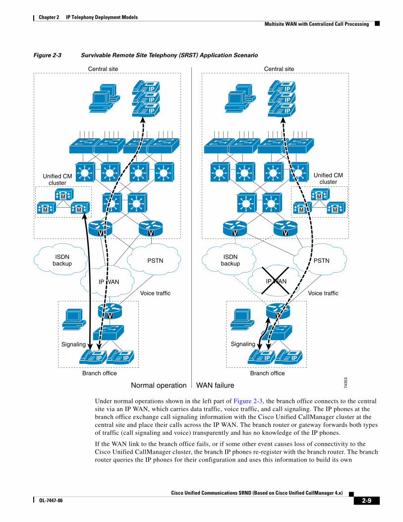
Figure 2-3 Survivable Remote Site Telephony (SRST) Application Scenario
Under normal operations shown in the left part of Figure 2-3, the branch office connects to the central site via an IP WAN, which carries data traffic, voice traffic, and call signaling. The IP phones at the branch office exchange call signaling information with the Cisco Unified CallManager cluster at the central site and place their calls across the IP WAN. The branch router or gateway forwards both types of traffic (call signaling and voice) transparently and has no knowledge of the IP phones.
If the WAN link to the branch office fails, or if some other event causes loss of connectivity to the Cisco Unified CallManager cluster, the branch IP phones re-register with the branch router. The branch router queries the IP phones for their configuration and uses this information to build its own
IP
IP
IP
M
M M
V V
V
Central site
Unified CMcluster
Branch office Branch office
Normal operation WAN failure
Unified CMcluster
Central site
ISDNbackup
IP WAN
PSTN
Voice traffic
Signaling Signaling
Voice traffic
IP IP
IP
IP
IP
V
IP IP
M
M M
V V
ISDNbackup
IP WAN
PSTN
7435
3
2-9Cisco Unified Communications SRND (Based on Cisco Unified CallManager 4.x)
OL-7447-06
Chapter 2 IP Telephony Deployment ModelsMultisite WAN with Centralized Call Processing
configuration automatically. The branch IP phones can then make and receive calls either internally or through the PSTN. The phone displays the message “Unified CM fallback mode,” and some advanced Cisco Unified CallManager features are unavailable and are grayed out on the phone display.
When WAN connectivity to the central site is reestablished, the branch IP phones automatically re-register with the Cisco Unified CallManager cluster and resume normal operation. The branch router deletes its information about the IP phones and reverts to its standard routing or gateway configuration.
The last two solutions in Table 2-1 use an ISDN backup link to provide survivability during WAN failures. The two deployment options for ISDN backup are:
• Data-only ISDN backup
With this option, ISDN is used for data survivability only, while SRST is used for voice survivability. Note that you should configure an access control list on the branch router to prevent Skinny Client Control Protocol (SCCP) traffic from entering the ISDN interface, so that signaling from the IP phones does not reach the Cisco Unified CallManager at the central site.
• Data and voice ISDN backup
With this option, ISDN is used for both data and voice survivability. In this case, SRST is not used because the IP phones maintain IP connectivity to the Cisco Unified CallManager cluster at all times. However, Cisco recommends that you use ISDN to transport data and voice traffic only if all of the following conditions are true:
– The bandwidth allocated to voice traffic on the ISDN link is the same as the bandwidth allocated to voice traffic on the IP WAN link.
– The ISDN link bandwidth is fixed.
– All the required QoS features have been deployed on the router's ISDN interfaces. Refer to the chapter on Network Infrastructure, page 3-1, for more details on QoS.
Voice Over the PSTN as a Variant of Centralized Call ProcessingThe centralized call processing deployment model can be adapted so that inter-site voice media is sent over the PSTN instead of the WAN. With this configuration, the signaling (call control) of all telephony endpoints is still controlled by the central Cisco Unified CallManager cluster, therefore this Voice over the PSTN (VoPSTN) model variation still requires a QoS-enabled WAN with appropriate bandwidth configured for the signaling traffic.
You can implement VoPSTN in one of the following ways:
• Using the automated alternate routing (AAR) feature. (For more information on AAR, see the section on Automated Alternate Routing, page 10-22.)
• Using a combination of dial plan constructs in both Cisco Unified CallManager and the PSTN gateways.
VoPSTN can be an attractive option in deployments where IP WAN bandwidth is either scarce or expensive with respect to PSTN charges, or where IP WAN bandwidth upgrades are planned for a later date but the IP telephony system is already being deployed.
Note Because of its very nature, the VoPSTN deployment model variation offers basic voice functionality that is a reduced subset of the Cisco Unified CallManager feature set.
2-10Cisco Unified Communications SRND (Based on Cisco Unified CallManager 4.x)
OL-7447-06

Chapter 2 IP Telephony Deployment ModelsMultisite WAN with Centralized Call Processing
In particular, regardless of the implementation choice, the system designer should address the following issues, among others:
• Centralized voicemail requires:
– A telephony network provider that supports redirected dialed number identification service (RDNIS) end-to-end for all locations that are part of the deployment. RDNIS is required so that calls redirected to voicemail carry the redirecting DN, to ensure proper voicemail box selection.
– If the voicemail system is accessed through an MGCP gateway, the voicemail pilot number must be a fully qualified E.164 number.
• The Extension Mobility feature is limited to IP phones contained within a single branch site.
• All on-net (intra-cluster) calls will be delivered to the destination phone with the same call treatment as an off-net (PSTN) call. This includes the quantity of digits delivered in the call directories such as Missed Calls and Received Calls.
• Each inter-branch call generates two independent call detail records (CDRs): one for the call leg from the calling phone to the PSTN, and the other for the call leg from the PSTN to the called phone.
• There is no way to distinguish the ring type for on-net and off-net calls.
• All destination phones require a fully qualified Direct Inward Dial (DID) PSTN number that can be called directly. Non-DID DNs cannot be reached directly from a different branch site.
• With VoPSTN, music on hold (MoH) is limited to cases where the holding party is co-located with the MoH resource. If MoH servers are deployed at the central site, then only calls placed on hold by devices at the central site will receive the hold music.
• Transfers to a destination outside the branch site will result in the hairpinning of the call through the branch's gateway. Traffic engineering of the branch's gateway resources must be adjusted accordingly.
• Call forwarding of any call coming into the branch's gateway to a destination outside the branch site will result in hairpinning of the call through the gateway, thus using two trunk ports. This behavior applies to:
– Calls forwarded to a voicemail system located outside the branch
– Calls forwarded to an on-net abbreviated dialing destination located in a different branch
The gateway port utilization resulting from these call forwarding flows should be taken into account when sizing the trunks connecting the branch to the PSTN.
• Conferencing resources must be co-located with the phone initiating the conference.
• VoPSTN does not support applications that require streaming of IP audio from the central site (that is, not traversing a gateway). These applications include, but are not limited to:
– Centralized music on hold (MoH) servers
– Interactive Voice Response (IVR)
– CTI-based applications
• Use of the Attendant Console outside of the central site can require a considerable amount of bandwidth if the remote sites must access large user account directories without caching them.
• Because all inter-branch media (including transfers) are sent through the PSTN, the gateway trunk group must be sized to accommodate all inter-branch traffic, transfers, and centralized voicemail access.
• Cisco recommends that you do not deploy shared lines across branches, such that the devices sharing the line are in different branches.
2-11Cisco Unified Communications SRND (Based on Cisco Unified CallManager 4.x)
OL-7447-06
Chapter 2 IP Telephony Deployment ModelsMultisite WAN with Centralized Call Processing
In addition to these general considerations, the following sections present recommendations and issues specific to each of the following implementation methods:
• VoPSTN Using AAR, page 2-12
• VoPSTN Using Dial Plan, page 2-13
VoPSTN Using AAR
This method consists of configuring the Cisco Unified CallManager dial plan as in a traditional centralized call processing deployment, with the automated alternate routing (AAR) feature also properly configured. AAR provides transparent re-routing over the PSTN of inter-site calls when the locations mechanism for call admission control determines that there is not enough available WAN bandwidth to accept an additional call.
To use the PSTN as the primary (and only) voice path, you can configure the call admission control bandwidth of each location (branch site) to be 1 kbps, thus preventing all calls from traversing the WAN. With this configuration, all inter-site calls trigger the AAR functionality, which automatically re-routes the calls over the PSTN.
The AAR implementation method for VoPSTN offers the following benefits:
• An easy migration path to a complete IP telephony deployment. When bandwidth becomes available to support voice media over the WAN, the dial plan can be maintained intact, and the only change needed is to update the location bandwidth value for each site.
• Support for some supplementary features, such as callback on busy.
In addition to the general considerations listed for VoPSTN, the following design guidelines apply to the AAR implementation method:
• AAR functionality must be configured properly.
• As a general rule, supported call initiation devices include IP phones, gateways, and line-side gateway-driven analog phones.
• Inter-branch calls can use AAR only if the destination devices are IP phones or Cisco Unity ports.
• Inter-branch calls to other endpoints must use a fully qualified E.164 number.
• All on-net, inter-branch calls will display the message, "Network congestion, rerouting."
• If destination phones become unregistered (for example, due to WAN connectivity interruption), AAR functionality will not be invoked and abbreviated dialing will not be possible. If the destination phone has registered with an SRST router, then it can be reached by directly dialing its PSTN DID number.
• If originating phones become unregistered (for example, due to WAN connectivity interruption), they will go into SRST mode. To preserve abbreviated dialing functionality under these conditions, configure the SRST router with an appropriate set of translation rules.
• Shared lines within the same branch should be configured in a partition included only in that branch's calling search spaces. Inter-site access to the shared line requires one of the following:
– The originating site dials the DID number of the shared line.
– If inter-site abbreviated dialing to the shared line is desired, use a translation pattern that expands the user-dialed abbreviated string to the DID number of the shared line.
Note In this case, direct dialing of the shared line's DN from another branch would trigger multiple AAR-based PSTN calls.
2-12Cisco Unified Communications SRND (Based on Cisco Unified CallManager 4.x)
OL-7447-06
Chapter 2 IP Telephony Deployment ModelsMultisite WAN with Centralized Call Processing
VoPSTN Using Dial Plan
This method relies on a specific dial plan configuration within Cisco Unified CallManager and the PSTN gateways to route all inter-site calls over the PSTN. The dial plan must place IP phone DN's at each site into a different partition, and their calling search space must provide access only to the site's internal partition and a set of route patterns that point to the local PSTN gateway.
Abbreviated inter-site dialing can still be provided via a set of translations at each branch site, one for each of the other branch sites. These translations are best accomplished with H.323 gateways and translation rules within Cisco IOS.
The dial plan method for implementing VoPSTN offers the following benefits:
• Easier configuration because AAR is not needed.
• Abbreviated dialing automatically works even under WAN failure conditions on either the originating or destination side, because the Cisco IOS translation rules within the H.323 gateway are effective in SRST mode.
In addition to the general considerations listed for VoPSTN, the following design guidelines apply to the dial plan implementation method:
• There is no support for supplementary features such as callback on busy.
• Some CTI-based applications do not support overlapping extensions (that is, two or more phones configured with the same DN, although in different partitions).
• There is no easy migration to a complete IP telephony deployment because the dial plan needs to be redesigned.
2-13Cisco Unified Communications SRND (Based on Cisco Unified CallManager 4.x)
OL-7447-06

Chapter 2 IP Telephony Deployment ModelsMultisite WAN with Distributed Call Processing
Multisite WAN with Distributed Call ProcessingThe multisite WAN model with distributed call processing consists of multiple independent sites, each with its own call processing agent connected to an IP WAN that carries voice traffic between the distributed sites. Figure 2-4 illustrates a typical distributed call processing deployment.
Figure 2-4 Multisite Deployment Model with Distributed Call Processing
Each site in the distributed call processing model can be one of the following:
• A single site with its own call processing agent, which can be either:
– Cisco Unified CallManager
– Cisco Unified CallManager Express
– Other IP PBX
• A centralized call processing site and all of its associated remote sites
• A legacy PBX with Voice over IP (VoIP) gateway
IP
H.320gateway
ISDNnetwork
Cisco Unified CMcluster
IP
M
M
M M
M
MediaResources
MediaResources
MediaResources
Applications
Applications
Applications
1418
51
IP WAN
M
M
M M
M
IP
IP
M
M
M M
M
IPIP
H.320gateway
H.320gateway
Branch A
Branch B
HeadquartersPSTN
V
VV
Gatekeeper(s)
2-14Cisco Unified Communications SRND (Based on Cisco Unified CallManager 4.x)
OL-7447-06

Chapter 2 IP Telephony Deployment ModelsMultisite WAN with Distributed Call Processing
The multisite model with distributed call processing has the following design characteristics:
• Maximum of 30,000 Skinny Client Control Protocol (SCCP) IP phones or SCCP video endpoints per cluster.
• Maximum of 500 H.323 devices (gateways, MCUs, trunks, and clients) per Cisco Unified CallManager cluster.
• PSTN for all external calls.
• Digital signal processor (DSP) resources for conferencing, transcoding, and media termination point (MTP).
• Voicemail or unified messaging components.
• Capability to integrate with legacy private branch exchange (PBX) and voicemail systems.
• H.323 clients, MCUs, and H.323/H.320 gateways that require a gatekeeper to place calls must register with a Cisco IOS Gatekeeper (Cisco IOS Release 12.3(8)T or greater). Cisco Unified CallManager then uses an H.323 trunk to integrate with the gatekeeper and provide call routing and bandwidth management services for the H.323 devices registered to it. Multiple Cisco IOS Gatekeepers may be used to provide redundancy. Cisco IOS Gatekeepers may also be used to provide call routing and bandwidth management between the distributed Cisco Unified CallManager clusters. In most situations, Cisco recommends that each Cisco Unified CallManager cluster have its own set of endpoint gatekeepers and that a separate set of gatekeepers be used to manage the intercluster calls. It is possible in some circumstances to use the same set of gatekeepers for both functions, depending on the size of the network, complexity of the dial plan, and so forth. (For details, see Gatekeepers, page 17-19.)
• MCU resources are required in each cluster for multipoint video conferencing. Depending on conferencing requirements, these resources may be either SCCP or H.323, or both, and may all be located at the regional sites or may be distributed to the remote sites of each cluster if local conferencing resources are required.
• H.323/H.320 video gateways are needed to communicate with H.320 videoconferencing devices on the public ISDN network. These gateways may all be located at the regional sites or may be distributed to the remote sites of each cluster if local ISDN access is required.
• High-bandwidth audio (for example, G.711, G.722, or Cisco Wideband Audio) between devices in the same site, but low-bandwidth audio (for example, G.729 or G.728) between devices in different sites.
• High-bandwidth video (for example, 384 kbps or greater) between devices in the same site, but low-bandwidth video (for example, 128 kbps) between devices at different sites. The Cisco Unified Video Advantage Wideband Codec, operating at 7 Mbps, is recommended only for calls between devices at the same site. Note that the Cisco VT Camera Wideband Video Codec is not supported over intercluster trunks.
• Minimum of 768 kbps or greater WAN link speeds. Video is not recommended on WAN connections that operate at speeds lower than 768 kbps.
• Call admission control is provided by Cisco Unified CallManager locations for calls between sites controlled by the same Cisco Unified CallManager cluster, and by the Cisco IOS Gatekeeper for calls between Cisco Unified CallManager clusters (that is, intercluster trunks). Automated alternate routing (AAR) is also supported for both intra-cluster and inter-cluster video calls.
An IP WAN interconnects all the distributed call processing sites. Typically, the PSTN serves as a backup connection between the sites in case the IP WAN connection fails or does not have any more available bandwidth. A site connected only through the PSTN is a standalone site and is not covered by the distributed call processing model. (See Single Site, page 2-2.)
2-15Cisco Unified Communications SRND (Based on Cisco Unified CallManager 4.x)
OL-7447-06
Chapter 2 IP Telephony Deployment ModelsMultisite WAN with Distributed Call Processing
Connectivity options for the IP WAN include:
• Leased lines
• Frame Relay
• Asynchronous Transfer Mode (ATM)
• ATM and Frame Relay Service Inter-Working (SIW)
• Multiprotocol Label Switching (MPLS) Virtual Private Network (VPN)
• Voice and Video Enabled IP Security Protocol (IPSec) VPN (V3PN)
Benefits of the Distributed Call Processing ModelThe multisite WAN model with distributed call processing provides the following benefits:
• PSTN call cost savings when using the IP WAN for calls between sites.
• Use of the IP WAN to bypass toll charges by routing calls through remote site gateways, closer to the PSTN number dialed. This practice is known as tail-end hop-off (TEHO).
• Maximum utilization of available bandwidth by allowing voice traffic to share the IP WAN with other types of traffic.
• No loss of functionality during IP WAN failure because there is a call processing agent at each site.
• Scalability to hundreds of sites.
Best Practices for the Distributed Call Processing ModelA multisite WAN deployment with distributed call processing has many of the same requirements as a single site or a multisite WAN deployment with centralized call processing. Follow the best practices from these other models in addition to the ones listed here for the distributed call processing model. (See Single Site, page 2-2, and Multisite WAN with Centralized Call Processing, page 2-4.)
Gatekeeper or Session Initiation Protocol (SIP) proxy servers are among the key elements in the multisite WAN model with distributed call processing. They each provide dial plan resolution, with the gatekeeper also providing call admission control. A gatekeeper is an H.323 device that provides call admission control and E.164 dial plan resolution.
The following best practices apply to the use of a gatekeeper:
• Use a Cisco IOS gatekeeper to provide call admission control into and out of each site.
• To provide high availability of the gatekeeper, use Hot Standby Router Protocol (HSRP) gatekeeper pairs, gatekeeper clustering, and alternate gatekeeper support. In addition, use multiple gatekeepers to provide redundancy within the network. (See Gatekeeper Design Considerations, page 8-18.)
• Size the platforms appropriately to ensure that performance and capacity requirements can be met.
• Use only one type of codec on the WAN because the H.323 specification does not allow for Layer 2, IP, User Data Protocol (UDP), or Real-time Transport Protocol (RTP) header overhead in the bandwidth request. (Header overhead is allowed only in the payload or encoded voice part of the packet.) Using one type of codec on the WAN simplifies capacity planning by eliminating the need to over-provision the IP WAN to allow for the worst-case scenario.
• Gatekeeper networks can scale to hundreds of sites, and the design is limited only by the WAN topology.
2-16Cisco Unified Communications SRND (Based on Cisco Unified CallManager 4.x)
OL-7447-06
Chapter 2 IP Telephony Deployment ModelsClustering Over the IP WAN
For more information on the various functions performed by gatekeepers, refer to the following sections:
• For gatekeeper call admission control, see Call Admission Control, page 9-1.
• For gatekeeper scalability and redundancy, see Call Processing, page 8-1.
• For gatekeeper dial plan resolution, see Dial Plan, page 10-1.
SIP devices provide resolution of E.164 numbers as well as SIP uniform resource identifiers (URIs) to enable endpoints to place calls to each other. Cisco Unified CallManager supports the use of E.164 numbers only.
The following best practices apply to the use of SIP proxies:
• Provide adequate redundancy for the SIP proxies.
• Ensure that the SIP proxies have the capacity for the call rate and number of calls required in the network.
• Planning for call admission control is outside the scope of this document.
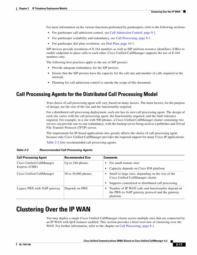
Call Processing Agents for the Distributed Call Processing ModelYour choice of call processing agent will vary, based on many factors. The main factors, for the purpose of design, are the size of the site and the functionality required.
For a distributed call processing deployment, each site has its own call processing agent. The design of each site varies with the call processing agent, the functionality required, and the fault tolerance required. For example, in a site with 500 phones, a Cisco Unified CallManager cluster containing two servers can provide one-to-one redundancy, with the backup server being used as a publisher and Trivial File Transfer Protocol (TFTP) server.
The requirement for IP-based applications also greatly affects the choice of call processing agent because only Cisco Unified CallManager provides the required support for many Cisco IP applications.
Table 2-2 lists recommended call processing agents.
Clustering Over the IP WANYou may deploy a single Cisco Unified CallManager cluster across multiple sites that are connected by an IP WAN with QoS features enabled. This section provides a brief overview of clustering over the WAN. For further information, refer to the chapter on Call Processing, page 8-1.
Table 2-2 Recommended Call Processing Agents
Call Processing Agent Recommended Size Comments
Cisco Unified CallManager Express (CME)
Up to 240 phones • For small remote sites
• Capacity depends on Cisco IOS platform
Cisco Unified CallManager 50 to 30,000 phones • Small to large sites, depending on the size of the Cisco Unified CallManager cluster
• Supports centralized or distributed call processing
Legacy PBX with VoIP gateway Depends on PBX • Number of IP WAN calls and functionality depend on the PBX-to-VoIP gateway protocol and the gateway platform
2-17Cisco Unified Communications SRND (Based on Cisco Unified CallManager 4.x)
OL-7447-06

Chapter 2 IP Telephony Deployment ModelsClustering Over the IP WAN
Clustering over the WAN can support two types of deployments:
• Local Failover Deployment Model, page 2-22
Local failover requires that you place the Cisco Unified CallManager subscriber and backup servers at the same site, with no WAN between them. This deployment model is ideal for two to four sites with Cisco Unified CallManager
• Remote Failover Deployment Model, page 2-26
Remote failover allows you to deploy the backup servers over the WAN. Using this deployment model, you may have up to eight sites with Cisco Unified CallManager subscribers being backed up by Cisco Unified CallManager subscribers at another site.
You can also use a combination of the two deployment models to satisfy specific site requirements. For example, two main sites may each have primary and backup subscribers, with another two sites containing only a primary server each and utilizing either shared backups or dedicated backups at the two main sites.
The key advantages of clustering over the WAN are:
• Single point of administration for users for all sites within the cluster
• Feature transparency
• Shared line appearances
• Extension mobility within the cluster
• Unified dial plan
These features make this solution ideal as a disaster recovery plan for business continuance sites or as a single solution for up to eight small or medium sites.
WAN ConsiderationsFor clustering over the WAN to be successful, you must carefully plan, design, and implement various characteristics of the WAN itself. The Intra-Cluster Communication Signaling (ICCS) between Cisco Unified CallManager servers consists of many traffic types. The ICCS traffic types are classified as either priority or best-effort. Priority ICCS traffic is marked with IP Precedence 3 (DSCP 24 or PHB CS3). Best-effort ICCS traffic is marked with IP Precedence 0 (DSCP 0 or PHB BE). The various types of ICCS traffic are described in Intra-Cluster Communications, page 2-19, which also provides further guidelines for provisioning. The following design guidelines apply to the indicated WAN characteristics:
• Delay
The maximum one-way delay between any Cisco Unified CallManager servers for all priority ICCS traffic should not exceed 20 ms, or 40 ms round-trip time (RTT). Delay for other ICCS traffic should be kept reasonable to provide timely database and directory access. Measuring the delay is covered in Delay Testing, page 2-20. Propagation delay between two sites introduces 6 microseconds per kilometer without any other network delays being considered. This equates to a theoretical maximum distance of approximately 3000 km for 20 ms delay or approximately 1860 miles. These distances are provided only as relative guidelines and in reality will be shorter due to other delay incurred within the network.
• Jitter
Jitter is the varying delay that packets incur through the network due to processing, queue, buffer, congestion, or path variation delay. Jitter for the IP Precedence 3 ICCS traffic must be minimized using Quality of Service (QoS) features.
2-18Cisco Unified Communications SRND (Based on Cisco Unified CallManager 4.x)
OL-7447-06
Chapter 2 IP Telephony Deployment ModelsClustering Over the IP WAN
• Packet loss and errors
The network should be engineered to provide sufficient prioritized bandwidth for all ICCS traffic, especially the priority ICCS traffic. Standard QoS mechanisms must be implemented to avoid congestion and packet loss. If packets are lost due to line errors or other “real world” conditions, the ICCS packet will be retransmitted because it uses the TCP protocol for reliable transmission. The retransmission might result in a call being delayed during setup, disconnect (teardown), or other supplementary services during the call. Some packet loss conditions could result in a lost call, but this scenario should be no more likely than errors occurring on a T1 or E1, which affect calls via a trunk to the PSTN/ISDN.
• Bandwidth
Provision the correct amount of bandwidth between each server for the expected call volume, type of devices, and number of devices. This bandwidth is in addition to any other bandwidth for other applications sharing the network, including voice and video traffic between the sites. The bandwidth provisioned must have QoS enabled to provide the prioritization and scheduling for the different classes of traffic. The general rule of thumb for bandwidth is to over-provision and under-subscribe.
• Quality of Service
The network infrastructure relies on QoS engineering to provide consistent and predictable end-to-end levels of service for traffic. Neither QoS nor bandwidth alone is the solution; rather, QoS-enabled bandwidth must be engineered into the network infrastructure.
Intra-Cluster CommunicationsIn general, intra-cluster communications means all traffic between servers. There is also a real-time protocol called Intra-Cluster Communication Signaling (ICCS), which provides the communications with the Cisco CallManager Service process that is at the heart of the call processing in each server or node within the cluster.
The intra-cluster traffic between the servers consists of the following:
• Database traffic from the MS-SQL database that provides the main configuration information. The SQL database is replicated from the publisher server to all other servers in the cluster using best-effort. The SQL traffic may be re-prioritized in line with Cisco QoS recommendations to a higher priority data service (for example, IP Precedence 1 if required by the particular business needs). An example of this is extensive use of Extension Mobility, which relies on SQL database configuration.
• ICCS real-time traffic, which consists of signaling, call admission control, and other information regarding calls as they are initiated and completed. ICCS uses a Transmission Control Protocol (TCP) connection between all servers that have the Cisco CallManager Service enabled. The connections are a full mesh between these servers. Because only eight servers may have the Cisco CallManager Service enabled in a cluster, there may be up to seven connections on each server. This traffic is priority ICCS traffic and is marked dependant on release and service parameter configuration.
• CTI Manager real-time traffic is used for CTI devices involved in calls or for controlling or monitoring other third-party devices on the Cisco Unified CallManager servers. This traffic is marked as priority ICCS traffic and exists between the Cisco Unified CallManager server with the CTI Manager and the Cisco Unified CallManager server with the CTI device.
2-19Cisco Unified Communications SRND (Based on Cisco Unified CallManager 4.x)
OL-7447-06
Chapter 2 IP Telephony Deployment ModelsClustering Over the IP WAN
Failover Between Subscriber Servers
With Cisco Unified CallManager Release 4.2, the device configuration records are cached during the initialization or boot-up time. The effect is that Cisco Unified CallManager might take a longer time to initialize, but any failover or failback for all devices is not affected by the delay in accessing the publisher database.
Cisco Unified CallManager Publisher
The publisher replicates a read-only copy of the master database to all other servers in the cluster. If changes are made in the publisher’s master database during a period when another server in the cluster is unreachable, the publisher will replicate the updated database when communications are re-established. During any period when the publisher is unreachable or offline, no changes can be made to the configuration database. All subscriber databases are read-only and may not be modified. Most normal operations of the cluster will not be affected during this period, including the following:
• Call processing
• Failover
• Installation registration of previously configured devices
There are some features and functions that require access to the master database on the publisher because they make modifications to records and therefore need write access. The publisher is the only server in a Cisco Unified CallManager cluster that has a read and write configuration database. The main features and functions that require access to the publisher for write access include:
• Configuration additions, changes, and deletions
• Extension Mobility and Device Mobility
• User speed dials
• Cisco Unified CallManager User page options requiring the database
• Cisco Unified CallManager software upgrades
• Call Forward All changes
• Message Waiting Indicator (MWI) state
Other services or applications might also be affected, and their ability to function without the publisher should be verified when deployed.
Call Detail Records (CDR)
Call detail records, when enabled, are collected by each subscriber and uploaded to the publisher periodically. During a period that the publisher is unreachable, the CDRs are stored on the subscriber’s local hard disk. When connectivity is re-established to the publisher, all outstanding CDRs are uploaded to the publisher.
Delay Testing
The maximum round-trip time (RTT) between any two servers must not exceed 40 ms at any time. This time limit must include all delays in the transmission path between the two servers. Verifying the round trip delay using the ping utility on the Cisco Unified CallManager server will not provide an accurate result. The ping is sent as a best-effort tagged packet and is not transported using the same QoS-enabled path as the ICCS traffic. Therefore, Cisco recommends that you verify the delay by using the closest
2-20Cisco Unified Communications SRND (Based on Cisco Unified CallManager 4.x)
OL-7447-06
Chapter 2 IP Telephony Deployment ModelsClustering Over the IP WAN
network device to the Cisco Unified CallManager servers, ideally the access switch to which the server is attached. Cisco IOS provides a extended ping capable to set the Layer 3 type of service (ToS) bits to make sure the ping packet is sent on the same QoS-enabled path that the ICCS traffic will traverse. The time recorded by the extended ping is the round-trip time (RTT), or the time it takes to traverse the communications path and return. The maximum RTT between any two Cisco Unified CallManager servers is 40 ms, and therefore the maximum one-way delay would be 20 ms. This delay is critical to the performance of the call processing capabilities of the Cisco Unified CallManager cluster and must be strictly enforced.
The following example shows a Cisco IOS extended ping with the ToS bit (IP Precedence) set to 3:
Access_SW#pingProtocol [ip]:Target IP address: 10.10.10.10Repeat count [5]:Datagram size [100]:Timeout in seconds [2]:Extended commands [n]: ySource address or interface:Type of service [0]: 3Set DF bit in IP header? [no]:Validate reply data? [no]:Data pattern [0xABCD]:Loose, Strict, Record, Timestamp, Verbose[none]:Sweep range of sizes [n]:Type escape sequence to abort.Sending 5, 100-byte Intelligent Contact ManagementP Echos to 10.10.10.10, timeout is 2 seconds:!!!!!Success rate is 100 percent (5/5), round-trip min/avg/max = 1/2/4 ms
Error Rate
The expected error rate should be zero. Any errors, dropped packets, or other impairments to the IP network can have an impact to the call processing performance of the cluster. This may be noticeable by delay in dial tone, slow key or display response on the IP phone, or delay from off-hook to connection of the voice path. Although Cisco Unified CallManager will tolerate random errors, they should be avoided to avoid impairing the performance of the cluster.
Troubleshooting
If the Cisco Unified CallManager subscribers in a cluster are experiencing impairment of the ICCS communication due to higher than expected delay, errors, or dropped packets, some of the following symptoms might occur:
• IP phones, gateways, or other devices on a remote Cisco Unified CallManager server within the cluster might temporarily be unreachable.
• Calls might be disconnected or might fail during call setup.
• Users might experience longer than expected delays before hearing dial tone.
• Busy hour call completions (BHCC) might be low.
2-21Cisco Unified Communications SRND (Based on Cisco Unified CallManager 4.x)
OL-7447-06

Chapter 2 IP Telephony Deployment ModelsClustering Over the IP WAN
• The ICCS (SDL session) might be reset or disconnected. The following example shows a Cisco Unified CallManager SDL trace of a remote server VO30-7835-8 going Out of Service and the devices that were reachable by that server being removed as “available” destinations:
RemoteCMOutOfService: Ip address: VO30-7835-8 remoteClusterId VO30-7835-1-Cluster|<CLID::VO30-7835-1-Cluster><NID::VO30-7835-2>|Delete entries from SsManagerTable, now this table has 75 entries|<CLID::VO30-7835-1-Cluster><NID::VO30-7835-2><CT::0,0,0,0.0><IP::><DEV::>|Delete entries from FeatActTable, now this table has 70 entries|<CLID::VO30-7835-1-Cluster><NID::VO30-7835-2><CT::0,0,0,0.0><IP::><DEV::>|Digit analysis: Remove remote pattern /5000020 , PID: 7:34:1|<CLID::VO30-7835-1-Cluster><NID::VO30-7835-2><CT::0,0,0,0.0><IP::><DEV::>|Digit analysis: Remove remote pattern /5000066 , PID: 7:34:2|<CLID::VO30-7835-1-Cluster><NID::VO30-7835-2><CT::0,0,0,0.0><IP::><DEV::>...|Digit analysis: Remove remote pattern /5001002 , PID: 7:34:106|<CLID::VO30-7835-1-Cluster><NID::VO30-7835-2><CT::0,0,0,0.0><IP::><DEV::>
In summary, perform the following tasks to troubleshoot ICCS communication problems:
• Verify the delay between the servers.
• Check all links for errors or dropped packets.
• Verify that QoS is correctly configured.
• Verify that sufficient bandwidth is provisioned for the queues and across the WAN to support all the traffic.
Local Failover Deployment ModelThe local failover deployment model provides the most resilience for clustering over the WAN. Each of the sites in this model contains at least one primary Cisco Unified CallManager subscriber and one backup subscriber. This configuration can support up to four sites. The maximum number of phones and other devices will be dependant on the quantity and type of servers deployed. The maximum total number of IP phones for all sites is 30,000. (See Figure 2-5.)
2-22Cisco Unified Communications SRND (Based on Cisco Unified CallManager 4.x)
OL-7447-06

Chapter 2 IP Telephony Deployment ModelsClustering Over the IP WAN
Figure 2-5 Example of Local Failover Model
Observe the following guidelines when implementing the local failover model:
• Configure each site to contain at least one primary Cisco Unified CallManager subscriber and one backup subscriber.
• Configure Cisco Unified CallManager groups and device pools to allow devices within the site to register with only the servers at that site under all conditions.
• Cisco highly recommends that you replicate key services (TFTP, DNS, DHCP, LDAP, and IP Phone Services), all media resources (conference bridges and music on hold), and gateways at each site to provide the highest level of resiliency. You could also extend this practice to include a voicemail system at each site.
• Under a WAN failure condition, sites without access to the publisher database will loose some functionality, as follows:
– System administration at the local site will not be able to add, modify, or delete any part of the configuration.
– Extension mobility users will not be able to log in or log out of the IP phones.
– Changes to Call Forward All will not be allowed.
WANM
M M
M
IP
V
Site A Publisher/TFTP server
Sub A Sub B
Backup
Sub A Sub B
Backup
Site B
Gateway
Voice MailServer MOH
JTAPIIP-AA/IVR
IP Phone
Conf
Xcode
SoftPhone
M
M M
IP
V
Gateway
Voice MailServer MOH
JTAPIIP-AA/IVR
IP Phone
Conf
Xcode
SoftPhone
V V
7436
0
2-23Cisco Unified Communications SRND (Based on Cisco Unified CallManager 4.x)
OL-7447-06

Chapter 2 IP Telephony Deployment ModelsClustering Over the IP WAN
• Under WAN failure conditions, calls made to phone numbers that are not currently communicating with the subscriber placing the call, will result in either a fast-busy tone or a call forward (possibly to voicemail, dependant on the location of the phone number being forwarded to). During this condition, users should manually dial those numbers via the PSTN.
• Every 10,000 busy hour call attempts (BHCA) between sites that are clustered over the WAN requires 900 kbps of bandwidth for Intra-Cluster Communication Signaling (ICCS). This is a minimum bandwidth requirement, and bandwidth is allocated in multiples of 900 kbps. The ICCS traffic types are classified as either priority or best-effort. Priority ICCS traffic is marked with IP Precedence 3 (DSCP 24 or PHB CS3). Best-effort ICCS traffic is marked with IP Precedence 0 (DSCP 0 or PHB BE).
• The minimum recommended bandwidth between sites that are clustered over the WAN is 1.544 Mbps. This amount allows for the minimum of 900 kbps for ICCS and 644 kbps for database and other inter-server traffic.
• A maximum round-trip time (RTT) of 40 ms is allowed between any two servers in the Cisco Unified CallManager cluster. This time equates to a 20 ms maximum one-way delay, or a transmission distance of approximately 1860 miles (3000 km) under ideal conditions.
• If remote branches using centralized call processing are connected to the main sites via clustering over the WAN, pay careful attention to the configuration of call admission control to avoid oversubscribing the links used for clustering over the WAN.
– If the bandwidth is not limited on the links used for clustering over the WAN (that is, if the interfaces to the links are OC-3s or STM-1s and there is no requirement for call admission control), then the remote sites may be connected to any of the main sites because all the main sites should be configured as location <None>. This configuration still maintains hub-and-spoke topology for purposes of call admission control.
– If you are using the Multiprotocol Label Switching (MPLS) Virtual Private Network (VPN) feature, all sites in Cisco Unified CallManager locations and the remote sites may register with any of the main sites.
– If bandwidth is limited between the main sites, call admission control must be used between sites, and all remote sites must register with the main site that is configured as location <None>. This main site is considered the hub site, and all other remote sites and clustering-over-the-WAN sites are spokes sites.
• During a software upgrade, all servers in the cluster should be upgraded during the same maintenance period, using the standard upgrade procedures outlined in the software release notes.
Cisco Unified CallManager Provisioning for Local Failover
Provisioning of the Cisco Unified CallManager cluster for the local failover model should follow the design guidelines for capacities outlined in the chapter on Call Processing, page 8-1. If voice or video calls are allowed across the WAN between the sites, then you must configure Cisco Unified CallManager locations in addition to the default location for the other sites, to provide call admission control between the sites. If the bandwidth is over-provisioned for the number of devices, it is still best practice to configure call admission control based on locations. If the locations-based call admission control rejects a call, automatic failover to the PSTN can be provided by the automated alternate routing (AAR) feature.
To improve redundancy and upgrade times, Cisco recommends that you enable the Cisco Trivial Transfer Protocol (TFTP) service on two Cisco Unified CallManager servers. Cisco also recommends that you do not enable more than one server with the Cisco TFTP service at a location remote to publisher, over a low-speed WAN link. More than two TFTP servers can be deployed in a cluster, however this configuration can result in an extended period for rebuilding all the TFTP files on all TFTP servers.
2-24Cisco Unified Communications SRND (Based on Cisco Unified CallManager 4.x)
OL-7447-06
Chapter 2 IP Telephony Deployment ModelsClustering Over the IP WAN
You can run the TFTP service on either a publisher or a subscriber server, depending on the site and the available capacity of the server. The TFTP server option must be correctly set in the DHCP servers at each site. If DHCP is not in use or if the TFTP server is manually configured, you should configure the correct address for the site. During an upgrade of the cluster or a restart of the Cisco TFTP service, the TFTP servers that are remote from the publisher will take longer to upgrade and rebuild all the configuration files. This time depends on the latency between the TFTP server and the publisher and on the quantity of devices configured in the database.
Other services, which may affect normal operation of Cisco Unified CallManager during WAN outages, should also be replicated at all sites to ensure uninterrupted service. These services include DHCP servers, DNS servers, corporate directories, and IP phone services. On each DHCP server, set the DNS server address correctly for each location.
IP phones may have shared line appearances between the sites. The ICCS bandwidth provisioned between the sites allows for the additional ICCS traffic that shared line appearances generate. During a WAN outage, call control for each line appearance is segmented, but call control returns to a single Cisco Unified CallManager server once the WAN is restored. During the WAN restoration period, there is additional traffic between the two sites. If this situation occurs during a period of high call volume, the shared lines might not operate as expected during that period. This situation should not last more than a few minutes, but if it is a concern, you can provision additional prioritized bandwidth to minimize the effects.
Gateways for Local Failover
Normally, gateways should be provided at all sites for access to the PSTN. The device pools should be configured to register the gateways with the Cisco Unified CallManager servers at the same site. Partitions and calling search spaces should also be configured to select the local gateways at the site as the first choice for PSTN access and the other site gateways as a second choice for overflow. Take special care to ensure emergency service access at each site.
You can centralize access to the PSTN gateways if access is not required during a WAN failure and if sufficient additional bandwidth is configured for the number of calls across the WAN. For E911 requirements, additional gateways might be needed at each site.
Voicemail for Local Failover
Cisco Unity or other voicemail systems can be deployed at all sites and integrated into the Cisco Unified CallManager cluster. This configuration provides voicemail access even during a WAN failure and without using the PSTN. Using Voice Mail Profiles, you can allocate the correct voicemail system for the site to the IP phones in the same location. You can configure a maximum of four voicemail systems per cluster that use the SMDI protocol, that are attached directly to the COM port on a subscriber, and that use the Cisco Messaging Interface (CMI).
Music on Hold and Media Resources for Local Failover
Music on hold (MoH) servers and other media resources such as conference bridges should be provisioned at each site, with sufficient capacity for the type and number of users. Through the use of media resource groups (MRGs) and media resource group lists (MRGLs), media resources are provided by the on-site resource and are available during a WAN failure.
2-25Cisco Unified Communications SRND (Based on Cisco Unified CallManager 4.x)
OL-7447-06
Chapter 2 IP Telephony Deployment ModelsClustering Over the IP WAN
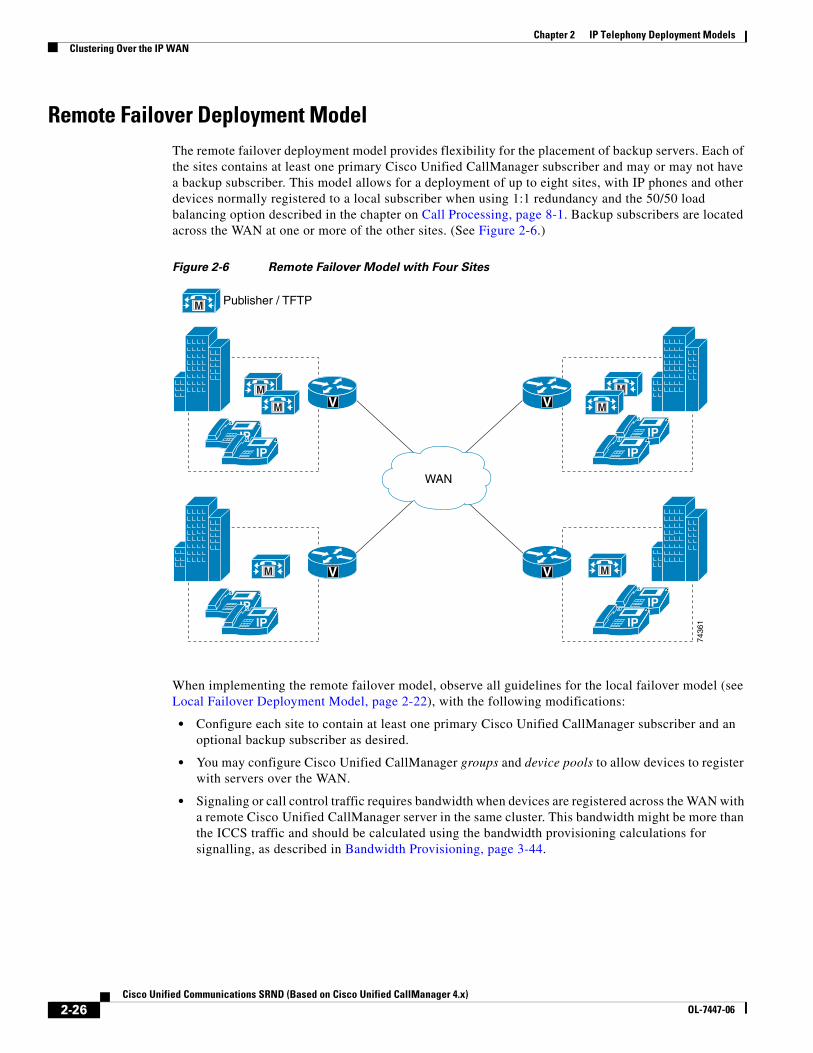
Remote Failover Deployment ModelThe remote failover deployment model provides flexibility for the placement of backup servers. Each of the sites contains at least one primary Cisco Unified CallManager subscriber and may or may not have a backup subscriber. This model allows for a deployment of up to eight sites, with IP phones and other devices normally registered to a local subscriber when using 1:1 redundancy and the 50/50 load balancing option described in the chapter on Call Processing, page 8-1. Backup subscribers are located across the WAN at one or more of the other sites. (See Figure 2-6.)
Figure 2-6 Remote Failover Model with Four Sites
When implementing the remote failover model, observe all guidelines for the local failover model (see Local Failover Deployment Model, page 2-22), with the following modifications:
• Configure each site to contain at least one primary Cisco Unified CallManager subscriber and an optional backup subscriber as desired.
• You may configure Cisco Unified CallManager groups and device pools to allow devices to register with servers over the WAN.
• Signaling or call control traffic requires bandwidth when devices are registered across the WAN with a remote Cisco Unified CallManager server in the same cluster. This bandwidth might be more than the ICCS traffic and should be calculated using the bandwidth provisioning calculations for signalling, as described in Bandwidth Provisioning, page 3-44.
M
IPIP
M
M
M V
IPIP
IP
M V V
7436
1IP
M
IP
MV
IP
WAN
Publisher / TFTP
2-26Cisco Unified Communications SRND (Based on Cisco Unified CallManager 4.x)
OL-7447-06
Chapter 2 IP Telephony Deployment ModelsDesign Considerations for Section 508 Conformance
Design Considerations for Section 508 ConformanceRegardless of which deployment model you choose, you should consider designing your IP telephony network to make the telephony features more accessible to users with disabilities, in conformance with Section 255 of the Telecommunications Act and U.S. Section 508.
Observe the following basic design guidelines when configuring your IP telephony network to conform to Section 508:
• Enable Quality of Service (QoS) on the network.
• Configure only the G.711 codec for phones that will be connected to a terminal teletype (TTY) device or a Telephone Device for the Deaf (TDD). Although low bit-rate codecs such as G.729 are acceptable for audio transmissions, they do not work well for TTY/TDD devices if they have an error rate higher than 1% Total Character Error Rate (TCER).
• Configure TTY/TDD devices for G.711 across the WAN, if necessary.
• Enable (turn ON) Echo Cancellation for optimal performance.
• Voice Activity Detection (VAD) does not appear to have an effect on the quality of the TTY/TDD connection, so it may be disabled or enabled.
• Configure the appropriate regions and device pools in Cisco Unified CallManager to ensure that the TTY/TDD devices always use G.711 codes.
• Connect the TTY/TDD to the IP telephony network in either of the following ways:
– Direct connection (Recommended method)
Plug a TTY/TDD with an RJ-11 analog line option directly into a Cisco FXS port. Any FXS port will work, such as the one on the Cisco VG248, Catalyst 6000, Cisco ATA 188 module, or any other Cisco voice gateway with an FXS port. Cisco recommends this method of connection.
– Acoustic coupling
Place the IP phone handset into a coupling device on the TTY/TDD. Acoustic coupling is less reliable than an RJ-11 connection because the coupling device is generally more susceptible to transmission errors caused by ambient room noise and other factors.
• If stutter dial tone is required, use an analog phone in conjunction with an FXS port on the Cisco VG248 or ATA 188.
2-27Cisco Unified Communications SRND (Based on Cisco Unified CallManager 4.x)
OL-7447-06

Chapter 2 IP Telephony Deployment ModelsDesign Considerations for Section 508 Conformance
2-28Cisco Unified Communications SRND (Based on Cisco Unified CallManager 4.x)
OL-7447-06