IP Routing Fast Convergence - · PDF file5 1. Failure Detection 2. Failure Propagation...
91
IP Routing Fast Convergence Miloslav Kopka
Transcript of IP Routing Fast Convergence - · PDF file5 1. Failure Detection 2. Failure Propagation...

IP Routing Fast Convergence
Miloslav Kopka

2
Agenda
Introduction
FIB
Routing Fast Convergence
LFA
BGP PIC

3
Introduction

4
Loss of Connectivity – LoC
Link and/or Node Failures cause packet loss until routing has converged
Loss can be caused by black-holes and/or micro-loops, until all relevant nodes in the path have converged
Time between failure and restoration is called LoC
How much LoC is acceptable?
Minutes?
Seconds?
Milliseconds?
How often is LoC acceptable?

5
1. Failure Detection
2. Failure Propagation (flooding, etc.)
3. Topology/Routing Recalculation
4. Update of the routing and forwarding table (RIB & FIB)
5. Router Platform/Infrastructure – Fast CPU + Dedicated Control Plane
t0 t1 t3 t2 t4
1. 2. 3. 4.
5.
Routing Convergence Components

6
Routing Convergence Components
A B C
D
Folks: my link to
B is down Folks: my link
to C is down
Ok, fine, will use
path via D
I don’t care, nothing
changes for me
Ooops.. Problem
t0 t1 t3 t2 t4 LoC = t4 – t0
7
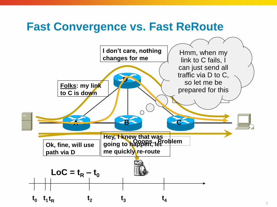
Fast Convergence vs. Fast ReRoute
A B C
D
Folks: my link to
B is down
Folks: my link
to C is down
Ok, fine, will use
path via D
I don’t care, nothing
changes for me
Ooops.. Problem
t0 t1 t3 t2 t4
LoC = tR – t0
Hmm, when my link to C fails, I
can just send all traffic via D to C,
so let me be prepared for this
tR
Hey, I knew that was
going to happen, let
me quickly re-route

8
Fast ReRoute Benefits
Backup path is pre-computed
Reaction to failure is local, immediate propagation and processing on other nodes is not required
LoC as low as a few milliseconds can be achieved (provided the failure is detected quickly)
Prefix independency is key
Cool, so why is not everyone using it?
It is either topology dependant or can be complex to implement (i.e. MPLS TE FRR), but we’re working on this…
It only addresses core/transit node/link failures (edge node failures still require routing convergence)
It is not implemented on all platforms

9
Failure detection
Detecting the failure is one of the most critical and often one of the most challenging part of network convergence
Failure Detection can occur on different levels/layers
Physical Layer (0 & 1) - G.709 (IPoDWDM), SONET/SDH (POS), Ethernet autonegotiation
Transport Layer (2) - PPP or HDLC keepalives, Frame-Relay LMI, ATM-OAM, Ethernet-OAM
Network Layer (3) – IGP Hello, BFD
Application (not covered here)

10
Failure Detection at Layer 3
In some environments, some or all failures require checks at Layer 3 (i.e. IP)
L2 bridged
network
DWDM/X without LoS
propagation
Tunnels (GRE,
IPsec, etc.)

11
Layer 3 – Network/Routing Layer
All IGPs (EIGRP, OSPF and ISIS) use HELLOs to maintain adjacencies and to check neighbour reachability
Hello/Hold timers can be tuned down (“Fast Hellos”), however it is not recommend doing so because
This does not scale well to larger number of neighbors
Not a robust solution, high CPU load can cause false-positives
Having said this: Works reasonably well in small & controlled environments, for example Campus networks
We need another solution: Use BFD!

12
RIB & FIB Update
Most “expensive” convergence component
Linear dependency on the # of changed prefixes
RIB/FIB update is measured on a per entry change and depends on
RP CPU speed
IP vs MPLS (MPLS requires more update time per entry)
Distribution delay: RIB FIB LC-FIB HW-FIB

13
T1
Ti
1 2000
Before
T1
Ti
1 2000 After
Voip gateways
Loopbacks
Tmax(voip)
Tmax(voip) p2p links
RIB/FIB – How much control?
Prefix ordering is an important feature to reduce convergence time
Prefix Prioritization / Local RIB/ Prefix Suppression
Design rule: Keep your IGP slim

14
Prefixes, path lists and paths
Gi1
Gi2
Advertised with next
hop
10.0.0.1/32
Group of prefixes 110.0.0.0/24 110.1.0.0/24 110.2.0.0/24 . . .
Path List
Path 1
Via 10.0.0.1
Path 1
GigE1
Path List
BGP Entry
110.0.0.0/24
BGP Entry
110.1.0.0/24
BGP Entry
110.2.0.0/24
IGP Entry
10.0.0.1/32
PE1 (10.0.0.1)
PE3

15
Non Optimal: Flat FIB
Each BGP FIB entry has its own local Outgoing Interface (OIF) information (ex: GigE1)
Forwarding Plane must directly recurse on local OIF Information
Original Cisco implementation and still in use both by us and competition
FIB changes can take long, dependent on number of prefixes affected
…
BGP Net 110.0.0.0/24
BGP Net 110.1.0.0/24
BGP Net 110.5.0.0/24
IGP Net 10.0.0.1/32
OIF
OIF
OIF
OIF

16
Right Architecture: Hierarchical FIB
Pointer Indirection between BGP and IGP entries allow for immediate update of the multipath BGP pathlist at IGP convergence
Only the parts of FIB actually affected by a change needs to be touched
Used in newer IOS and IOS-XR (all platforms), enables Prefix Independent Convergence
…
BGP nexthop(s)
IGP nexthop(s) Output Interface
BGP Net 110.0.0.0/24
BGP Net 110.1.0.0/24
BGP Net 110.5.0.0/24
BGP
pathlist
PE1
PE2 IGP pathlist
PE2 via P2
Gig1,
dmac=x
IGP pathlist
PE1 via P1
PE1 via P2
Gig2,
dmac=y
PE1
PE2 PE3
P2
P1

17
IP Fast ReRoute – LFA-FRR

18
LFA Fast Reroute Overview
LFA – Loop Free Alternate
“The goal of IP Fast-Reroute is to reduce failure reaction time to 10s of milliseconds by using a pre-computed alternate next-hop, in the event that the currently selected primary next-hop fails, so that the alternate can be rapidly used when the failure is detected.”
-draft-ietf-rtgwg-ipfrr-spec-base-12
IP Fast Reroute is an IP based mechanism that reduces traffic disruption to 10s of milliseconds in event of link or node failure
A failure is locally repaired by router next to failure before routers in network re-converge around such failure
Differs from MPLS Traffic Engineering in many aspects . . .

19
LFA Fast Reroute Buildings Blocks
In order to achieve Fast Reroute, we need the forwarding engine (CEF/FIB) to hold a primary and a backup path for each prefix. The backup path is pre-computed using LFA mechanism so that we can very rapidly switch to it when a failure is detected without further computation.
For MPLS we also need to hold in MPLS forwarding engine (MFI) primary path and backup path labels
Backup paths are computed AFTER the primary path and so do not delay normal convergence
In order to be prefix independent and to minimize backup switchover time, the forwarding engine (FIB) requires to be hierarchical.
A fast detection mechanism is required to trigger the forwarding engine to switch from the primary path to the backup path. (BFD, IPoDWDM, LFS, proactive protection, …)

20
Terminology
D: we will compute the LFA for this destination IGP prefix
S: the router computing the LFA to D
F: a neighbor of S, we typically look at the LFA’s for the prefixes normally routed over link SF
Nx: a neighbor of S
Default link cost: 10
Default link bandwidth: 10
21
Terminology
Path: Outgoing interface and nhop
Primary Path: One of (possibly many) least-cost paths
Secondary: A costlier path than the best.
Backup: an outgoing interface/nhop which is used to replace
another one that went down. It can be:
another primary ECMP nhop
a secondary LFA routing path
a TE-tunnel could be a backup

22
Terminology
LFA: Loop-Free Alternate
N is an LFA for S’s primary path to D via F if ND < NS + SD
Node-protecting LFA if: ND < NF + FD
S F
C
E
D1
D2

23
Per-Prefix LFA FRR
IGP pre-computes a backup path per IGP prefix
IGP Route 1.1.1.1/32
Primary Path: PoS1
Backup Path: <LFA>
FIB pre-installs the backup path in dataplane
Upon local failure, all the backup paths of the impacted prefixes are enabled in a prefix-independent manner (<50msec LoC)

24
Per-Prefix LFA Algorithm
For IGP route D1, S’s primary path is link SF.
S checks for each neighbor N (<>F) whether ND1 < NS + SD1 (Eq1)
“does the path from the neighbor to D1 avoid me?”
If so, it is a loop-free alternate (LFA) to my primary path to D1
S F
C
E
D1
D2

25
Guaranteed-Node-Protecting
Definition: ND < NF + FD (Eq2)
“does the path from the neighbor to D avoid node F?”
S’s primary path to D: E0
S’s LFA candidates: E1 and E2
E1: not guaranteed node protecting
N1 does not meet Eq2
E2: guaranteed node protecting
N2 meets Eq2
S F D E0
E2
N1
N2
20
E1

26
De Facto Node Protection
Choosing a guaranteed node-protecting LFA is not the only way to benefit from LFA node protection
A non-guaranteed node protecting LFA candidate might turn to be node protecting. We call this “De Facto Node Protection”
N2 is not guaranteed node protecting for D: 20 !< 10+10
But if F fails, N2 will trigger its own LFA for the path N2FD (via N2D) and hence the traffic SD avoids F!
S F D E0
E2
N2
20 20

27
A guaranteed-Node-protecting is not always better
Failure Statistics indicate that node failures are very rare
Simulation indicates that non-guaranteed node-protecting LFA’s actually provide De Facto Node Protection in many cases
Priviledging a guaranteed node-protecting LFA might lead to using a non-optimal path
SN2D involves a low-BW link (SN2). It would be used if F would really go down. When F is up and just the link SF goes down, it is much more efficient to use N1.
S F D E0
E2
N1
N2
100, low BW
E1

28
Per-Link LFA Algorithm
A subcase of per-prefix LFA
IGP computation changes (slightly)
one single per-prefix LFA is computed: for address “F”
“a valid backup path to F itself is valid for any destination reached via F”
RIB/FIB representation does not change
one backup path per primary path
all the backup paths are the same
D1: primary path SF, backup path: SC
D2: primary path SF, backup path: SC

29
Example – Control Plane Output
A
C
B
D
E F
100
40
20
20
IGP Per-Link LFA Result:
Link AB is protected via E
IGP Per-Prefix LFA Result:
D’s LFA is via C
B’s LFA is via E
E’s LFA is via E
F’s LFA is via E

30
Per-Prefix vs Per-Link
Better Coverage
Each prefix is analyzed independently. Most often it is the prefix at the other end which has no LFA…
Better Capacity Planning
Each flow is backed up on its own optimized shortest path to the destination
Better Node Protection
Can be verified algorithmically
Same Dataplane Scale
Higher Control Plane CPU consumption

31
One backup path per primary path
IGP will select one and only one backup path per primary path
Need to select an LFA among multiple candidates (tie-break)
Tie-break works as BGP Best-Path
a set of consecutive rules
each rule discards candidates
scheme stops when one single path remains
if a rule excludes all paths, then the rule is skipped
Tie-breaking rules cannot eliminate all candidates
The default Tie breaking order is configurable

32
LDP support
The backup path for destination D must contain the label bound by the backup neighbor
backup label is dependent on (IGP destination, backup path)
This is why, whether the IGP computes per-prefix or per-link, the RIB and FIB representation is always per-prefix
this allows to store the per-path dependent backup label

33
No degradation for IGP FC
Per-Prefix LFA Computation is throttled by its own independent exp-backoff
An LFA computation does not start until the primary computation is finished.
An ongoing LFA computation is interrupted if a new primary computation is scheduled.

34
Restrictions
A link is either configured for per-link LFA OR per-prefix LFA
A given interface should be configured for LFA FRR or TE FRR
Per-prefix LFA should be configured on only point-to-point interfaces.
If Ethernet is used, it should be running in p2p mode. However LAN interfaces could be used as backup.

35
Operation
Show command to provide the % of coverage
across all IGP routes
per IGP priority (critical, high, medium, low)
per primary interface
Show command to display the selected backup path per primary IGP path

36
Benefits
Simple
the router computes everything automatically
<50msec
pre-computed, pre-installed, enabled on link down in a prefix independent manner
prefix-independent for any prefix type
Leverage Hierarchical dataplane FIB
Deployment friendly
no IETF protocol change, no interop testing, incremental deployment

37
Benefits
Good Scaling
No degradation on IGP convergence for primary paths
Node Protection or De Facto
an LFA can be chosen on the basis of the guaranteed-node protection
simulation indicate that most link-based LFA’s anyway avoid the node (ie. De Facto Node Protection)

38
Constraints
Topology dependent
availability of a backup path depends on topology
Is there a neighbor which meets Eq1?

39
LFA Coverage is really excellent
11 real Core Topologies
average coverage: 94% of destinations
5 topologies higher than 98% coverage
Real Aggregation
simple design rules help ensure 100% link/node protection coverage for most frequent real aggregation topologies
RFC6571
Sweet Spot
A simple solution is essential for access/aggregation as it represents 90% of the network size hence complexity

40
High interest for access/aggregation
• Is there a way to also support the ring and “biased square”?
Biased Square
(a<c) Ring

41
Fast ReRoute – Remote LFA
42
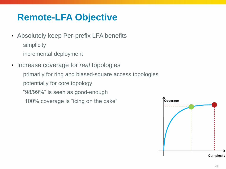
Remote-LFA Objective
• Absolutely keep Per-prefix LFA benefits
simplicity
incremental deployment
• Increase coverage for real topologies
primarily for ring and biased-square access topologies
potentially for core topology
“98/99%” is seen as good-enough
100% coverage is “icing on the cake”

43
The Ring
• No LFA protection in the ring
if E4 sends a C1-destined packet to E3, E3 sends it back to E4

44
Remote LFA (aka PQ Algorithm)
• Any node which meets the P and Q properties
P: the set of nodes reachable from E3 without traversing E4E5
Q: the set of nodes which can reach E5 without traversing E4E5
• Best PQ node
the closest from E4: E1
• Establish a directed LDP session with the selected PQ node
*

45
Remote LFA Protection
• E4’s LIB
E5’s label for FEC C2 = 20
E3’s label for FEC E1 = 99
E1’s label for FEC C2 = 21
• E4’s FIB for destination C2
Primary: out-label = 20, oif = E5
Backup: out-label = 21
oif = [push 99, oif = E3]
RLFA is LFA from a remote node (E1)
*

46
Per-Link Computation
• E4 computes a single PQ node for the link E4E5
P space: does not require any new computation
Nodes whose shortest-path avoid E4E5
Nodes whose shortest-path is E4E5 but have an LFA
Q space: one dijkstra per link (1-2ms Typical)
Dijkstra rooted at E5 with the reverse metrics and with E5E4 branch pruned
• Per-Prefix LFA as if E1 was directly connected neighbor
• Extremely low CPU requirement

47
Per-Prefix Backup
• Exactly like per-prefix LFA but as if the PQ node was directly connected
• Hence, all per-prefix LFA benefits are preserved
each packet uses its shortest-path from the PQ node
Excellent capacity planning
“De Facto” Node protection
(100% node protection for ring and biased square)

48
Remote LFA applied to Biased Square
• Upon E1C1 failure, E1 has no per-prefix LFA to C1
E2 routes C1 via E1
• With Remote LFA, upon E1C1 failure, E1 forwards the packets destined to C1 towards the PQ node (C2) from where the packet reaches C1
E1
Backbone
Access Region
E1 E2
C1 C2 20
10
10
10
*

49
Targeted LDP session
• Upon computation of a new PQ node X, the local router R establishes a targeted LDP session with PQ node X
• X must be configured to accept Targeted LDP session
mpls ldp discovery targeted-hello accept [ from <peer-acl> ]
• Same security model as PWE, VPLS and LDP over Full-Mesh TE deployments

50
Targeted LDP – Scalable
• Odd ring: 2 LDP additional sessions per node
• Even ring: 1 LDP additional session per node
• Biased Square: 1 LDP additional session per node

51
Very simple rules – RFC6571
• In a square, any metric should be less than the sum of the 3 other links
• If C1–C2 Metric is 30 Remote LFA does not work

52
Not yet 100%-guaranteed…
• E1 has no LFA for C1
E2 routes back
• E1 has no Remote LFA for C1
P and Q intersection is null

53
100% - Icing on the cake
• When the P and Q space do not intersect, then setup an RSVP-LSP to the closest Q node
RSVP allows an explicit path and hence a path that avoids the primary link
• Very few RSVP-LSP’s
• Automatically – Detect the Case
Build Explicit Path
Signal RSVP
• 100% guarantee
• Node protection

54
Remote LFA Benefits
• Seamless integration with Per-Prefix LFA
Packets take their shortest paths from the PQ node
Destinations use per-prefix LFA onto physical oif when available (i.e. per-prefix LFA), and per-prefix LFA onto LDP LSP (i.e. Remote LFA) otherwise
• Simple
Automated computation, negligible CPU, low T-LDP requirement
• Incremental Deployment
New code only at the protecting node
• Meet the real coverage requirements
backbone and access/aggregation

55
BGP Fast Convergence

56
BGP “Fast” Convergence
Where/Why do we need BGP Fast Convergence?
Layer 3 VPN Convergence
Peering/Upstream router or link failure
Usually contained within a single AS
IGPs have a few thousand prefixes max, with a couple of hundred important ones
Optimizing the implementation for FC is relatively easy
BGP scales to > million routes
Tuning the protocol and implementation to provide sub-second convergence without sacrificing the scalability is impossible

57
BGP Control-Plane Convergence Components I: Core failure
PE1
3/8, NH 1.1.1.1
NH <PE2>
…
3.0.0.0/8
PE2
1.1.1.1
3/8, NH 1.1.1.5
NH <PE1>
…
1.1.1.5
1. Core Link or node goes down
2. IGP notices failure, computes new paths to
PE1/PE2 3. IGP notifies BGP that a path to a next-hop has
changed 4. PE3 identifies affected paths, runs best path,
path to PE2 no longer as good as the one to
PE1 5. Updates RIB/FIB, traffic
continues
3/8, NH <PE1>
NH <PE2>
…
PE3 NH
<PE2>

58
BGP Control-Plane Convergence Components II: Edge Node Failure
PE1
3/8, NH 1.1.1.1
NH <PE2>
…
3.0.0.0/8
PE2
1.1.1.1
3/8, NH 1.1.1.5
NH <PE1>
…
1.1.1.5
Edge Node (PE1) goes down
2. IGP notices failure, update RIB, remove path to
PE1 3. IGP notifies BGP that path to PE1 is now longer
valid 4. PE3 identifies affected paths, runs best path,
removes paths via PE1
5. Updates RIB/FIB, traffic
continues
3/8, NH <PE1>
NH <PE2>
…
PE3

59
BGP Control-Plane Convergence Components III: Edge Neighbour Failure (with next-hop-self)
PE1
3/8, NH 1.1.1.1
NH <PE2>
…
3.0.0.0/8
PE2
1.1.1.1
3/8, NH 1.1.1.5
NH <PE1>
…
1.1.1.5
1. Edge link on PE1 goes down
2. eBGP session goes down
3. PE1 identifies affected paths, runs best path
4. PE1 sends withdraws to other PEs
5. PE2 & 3 run best path, update
RIB/FIB, traffic continues
3/8, NH <PE1>
NH <PE2>
…
PE3
Withdraw: 3/8, NH
<PE1>

60
BGP Control-Plane Convergence Components
Failure Detection
Reaction to Failure
Failure Propagation
RIB/FIB Update

61
Control vs. Data Plane Convergence
Control Plane Convergence
For the topology after the failure, the optimal path is known and installed in the dataplane
May be extremely long (table size)
Data Plane Convergence
Once IGP convergence has detected the failure, the packets are rerouted onto a valid path to the BGP destination
While valid, this path may not optimal one from a control plane convergence viewpoint
We want this behaviour, in a prefix-independent way – that’s what this session is all about

62
BGP Control-Plane Fast Convergence – Summary
In reasonably small L3VPN environments (< 1000 pfx), sub-second can be achieved for most failures
be aware of active/standby policies, takes much longer
However, with larger number of VRFs and/or routing tables, sub-5 seconds is a more realistic target
Internet routing table convergence takes minutes
We want prefix-independent behaviour BGP Prefix Independent Convergence (BGP-PIC)

63
BGP PIC Core
Core Failure: a failure within the analyzed AS
IGP convergence on PE3 leads to a modification of the RIB path to PE1
BGP Dataplane Convergence is finished assuming the new path to the BGP Next Hop is leveraged immediately (BGP PIC Core)
BGP NHT sends a “modify” notification to BGP which may trigger BGP Control-Plane Convergence. This may be long without impacting Tight-SLA experience
PE1
PE2 PE3
P2
P1

64
Characterization BGP PIC Core
As soon as IGP converges, the IGP pathlist memory is updated, and hence all children BGP PL’s leverage the new path immediately
Optimum convergence, Optimum Load-Balancing, Excellent Robustness
Core
1
10
100
1000
10000
100000
1
2500
0
5000
0
7500
0
1000
00
1250
00
1500
00
1750
00
2000
00
2250
00
2500
00
2750
00
3000
00
3250
00
3500
00
PrefixL
oC
(m
s) PIC
no PIC
…
BGP nexthop(s)
IGP nexthop(s) Output Interface
BGP Net 110.0.0.0/24
BGP Net 110.1.0.0/24
BGP Net 110.5.0.0/24
BGP
pathlist
PE1
PE2 IGP
pathlist
PE2 via P2
Gig1,
dmac=x
IGP
pathlist
PE1 via P1
PE1 via P2
Gig2,
dmac=y
PE1
PE2 PE3
P2
P1

65
BGP PIC Edge
Edge Failure: a failure at the edge of the analyzed AS
IGP convergence on PE3 leads to a deletion of the RIB path to BGP Next-Hop PE1
BGP Dataplane Convergence is kicked in on PE3 (BGP PIC Edge) and immediately redirects the packets via PE2
BGP NHT sends a “delete” notification to BGP which triggers BGP Control-Plane Convergence. This may be long, but without impacting Tight-SLA experience
PE1 does not set next-hop-self
PE1
PE2 PE3
P2
P1
PE1
PE2 PE3
P2
P1

66
Characterization BGP PIC Edge
At IGP Convergence time, the complete IGP pathlist to PE1 is deleted
SW FIB walks the linked list of parent BGP path lists and in-place modify them to use alternate next hops (ECMP or backup). BGP Path lists are shared, so this is efficient
…
BGP nexthop(s)
IGP nexthop(s) Output Interface
BGP Net 110.0.0.0/24
BGP Net 110.1.0.0/24
BGP Net 110.5.0.0/24
BGP
pathlist
PE1
PE2 IGP
pathlist
PE2 via P2
Gig1,
dmac=x
IGP
pathlist
PE1 via P1
PE1 via P2
Gig2,
dmac=y
PE1
PE2 PE3
P2
P1
1
10
100
1000
10000
100000
1000000
0
50000
100000
150000
200000
250000
300000
350000
400000
450000
500000
Prefix
msec
250k PIC
250k no PIC
500k PIC
500k no PIC

67
PE1
PE2 PE3
P2
P1
BGP PIC Edge and Next-Hop Self
With the edge device setting next-hop to its loopback (next-hop-self), edge link going down does not change next-hop as seen on other routers
Failure goes unnoticed by others!
However: Next-hop on edge device with failing link goes away, so this device can react in PIC-Edge fashion
Traffic re-routed via core to alternate edge
PE1 does set next-hop-
self

68
Summary: BGP PIC Edge application points
Z
/
z
AS X AS
Y
iBGP
eBGP
PE
3
P
E
2
P
E
1
Z
/
z
AS X AS
Y
iBGP
eBGP
P
E
3
P
E
2
P
E
1
PE1 does not set next-
hop-self
Z
/
z
AS X AS
Y
iBGP
eBGP
P
E
3
P
E
2
P
E
1
PE1 sets next-hop-self
PE3 must be the reacting
point as PE1 is down.
PE3’s reaction is triggered
by IGP convergence
PE3 and PE1 may be the
reacting point.
PE3 reaction is triggered by
IGP convergence
PE1 reaction is triggered by
local interface failure
PE1 is the reacting point.
PE1 reaction is triggered by
local interface failure
Note: PE3 is blind in this
case as the next-hop is
PE1

69
Key Take-Aways
PIC Core and PIC-Edge leverage hierarchical forwarding structure
PIC Core: Path towards Next-Hop changes – IGP LoadInfo changed
PIC Edge: Next-Hop goes away – BGP Path list changed
All BGP prefixes (no matter how many!!) converge as quickly as their next-hop
Generally, IGP is responsible for next-hop convergence BGP convergence depends on IGP convergence
So? What do I need to do to speed up my BGP convergence with BGP PIC???

70
Designing for BGP PIC

71
Designing (for) BGP PIC
BGP PIC is a forwarding / data plane layer feature, so what’s there to design???
Well, there is a bit:
BGP data plane convergence depends on how quickly the next-hop(s) converges (or is deleted), which boils down to
Fast failure detection
Fast IGP convergence
For PIC Edge, we need some form of tunnelling/encapsulation between edge devices
For BGP PIC-Edge, we need to have an alternative/backup next-hop
…
BGP nexthop(s)
IGP nexthop(s) Output Interface
BGP Net
110.0.0.0/24
BGP Net
110.1.0.0/24
BGP Net
110.5.0.0/24
BGP
pathlist
PE1
PE2
IGP pathlist
PE2 via P2
Ge1,
dmac=x
IGP
pathlist
PE1 via X4
PE1 via P2
Ge2,
dmac=y
…
BGP nexthop(s)
IGP nexthop(s) Output Interface
BGP Net
110.0.0.0/24
BGP Net
110.1.0.0/24
BGP Net
110.5.0.0/24
PE1
PE2
IGP pathlist
PE2 via P2
Ge1,
dmac=x
IGP
pathlist
PE1 via X4
PE1 via P2
Ge2,
dmac=y

72
BGP PIC Design I: Fast IGP Convergence
Details of IGP Convergence tuning is outside the scope of this session, but in principle
1. Provide for fast failure detection (BFD, carrier-delay) Avoid tuning down BGP hello/hold timers for failure detection
2. For IOS, tune OSPF/ISIS LSA- and SPF-throttle timers
Reduces convergence from ~5 down to <1 sec
NX-OS and IOS-XR already tuned reasonably fast
3. Prioritize next-hop prefixes (i.e. PE loopback addresses) to make sure they converge before less important prefixes (i.e. link addresses or the like)
4. Keep the IGP slim and clean, use point-to-point adjacencies, carry customer routes in BGP
5. Evaluate Fast ReRoute techniques (like LFA-FRR) to further improve convergence

73
BGP PIC Design II: PE – PE Encapsulation
Some BGP-PIC Edge convergence scenarios lead to edge device forwarding packets on to alternate edge, back via the core
Core routers might be unaware of the failure (yet) and send packets back to the previous edge device, causing a loop
Solution: Ensure there is no intermediate IP destination lookup, via means of encapsulation:
Direct adjacency between edges (physical link or GRE tunnel)
Using MPLS LSPs/Tunnels in the core
Loop
!

74
BGP PIC Design III: More than one path
When a PE/next-hop goes away, the re-routing node needs already a backup/alternate path in its FIB
This sounds rather obvious, but can be non-trivial in some scenarios
Scenario 1: Route Reflectors
Scenario 2: Active/Standby Routing Policies let’s start with this one first...
PE1
PE2
PE3
RR
PE4
1/8
1/8 via PE2
1/8 via PE1

75
Scenario 2: BGP Active/Standby – The Problem (1/3)
Initial State: CE just comes up
PE1 (active)
PE2 (standby)
Update:
NetA, via PE1, LP: 200
Update:
NetA, via PE2 LP:
100 i NetA, via PE1 LP: 200
via PE2 LP: 100
NetA, via s0 LP: 100
NetA, via e0 LP:
200
CE e0
s0

76
BGP Active/Standby – The Problem (2/3)
Initial State: CE just comes up
PE1 (active)
PE2 (standby) i NetA, via PE1 LP: 200
via PE2 LP: 100
NetA, via s0 LP: 100
via PE1 LP: 200
NetA, via e0 LP: 200
via PE2 LP:
100
CE e0
s0
Update:
NetA, via PE1, LP: 200
Update:
NetA, via PE2 LP:
100

77
BGP Active/Standby – The Problem (3/3)
PE2 withdraws its eBGP path as it is no longer best
But now all other PEs are left with a single path – no alternate path for PIC-Edge to converge to!!!
PE1 (active)
PE2 (standby) i NetA, via PE1 LP: 200
NetA, via s0 LP: 100
via PE1 LP: 200
NetA, via e0 LP: 200
CE e0
s0
Withdrawal:
NetA, via PE2 LP:
100

78
BGP Active/Standby – The Solution: BGP Best-External
PE2 keeps advertising his best external path
Availability: 12.2SRE/15.0S/MR, XE3.1 and XR3.9
PE1 (active)
PE2 (standby) i NetA, via PE1 LP: 200
via PE2 LP: 100
NetA, via s0 LP: 100
via PE1 LP: 200
NetA, via e0 LP: 200
via PE2 LP: 100
CE e0
s0
Update:
NetA, via PE1, LP: 200
Update:
NetA, via PE2 LP:
100
• PE2 keeps advertising his best external path
• Requires no BGP protocol change (local change only)
• Availability: 12.2SRE/15.0S/MR, XE3.1 and XR3.9
PE3

79
PE1
PE2
PE3
RR
PE4
1/8
Scenario1: iBGP Path Propagation and Reflection
Regular BGP BestPath algorithm leads to an RR only reflecting one path, namely its best path
Without explicit policy either hot-potato policy prevails (rule 8) or the lowest neighbor address (rule 13) is used as tiebreaker
What can we do to propagate both paths to PE3/4?
1/8 via PE2
1/8 via PE1

80
PE1
PE2
PE3
PE4
1/8
RR
Path Diversity in L3VPN Environments
Important sites are dual homed
Unique RD allocation ensures both paths are learned, even through route reflectors
For active/backup scenarios, “best-external” is required
RD1
RD2
RD2:1/8 via PE2,
Label L2
RD1:1/8 via
PE2,
Label L1

81
Solution 1: Internet in a VRF
Unique RD allocation ensures both paths are learned, even through
route reflectors
Consider per-vrf or per-CE label allocation when advertising full
Internet routing table within a VRF
PE1
PE2
PE3
PE4
1/8
RR RD1
RD2
RD2:1/8 via PE2,
Label L2
RD1:1/8 via
PE2,
Label L1

82
PE1
PE2
PE3
PE4
1/8
Solution 2: No RR
Full iBGP mesh
Yes, I am serious , at least for reasonably sized and static environments

83
PE1
PE2
PE3
RR
PE4
1/8
Solution 3: RR + partial iBGP mesh
Done in practice by several operators
Very specific and hence difficult to abstract any rule. Just know it exists and analyses the possibility.
1/8 via
PE2
1/8 via PE1

84
PE1
PE2
PE3
RR
PE4
1/8
Solution 4: Engineered RR
Some operators place their RR’s in the topology to ensure they select different paths. Their PE’s are clients to multiple RR’s.
the top RR is closer to PE1 and selects the black path
the bottom RR is closer to PE2 and selects the blue path
Above behaviour can also be achieved using specific BGP policies
RR

85
Solution 5: AddPath New Capability to allow a BGP speaker to advertise more than one path
(“The holy grail”)
Available in IOS-XR 4.0, IOS-XE 3.7, 15.2(4)S, 15.3T
Requires support for this functionality on RR and PEs
PE1
PE2
RR
PE4
1/8
1/8 via PE2
1/8 via PE1
PE3
http://www.cisco.com/en/US/docs/ios-xml/ios/iproute_bgp/configuration/xe-3s/asr1000/irg-additional-
paths.html

86
Solution 6: BGP Diverse Paths (aka “Shadow RR”)
New feature (IOS-XE 3.4S) allows a RR to advertise a 2nd best path
Two deployment models:
1. RR maintains two iBGP session to PEs (shown below) “Primary” connection advertises best path (PE1) “Secondary” connection (or secondary RR) advertises next-best-path (PE2)
2. Dual RRs, first RR advertises best, the other RR the blue/2nd best path
No update on PEs/RR-clients required PE1
PE2
RR
PE4
1/8
1/8 via PE2
1/8 via PE1
http://www.cisco.com/en/US/docs/ios/ios_xe/iproute_bgp/configuration/guide/irg_diverse_pat
h_xe.html
PE3

87
L3VPN: RR Redundancy (IOS) The Problem
PE1
rd1:10/8
10.0.0.0/8
PE2
1. RR1 goes down
Traffic not affected as RR1 is not in
forwarding path
2. After iBGP hold-time expires, PE3
purges routes from RR1
VRF left without routes to 10/8
3. Alternative paths not imported
until next import-scanner run
(up to 15 seconds)
not in 15M/S or SRE
PE3
rd2:10/8
rd1:10/8, NH PE1
rd2:10/8, NH PE2
rd1:10/8, NH PE1
rd2:10/8, NH PE2
> rd1:10/8, NH PE1, from RR1
rd1:10/8, NH PE1, from RR2
> rd2:10/8, NH PE2, from RR1
rd2:10/8, NH PE2, from RR2
vrf import
> rd3:10/8, NH PE1, from RR1
> rd3:10/8, NH PE2, from RR1
RR1
RR2
RR2
RR2
By default, BGP only imports a single best-path from each rd:prefix
Assumptions: Use of unique RDs per PE

88
L3VPN: RR Redundancy (IOS) The Solution
Import more than the best path
or in 12.2SRE/15.0M
Be aware of addtl. memory consumption (~100 bytes/path)
router bgp ..
address-family ipv4 vrf …
maximum-paths [ibgp 2] import 4
> rd1:10/8, NH PE1, from RR1
rd1:10/8, NH PE1, from RR2
> rd2:10/8, NH PE2, from RR1
rd2:10/8, NH PE2, from RR2
vrf import
> rd3:10/8, NH PE1, from RR1
rd3:10/8, NH PE1, from RR2
> rd3:10/8, NH PE2, from RR1
rd3:10/8, NH PE2, from RR2
PE3
router bgp ..
address-family ipv4 vrf …
import path selection all
import path limit 4

89
RR Failure
RR Failure causes no immediate LoC as Forwarding Plane not affected
BGP Hello’s detect RR failure
PE will switch to paths received from redundant RR
Make sure all paths are imported
Goal: Minimize non-redundant state as much as possible

90
Designing (for) BGP PIC – Summary
Work on the baseline – Improve your IGP convergence
Use BFD for speedy eBGP failure detection
Consider enabling MPLS to provide PE-PE tunnelling
Ensure you have multiple paths – and keep this always in the back of your mind, whatever BGP designs/services you are coming up with This one is the hardest one to fix once solutions/etc. are deployed