Ionizer - SMC株式会社 Vacuum pads are excluded from this 1 year warranty. A vacuum pad is a...
80
1 Document No.IZ※-OMT0049 PRODUCT NAME Ionizer MODEL / Series IZT40,41,42series
Transcript of Ionizer - SMC株式会社 Vacuum pads are excluded from this 1 year warranty. A vacuum pad is a...

1
Document No.IZ※-OMT0049
PRODUCT NAME
Ionizer
MODEL / Series
IZT40,41,42series
2
Contents
Safety Instructions ...................................................................................................................................................................... 3
1. How to Order .......................................................................................................................................................................... 11
1-1. System construction ...................................................................................................................................................... 11
1-2. How to Order ................................................................................................................................................................... 14
1-2-1. Product number for single unit (to order separately) ................................................................................................. 15
1-2-2. Made to Order ........................................................................................................................................................... 16
1-2-3. Accessories (ordered separately) .............................................................................................................................. 17
1-2-4. Sold separately ......................................................................................................................................................... 18
2. Procedures to Operation ....................................................................................................................................................... 20
2-1. Flow chart to operation .................................................................................................................................................. 20
2-2. Initial setting (Initial setting is not necessary for IZT40) ............................................................................................. 20
3. Installation and wiring ......................................................................................................................................................... 21
3-1. Installation of Ionizer ...................................................................................................................................................... 21
3-1-1. Precautions for Installation ........................................................................................................................................ 21
3-1-2. Adjustment of Pressure (Flow adjustment) ................................................................................................................ 21
3-1-3. Selection of piping port size ...................................................................................................................................... 21
3-1-4. Distance for installation ............................................................................................................................................. 22
3-1-5. Installation of bracket for bar ..................................................................................................................................... 22
3-1-6. Connecting the controller and high voltage power supply module ............................................................................ 23
3-1-7. Installing the controller and high voltage power supply module ................................................................................ 25
3-1-8. Routing of cables ...................................................................................................................................................... 30
3-2. Wiring .............................................................................................................................................................................. 33
3-2-1. Ground the ground terminal ...................................................................................................................................... 33
3-2-2. Connection Circuit ..................................................................................................................................................... 33
3-2-3. Wiring of the AC adapter ........................................................................................................................................... 35
3-3. Timing chart .................................................................................................................................................................... 36
3-3-1. IZT40 ......................................................................................................................................................................... 36
3-3-2. IZT41、IZT42 ............................................................................................................................................................. 39
4. Function ................................................................................................................................................................................ 43
4-1. Name of Parts ................................................................................................................................................................. 43
4-1-1. Controller .................................................................................................................................................................. 43
4-1-2. High voltage power supply module ........................................................................................................................... 45
4-2. Operation modes ............................................................................................................................................................ 46
4-2-1. Operation modes of IZT40 and IZT41 ....................................................................................................................... 46
4-2-2. Operation modes of IZT42 ........................................................................................................................................ 46
4-3. High voltage power supply module CH number setting ............................................................................................. 47
4-4. Controller setting............................................................................................................................................................ 48
4-4-1. Operation overview ................................................................................................................................................... 48
4-4-2. Channel selection mode ............................................................................................................................................ 50
4-4-3. Frequency set mode ................................................................................................................................................. 51
4-4-4. Offset voltage adjustment mode ................................................................................................................................ 52
4-4-5. Balance control selection mode ................................................................................................................................ 53
4-4-6. Emitter contamination detection level selection mode ............................................................................................... 54
4-4-7. Key-lock setting mode ............................................................................................................................................... 55
4-4-8. Ion generation stop mode ......................................................................................................................................... 56
4-5. Alarm function ................................................................................................................................................................ 57
4-5-1. Alarms for IZT40 ........................................................................................................................................................ 57
4-5-2. Alarms for IZT41 and IZT42 ...................................................................................................................................... 58
4-5-3. Details of the alarms ................................................................................................................................................. 59
5. Performance ........................................................................................................................................................................... 61
5-1. Installation distance and discharge time (discharge time of 1000V→100V) ............................................................. 61
5-2. Potential amplitude ........................................................................................................................................................ 63
5-3. De-ionizing range ........................................................................................................................................................... 64
5-4. Flow - Pressure characteristics .................................................................................................................................... 66
6. Dimensions ............................................................................................................................................................................ 67
7. Specifications ........................................................................................................................................................................ 76
8. Troubleshooting ..................................................................................................................................................................... 77
9. Maintenance ........................................................................................................................................................................... 78

3
Safety Instructions These safety instructions are intended to prevent hazardous situations and/or equipment damage. These instructions indicate the level of potential hazard with the labels of “Caution,” “Warning” or “Danger.” They are all important notes for safety and must be followed in addition to International Standards (ISO/IEC)*1) , and other safety regulations. *1) ISO 4414: Pneumatic fluid power -- General rules relating to systems. ISO 4413: Hydraulic fluid power -- General rules relating to systems. IEC 60204-1: Safety of machinery -- Electrical equipment of machines .(Part 1: General requirements) ISO 10218: Manipulating industrial robots -Safety. etc.
Caution Caution indicates a hazard with a low level of risk which, if not avoided, could result
in minor or moderate injury.
Warning Warning indicates a hazard with a medium level of risk which, if not avoided, could
result in death or serious injury.
Danger Danger indicates a hazard with a high level of risk which, if not avoided, will result in death or serious injury.
Warning 1. The compatibility of the product is the responsibility of the person who designs the equipment or
decides its specifications. Since the product specified here is used under various operating conditions, its compatibility with specific equipment must be decided by the person who designs the equipment or decides its specifications based on necessary analysis and test results. The expected performance and safety assurance of the equipment will be the responsibility of the person who has determined its compatibility with the product. This person should also continuously review all specifications of the product referring to its latest catalog information, with a view to giving due consideration to any possibility of equipment failure when configuring the equipment.
2. Only personnel with appropriate training should operate machinery and equipment. The product specified here may become unsafe if handled incorrectly. The assembly, operation and maintenance of machines or equipment including our products must be performed by an operator who is appropriately trained and experienced.
3. Do not service or attempt to remove product and machinery/equipment until safety is confirmed. 1.The inspection and maintenance of machinery/equipment should only be performed after measures to
prevent falling or runaway of the driven objects have been confirmed. 2.When the product is to be removed, confirm that the safety measures as mentioned above are implemented and the power from any appropriate source is cut, and read and understand the specific product precautions of all relevant products carefully. 3. Before machinery/equipment is restarted, take measures to prevent unexpected operation and malfunction.
4. Contact SMC beforehand and take special consideration of safety measures if the product is to be used in any of the following conditions. 1. Conditions and environments outside of the given specifications, or use outdoors or in a place exposed to direct sunlight. 2. Installation on equipment in conjunction with atomic energy, railways, air navigation, space, shipping,
vehicles, military, medical treatment, combustion and recreation, or equipment in contact with food and beverages, emergency stop circuits, clutch and brake circuits in press applications, safety equipment or other applications unsuitable for the standard specifications described in the product catalog.
3. An application which could have negative effects on people, property, or animals requiring special safety analysis.
4.Use in an interlock circuit, which requires the provision of double interlock for possible failure by using a mechanical protective function, and periodical checks to confirm proper operation.

4
Safety Instructions
Caution 1. The product is provided for use in manufacturing industries.
The product herein described is basically provided for peaceful use in manufacturing industries. If considering using the product in other industries, consult SMC beforehand and exchange specifications or a contract if necessary.
If anything is unclear, contact your nearest sales branch.
Limited warranty and Disclaimer/Compliance Requirements The product used is subject to the following “Limited warranty and Disclaimer” and “Compliance Requirements”. Read and accept them before using the product.
Limited warranty and Disclaimer
1.The warranty period of the product is 1 year in service or 1.5 years after the product is
delivered,whichever is first.2) Also, the product may have specified durability, running distance or replacement parts. Please consult your nearest sales branch.
2. For any failure or damage reported within the warranty period which is clearly our responsibility, a replacement product or necessary parts will be provided. This limited warranty applies only to our product independently, and not to any other damage
incurred due to the failure of the product. 3. Prior to using SMC products, please read and understand the warranty terms and disclaimers
noted in the specified catalog for the particular products.
2) Vacuum pads are excluded from this 1 year warranty. A vacuum pad is a consumable part, so it is warranted for a year after it is delivered.
Also, even within the warranty period, the wear of a product due to the use of the vacuum pad or failure due to the deterioration of rubber material are not covered by the limited
warranty.
Compliance Requirements
1. The use of SMC products with production equipment for the manufacture of weapons of mass destruction(WMD) or any other weapon is strictly prohibited.
2. The exports of SMC products or technology from one country to another are governed by the relevant security laws and regulation of the countries involved in the transaction. Prior to the shipment of a SMC product to another country, assure that all local rules governing that export
are known and followed.
Caution SMC products are not intended for use as instruments for legal metrology.
Measurement instruments that SMC manufactures or sells have not been qualified by type approval tests relevant to the metrology (measurement) laws of each country.
Therefore, SMC products cannot be used for business or certification ordained by the metrology
(measurement) laws of each country.
The product is provided for use in manufacturing industries. The product herein described is basically provided for peaceful use in manufacturing industries. If considering using the product in other industries, consult SMC beforehand and exchange specifications or a contract if necessary. 契約などを行ってください。
The product is provided for use in manufacturing industries. The product herein described is basically provided for peaceful use in manufacturing industries. If considering using the product in other industries, consult SMC beforehand and exchange specifications or a contract if necessary. 契約などを行ってください。
! Caution
SMC products are not intended for use as instruments for legal metrology.
Measurement instruments that SMC manufactures or sells have not been qualified by type approval tests relevant to the metrology (measurement) laws of each country. Therefore, SMC products cannot be used for business or certification ordained by the metrology (measurement) laws of each country.

5
1) This product is intended for use in general factory automation equipment.
· If considering using the product for other applications (especially those indicated in (4) on page 3), please consult SMC beforehand.
2) Use within the specified voltage and temperature range.
· Operation with a voltage other than that specified can cause malfunction, damage to the product, electric shock or fire.
3) Use clean compressed air as fluid. (Air quality Class 2.6.3 specified in ISO 8573-1: 2012 is
recommended.)
· Never use flammable gas or an explosive gas as a fluid and never use this product in the presence of such gases.
· This may lead to fire or explosion. Please contact SMC if using for fluids other than compressed air. 4) This product is not designed to be explosion proof.
· Never use in an atmosphere of potentially explosive dust, flammable gas or explosive gas. Fire or an explosion can result.
1) Clean room specification is not available.
· When using in a clean room environment, confirm the required cleanliness before use.
· Fine particles are generated due to wear of emitters and motor sliding during operation.
1) Reserve an enough space for maintenance, piping and wiring.
· Please take into consideration that the one-touch fittings for supplying air, need enough space for the air tubing to be easily attached/detached.
· To avoid unreasonable stress applied to the connector and one-touch fitting mounting parts, bending of the cable or air tubing should be more than the minimum bending radius.
· If the cable is bent in an acute angle or load is applied to the cable repeatedly, it may cause malfunction, wire damage or fire.
Minimum bending radius: Power supply cable: 40 mm Separate cable (optional): 40mm High voltage cable: 30mm
NOTE: This is an allowable bend radius at 20oC. Bend radius should be larger at lower than 20
oC.
Regarding the minimum bending radius of the air tubing, refer to the operation manual or catalog for tubing.
2) Wiring high voltage cable
· Use specified cable holder (IZT40-E1 or IZT40-E2) for installing high voltage cables.
· Follow the items below when installing high voltage cables. If items below are not followed, insulation performance of high voltage cable decreases, causing the failure of ionizer, leading to electrical shock or fire.
a. Do not cut the cable. b. Keep the minimum bend radius of the cable. c. Do not tighten the cable too much by tying band. Do not deform the cable by placing object on the cable. d. Avoid the factor of cable runaway such as cable duct. e. Do not twist or damage to the cable. If the cable is damaged, it should be replaced.
3) Fix the high voltage cable connector using 2 screws included in accessory.
· Fix the connector using 2 cross recessed round head screws (M4 x10L) referring to Table 1. Reference of tightening torque.
Warning
Caution
Warning
Mounting
Selection

6
4) Mount to the flat surface and do not apply impact load or excessive external force.
· Mounting on an uneven surface will apply excessive force to the housing and bracket, which may lead to damage or failure.
· Do not drop or apply excessive shock. Otherwise, damage or an accident may occur. 5) Install the product so that the bar does not have an excessive deflection.
· For a bar length of 820mm or longer, support the bar at both ends and in the middle by using brackets (IZS40-BM1 or IZT40-BM2). If the bar is held only at the both ends, self-weight of the bar causes deflection, resulting in damage or deformation to the bar.
6) Avoid using in a place where noise (electromagnetic wave and surge) is generated.
· If the product is used in an environment where noise is generated, it may lead to malfunction or deterioration or damage of the internal elements.
· When the presence of noise is suspected, take preventive measures against noise and avoid the crossing wires such as power line and high voltage line.
7) Tighten the screws to the specified torque.
· If the screws are tightened in excess of the specified torque range, it may damage the mounting screws or mounted areas.
· If the tightening torque is insufficient, the mounting screws and brackets may become loose.
8) Do not directly touch the emitters.
· Do not directly touch the emitter with your finger. If the needle sticks to your finger, or electrical shock makes an instantaneous rapid body motion to escape from the shock, causing injury.
· If emitter or cartridge is damaged by tools, etc., it may interfere with the specified function and performance, and may also cause operation failure and accident.
9) Do not affix any tape or labels to the controller, high voltage power supply module or bar.
· If the tape or label contains any conductive adhesive or reflective paint, a dielectric phenomenon may occur due to ions arising from such substances, resulting in electrostatic charging or electric leakage, causing malfunction, breakage, electric shock or fire.
Parts Product No. Connection Screw(Accessory) Tightening torque Note
Controller 2pcs. 0.25 to 0.35Nm
High voltage power
supply module2pcs. 0.25 to 0.35Nm
Spacer for separate cable D-sub connector(plug) 2pcs. 0.40 to 0.60Nm
Intermediate bracket 2 IZT40-BM2
Bracket
(for angle adjustment) M4x16L
2pcs.0.47 to 0.49Nm
Intermediate bracket 1 IZT40-BM1 0.72 to 0.76Nm
Direct connection
Mounting angle adjustment
Cable holder IZT40-E□ Location
M4x8L(Recommended)
2pcs.
0.19 to 0.21Nm Wiring high voltage cable
Install to DIN rail
Bar
(High voltage cable with connector)IZTB4□-□□□□□-□-□
High voltage power
supply module
M4x10L
2pcs.0.49 to 0.53Nm Mounting of high voltage cable
High voltage power
supply module
Separate cableIZT40-CF□ Separate connection
DIN rail mounting bracket IZT40-B□
ControllerM4x6L
2pcs.1.30 to 1.50Nm
DIN rail mounting bracket
1.30 to 1.50Nm
DIN railM4x6L
2pcs.1.30 to 1.50Nm
M4x6L
IZT40-B2:4pcs.
IZT42-B3:8pcs.
ControllerIZTC40
IZTC41
High voltage power
supply module
M4x30L
2pcs.0.22 to 0.24Nm
Table 1. Reference of tightening torque
End bracket IZT40-BE□
Bar end bracketM4x8L
2pcs.0.51 to 0.55Nm Installation of bracket for bar
M4x8L
2pcs.0.72 to 0.76Nm
The emitter carries high voltage. If foreign matter is inserted or human body touches the emitter, electrical shock or instantaneous reaction of body to escape from the shock, causing injury.
High voltage caution

7
10) Be sure to remove power supply and air supply to the controller, high voltage power supply module and bar before starting the product installation.
· If installation or adjustment is performed being supplied with power or air, electric shock, failure or injury can result.
11) High voltage power supply module uses a fan. 20mm or
more space from the exhaust port is necessary for ventilation.
· Or install the product in a ventilated location so peripheral device are not affected.
12) Do not damage the cable or apply a heavy object or pinch
the cable. Avoid repeatedly bending or stretching the cable.
· It may cause an electric shock, fire, or breaking of wire. 13) Do not carry this product by holding its cables.
· It may cause an injury or damage to the product.
1) When IZT4□ series is installed, keep space below from structures or components.
· If there are electrically conductive objects such as walls or structures close to the bar, generated ions may not reach the target object effectively or product failure or electric shock can result due to dielectric or short-circuit.
2) After installation, verify the performance of this product.
· The performance of the product varies depending on the surrounding installation and operating conditions. After installation, verify the performance of this product.
3) When installing Ionizers which operate in DC mode (one polarity, positive or negative) with IZT41 or IZT42 close together, they should be positioned at least two meters away from each other.
· When IZT41 or IZT42 which operates in AC close to the Ionizer which operates in DC mode, separate them by at least two meters. The offset voltage (ion balance) may not be adjusted by the built-in sensor due to the ions discharged from the Ionizer which operates in DC mode.
4) Use specified end bracket.
Caution
Unit :mm
18.1 72.1 18.1
50.5
50.5
IZT40/41 IZT42
Exhaust port
Controller High voltage power supply
module
2m or more
DC mode
AC mode
In case of IZTB40
Bracket at the end of the bar
Fitting

8
1) Before wiring, ensure that the power supply capacity meets the specification and that the voltage is
within the specification. Product damage or malfunction can result. 2) To maintain product performance, the power supply should be UL Class 2 certified by National Electric
Code (NEC) or evaluated as a limited power source according to UL60950. 3) To maintain the product performance, ground the product with an earth ground cable with a resistance
of 100 Ω or less. If the product is not grounded, it is not possible to secure the performance and may lead to product failure or malfunction.
4) Wiring (including insertion and removal of the power supply connector) should never be carried out with the power supply ON. Otherwise, an electrical shock or accident may occur.
5) Use specified cable for connecting the ionizer controller, high voltage power supply module and bar. Do not disassemble or retrofit them. Disassembling or modifying the product may cause product, electric shock or fire. The product will not be guaranteed if it is disassembled and/or modified.
6) Ensure the safety of wiring and surrounding conditions before supplying power. 7) Do not connect or disconnect the connectors (including power source) while the power is supplied.
Failure to follow this procedure may cause product malfunction. 8) If the power and high voltage cables are routed together, the product may malfunction due to noise.
Route the Ionizer wires separately. 9) Confirm that the wiring is correct before operation. Incorrect wiring will lead to product damage or
malfunction. 10) Flush the piping before connecting. Before piping this product, exercise caution to prevent particles,
water drops, or oil contents from entering the piping.
1) Operate the product in the specified fluid temperature range and ambient temperature range.
· Operating fluid temp. and ambient temp. range: Controller 0 to 40oC, high voltage power supply module 0 to
40oC, bar 0 to 50
oC, AC adapter 0 to 40
oC.
· Do not use the product in locations where the temperature may change suddenly even if the ambient temperature range is within the specified limits, resulting in condensation.
2) Do not use this product in an enclosed space.
· This product utilizes the corona discharge phenomenon. Do not use the product in an enclosed space as ozone and nitrogen oxides exist, even though in marginal quantities.
3) Environments to avoid
· Never use or store under the following conditions. These may cause an electric shock, fire, etc. a. Use in the environment which ambient temperature is out of the product specification. b. Use in the environment which ambient humidity is out of the product specification. c. Environment where abrupt temperature changes may cause condensation. d. Environment where corrosive gas, flammable gas or other volatile flammable substances are stored. e. Environment where the product may be exposed to conductive powder such as iron powder or dust, oil
mist, salt, organic solvent, machining chips, particles or cutting oil (including water and any liquids), etc. f. Paths of direct air flow, such as air conditioners. g. Enclosed or poorly ventilated environment h. Locations which are exposed to direct sunlight or heat radiation. i. Areas where strong electromagnetic noise is generated, such as strong electrical and magnetic fields or supply voltage spikes.
j. Environment where static electricity is generated to the product. k. Locations where strong high frequency is generated. l. Locations which are subject to potential lightning strikes. m. In an area where the product may receive direct impact or vibration. n. Areas where the product may be subjected to forces or weight that could cause physical deformation.
Warning
Operating / Storage Environment
Warning
Wiring and Piping
Wiring and Piping

9
4) Do not use air containing mist and/or dust.
· Air containing mist and/or dust may cause performance deterioration, and reduce the maintenance cycle.
· Install a dryer (IDF series), air filter (AF/AFF series), and/or mist separator (AFM/AM series) to obtain clean compressed air (air quality of Class 2.4.3, 2.5.3, 2.6.3 or higher according to ISO 8573-1: 2010 (JIS B8392-1:2012) is recommended for operation.
5) Controller, high voltage power supply module, bar and AC adapter are not resistant to lightening surge.
1) Perform maintenance regularly and clean the emitters.
· Check regularly that the product is not operating with undetected failures.
· The maintenance must be carried out by an operator who has sufficient knowledge and experience.
· If the product is used for an extended period with dust present on the emitters, the product performance will be reduced.
· Emitter contamination detection function is installed to IZT41 and IZT42. When the emitter contamination is detected, clean the emitter.
· In cases where the emitter contamination detection function is not used on the IZS41 or IZS42 or IZT40 is used, perform neutralizing performance test and set maintenance cycle for periodic cleaning.
· Emitter contamination level is different depending on the installation environment and supply pressure. Refer to section "9. Maintenance" for details.
· If the performance is not recovered after cleaning, it is possible that emitters are worn. Replace the emitter cartridge.
2) Be sure to remove power supply and air supply to the controller, high voltage power supply module
and bar before cleaning the emitter or replacing the emitter cartridge.
· Never touch the emitter with the power supplied to the controller, high voltage power supply module or bar. Electric shock may cause injury.
· If the emitter cartridge is removed while air is supplied, the emitter cartridge jumps out by compressed air. Replace the emitter cartridge after discharging the supply air.
· If emitter cartridges are not securely mounted to the bar, they may eject or release when air is supplied to the product.
· Securely mount or remove the emitter cartridges referencing the instructions shown below.
· Securely mount or remove the emitter cartridges with hands and do not use tools. (Tightening torque: 0.2 to 0.3 Nm)
3) Do not disassemble or modify the product.
· Disassembling or modifying the product may cause product, electric shock or fire. The product will not be guaranteed if it is disassembled and/or modified.
4) Do not operate the product with wet hands.
· Never operate the product with wet hands. It may cause electric shock or other accidents.
Warning
Maintenance / Check
(1)Rotate the cartridge 90 degrees in the counter-clockwise direction.
(2) Pull to remove.
(1) Insert the cartridge into the bar so that the longer side of the cartridge is mounted at a right angle to the bar.
(2) Rotate the emitter cartridge for 90 degrees in the clockwise direction, and match the markings on the bar and on the cartridge to fix.
Removal of the emitter
cartridge Mounting of the emitter cartridge
・This product contains a high voltage
generation circuit. When performing maintenance inspection, be sure to confirm that the power supply to the ionizer is turned off.
・Never disassemble or modify the
product, as this can cause loss of product functionality, and there is also a risk of electric shock and earth leakage.
High voltage caution

10
1) Do not apply excessive external force or shock (100m/s2 or more) to the product
· Even if the there are no problems with the appearance of the controller, high voltage power supply module or bar, the damage of the internal components may cause malfunction.
2) When the bar length exceeds 820mm, hold the both ends and the middle of the bar so that moment load is not applied.
· Handling the product by holding either end of the bar may cause deformation or damage to the product. 3) Power cable must be connected and disconnected by hand.
· Open and close too much may damage the drain cock.
· Hold the connector by hand and straightly pull it out.
· If the connector has lock mechanism, release the lock and then pull out the connector. 4) If smoking, fire or smell occurs in the product, immediately shut off the power supply. 5) Do not touch the A part of the high voltage connector by hand. Be careful so that moisture or foreign
matter does not adhere to the connector.
· Do not touch the A part of the high voltage connector by hand while handling.
· Keep the high voltage connector free from contamination. Adhesion of oil or foreign matter on the A part may cause high voltage electric leakage.
· If moisture, oil, or foreign matter adheres to the A part, clean it with ethanol.
Caution
Handling
High voltage connector
(Back)
A
A
11
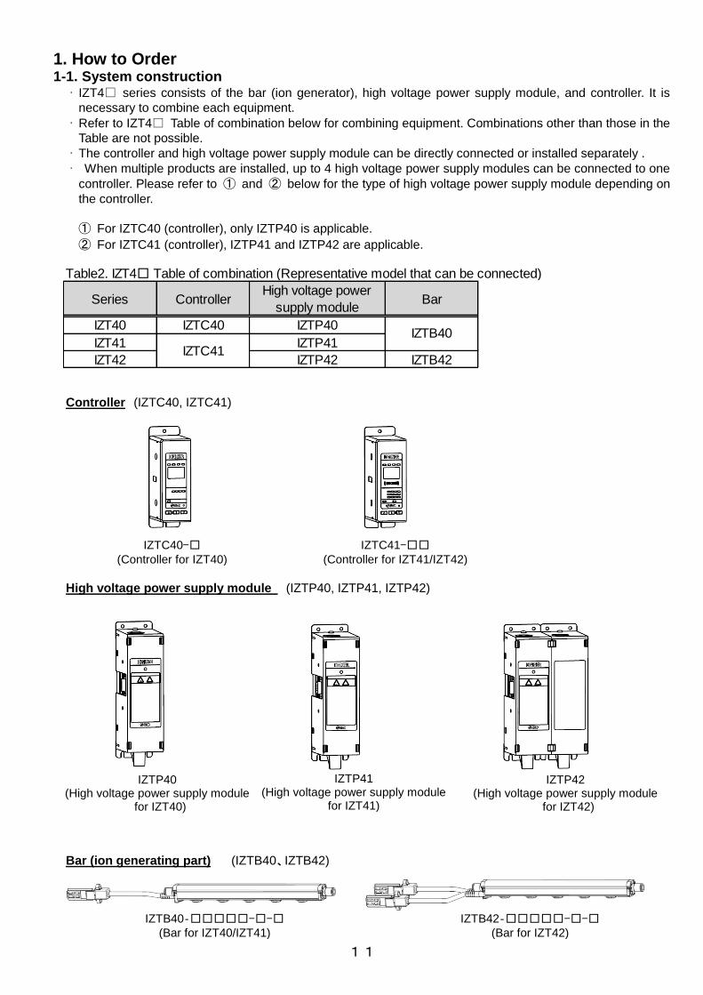
1. How to Order 1-1. System construction · IZT4□ series consists of the bar (ion generator), high voltage power supply module, and controller. It is
necessary to combine each equipment.
· Refer to IZT4□ Table of combination below for combining equipment. Combinations other than those in the
Table are not possible.
· The controller and high voltage power supply module can be directly connected or installed separately .
· When multiple products are installed, up to 4 high voltage power supply modules can be connected to one
controller. Please refer to ① and ② below for the type of high voltage power supply module depending on
the controller.
① For IZTC40 (controller), only IZTP40 is applicable.
② For IZTC41 (controller), IZTP41 and IZTP42 are applicable.
Controller (IZTC40, IZTC41)
High voltage power supply module (IZTP40, IZTP41, IZTP42)
Bar (ion generating part) (IZTB40、IZTB42)
IZTC40-□ (Controller for IZT40)
IZTC41-□□ (Controller for IZT41/IZT42)
IZTP40 (High voltage power supply module
for IZT40)
IZTP41 (High voltage power supply module
for IZT41)
IZTP42 (High voltage power supply module
for IZT42)
IZTB40‐□□□□□-□-□
(Bar for IZT40/IZT41)
IZTB42‐□□□□□-□-□
(Bar for IZT42)
Table2. IZT4□ Table of combination (Representative model that can be connected)
Series ControllerHigh voltage power
supply moduleBar
IZT40 IZTC40 IZTP40
IZT41 IZTP41
IZT42 IZTP42 IZTB42IZTC41
IZTB40

12
Direct connection
Example of connecting IZTC41, IZTP41 and IZTB40 (IZT41)
Example of connecting IZTC40, IZTP40 and IZTB40 (IZT40)
Example of connecting IZTC41, IZTP42 and IZTB42 (IZT42)
Example of connecting IZTC40, IZTP40 and IZTB40 (4pcs.)
Example of connecting IZTC41, IZTP41 and IZTB40 (4pcs.)
Example of connecting IZTC41, IZTP42 and IZTB42 (4pcs.)

13
Separate connection
Example of connecting IZTC40, IZTP40 and IZTB40 (4pcs.)
Example of connecting IZTC40, IZTP40 and IZTB40 (IZT40)
Example of connecting IZTC41, IZTP41 and IZTB40 (4pcs.)
Example of connecting IZTC41, IZTP42 and IZTB42 (4pcs.)
Example of connecting IZTC41, IZTP41 and IZTB40 (IZT41)
Example of connecting IZTC41, IZTP42 and IZTB42 (IZT42)

14
1-2. How to Order · The product number consists of the controller, high voltage power supply module and bar (1 of each).
· When multiple high voltage power supply modules and bars are added to one controller, choose the equipment according to the product number for a single unit.
Bar + High voltage power supply module + Controller
40 34 D 1 6H R 3 F U
42 34 D 1 6H R 3 F UIZT - - -
| |
IZT - - -
|| | | | | | |
(2) (3) (4) (5) (6) (7) (8) (9) (10) (11) (12)
(1)
(1) Model
Symbol
40
Model
Standard type
Symbol
41
42
Model
AC type
Dual AC type
(2) Model
Symbol
16
22
34
40
46
58
64
Symbol
82
1900
2320
2500
(3) Bar length
Bar length (mm)
820
1120
1300
1600
250
Bar length (mm)
160
220
340
400
460
580
640
112
130
160
190
232
(6) One-touch Fitting
Symbol
4H
6H
AL
Metric size
ø4 straight
ø6 straight
ø8 straight
ø10 straight
ø4 elbow
ø6 elbow
ø8 elbow
ø10 elbow
8H
AH
4L
6L
8L
5L
7L
9L
BL
Inch size
ø3/16" straight
ø1/4" straight
ø5/16" straight
ø3/8" straight
ø3/16" elbow
ø1/4" elbow
ø5/16" elbow
ø3/8" elbow
Symbol
5H
7H
9H
BH
※Refer to the bore size in the table below for selection of
One-touch fittings.
P PNP
※None of the Input/Output functions can be used when the
AC adapter is being used.
(8) Input/ Output Speicifications
Symbol Input/ Output
Nil NPN
(4) Emitter Cartridge Type/ Materials
Energy saving static
neutralization cartridge
Tungsten
Silicon
Tungsten
Silicon
Symbol
D
L
E
M
Type Material
High speed static
neutralization cartridge
(9) Power Supply Cable Length
Symbol Length (m)
3 3
5 5
※To use AC adapter, specify "N", and select AC adapter with
the option number.
10 10
15 15
[N] None
(10) Bracket for bar
※Number of intermediate bracket depends on the bar length.
(See table below)
Symbol
Nil
B
F
Type
Without Bracket
With bracket 1
With bracket 2
2
3
No of bracket
End bracket
2,440 to 2,500
1,660 to 2,380
820 to 1,600
160 to 760
Intermediate bracketBar length mm
2
None
1
R
Plug location
Without plug
High voltage cable side
The opposite side of the high voltage cable
(7) Plug Location
Symbol
Nil
Q
(11) DIN rail bracket for controller, high voltage power
supply module
Symbol
Nil
For high v oltage power supply module
None
Included
None
Included
U
W
Y
For controller
None
Included
Included
None
(12) Made to Order
160 220 340 400 460 580 640 820 1120 1300 1600 1900 2320 2500
○ ○ ● ● ● - - - - - - - - -
○ ○ ○ ○ ○ ○ ● ● ● - - - - -
○ ○ ○ ○ ○ ○ ○ ○ ● ● ● ● - -
○ ○ ○ ○ ○ ○ ○ ○ ○ ○ ○ ● ● ●
○ ○ ○ ○ ● ● ● - - - - - - -
○ ○ ○ ○ ○ ○ ○ ● ● ● - - - -
○ ○ ○ ○ ○ ○ ○ ○ ● ● ● ● - -
○ ○ ○ ○ ○ ○ ○ ○ ○ ○ ○ ● ● ●
○: With piping on one side
●: With piping on both sides
IZT4□ Recommended piping bore size
Bar length (mm)
4H / 4L
6H / 6L
8H / 8L
AH / AL
5H / 5L
7H / 7L
9H / 9L
BH / BL
ø4
ø6
ø8
ø10
ø3/16
ø1/4
ø5/16
ø3/8
Symbol for One-
touch fitting
Applicable tubing
O.D. (mm)
Number of High Voltage Cable Holder
※Number of included cable holder is different depending on
the high voltage cable length (Table below).
IZT41 IZT42
StraightSymbol
IZT40
Elbow Straight Elbow Straight Elbow
1
2
3
1
2
3
1
1
2
4
6
2
2
21
1
2
3
1
1
1
Symbol
1
2
3
High voltage cable length (m)
1
2
3
(5) High voltage cable length
15
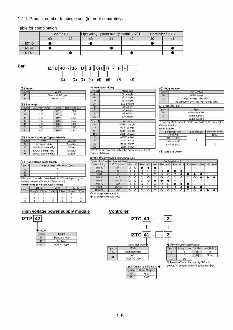
1-2-1. Product number for single unit (to order separately) Table for combination Bar
42IZTP
● Model
42
Model
Standard type
AC type
Dual AC type
Symbol
40
41
40 3
41 3
| |
IZTC -
IZTC -
● Power supply cable length
※To use AC adapter, specify "N", and
select AC adapter with the option number.
Symbol
15
[N]
15
None
Length (m)Symbol
3
5
10
Length (m)
3
5
10
40
41AC,
Dual AC type
Standard type
Model
Controller type ●
Symbol
Symbol
Nil
P
Input / output specifications ●
Input/ Output
NPN
PNP
High voltage power supply module Controller
41
IZT40 ● ● ●
Bar / IZTB High voltage power supply module / IZTP Controller / IZTC
40 42 40 41 42 40
●
IZT42 ● ● ●
IZT41 ● ●
40 16 D 1 6H R FIZTB - - -
(1) (2) (3) (4) (5) (6) (7) (8)
(1) Model
Symbol Model
40 Standard, AC type
42 Dual AC type
58 580 232 2320
64 640 250 2500
40 400 160 1600
46 460 190 1900
22 220 112 1120
34 340 130 1300
(2) Bar length
Symbol Bar length (mm) Symbol Bar length (mm)
16 160 82 820
L Energy saving static
neutralization cartridge
Tungsten
M Silicon
(3) Emitter Cartridge Type/ Materials
Symbol Type Material
D High speed static
neutralization cartridge
Tungsten
E Silicon
23 3 1 3 1 6
2
2 2 1 2 1 4 2
Straight Elbow Straight Elbow
1 1 1 1 1 2
3 3
※Number of included cable holder is different depending on
the high voltage cable length (Table below).
Number of High Voltage Cable Holder
SymbolIZT40 IZT41 IZT42
Straight Elbow
Symbol High voltage cable length (m)
1 1
2 2
(4) High voltage cable length
BL ø3/8" elbow
※Refer to the bore size in the table below for selection of
One-touch fittings.
5L ø3/16" elbow
7L ø1/4" elbow
9L ø5/16" elbow
7H ø1/4" straight
9H ø5/16" straight
BH ø3/8" straight
AL ø10 elbow
Symbol Inch size
5H ø3/16" straight
4L ø4 elbow
6L ø6 elbow
8L ø8 elbow
6H ø6 straight
8H ø8 straight
AH ø10 straight
(5) One-touch Fitting
Symbol Metric size
4H ø4 straight Nil Without plug
Q High voltage cable side
R The opposite side of the high voltage cable
(6) Plug location
Symbol Plug location
160 to 760
2
None
820 to 1,600 1
1,660 to 2,380 2
2,440 to 2,500 3
F With bracket 2
※Number of intermediate bracket depends on the bar length.
(See table below)
No of bracket
Bar length mm End bracket Intermediate bracket
(7) Bracket for bar
Symbol Type
Nil without Bracket
B With bracket 1
(8) Made to Order
160 220 340 400 460 580 640 820 1120 1300 1600 1900 2320 2500
○ ○ ● ● ● - - - - - - - - -
○ ○ ○ ○ ○ ○ ● ● ● - - - - -
○ ○ ○ ○ ○ ○ ○ ○ ● ● ● ● - -
○ ○ ○ ○ ○ ○ ○ ○ ○ ○ ○ ● ● ●
○ ○ ○ ○ ● ● ● - - - - - - -
○ ○ ○ ○ ○ ○ ○ ● ● ● - - - -
○ ○ ○ ○ ○ ○ ○ ○ ● ● ● ● - -
○ ○ ○ ○ ○ ○ ○ ○ ○ ○ ○ ● ● ●
○: With piping on one side
●: With piping on both sides
IZT4□ Recommended piping bore size
7H / 7L ø1/4
9H / 9L ø5/16
BH / BL ø3/8
8H / 8L ø8
AH / AL ø10
5H / 5L ø3/16
Symbol for One-
touch fitting
Applicable tubing
O.D. (mm)
Bar length (mm)
4H / 4L ø4
6H / 6L ø6

16
40 52 D 1 6H R F X10
42 52 D 1 6H R F X10
40 52 D 1 6H R F X10
IZT - - -
IZT - - -
IZTB - - -
41
Model ●40
42
※Only bar is
ordered, 41 cannot
be selected.
※
Standard product number
● Bar length
208 2080
214 2140
220 2200
Symbol Bar length (mm)
196 1960
202 2020
154 1540
1660
172 1720
1240
136 1360
1420
148 1480
1780
1840
226 2260
238 2380
244 2440
940
1000
1060
1180
166
184
178
118
Bar length (mm) Symbol
142
280
520
700
760
880
Bar length (mm)
124
76
88
94
100
106
Symbol
28
52
70
40 34 D 1 6H R F X14
42 34 D 1 6H R F X14
40 34 D 1 6H R F X14
IZT - - -
IZT - - -
IZTB - - -
41
Model ●40
42
※Only bar is
ordered, 41 cannot
be selected.
※
Standard product number
16 22 34 40 46 58 64 82 112 130 160 190 232 250
160 220 340 400 460 580 640 820 1120 1300 1600 1900 2320 2500Standard
Non-standard
● Bar length
Symbol
Length (mm)
The bar of non-standard length is available. Refer to the how to order above.
1-2-2. Made to Order
Bar + High voltage power supply module + Controller
Bar
Bar + High voltage power supply module + Controller
Bar
Symbol
Manufacturable bar length (Symbol) : 10+6×n (n is an integer from 1 to 39)
(Use standard product when n is 1, 2, 4, 5, 6, 8, 9, 12, 17, 20, 25, 30, 37)Non-standard bar length
Description Specifications
-X10
-X14 With emitter cartridge drop prevention cover An optional drop prevention cover is mounted to the ionizer as default.
Description SpecificationsSymbol

17
1-2-3. Accessories (ordered separately)
Emitter Cartridge (Common for IZT40,IZT41,IZT42)
Power supply cable (Common for IZT40, IZT41, IZT42)
Bracket for bar (Common for IZT40, IZT41, IZT42)
カートリッジ色
ホワイト
グレー
エミッタ材質
タングステン
シリコン
IZT40 - N D
● Emitter Cartridge Type/ Materials
L
M
Energy saving static
neutralization cartridge
Symbol
D
E
High speed static
neutralization cartridge
Type
Tungsten
Material
Silicon
Tungsten
Silicon
Cartridge color
White
Gray
Emitter material
Tungsten
Silicon
IZT40 - 3CP
Length (m)
3
5
10
15
Symbol
3
5
10
15
● Power supply cable length
IZT40-BE1 End Bracket 1
IZT40-BE2 End Bracket 2
IZT40-BM1 Intermediate bracket 1
IZT40-BM2 Intermediate Bracket 2
IZT40 - B E1
E2
M1
M2
End bracket 2
Intermediate bracket 1
Intermediate bracket 2
Symbol
E1 End bracket 1
Type
● Bracket for bar
○ : Possible to combine × : Not possible to combine
Table3. Bracket combination
End bracket 1
End bracket 2
Intermediate bracket 1 Intermediate bracket 2
○(angle adjustment +/-90o) ×
× ○(angle adjustment +/-15o)
※Select bracket referring to the combination in the table below.
Table4. No of bracket
※The following table lists the number of bracket required for
intermediate support based on the bar length.
Bar length mm
160 to 760
820 to 1,600
1,660 to 2,380
2,440 to 2,500
2 end brackets are necessary regardless of the bar length.
End bracket Intermediate bracket
2
3
2
1
None

18
DIN rail mounting bracket for controller and high voltage power supply module (Common for IZT40, IZT41, IZT42)
High voltage cable holder (Common for IZT40, IZT41, IZT42)
1-2-4. Sold separately AC adapter (Common for IZT40, IZT41, IZT42)
IZT40 - E 1
● High voltage cable holder
2 Elbow
Symbol
1
Type
Straight
IZT40 - 1CG
TypeSymbol
● AC adapter
1
2
with AC cord
without AC cord
IZT40-E1 High voltage cable holder (straight)
IZT40-E2 High voltage cable holder (elbow)
AC adapter
AC cord
IZT40-B1
Controller DIN rail bracket
IZT40-B2 High voltage power supply module
DIN rail mounting bracket for IZTP40/IZTP41
IZT40-B3 High voltage power supply module
DIN rail mounting bracket for IZTP42
IZT40 - B 1
● DIN rail mounting bracket
2
3
High voltage power supply module for IZT40/IZT41
High voltage power supply module for IZT42
Symbol
1 For controller
Type

19
Drop prevention cover (Common for IZT40, IZT41,IZT42)
Separate cable (Common for IZT40, IZT41, IZT42)
Emitter cleaning kit (Common for IZT40, IZT41, IZT42)
IZT40 - 1CF
2
3 3
● Separate cable length
Length (m)
1
2
Symbol
1
IZS30 - M2 IZS30 - A0201 IZS30 - A0202 (Provided together with 1 felt pad grindstone, 1 rubber grindstone,
and 2 replacement felt pads)
(Provided together with 10 replacement felt pads)
(Provided together with 1 replacement rubber grindstone)
IZS40 - E 2
● No. of emitter cartridge to be fixed
For 2pcs.
Type
For 3pcs.
For 4pcs.
For 5pcs.
4
5
Symbol
2
3 Image of the cover mounted
to the unit
IZS40-E5 Drop prevention cover 5pcs.
IZS40-E2 IZS40-E3 IZS40-E4 IZS40-E5 IZS40-E3 IZS40-E4 IZS40-E5 IZS40-E3 IZS40-E4 IZS40-E5
16 1 - - - 28 - 1 - 154 - - 5
22 - 1 - - 52 1 - 1 166 1 1 4
34 - - - 1 70 2 - 1 172 1 - 5
40 - 2 - - 76 1 1 1 178 - 1 5
46 - 1 1 - 88 - 1 2 184 - - 6
58 - - 1 1 94 - - 3 196 1 1 5
64 - - - 2 100 2 - 2 202 1 - 6
82 - 1 - 2 106 1 1 2 208 - 1 6
112 - 1 - 3 118 - 1 3 214 - - 7
130 - 2 - 3 124 - - 4 220 2 - 6
160 - 2 - 4 136 1 1 3 226 1 1 6
190 - 2 - 5 142 1 - 4 238 - 1 7
232 - 1 - 7 148 - 1 4 244 - - 8
250 - 2 - 7
No. of drop prevention cover neededNo. of drop prevention cover needed Symbol
for bar
length
No. of drop prevention cover needed Symbol
for bar
length
Symbol
for bar
length
Table5. Standard bar length Table6. Non-standard bar length

20
Start
Installation of ionizer body
Wiring of ionizer
Air purge Piping of ionizer
Pressure setting
Initial setting
Adjustment of offset voltage (ion balance)
Completed
High voltage power supply module CH number setting
Yes
No.
Power supply is ON
Frequency setting
2. Procedures to Operation 2-1. Flow chart to operation
2-2. Initial setting (Initial setting is not necessary for IZT40) · This product has a function which constantly monitors the emitter contamination. When emitter
contamination is detected, it is indicated by a signal output and LED. Initial setting is necessary for emitter contamination detection.
· In the default setting "no" is displayed for the frequency display.
· The Initial setting is started by pressing the S button for 3 seconds or longer while "no" is displayed. To revert to the default setting press the reset button during use.
· Connect and install the ionizer bar to be used before setting.
· When multiple bars are connected, assign the channel for which initial setting is necessary. Refer to 4-4-2. Channel selection mode for channel setting.
· Do not disconnect the power supply during setting. (Initial setting is completed within 60 seconds.) [Initial setting is necessary in following cases]
① When "no" is displayed in the frequency display.
② Bar is replaced.
③ Installation environment is changed.
※For ②③, perform initial setting after pressing the reset button
and make sure that "no" is displayed in the frequency display.
It is recommended to start the initial setting for ③ after
replacing the emitter cartridge. If initial setting is performed while the emitter cartridge is not clean or is worn out, emitter contamination detection may not work properly.
Refer to 3-1. Installation of Ionizer for details.
Refer to 3-2.Wiring.
Refer to 3-1. Installation of Ionizer for details.
Caution: Do not adjust the flow using the restrictor. Refer to 3-1-2. Adjustment of Pressure (Flow adjustment).
Refer to 4-3. High voltage power supply module CH number setting.
Refer to 4-4-3. Frequency set mode.
Refer to 4-4-4. Adjustment mode of Offset Voltage
Refer to 2-2.Initial setting.( Initial setting is not necessary for IZT40)
Controller (IZTC41)
Frequency
display
Reset button

21
3. Installation and wiring · The performance of the product varies depending on the surrounding installation and operating conditions. It
is recommended to investigate in advance any processes and parts where static electricity disturbances occur. Verify that the required conditions have been met in order to effectively remove static electricity before installation.
· After installation, verify the performance of this product.
3-1. Installation of Ionizer 3-1-1. Precautions for Installation
· Be sure to stop power supply and air supply to the product before starting the product installation.
· Do not affix any tape or labels to the bar. Dielectric phenomenon may occur due to ions arising from such substances, resulting in electrostatic charging or electric leakage.
3-1-2. Adjustment of Pressure (Flow adjustment)
· When air is supplied to the bar, adjust the flow using a regulator which should be connected immediately before the bar. If a flow adjustment valve is used between the bar and regulator , the speed of the flow from the nozzle decreases due to the pressure decrease , decreasing the neutralizing performance.
· Check the pressure around the bar air supply port. A pressure difference may be generated between the regulator pressure and the pressure at the bar air supply port due to the supply piping length and piping diameter. If a pressure gauge with regulator is used for checking the pressure, use a large capacity regulator, keep the piping as short as possible or make the piping diameter larger.
· When installing a flow meter to the air circuit, refer to “5-4. Flow - Pressure characteristics” to choose the product type so that the flow of the bar does not exceed the flow meter rated flow range. If the bar's flow consumption is larger than the rated flow of the selected flow meter, the flow supplied to the bar is limited, thus deteriorating neutralization performance.
3-1-3. Selection of piping port size
· When air is supplied, choose the ionizer piping fitting referring to the table [One-touch fitting selection] . · Connect piping for air supply through the One-touch fitting(s) either to one end or both ends depending on
the bar length.
· If a tube is used which is thicker than the recommended tube, neutralization performance will be deteriorated due to a shortage of air flow.
Piping port Piping port
Flow adjustment valve
Bar
Pressure check
Pressure regulator
Bar
Flow meter

22
One-touch fitting selection (Standard bar length)
· Selection of bar length which is not standard Choose the same pipe that is longer than the selected bar and the closest standard length bar.
Example 1) Bar length 1000 mm, one-touch fitting symbol "8H" (tube O.D. ø8) With piping on both sides. refer to the table above.
Example 2) Bar length 1360 mm, with piping on one side.
Use AH/AL or BH/BL (refer to the table above).
3-1-4. Distance for installation
· Refer to the table below for the recommended distance between the ionizer and object to be neutralized.
※The above mentioned distances are guidelines for installation of the ionizer. Confirm
the de-ionizing effect before installing.
3-1-5. Installation of bracket for bar
· 2 types of end bracket and intermediate bracket are available. When end bracket 1 is used, use intermediate bracket 1. For end bracket 2, use intermediate bracket 2.
1)End bracket · Use specified end bracket.
· For mounting, fix the end bracket at both ends of the bar using M4 screws with the specified tightening torque.
Tightening torque: 0.51 to 0.55 Nm
IZT40-BE1 End bracket 1
M4 screw
IZT40-BE2 End bracket 2 M4 screw
160 220 340 400 460 580 640 820 1120 1300 1600 1900 2320 2500
○ ○ ● ● ● - - - - - - - - -
○ ○ ○ ○ ○ ○ ● ● ● - - - - -
○ ○ ○ ○ ○ ○ ○ ○ ● ● ● ● - -
○ ○ ○ ○ ○ ○ ○ ○ ○ ○ ○ ● ● ●
○ ○ ○ ○ ● ● ● - - - - - - -
○ ○ ○ ○ ○ ○ ○ ● ● ● - - - -
○ ○ ○ ○ ○ ○ ○ ○ ● ● ● ● - -
○ ○ ○ ○ ○ ○ ○ ○ ○ ○ ○ ● ● ●
Table7. Recommended piping bore size
Bar length (mm)
4H / 4L
6H / 6L
8H / 8L
φ 4
φ 6
φ 8
Symbol for One-
touch fitting
Applicable tubing
O.D. (mm)
○: With piping on one side
●: With piping on both sides
AH / AL
5H / 5L
7H / 7L
9H / 9L
BH / BL
φ 10
φ 3/16
φ 1/4
φ 5/16
φ 3/8
Table8. Ion generating frequency and distance for installation
0.1 - - - 100~175 50 to 2,000 50 to 2,000
0.5 - - - 100~175 50 to 2,000 50 to 2,000
1 300 to 500 400 to 2,000 600 to 2,000 100 to 175 50 to 2,000 50 to 2,000
3 300 to 400 350 to 2,000 500 to 2,000 75 to 150 50 to 2,000 50 to 2,000
5 300 to 400 300 to 2,000 400 to 2,000 75 to 150 50 to 2,000 50 to 2,000
8 300 to 350 250 to 2,000 300 to 2,000 75 to 150 50 to 2,000 50 to 2,000
10 200 to 300 200 to 2,000 200 to 2,000 75 to 150 50 to 2,000 50 to 2,000
15 200 to 300 150 to 2,000 100 to 2,000 50 to 125 50 to 2,000 50 to 2,000
20 150 to 250 100 to 2,000 50 to 2,000 50 to 125 50 to 2,000 50 to 2,000
30 50 to 200 50 to 2,000 50 to 2,000 50 to 125 50 to 2,000 50 to 2,000
Energy saving static
neutralization cartridge
High speed static
neutralization cartridge
Ion
generating
frequency
[Hz]
Distance from the ionizer to the de-ionized workpiece [mm]
IZT40,IZT41 IZT42
Without air
purge
With air purgeWithout air
purge
With air purge
Energy saving static
neutralization cartridge
High speed static
neutralization cartridge

23
2) Intermediate bracket (for bar lengths of 820mm or more)
· Match the groove of the bar and protrusion of the intermediate bracket, and slide the bracket from the end of the bar.
· Intermediate brackets should be mounted at the same intervals.
3) Installation of the bar
· Fix the bracket to the specified position using M5 screws.
· Refer to "6. Dimensions" section for details. (The screws should be prepared by the user).
4)Mounting angle adjustment · Adjust the mounting angle of the bar for effective neutralization, and fix the product with the rotating set
screw (M4 ) at each bracket.
Tightening Torque IZT40-BE1 (End bracket 1) : 0.72 to 0.76Nm IZT40-BE2 (End bracket 2) : 0.72 to 0.76Nm IZT40-BM1 (Intermediate bracket 1) : 0.72 to 0.76Nm IZT40-BM2 (Intermediate bracket 2) : 0.47 to 0.49Nm
3-1-6. Connecting the controller and high voltage power supply module
· Remove the protection film on the controller before use.
· The product is used by connecting the controller and high voltage power supply module. They can be connected either directly or separately. For separate connection, an optional separate cable is required.
· Mount a dust cover on the D-sub connector when not using the directly mounted high voltage power supply module.
IZT40-BM1 Intermediate bracket 1
IZT40-BM2 Intermediate bracket 2
M5 screw
IZTB40/IZTB42 Bar
M5 screw
90o
IZT40-BE1
End bracket 1
IZT40-BM1
Intermediate bracket 1
IZT40-BE2
End bracket 2 IZT40-BM2
Intermediate bracket 2
M4 screw M4 screw
90o
15o 15
o

24
1)Direct connection
· Fix the controller and high voltage power supply module using cross recessed round head screw (M4x30).
Tightening Torque: 0.22 to 0.24Nm
2)Separate connection
· For separate connection, an optional separate cable is required.
· Mount the spacers (included) to fix the separate cable to the high voltage power supply module. Fix the spacers (2 pcs.) to the plug (male side) of the D-sub connector on the high voltage power supply module.
· Connect the controller and high voltage power supply module after mounting the spacers and fix them using 2 round head combination screws (M2.6).
Spacer tightening torque: 0.4 to 0.6 Nm Separate cable tightening torque: 0.25 to 0.35 Nm
Dust cover (Included)
M4 screw (Included)
IZTC40, IZTC41 Controller (Figure shows IZTC41)
IZTP40, IZTP41, IZTP42
High voltage power supply module (Figure shows IZTP41)
M2.6 screw
M2.6 screw
IZTC40、IZTC41
Controller (Figure shows IZTC40)
IZT40-CF□
Separate cable
IZTP40、IZTP41、IZTP42
High voltage power supply module (Figure shows IZTP40)
Spacer (Included)
D-sub connector socket
D-sub connector plug

25
3)Connecting multiple units.
· Up to 4 controllers and high voltage power supply modules can be connected together.
· Controller IZTC40 can be connected to IZTP40 only.
· Controller IZTC41 can be connected when IZTP41 and IZTP42 are used together, but IZTP40 cannot be connected.
· When multiple controllers are connected, make sure that the displayed content and the number of connected controller is consistent after power is supplied.
(Connected CH turns on or flashes)
3-1-7. Installing the controller and high voltage power supply module
· Install the controller and high voltage power supply module to DIN rail using screws or DIN rail mounting brackets. 1) Mounting with screws (The screws should be prepared by the user).
· Fix the controller (IZTC40 and IZTC41) using 2x M4 screws.
· Fix the high voltage power supply module controller (IZTP40 and IZTP41) using 4x M4 screws.
· Fix the high voltage power supply module controller (IZTP42) using 8x M4 screws.
· The number of screws to connect multiple high voltage power supply modules = Number of connected modules x screws necessary for fixing a module.
Ⅰ. When the controller and high voltage power supply module are directly connected
· Install the directly connected controller and high voltage power supply module at location B using M4 screws.
· Refer to 6. Dimensions for details. (The screws should be prepared by the user).
When IZTC41 and IZTP42 are directly connected.
B : M4screw
B : M4screw
When IZTC41 and IZTP41 are directly connected.
B : M4screw
B : M4screw
Direct connection Example of connecting IZTC40,
IZTP40 and IZTB40 (4pcs.)
Separate connection Example of connecting IZTC41, IZTP42 and IZTB42 (4pcs.)

26
Ⅱ. When the controller and high voltage power supply module are connected separately
· Mount the spacers to the high voltage power supply module. Refer to 3-1-6. Connect the controller and high voltage power supply Module.
· Install the separately connected controller and high voltage power supply module by at location B using M4 screw (x 6).
· Refer to 6. Dimensions for details. (The screws should be prepared by the user).
Ⅲ.Adding a high voltage power supply module a. High voltage power supply module to be added should be
· Connected by D-sub connector at location C.
· Controller IZTC40 can be connected to IZTP40 only. Controller IZTC41 can be connected when IZTP41 and IZTP42 are used together, but IZTP40 cannot be connected.
b. Mounting bracket
· Mount the brackets to location D.
c. Install the controller and high voltage power supply module
· Fix the controller and high voltage power supply module at location B using M4 screw.
· Refer to "6. Dimensions" section for details. (The screws should be prepared by the user).
d. High voltage power supply module CH number setting
· Set the CH number so that it does not duplicate the set number of other channels. Refer to 4-3. High voltage power supply module CH number setting. If duplicated, it will be verified as an error. Refer to "4-5. Alarms" for further details.
2) Installation of DIN rail · Use an optional DIN rail mounting bracket.
· DIN rail mounting brackets are required for mounting the controller and high voltage power supply module.
· Tighten the fixing brackets that are installed and shipping with specified torque before installation.
Ⅰ. When the controller and high voltage power supply module are directly connected
a. Removal of the fixing bracket
· Remove the fixing bracket from the DIN rail mounting bracket at the adjoining faces indicated at location E.
b. DIN rail mounting bracket
· Fix the controller and high voltage power supply module to the DIN rail mounting bracket using M4 screws.
Tightening Torque: 1.30 to 1.50 Nm
D : Brackets(accessories)
C : D-sub connector
B: M4 thread
B: M4 thread
B : M4 thread B : M4 thread
B : M4 thread
B : M4 thread
27
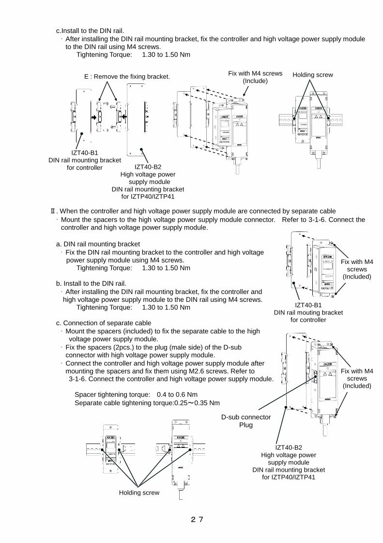
c.Install to the DIN rail.
· After installing the DIN rail mounting bracket, fix the controller and high voltage power supply module to the DIN rail using M4 screws.
Tightening Torque: 1.30 to 1.50 Nm
Ⅱ. When the controller and high voltage power supply module are connected by separate cable
· Mount the spacers to the high voltage power supply module connector. Refer to 3-1-6. Connect the controller and high voltage power supply module.
a. DIN rail mounting bracket
· Fix the DIN rail mounting bracket to the controller and high voltage power supply module using M4 screws.
Tightening Torque: 1.30 to 1.50 Nm
b. Install to the DIN rail.
· After installing the DIN rail mounting bracket, fix the controller and high voltage power supply module to the DIN rail using M4 screws.
Tightening Torque: 1.30 to 1.50 Nm c. Connection of separate cable
· Mount the spacers (included) to fix the separate cable to the high voltage power supply module.
· Fix the spacers (2pcs.) to the plug (male side) of the D-sub connector with high voltage power supply module.
· Connect the controller and high voltage power supply module after mounting the spacers and fix them using M2.6 screws. Refer to 3-1-6. Connect the controller and high voltage power supply module.
Spacer tightening torque: 0.4 to 0.6 Nm
Separate cable tightening torque:0.25~0.35 Nm
Fix with M4 screws (Include)
Fix with M4 screws
(Included)
IZT40-B1 DIN rail mouting bracket
for controller
Holding screw
D-sub connector Plug
IZT40-B2 High voltage power
supply module DIN rail mounting bracket
for IZTP40/IZTP41
Fix with M4 screws
(Included)
Holding screw
IZT40-B2 High voltage power
supply module DIN rail mounting bracket
for IZTP40/IZTP41
E : Remove the fixing bracket.
IZT40-B1 DIN rail mounting bracket
for controller

28
Ⅲ. When the high voltage power supply module is added directly
a. Removal of the fixing bracket
· Remove the fixing bracket from the DIN rail mounting bracket at the adjoining faces indicated at location E.
b. Mounting of DIN rail mounting bracket
· Fix the controller and high voltage power supply module to the DIN rail mounting bracket using M4 screws .
Tightening Torque: 1.30 to 1.50 Nm
c. Connect the controller and high voltage power supply module
· Connect the D-sub connector in location C and fix the controller and high voltage module together using M4x30 screws (2 pcs. included as an accessory).
Tightening Torque: 0.22 to 0.24 Nm
C : D-sub connector
IZT40-B1 DIN rail mounting bracket
for controller
Fix with M4 screws (Included)
Addition of module
M4x30 (Included)
IZT40-B2 High voltage power
supply module DIN rail mounting bracket
for IZTP40/IZTP41
Fix with M4 screws
(Included)
IZT40-B2 High voltage power
supply module DIN rail mounting bracket
for IZTP40/IZTP41
Fix with M4 screws
(Included)
E. Remove the fixing bracket

29
d. Install to DIN rail
· Mount them on to the DIN rail and connect the additional high voltage power supply module D-sub connector.
e. Mount the fixing bracket
· Mount the fixing brackets (included as an accessory) in location D.
f. Fix to DIN rail
· After installing to the DIN rail, fix the controller and high voltage power supply module using set screws.
Tightening Torque: 1.30 to 1.50 Nm
g. High voltage power supply module CH number setting
· Set the CH number setting switch for all connected high voltage power supply modules.
· Set the CH number so that it does not duplicate the set number of other channels.
(Refer to 4-3. High voltage power supply module CH number setting.) If duplicated, it will be verified as an error.
(Refer to 4-5. Alarms for details.)
High voltage power supply module to be added
D-sub connector
D : Fixing bracket
High voltage power supply module to be added
Holding screw
Change the CH setting for multiple connection.
(Default CH switch setting is "1".)
CH set switch High voltage power supply module

30
3-1-8. Routing of cables
· Do not apply excess stress to the mounting part of the connector.
· When the cable is bent, maintain the minimum bend radius.
Minimum bending radius: Power supply cable: 40 mm Separate cable: 40 mm High voltage cable: 30 mm
※ Separate cable is optional.
1) Power supply cable
· This cable supplies power to the ionizer and external equipment used to control the ionizer. (IZT40 has no input/output functions.)
· When connecting the controller to the power supply cable, insert it until it makes a click sound.
· When removing the power supply cable, press the plug claw to release the lock and pull it out straight. If mounted or removed in an inappropriate direction, the connector may be damaged and cause operation failure.
· Fix the cable around the connecting part so that stress is not applied to the plug.
· Connect the lead wires according to the wiring diagram. Unused wires should be cut short, or insulated using insulation tape.
· To satisfy the current capacity, make sure to wire 2 brown cables in which a voltage of 24 VDC is supplied and 2 blue cables in which 0V is connected.
2) Separate cable (optional)
· Cable for connecting the controller and high voltage power supply module and connecting extension modules separately. This cable is not necessary when the modules are directly connected.
· Before connecting the cable, mount the spacers (included) in the male side of the D-sub connector plug on the high voltage power supply module. Refer to 3-1-6. Connect the controller and high voltage power supply module.
· It is not necessary to mount spacers to the controller D-sub connector and the D-sub connector (socket) of the high voltage power supply module because spacers are already mounted to them.
· When the separate cable is mounted or removed, pinch the connector with fingers and insert or take out the plug vertically. If mounted or removed in an inappropriate direction, the connector may be damaged and cause operation failure.
· After connecting the separate cable, fix screws of the connector. Mount the dust cover to any D-sub connector which is not used.
Spacer tightening torque: 0.4 to 0.6 Nm Separate cable tightening torque: 0.25 to 0.35 Nm
Power supply cable
Controller
Claw of the plug
IZTC40、IZTC41
Controller (Figure shows IZTC40)
IZT40-CF□
Separate cable
IZTP40、IZTP41、IZTP42
High voltage power supply module (Figure shows IZTP40)
Spacer(Included)
D-sub connector Socket
D-sub connector Plug

31
3)High voltage cable Ⅰ. High voltage cable connection
· Connect the high voltage cable at the bar end to the high voltage power supply module.
· When connecting and disconnecting the high voltage cable, hold the plugs together with the plug bodies, and insert or pull out straight. If mounted or removed in an inappropriate direction, the mounting part of the modular jack may be damaged and cause operation failure.
· Do not touch part A when handling the plug. Be careful so that moisture oil or foreign matter does not adhere to the plug. Adhesion of moisture, oil or foreign matter on part A may cause high voltage electric leakage. If moisture, oil, or foreign matter adheres to part A, clean it with ethanol.
· After connecting the high voltage cable to the high voltage power supply module, fix the cable using 2 cross recessed round head screws (M4x10) included with the product.
Tightening Torque: 0.49 to 0.53 Nm
Ⅱ. Wiring high voltage cable
· When installing the high voltage cable, use the specified high voltage cable holder.
· Refer to "6. Dimensions" section for details.
a. High voltage cable holder (straight)
· Use 2 cross recessed round head screws (M4) for installing the high voltage cable holder. Press the cable positioning it into the holding position and install it. (The screws should be prepared by the user).
Tightening torque: 0.19 to 0.21 Nm
Plug M4 screw
IZTP40, IZTP41, IZTP42 High voltage power supply module
(Figure shows IZTP41)
High voltage cable
M4 screw IZT40-E1
High voltage cable holder
(straight) High voltage cable
Holding position
High voltage connector
(裏面)
A
A

32
b. High voltage cable holder (elbow)
· Use the cable holder when bending the high voltage cable through 90 degree.
· Use 2 holders when installing high voltage cable for the IZT42.
· Use cross recessed round head screws (M4) for fixing the high voltage cable holder.
· When they are used in layers, select the screw length considering the thickness of the high voltage cable holder (14.8 mm/holder).
· When holding the high voltage cable to the cable holder, align the cable in the holding position and mount it by pressing the cable. (The screws should be prepared by the user).
Installation example 1
Installation example 2
Installation example 3
M4 screw
IZT40-E2
High voltage cable holder
(elbow)
M4 screw
High voltage cable
Holding position
Holding position
M4 screw
IZT40-E2
High voltage cable holder
(elbow)
Holding position
High voltage cable
M4 screw
IZT40-E2
High voltage cable holder
(elbow)
High voltage cable
Holding position
High voltage cable

33
3-2. Wiring · Wire power cables according to the connection circuit and wiring chart.
3-2-1. Ground the ground terminal
· Make sure to ground the ground terminal (F.G.) with a ground resistance of 100Ω or less.
· The ground terminal (F.G.) is used as a reference electric potential for static neutralization. If the F.G. cable is not grounded, an optimal offset voltage (ion balance) cannot be obtained, and it may damage the ionizer and power supply.
3-2-2. Connection Circuit
· Do not apply excess stress to the mounting part of the controller connector.
· When the power supply cable is bent, maintain the minimum bend radius. [Minimum bend radius] : 40 mm
· Connect the lead wires according to the wiring diagram.
· Unused wires should be cut short, or insulated using insulation tape.
· To satisfy the current capacity, make sure to wire 2 brown cables in which a voltage of 24 VDC is supplied and 2 blue cables in which 0V is connected.
1)Wiring of IZTC40
When the product is used in DC mode, make sure to ground the F.G. cable (green) and DC(-) cable (blue) of the input power supply with a resistance of 100 ohms or less. Without grounding the DC(-) cable, the ionizers and/or power supply may be damaged.
+24V Brown (2cables)
DC(+)
Green F.G.
Inte
rna
l cir
cu
it
Controller (IZTC40)
+24 VDC
F.G.
Power supply
F.G.
Shield
Blue (2 cables) DC(-)-
Table9. Wiring
Cable
colorSignal name Signal direction Description
Green F.G. -Make sure to ground with a resistance of 100Ω or less to use it
as a reference electric potential for Ionizer.
Pink Unused - -
Gray Unused - -
Yellow Unused - -
Purple Unused - -
White Unused - -
Black Unused - -
Orange Unused - -
Connect power supply to operate the Ionizer.
DC(+) IN
Blue DC (-) IN
Brown
Power supply

34
2)wiring of IZTC41
NPN type
When an ionizer (IZT41) is used in DC mode, make sure to ground the F.G. cable (green) and DC(-) cable (blue) of the input power supply with a resistance of 100 ohms or less. Without grounding the DC(-) cable, the ionizers and/or power supply may be damaged.
Controller (IZTC41)
Inte
rna
l cir
cu
it
PLC
OUTPUT
INPUTOUTPUT
+24V +24V
DC/DC0V 0V
+24V
+24V
+24V
+24V
+24V
or
or
or
or
Be sure to ground.
Be sure to ground.
+24 VDC
-
F.G.
Power supply24VDC
Shield
Green F.G.
Brown (2cables)
DC(+)
Pink Ion generation stop
CH1
White Maintenance detection signal
Black Error signal
INPUT
Blue (2 cables) DC(-)
Gray Ion generation stop
CH2
Yellow Ion generation stop
CH3
Purple Ion generation stop
CH4
Power supply
Table10. Wiring
Cable
colorSignal name Signal direction Description
Green F.G. -Make sure to ground with a resistance of 100Ω or less to use it
as a reference electric potential for Ionizer.
Pink Ion discharge stop signal CH1 IN
Gray Ion discharge stop signal CH2 IN
Yellow Ion discharge stop signal CH3 IN
Purple Ion discharge stop signal CH4 IN
White Maintenance detection signalOUT
(Contact point A)Turns ON when emitter needs cleaning.
Black Error signalOUT
(Contact point B)
Turns off in case of CPU failure, power supply failure, high voltage failure,
communication failure, cooling fan motor failure, inconsistent module, duplication of CH,
output signal over current, or high voltage power supply module is not connected.
(The signal is ON when there is no problem.)
Orange Unused - -
Connect power supply to operate the Ionizer.
Signal input to turn ON/OFF ion generation of each bar (CH1 to 4).
NPN specification: Ion generation is stopped by connecting to 0 V.
(Ion generation stars by disconnecting)
PNP specification: Ion generation is stopped by connecting to 24 VDC .
(Ion generation stars by disconnecting)
IN
IN
Brown DC(+)
Blue DC (-)
Power supply

35
PNP type
When an ionizer (IZT41) is used in DC mode, make sure to ground the F.G. cable (green) and DC(-) cable (blue) of the input power supply with a resistance of 100 ohms or less. Without grounding the DC(-) cable, the ionizers and/or power supply may be damaged.
3-2-3. Wiring of the AC adapter
· Perform F.G. connecting with the ground terminal (F.G.) of the AC cord when AC adapter is used. If the AC cord is plugged in, plug it into a grounded outlet. Use an AC cord with ground terminal if it is prepared by the user.
· The ground terminal (F.G.) is used as a reference electric potential for static neutralization. If the ground terminal is not grounded, the Ionizer will not be able to achieve the optimal offset voltage (ion balance).
· When an AC adapter is used, the external input/output function cannot be used (Model: IZTC41, IZTC41-P).
AC cord
FG terminal
Controller / IZTC (IZTC41-P)
Inte
rnal circuit
PLC
OUTPUT
INPUT
OUTPUT
+24V +24V
DC/DC0V 0V
+24V
or
or
or
or
Be sure to ground.
Be sure to ground.
+24 VDC
-
F.G.
Power supply24VDC
Shield
Green F.G.
Brown (2cables) DC(+)
Pink Ion generation stop
CH1
White Maintenance detection signal
INPUT
+24V
+24V
Blue (2 cables) DC(-)
Gray Ion generation stop
CH2
Yellow Ion generation stop
CH3
Purple Ion generation stop
CH4
Black Error signal
Power supply

36
3-3. Timing chart 3-3-1. IZT40
1)During operation
Note 1) It takes 3 seconds to operate after the power is on. Note 2) Press the controller button for 2 seconds or longer to stop the ion generation.
To release, press the S button once or turn the power off and on again.
Note 3) 5P flashes. Note 4) Selected bar (high voltage power supply module) ION/HV to display is turned off.
Note 5) Selected bar (high voltage power supply module) stops ion generation.
Operation
Ions are generated (green)
Input
Power supply +24 VDC ―
Controller button
▲ / ▼ / S button―
Display Status
Frequency Hz
CH display
High voltage power supply
module disconnected
Ion generating status
ION/HV
Incorrect high voltage (red)
Key-lock (green) KEY
Dis
pla
y
CH display
Selected CH to display
CH display
CH which display is not
selected
CH
Power ON
ONOFFON
OFF
ON
OFF
ON
OFF
ON
OFF
ON
OFF点灯消灯点灯消灯ON
OFF
Generate
Stop
1Hz
ONOFF
ON
OFF
Power OFF
PowerON
ON
OFF
Note 1)
ON
OFF
ON
Ion generationstop input.Operation
button input.
▲+▼ button
Ion generationstop release.
Operation
button input.S buttonRelease
2s or longer
ON
PowerOFF
PowerON
Ion generationstop input.Operation
button input.
▲+▼ button
Note 2)
Note 1)
2s or longer
Note 2)
1Hz
1HzNote 3)
1HzNote 3)
Note 5) Note 5)
Note 4) Note 4)
Note 2)
Press and hold Press and hold

37
2)Changing the setting mode
Note 6) It takes 3 seconds to operate after the power is on. Note 7) Press the controller button once or for 2 seconds or longer to change/set the setting mode and stop the ion generation.
To release the ion generation, press the S button once or turn the power off and on again. Note 8) Content of each setting mode is displayed by flashing. Refer to [4-4. Controller setting]. Note 9) Selected bar (high voltage power supply module) ION/HV to display is turned off. Note 10) Selected bar (high voltage power supply module) stops ion generation. Note 11) If ON is selected for key lock setting, the setting is held even if the power is turned off and on again.
Display Status
Changing the setting mode
Channel selection mode
↓Frequency set mode
Frequency set mode
↓Offset voltage adjustment mode
Input
Power supply +24 VDC ―
Controller button
▲ / ▼ / S button―
Incorrect high voltage (red)
Frequency Hz
Key-lock (green) KEY
Ion generating status
Dis
pla
y
CH display
Selected CH to display
CHCH display
CH which display is not
selected
CH display
High voltage power supply
module disconnected
Ions are generated (green)
ION/HV
ONOFFON
OFF
ON
OFF
ON
OFF点灯消灯ON
OFF
ON
OFF点灯消灯点灯消灯ON
OFF
ONOFF
ON
OFF
ON ON
ON
OFF
Operation
button input.S button
Operation
button inputS button
Adjustment of theof fset voltage.
Operation
button input.
▲ or ▼ button
Setting change
Frequency selection.Operation
button input.
▲ or ▼ button
Setting change
ON
OFF
ON
Ion generationstop input.Operation
button input.
▲+▼ button
Ion generationstop release.
Operation
button input.S button
Release
2s or longer
ON
Ion generationstop input.Operation
button input.
▲+▼ button
Ion generationstop release.
Operation
button input.S button
Release
2s or longer
Note 9) Note 9)
Note 10) Note 10)
Note 7)
Press and hold Press and hold
Generate
Stop
Display Status
Offset voltage adjustment mode
↓Channel selection mode
Channel selection mode
↓Key-lock setting mode
Changing the setting mode
Input
Power supply +24 VDC ―
Controller button
▲ / ▼ / S button―
Incorrect high voltage (red)
Frequency Hz
Key-lock (green) KEY
Ion generating status
Dis
pla
y
CH display
Selected CH to display
CHCH display
CH which display is not
selected
CH display
High voltage power supply
module disconnected
Ions are generated (green)
ION/HV
ONOFFON
OFF
ON
OFF
ON
OFF点灯消灯ON
OFF
ON
OFF点灯消灯点灯消灯ON
OFF
ONOFF
ON
OFF
ON
OFF
ON
OFF
PowerOFF
PowerONON
Operation
button input.S button
Note 6)
Key-lock setting.Operation
button input.
▲ or ▼ button
Setting change ON
Operation
button input.S button
ON
Operation
button input.S button
Key-lock setting.Operation
button input.
▲ or ▼ button
Setting change ON
Operation
button input.S button
3s or longer 3s or longer
1HzNote 8)
1HzNote 8)
Note 11)
1Hz
ON
Operation
button input.S button
CH selection.Operation
button input.
▲ or ▼ button
Setting change
1HzNote 8)
ON
Ion generationstop input.Operation
button input.
▲+▼ button
Ion generationstop release.
Operation
button input.S button
Release
2s or longer
1HzNote 8)
Note 9)
Note 10)
Note 7)
Press and hold
Generate
Stop
Press and hold Press and hold

38
3)When error occurs
Note 12) It takes 3 seconds to operate after the power is on. Note 13) Abnormality can be released by the ion generation stop signal. Release the error after recovery. Note 14) Frequency of the high voltage power supply module with a problem is displayed by flashing error code.
Refer to [4-5-1. Alarms for IZT40]. High voltage power supply module without problem indicates normal status. Note 15) All ION/ HV of CH1 to 4 flash (red). Note 16) All connected high voltage power supply module ION/HV flash (red). Note 17) High voltage power supply module ION/HV with problem flashes (red). Note 18) High voltage power supply module ION/HV with problem turns on (red). Note 19) The screen at the time of problem occurring holds the status before the problem. Note 20) All the selected bars (high voltage power supply module) stop ion generation. Note 21) Bar with a problem (high voltage power supply module) stops ion generation.
Key-lock (green) KEY
Ion generating status
Dis
pla
y
CH display
Selected CH to display
CHCH display
CH which display is not
selected
CH display
High voltage power supply
module disconnected
Ions are generated (green)
ION/HV
Incorrect high voltage (red)
Frequency Hz
Input
Power supply +24 VDC ―
Controller button
▲ / ▼ / S button―
Incorrect high voltage
Error code:E3
Communication error
Error code:E4
Display Status
CPU failure (controller)
Error code:E0
Power supply failure
Error code:E1
CPU failure
(High voltage power supply module)
Error code:E2
ONOFFON
OFF
ON
OFF
ON
OFF点灯消灯ON
OFF
ON
OFF点灯消灯ON
OFF
Error Error Error
Note 19) Note 19) Note 19)
Error
Note 19)
ONOFF
ON
OFF
PowerOFF
PowerON
PowerOFF
PowerON
PowerOFF
PowerON
ON
OFF
1HzNote 14)
1HzNote14)
1HzNote 14)
1HzNote 14)
1HzNote 15)
1HzNote 16)
1HzNote 17) Note 18)
Error
Note 19)
PowerOFF
PowerON
1HzNote 14)
1HzNote 17)
Note 12) Note 12) Note 12) Note 12)
ON
OFF点灯消灯
1Hz 1Hz 1Hz
Note 20) Note 20) Note 21) Note 21) Note 21)
Note 13) Note 13)
1Hz 1Hz
Generate
Stop
Key-lock (green) KEY
Ion generating status
Dis
pla
y
CH display
Selected CH to display
CHCH display
CH which display is not
selected
CH display
High voltage power supply
module disconnected
Ions are generated (green)
ION/HV
Incorrect high voltage (red)
Frequency Hz
Input
Power supply +24 VDC ―
Controller button
▲ / ▼ / S button―
Fan motor failure
Error code:E5
Inconsistent module
Error code:E6
Duplication of CH
Error code:E7
High voltage power supply module
not connected
Error code:--
Display Status
ONOFFON
OFF
ON
OFF
ON
OFF点灯消灯ON
OFF
ON
OFF点灯消灯点灯消灯ON
OFF
ONOFF
ON
OFF
ON
OFF
ON
OFF
Error
Note 19)
PowerOFF
PowerON
Error
PowerOFF
PowerON
Error
Note 19)Note 19)
1HzNote 14)
1HzNote 14)
1HzNote 14)
1HzNote 17)
1HzNote 17)
1HzNote 17)
Error
PowerOFF
PowerON
1HzNote 14)
Note 12) Note 12) Note 12)
Note 19)
Note 13)
1Hz 1Hz 1Hz
Note 21) Note 21) Note 21)
Generate
Stop
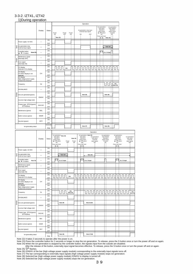
39
3-3-2. IZT41、IZT42
1)During operation
Note 22) It takes 3 seconds to operate after the power is on. Note 23) Press the controller button for 2 seconds or longer to stop the ion generation. To release, press the S button once or turn the power off and on again. Note 24) When the ion generation is stopped by the controller button, the signals input from the outside are disabled.
After the release of the button, externally input signal becomes effective. To release, press the S button once or turn the power off and on again.
Note 25) 5P flashes. Note 26) ION/HV of the bar (high voltage power supply module) corresponding to the externally input signals turns off. Note 27) The bar corresponding to externally input signals (high voltage power supply module) stops ion generation. Note 28) Selected bar (high voltage power supply module) ION/HV to display is turned off. Note 29) Selected bar (high voltage power supply module) stops the ion generation.
Display Status
Operation
Input
Power supply +24 VDC ―
Ion generation stop
External input signal―
Controller button
▲ / ▼ / S button―
Outp
ut
Maintenance signal
(Normally OFF)―
Error signal
(Normally ON)―
Maintenance (green) NDL
CH display
High voltage power supply
module disconnected
Frequency
Ions are generated (green)
ION/HV
Incorrect high voltage (red)
Hz
ION BALANCE ―
Ion generating status
Built-in sensor (green) SNSR
Key-lock (green) KEY
Dis
pla
y
CH display
Selected CH to display
CHCH display
CH which display is not
selected
Product type IZTP41(green)
IZTP42(blue)DAC/AC
PowerON
ON
OFF
ON
OFF
ON
OFF
ON
OFF
ON
OFF
ON
OFF
ON
OFF
ON
OFF
ON
OFF
ON
OFF
1Hz
Ion generation stop input.External input signal.
Press and hold
無効有効
ON
OFF
ON
OFF
PowerOFF
PowerON ON OFF ON
Ion generationstop input.Operation
button input.
▲+▼ button
ON
OFF2s or longer
Ion generationstop release.
Operation
button input.S button
ON
Note 23)
Note 23)
Note 24)
Note 22)
ON
OFF
ON
OFF
ON
OFF
1HzNote 25)
Note 27) Note 29)
Note 26) Note 28)
Generate
Stop
Display Status
Operation
Input
Power supply +24 VDC ―
Ion generation stop
External input signal―
Controller button
▲ / ▼ / S button―
Outp
ut
Maintenance signal
(Normally OFF)―
Error signal
(Normally ON)―
Maintenance (green) NDL
CH display
High voltage power supply
module disconnected
Frequency
Ions are generated (green)
ION/HV
Incorrect high voltage (red)
Hz
ION BALANCE ―
Ion generating status
Built-in sensor (green) SNSR
Key-lock (green) KEY
Dis
pla
y
CH display
Selected CH to display
CH
CH display
CH which display is not
selected
Product type IZTP41(green)
IZTP42(blue)DAC/AC
Note 23)
ON
OFF
ON
OFF
ON
OFF
ON
OFF
ON
OFF
ON
OFF
ON
OFF
ON
OFF
ON
OFF
ON
OFF
無効有効
ON
OFF
ON
OFF
Press and hold
ON
Power OFF
PowerON
1Hz
Ion generationstop input.Operation
button input.
▲+▼ button
ON
OFF2s or longer
Note 23)
Note 24)
Note 22)
ON
OFF
ON
OFF
ON
OFF
1HzNote 25)
Note 29)
Note 28)
ON
Ion generationstop input.Operation
button input.
▲+▼ button
Ion generationstop input.
External
input signal.ON
2s or longer 2s or longer
Note 23)
Note 24)
Ion generationstop release.
Operation
button input.S button
ON ON
Ion generationstop input.Operation
button input.
▲+▼ button
Ion generationstop input.
External
input signal.OFF
1HzNote 25)
Note 26,28)
Note 27,29)Generate
Stop
Press and hold Press and hold

40
2)Changing to the setting mode
Note 31) Press the controller button once or for 2 seconds or longer to change/set of the setting mode and stop/release the ion generation. To release ion generation stop, press the S button once or turn the power off and on again.
Note 32) Content of each setting mode is displayed by flashing. Refer to [4-4. Controller setting]. Note 33) Bar (high voltage power supply module) ION/HV which is selected to display is turned off. Note 34) Selected bar (high voltage power supply module) stops the ion generation.
Input
Power supply +24 VDC ―
Ion generation stop
External input signal―
Controller button
▲ / ▼ / S button―
Display Status
Changing the setting mode
Channel selection mode
↓Frequency set mode
Frequency set mode
↓Offset voltage adjustment mode
Outp
ut
Maintenance signal
(Normally OFF)―
Error signal
(Normally ON)―
ION BALANCE ―
Ions are generated (green)
ION/HV
Incorrect high voltage (red)
Frequency Hz
Product type IZTP41(green)
IZTP42(blue)DAC/AC
Maintenance (green) NDL
Ion generating status
Built-in sensor (green) SNSR
Key-lock (green) KEY
Dis
pla
y
CH display
Selected CH to display
CH
CH display
CH which display is not
selected
CH display
High voltage power supply
module disconnected
Note 31)
ON
OFF
ON
OFF
ON
OFF
ON
OFF
ON
OFF
ON
OFF
ON
OFF
ON
OFF
ON
OFF
ON
OFF
ON
OFF
ON
OFF
無効有効
ON
OFF
ON
OFF
ON
OFF
ON ON
Operation
button input.S button
Operation
button input.S button
Adjustment of theof fset voltage.
Operation
button input.
▲ or ▼ button
Setting change
Frequency selection.Operation
button input.
▲ or ▼ button
Setting changeON
Ion generationstop input.Operation
button input.
▲+▼ button
Ion generationstop release.
Operation
button input.S button
Release ON
Ion generationstop input.Operation
button input.
▲+▼ button
Ion generationstop release.
Operation
button input.S button
Release
ON
OFF
2s or longer 2s or longer
1Hz
Note 33)
Note 34)
Note 33)
Note 34)
Generate
Stop
Press and hold Press and hold
Offset voltage adjustment mode
↓Channel selection mode
Channel selection mode
↓Balance control selection mode
Changing the setting mode
Input
Power supply +24 VDC ―
Ion generation stop
External input signal―
Controller button
▲ / ▼ / S button―
Display Status
Outp
ut
Maintenance signal
(Normally OFF)―
Error signal
(Normally ON)―
ION BALANCE ―
Ions are generated (green)
ION/HV
Incorrect high voltage (red)
Frequency Hz
Product type IZTP41(green)
IZTP42(blue)DAC/AC
Maintenance (green) NDL
Ion generating status
Built-in sensor (green) SNSR
Key-lock (green) KEY
Dis
pla
y
CH display
Selected CH to display
CH
CH display
CH which display is not
selected
CH display
High voltage power supply
module disconnected
Note 31)
ON
OFF
ON
OFF
ON
OFF
ON
OFF
ON
OFF
ON
OFF
ON
OFF
ON
OFF
ON
OFF
ON
OFF
ON
OFF
ON
OFF
無効有効
ON
OFF
ON
OFF
ON
OFF
ON
Operation
button input.S button
CH selection.Operation
button input.
▲ or ▼ button
Setting change ON
Ion generationstop input.Operation
button input.
▲+▼ button
Ion generationstop release.
Operation
button input.S button
Release
ON
OFF
2s or longer
1HzNote 32)
1HzNote 32)
Operation
button input.
▲+S button
Release
Balance control selection.
Operationbutton input.
▲ or ▼ button
ON
Ion generationstop input.Operation
button input.
▲+▼ button
Ion generationstop release.
Operation
button input.S button
Release
2s or longer
ONON
2s or longer
1Hz
Note 33)
Note 34)
Note 33)
Note 34)
Generate
Stop
Press and hold Press and hold Press and hold

41
Note 30) It takes 3 seconds to operate after the power is on. Note 31) Press the controller button once or for 2 seconds or longer to change/set of the setting mode and stop/release the ion generation.
To release ion generation stop, press the S button once or turn the power off and on again. Note 32) Content of each setting mode is displayed by flashing. Refer to [4-4. Controller setting]. Note 33) Bar (high voltage power supply module) ION/HV which is selected to display is turned off. Note 34) Selected bar (high voltage power supply module) stops the ion generation. Note 35) If ON is selected for key lock setting, the setting is held even if the power is turned off and on again.
Balance control selection mode
↓Emitter contamination detection level selection mode
Emitter contamination detection level selection mode
↓Channel selection mode
Input
Power supply +24 VDC ―
Ion generation stop
External input signal―
Controller button
▲ / ▼ / S button―
Display Status
Changing the setting modeO
utp
ut
Maintenance signal
(Normally OFF)―
Error signal
(Normally ON)―
ION BALANCE ―
Ions are generated (green)
ION/HV
Incorrect high voltage (red)
Frequency Hz
Product type IZTP41(green)
IZTP42(blue)DAC/AC
Maintenance (green) NDL
Ion generating status
Built-in sensor (green) SNSR
Key-lock (green) KEY
Dis
pla
y
CH display
Selected CH to display
CH
CH display
CH which display is not
selected
CH display
High voltage power supply
module disconnected
Note 31)
ON
OFF
ON
OFF
ON
OFF
ON
OFF
ON
OFF
ON
OFF
ON
OFF
ON
OFF
ON
OFF
ON
OFF
ON
OFF
ON
OFF
無効有効
ON
OFF
ON
OFF
ON
OFF
ON
OFF
ON ON
Operation
button input.S button
Operation
button input.S button
CH selection.Operation
button input.
▲ or ▼ button
Emitter contaminationdetection level selection.
Operation button input.
▲ or ▼ button
Setting change Setting changeON
Ion generationstop input.Operation
button input.
▲+▼ button
Ion generationstop release.
Operation
button input.S button
Release ON
Ion generationstop input.Operation
button input.
▲+▼ button
Ion generationstop release.
Operation
button input.S button
Release
2s or longer 2s or longer
1HzNote 32)
1HzNote 32)
1HzNote 32)
Note 33)
Note 34)
Note 33)
Note 34)
Generate
Stop
Press and hold Press and hold
Key-lock setting mode
Input
Power supply +24 VDC ―
Ion generation stop
External input signal―
Controller button
▲ / ▼ / S button―
Display Status
Changing the setting mode
Outp
ut
Maintenance signal
(Normally OFF)―
Error signal
(Normally ON)―
ION BALANCE ―
Ions are generated (green)
ION/HV
Incorrect high voltage (red)
Frequency Hz
Product type IZTP41(green)
IZTP42(blue)DAC/AC
Maintenance (green) NDL
Ion generating status
Built-in sensor (green) SNSR
Key-lock (green) KEY
Dis
pla
y
CH display
Selected CH to display
CH
CH display
CH which display is not
selected
CH display
High voltage power supply
module disconnected
Note 31)
ON
OFF
ON
OFF
ON
OFF
ON
OFF
ON
OFF
ON
OFF
ON
OFF
ON
OFF
ON
OFF
ON
OFF
ON
OFF
ON
OFF
無効有効
ON
OFF
ON
OFF
ON
OFF
ON
OFF
PowerOFF
PowerON
3s or longer
ON
Operation
button input.S button
1Hz
Note 31)
Note 35)
Note 30)
Key-lock setting.Operation
button input.
▲ or ▼ button
Setting change ON
Operation
button input.S button
ON
Operation
button input.S button
Key-lock setting.Operation
button input.
▲ or ▼ button
Setting change ON
Operation
button input.S button
3s or longer
1Hz
Note 32)1Hz
Note 32)
Generate
Stop
Press and hold Press and hold

42
3)Error, and maintenance warning
Note 36) It takes 3 seconds to operate after the power is on. Note 37) Abnormality can be released by the ion generation stop signal.
Release the error after recovery. Note 38) Frequency with problem is displayed by flashing error code.
Refer to [4-5-2. Alarms for IZT41, IZT42]. Note 39) Frequency of the high voltage power supply module with a problem is
displayed by flashing error code. Refer to [4-5-2. Alarms for IZT41, IZT42]. High voltage power supply module without problem indicates normal status.
Note 40) Ion balance of the high voltage power supply module with problem turns off. Refer to [4-5-2. Alarms for IZT41, IZT42].
High voltage power supply module without problem indicates normal status.
Note 41) All connected high voltage power supply module ION/HV flash (green). Note 42) All ION/ HV of CH1 to 4 flash (red). Note 43) All connected high voltage power supply module ION/HV flash (red). Note 44) High voltage power supply module ION/HV with problem flashes (red). Note 45) High voltage power supply module ION/HV with problem turns on (red). Note 46) High voltage power supply module DAC/AC with problem turns off. Note 47) High voltage power supply module NDL with problem turns off. Note 48) The screen at the time of problem holds the status before the problem. Note 49) All the selected bars (high voltage power supply module) stop the ion generation. Note 50) Bar with a problem (high voltage power supply module) stops the ion generation.
Controller button
▲ / ▼ / S button
Incorrect high voltage
Error code:E3
Display Status
CPU failure
(controller)
Error code:E0
Power supply failure
Error code:E1
CPU failure
(High voltage power supply
module)
Error code:E2
―
Input
Power supply +24 VDC ―
Ion generation stop
External input signal―
ION BALANCE ―
Ions are generated (green)
Outp
ut
Maintenance signal
(Normally OFF)―
Error signal
(Normally ON)―
Ion generating status
Key-lock (green) KEY
Dis
pla
y
CH display
Selected CH to display
CH
CH display
CH which display is not
selected
CH display
High voltage power supply
module disconnected
Frequency Hz
Communication error
Error code:E4
Fan motor failure
Error code:E5
Built-in sensor (green) SNSR
Product type IZTP41(green)
IZTP42(blue)DAC/AC
Maintenance (green) NDL
ION/HV
Incorrect high voltage (red)
ON
OFF
ON
OFF
ON
OFF
ON
OFF
ON
OFF
ON
OFF
ON
OFF
ON
OFF
ON
OFF
ON
OFF
ON
OFF
ON
OFF
Error Error Error
Note 48) Note 48) Note48)
Error
Note 48)
無効有効
ON
OFF
ON
OFF
PowerOFF
PowerON
PowerOFF
PowerON
PowerOFF
PowerON
ON
OFF
Note 48) Note 48) Note 48)
1HzNote 38)
1HzNote 38)
1HzNote 39)
1HzNote 39)
1HzNote 42)
1HzNote 43)
1HzNote 44) Note 45)
Note 36) Note 36) Note 36)
ON
OFF
1Hz 1Hz 1Hz 1Hz
Note 37)
Note 40) Note 40)
Note 49) Note 49) Note50) Note 50)
Error
Note 48)
PowerOFF
PowerON
Error
PowerOFF
PowerON
Note 48) Note 48)
Note 48)
1HzNote 39)
1HzNote 39)
1HzNote 44)
1HzNote 44)
Note 37)
Note 36) Note 36)
1Hz1Hz
Note 37)
Note 40) Note 40)
Note 50) Note 50)
Note 47) Note 47) Note 47) Note 47) Note47)
Generate
Stop
Controller button
▲ / ▼ / S button
High voltage power supply
module not connected
Error code:--
Inconsistent module
Error code:E6
Duplication of CH
Error code:E7
Display Status
―
Input
Power supply +24 VDC ―
Ion generation stop
External input signal―
Ions are generated (green)
ION/HV
Outp
ut
Maintenance signal
(Normally OFF)―
Error signal
(Normally ON)―
Ion generating status
Key-lock (green) KEY
Dis
pla
y
CH display
Selected CH to display
CH
CH display
CH which display is not
selected
CH display
High voltage power supply
module disconnected
Frequency Hz
Output signal over current
Error code:E8 (Error signal)
Error code:E9(Maintenance signal)
Maintenance warning
Built-in sensor (green) SNSR
Product type IZTP41(green)
IZTP42(blue)DAC/AC
Maintenance (green) NDL
Incorrect high voltage (red)
ION BALANCE ―
ON
OFF
ON
OFF
ON
OFF
ON
OFF
ON
OFF
ON
OFF
ON
OFF
ON
OFF
ON
OFF
ON
OFF
ON
OFF
ON
OFF
無効有効
ON
OFF
ON
OFF
ON
OFF
ON
OFF
Error
Note 48)
PowerOFF
PowerON
Error
Note 48)
Note 48) Note 48)
1HzNote 39)
1HzNote 39)
1HzNote 44)
1HzNote 44)
Note 36)
1Hz
Note 40) Note 40)
Note 46) Note 46)
Note 50) Note 50)
Warning
Note 48)
PowerOFF
PowerON
Error
Note 48)
Error
PowerOFF
PowerON
Note 48) Note 48)
1HzNote 38)
1HzNote 38)
1HzNote 41)
Note 37)
Note 36) Note 36)
Note 48)
1Hz 1Hz
Note 48)Note 47) Note 47)
Generate
Stop

43
4. Function 4-1. Name of Parts 4-1-1. Controller
1)IZTC40
Note51) Refer to [4-4. Controller setting] or [4-5-1. Alarm for IZT40] for details of frequency.
9
10
1
6 5 7
2
3
4
8
Table11. Name of parts
No. NamePanel
indicationType Description
1 CH display CHLED
(Green)
High voltage power supply module connected to the controller is ON (green).
Flashes (green) when selecting frequency or adjusting the offset voltage.
2 Frequency display HzLED
(Green)
Green LED is ON during operation.
Green LED flashes during frequency selection, adjustment of the offset voltage and abnormality exists.
Note 51)
3Ion emission/
high voltage error displayION/HV
LED
(Green /
Red)
Green LED is ON during static neutralization.
Red LED is ON when high voltage abnormality exists.
LED flashes (red) when CPU abnormality (controller/ high voltage power supply module),
power supply abnormality, communication error, cooling fan motor failure, module inconsistency,
or CH duplication exists.
Turned off when the high voltage power supply module is not connected.
4 Key-lock display KEYLED
(Green)
Key lock ON : ON (green)
Key lock OFF : OFF
5 ▼ button - Press button Decrease the set value.
6 S button - Press button Change the mode and set a set value.
7 ▲ button - Press button Increase the set value.
8 Reset button - Press button Return the setting values of each mode to the default condition.
9 Power supply connector - Connector Equipped with ionizer power supply and grounding.
10High voltage power supply
module connector-
D-sub
connector
(socket)
Connect high voltage power supply module or separate cable.

44
2)IZTC41
Note 52) Refer to [4-4. Controller setting] or [4-5-2. Alarms for IZT41, IZT42] for details of frequency.
13
14
1
10 9
2
4
7 8
3
5 6
11
12
Table12. Name of parts
No. NamePanel
indicationType Description
1 CH display CH□LED
(Green)
LED of high voltage power supply module connected to the controller is ON (green),
LED flashes (green) during frequency selection, offset voltage adjustment,
balance control selection, emitter contamination detection level selection,
Turned off when the high voltage power supply module is not connected.
2 Frequency display HzLED
(Green)
ON during operation,LED flashes (green) during frequency selection,
offset voltage adjustment,balance control selection,
emitter contamination detection level selection,
key lock setting and each abnormality. Note 52)
3 Ion balance display ION BALANCELED
(Green/ Orange)
LED (green) is ON during operation or output signal over current.
LED (green) flashes during offset voltage adjustment.
LED is OFF flashes (red) when CPU abnormality (controller/ high voltage power supply
module),
power supply abnormality, communication error, cooling fan motor failure,
module inconsistency, or CH duplication exists.
LED (orange) flashes when ion balance is maximum or minimum during offset
adjustment.
Turned off when the high voltage power supply module is not connected
4Ion emission/
high voltage error displayION/HV
LED
(Green / Red)
Green LED is ON during static neutralization.
Red LED is ON when high voltage abnormality exists.
LED flashes (red) when CPU abnormality (controller/ high voltage power supply module),
power supply abnormality, communication error, cooling fan motor failure,
module inconsistency, or CH duplication exists.
Turned odd when the high voltage power supply module is not connected
5 Indication of connected mode DAC/ACLED
(Green /Blue)
LED is ON (green) when the high voltage power supply module IZTP41 is connected.
LED is ON (blue) when the high voltage power supply module IZTP42 is connected.
OFF when CPU abnormality (controller) or CH duplication exists,
or high voltage power supply module is not connected.
6 Maintenance display NDLLED
(Green)
LED (green) is ON when emitter contamination is detected.
LED (green) flashes when the emitter contamination detection level is set.
Turned off when the high voltage power supply module is not connected
7 Key-lock display KEYLED
(Green)
Key lock ON : ON (green)
Key lock OFF : OFF
Turned off when the high voltage power supply module is not connected.
8 Sensor LED SNSRLED
(Green)
Auto balance function ON : ON (green)
Auto balance function OFF : OFF
OFF when CPU abnormality (controller) exists or high voltage power supply module
is not connected.
9 ▼ button - Press button Decrease the set value.
10 S button - Press button Change the mode and set a set value.
11 ▲ button - Press button Increase the set value.
12 Reset button - Press button Return the setting values of each mode to the default condition.
13 Power supply connector - Connector Equipped with ionizer power supply and grounding.
14High voltage power supply
module connector-
D-sub
connector
(socket)
Connect high voltage power supply module or separate cable.

45
4-1-2. High voltage power supply module
1)IZTP40、IZTP41
2)IZTP42
1
2
4
3
4 3
2
1
Table13. Name of parts
No. NamePanel
indicationType Description
1 CH number set switch CH Rotary switch High voltage power supply module CH number setting.
2 High voltage cable connector - Connector Connect with the high voltage cable of the bar IZTB40
3High voltage power supply
module connector-
D-sub connector
(socket)Connect high voltage power supply module or separate cable.
4Controller/ high voltage
power supply module connector-
D-sub connector
(plug)Connect the controller, high voltage power supply module or separate cable.
Table14. Name of parts
No. NamePanel
indicationType Description
1 CH number set switch CH Rotary switch High voltage power supply module CH number setting
2 High voltage cable connector - Connector Connect with the high voltage cable of the bar IZTB42
3High voltage power supply
module connector-
D-sub connector
(socket)Connect high voltage power supply module or separate cable.
4Controller/ high voltage
power supply module connector-
D-sub connector
(plug)Connect the controller, high voltage power supply module or separate cable.

46
4-2. Operation modes · The product has 3 operation modes. AC mode, dual AC mode and DC mode.
· The operation modes available varies depending on the model.
Ionizer operation modes
AC mode IZT40, IZT41
DC mode (Either positive ions or negative ions are continuously discharged during operation)
IZT42 Dual AC mode
4-2-1. Operation modes of IZT40 and IZT41
1) AC mode
· Ions of different polarity are generated alternately according to the frequency set by the frequency set mode.
· If the offset voltage (ion balance) is displaced by the installation environment of the ionizer, adjust the offset voltage.
· Refer to [4-4-3. Frequency set mode] for frequency setting and [4-4-4. Offset voltage adjustment mode] for the adjustment of the offset voltage (ion balance).
2) DC mode
· Positive ions are generated when "dp" is set for the frequency mode. Negative ions are generated by
setting "dn".
· Refer to 4-4-3. Frequency set mode for further details.
4-2-2. Operation modes of IZT42
· In dual AC mode, ions of different polarity are generated alternately from electrodes positioned next to each other, and either "+" or "-" ions are generated according to the frequency set for the frequency set mode.
· Refer to 4-4-3. Frequency set mode for further details.
· In the dual AC mode, it is possible to reduce the potential amplitude applied to the workpiece compared with in the AC mode. (Refer to "6. Performance" for details)
Ion generation image in AC mode
Ion generation image in AC mode

47
4-3. High voltage power supply module CH number setting · When multiple high voltage power supply modules are connected to one controller, the CH number must be
set for each high voltage power supply module to identify the information and set time.
· The CH number can be assigned from 1 to 4. (Up to 4 modules can be connected). Set the CH number using the rotary switch on the high voltage power supply module.
· The CH number set for the high voltage power supply module corresponds with the CH number displayed on the controller.
· When multiple high voltage power supply modules are used (max 4 pcs.), the CH number must not be
duplicated. Duplication of the CH number will generate an error (error code: E7).
Controller
CH number
High voltage power supply module
CH number set switch (Fig. shows the setting to 1.)

48
4-4. Controller setting 4-4-1. Operation overview 1) Setting IZT40
(Default condition) Frequency setting : 30Hz Key lock : OFF
[Channel selection mode] Select the CH number for setting and display. When multiple bars (high voltage power supply modules) are
connected, switch the CH for setting and display. Refer to 4-4-2. Channel selection mode for details. Note 53)
[Frequency set mode]
Set the ion generation frequency of the bar selected by "Channel selection mode”. Refer to 4-4-3. Frequency set mode for details.
Note 53)
[Key-lock setting mode]
Perform a key-lock setting. Refer to 4-4-7.Key-lock set mode for details.
[Offset voltage adjustment mode]
Adjust the offset voltage of the bar selected by ”CH selection mode". Refer to "4-4-4. Adjustment of Offset Voltage" for details.
Note 53)
[Channel selection mode]
Press S button once Press S button for 3 sec. or longer
Press S button once
Press S button once Press S button once
Immediately after power is supplied
Note 53) In Channel selection mode, frequency set mode, or offset voltage adjustment mode, the selected bar (high voltage power supply module) moves on to the ion generation stop mode by pressing ▼ and ▲ button simultaneously for 2 s or longer and stops the ion generation. (Operation is not possible while the key lock is ON). To release, press the S button once or turn the power off and on again. Refer to [ 4-4-8. ion generation stop mode] for further details

49
2) Setting IZT41 and IZT42
(Default condition) Frequency setting : 30Hz Key lock : OFF Built-in sensor : ON Emitter contamination : MIDDLE
Note 54) In Channel selection mode, frequency set mode, offset voltage adjustment mode, balance control selection mode or emitter contamination detection level selection mode, the selected bar (high voltage power supply module) moves on to the ion generation stop mode by pressing ▼ and ▲ button simultaneously for 2 s or longer and stops the ion generation. (Operation is not possible while the key lock is ON or externally input signal is ON) To release, press the S button once or turn the power off and on again. Refer to[ 4-4-8. ion generation stop mode] for further details.
[Channel selection mode] Select the CH number for setting and display. When multiple high voltage power supply modules are connected, switch the CH for setting and display. Refer to 4-4-2. Channel selection mode for details.
Note 54)
[Frequency set mode] Set the ion generation frequency of the bar selected by "Channel selection mode”. Refer to 4-4-3. Frequency set mode for details.
Note 54)
[ Key-lock setting mode]
Perform a key-lock setting. Refer to 4-4-7. Key-lock set mode for details.
[ Balance control selection mode ]
Select ON/ OFF of the balance control by the sensor built in the high voltage power supply module selected in "Channel selection mode" Refer to 4-4-5. Balance control selection mode for details. Note 54)
[Offset voltage adjustment mode]
Adjust the offset voltage of the bar selected by ”CH selection mode". Refer to "4-4-4. Adjustment of Offset Voltage" for details.
Note 54)
[ Emitter contamination detection level selection mode] Set the contamination detection level of the high voltage power supply module emitter selected by "Channel selection mode". Refer to 4-4-6. Emitter contamination detection level selection mode for details. Note 54)
[Channel selection mode]
Press S button once
Press S button once
Press S button once
Press S button once
Press S button for 3 sec. or longer
Press the △ button and S button at the same time for
2 seconds or longer.
Power is supplied.
Press S button once
Press S button once

50
4-4-2. Channel selection mode Applicable models: IZT40, IZT41, IZT42
· When power is supplied to the controller, the CH LED (green) of the connected bar (high voltage power supply module) turns on or flashes. A flashing CH LED indicates the selected CH. The LED for frequency, ION BALANCE and SNSR display the information of the selected CH.
· The LED for ION/HV, DAC/AC and NDL display all the information of the connected bar (high voltage power supply module). (For IZT40, ION BALANCE, SNSR, DAC/AC, and NDL are not displayed)
· The controller CH1 to CH4 LED’s correspond to CH no. 1 to 4 set for the high voltage power supply modules.
· The maximum number of bars (high voltage power supply modules) for one controller is 4 pcs.
· Duplication of CH setting will be recognized as an error.
[ Selection of the channel ]
· The selected CH will flash.
· Press the ▼ or ▲ button while the CH LED flashes to select the bar (high voltage power supply module) to display or set.
· When the number of bars is zero, the CH LED does not change even by pressing the ▼ or ▲ button.
[Change to the next mode]
· To change to the next mode and store the selected CH setting press the S button once, the ▲ and S button simultaneously for 2 s or longer, or the S button for 3 s or longer. (for the IZTC40, the mode does not change by pressing ▲ button and S button for 2 s or longer.)
· The selected bar (high voltage power supply module) moves on to the ion generation stop mode by pressing ▼ and ▲ button simultaneously for 2 s or longer and stops the ion generation. To release, press the S button once or turn the power off and on again. Refer to[ 4-4-8. Ion generation stop mode].
Example shows CH1 is selected.
Change the CH setting for multiple modules. (Default CH switch setting is "1".)
CH set switch High voltage power supply module
Flash (green)
Display example of
IZTC40
Display example of IZTC41

51
4-4-3. Frequency set mode Applicable models: IZT40, IZT41, IZT42
· Set the ion generation frequency of the bar (high voltage power supply module) selected by "Channel selection mode”.
[Ion generating frequency setting]
· Select the CH in the selection mode and press the S button once. The frequency will flash and the setting of the ion generation frequency of the selected bar becomes possible.
· The Ion generation frequency is set by pressing the ▼ or ▲ button.
· The Frequency display is different depending on the model. Refer to the display of frequency example below.
[Change to the next mode]
· Press the S button once to change to the next mode and store the frequency setting.
· When the power is supplied the saved setting will be displayed.
· The selected bar (high voltage power supply module) moves on to the ion generation stop mode by pressing ▼ and ▲ button simultaneously for 2 s or longer and stops the ion generation. To release, press the S button once or turn the power off and on again. Refer to[ 4-4-8. Ion generation stop mode].
※Caution
If the mode is changed to ion generation stop mode during the frequency setting or the ion generation is stopped by turning off the power supply, the setting during change is not stored. Change the setting again.
Display of frequency
●IZT40/IZT41
●IZT42
1Hz 3Hz 5Hz 8Hz 10Hz 15Hz 20Hz 30Hz DC+ DC-
0.1Hz 0.5Hz 1Hz 3Hz 5Hz 8Hz 10Hz 15Hz 20Hz 30Hz
Default frequency setting is “30 Hz“. Set the optimum frequency depending on the operating environment and installed distance.
Example of frequency setting mode for CH1. Frequency 30 Hz.
Flash (green)
Display example of IZTC40
Flash (green)
Display example of IZTC41

52
4-4-4. Offset voltage adjustment mode Applicable models: IZT40, IZT41, IZT42
· Offset voltage is adjusted before shipment. However, readjustment of the offset voltage is possible where it is required depending on the installation environment. (The same applies when the ionizer is moved and installed in a different location.)
· When there are ionizers installed near the ionizer whose offset voltage is to be adjusted, stop the ionizers which are not adjusted for the offset voltage before starting adjustment.
1) Adjustment of IZT40 offset voltage
· Select the CH to be set in CH selection mode and press the S button twice.
The frequency display "Ib" will flash and the adjustment of the offset voltage is now possible.
· IZT40 does not have a built in sensor. Adjust the offset voltage by monitoring the ion generated with a charge plate monitor etc.
· Press ▼ or ▲ button for adjustment. Press the ▲ button once to increase + ion, press and hold to
continuously increase. Press the ▼ button once to increase - ion, press and hold to
continuously increase.
[Change to the next mode]
· Press the S button once to change to the next mode and store the offset voltage adjustment setting.
· When power is supplied, the saved setting will be displayed.
2) Adjustment of IZT41 and IZT42 offset voltage
· Select the CH to be set in CH selection mode and press the S button twice.
The frequency display "Ib" and ion balance display will flash, and the adjustment of the offset voltage is now possible.
· The Ion balance display shows the ion balance detected by the built-in sensor. Adjust so that the flashing LED becomes central.
· The LED turns on when it approaches the centre, and flashes as it moves away from it. At the positive ion adjustment limit, the LED at the end of the positive side (right end of the display) flashes (orange). At the negative ion adjustment limit, the LED at the end of the negative side (left end of the display) flashes (orange).
· For highly precise offset voltage adjustment, adjust the ions generated by the ionizer by monitoring with a charge plate monitor.
· Press ▼ or ▲ button for adjustment. Press the ▲ button once to increase + ion, press and hold to
continuously increase. Press the ▼ button once to increase - ion, press and hold to
continuously increase.
[Change to the next mode]
· Press the S button once to change to the next mode and store the offset voltage adjustment setting.
· When power is supplied, the saved setting will be displayed.
Flash (green)
Display example of
IZTC40 Example shows the offset voltage
adjustment mode of CH1.
Example shows the offset voltage adjustment mode of CH1.
Display example of
IZTC41
Flash (green)

53
· The selected bar (high voltage power supply module) moves on to the ion generation stop mode by pressing ▼ and ▲ button simultaneously for 2 s or longer and stops ion generation. To release, press the S button once or turn the power off and on again. Refer to [ 4-4-8. ion generation stop mode].
※Caution
If the mode is changed to ion generation stop mode during offset voltage adjustment or the power supply is turned off, the change to the setting will not be stored. Change the setting again.
4-4-5. Balance control selection mode
Applicable models: IZT41, IZT42
· IZT41 and IZT42 have a built in sensor to balance the ions generated.
· Balance control selection mode turns the balance control by the built-in sensor on and off. (the IZT40 does not have this function).
[Selection of balance control]
· Select the CH to be set in CH selection mode and press the S button and ▲ button simultaneously for 2 s or longer. The
frequency display indicates "5n" flashing, and the switching of ON and OFF of balance control is now possible.
· The Sensor display (SNSR) LED (green) alternates ON and OFF each time the ▼ or ▲ button is pressed.
Balance control ON: Sensor display (SNSR) LED is ON Balance control OFF: Sensor display (SNSR) LED is OFF
[Change to the next mode]
· Press the S button once to change to the next mode and store the balance control selection setting.
· When power is supplied the saved setting will be displayed.
· The selected bar (high voltage power supply module) moves on to the ion generation stop mode by pressing ▼ and ▲ button simultaneously for 2 s or longer and stops ion generation. To release, press the S button once or turn the power off and on again. Refer to [ 4-4-8. ion generation stop mode].
※Caution
If the mode is changed to ion generation stop mode during balance control selection or if the power supply is turned off, the change to the setting will not be stored. Change the setting again.
Default balance control setting is ON.
- ion increases
+ ion increases
Example shows the ON status of CH1 balance control.
Flash (green)
ON (green)
or OFF
Display example of IZTC41

54
4-4-6. Emitter contamination detection level selection mode Applicable models: IZT41, IZT42
· If the ionizer is used for an extended period of time, contamination such as dust will stick to the emitters, reducing the static neutralization performance.
· It is recommended to clean the emitters when the maintenance alarm is generated.
· The cleaning frequency varies depending on the environment where the ionizer is installed.
· This product has a function which monitors the emitter contamination all the time. When the emitter contamination is detected, it is indicated by the maintenance signal and LED.
· In Emitter contamination detection level selection mode, the detection level of the emitter contamination can be set. (the IZT40 does not have this function.)
[Emitter contamination detection level selection method]
· In CH selection mode, press the S and ▲ buttons simultaneously for 2 s or longer to move to balance control selection mode.
· By pressing the S button once, “Xi” or “Mi” or “Lo” or “oF” will flash in the frequency display. The detection level of the emitter contamination can now be selected.
· It can be set by pressing the ▼ or ▲ button.
Lo (Low)・・・・・Static neutralization time is slower than the initial state
Mi (Middle)・・・Before the static neutralization time becomes slow
Xi (High)・・・・・No influence to the static neutralization time
oF(OFF)・・・・・・Emitter contamination detection is OFF
[Change to the next mode]
· Press the S button once to change to the next mode and store the emitter contamination detection level selection setting.
· When power is supplied, the saved setting will be displayed.
· The selected bar (high voltage power supply module) moves on to the ion generation stop mode by pressing ▼ and ▲ button simultaneously for 2 s or longer and stops ion generation. To release, press the S button once or turn the power off and on again. Refer to [ 4-4-8. ion generation stop mode].
※Caution
If the mode is changed to ion generation stop mode during emitter contamination detection level selection or the power supply is turned off, the change to the setting will not be stored. Change the setting again.
Default emitter contamination detection level setting is "Middle".
Change the setting to change the contamination detection level.
Example shows the emitter contamination detection
level of CH1.
Flash (green)
Display example of IZTC41
Low Middle High
OFF

55
4-4-7. Key-lock setting mode Applicable models: IZT40, IZT41, IZT42
· This product has a key lock function which disables any button operation.
【Key-lock setting】
· Press the S button for 3 s or longer in CH selection
mode, "Lc" or "VL" will flash in the frequency display and the ON/OFF setting of the key lock function is now possible.
· The key lock condition is indicated by "Lc" in the frequency display and by the key lock LED (green).
Key lock function ON :
Frequency display : “Lc” flashes / KEY LED is ON Key lock function OFF :
Frequency display : “VL” flashes / KEY LED is OFF
[Change to the next mode]
· Press the S button once to change to CH selection mode and store the key lock setting.
· When power is supplied, the saved setting will be displayed.
·
Default key lock setting is OFF.
Example shows Key lock ON.
Display example of IZTC40
Flash (green)
ON (green)
or OFF
Flash (green)
ON (green)
or OFF
Display example of IZTC41
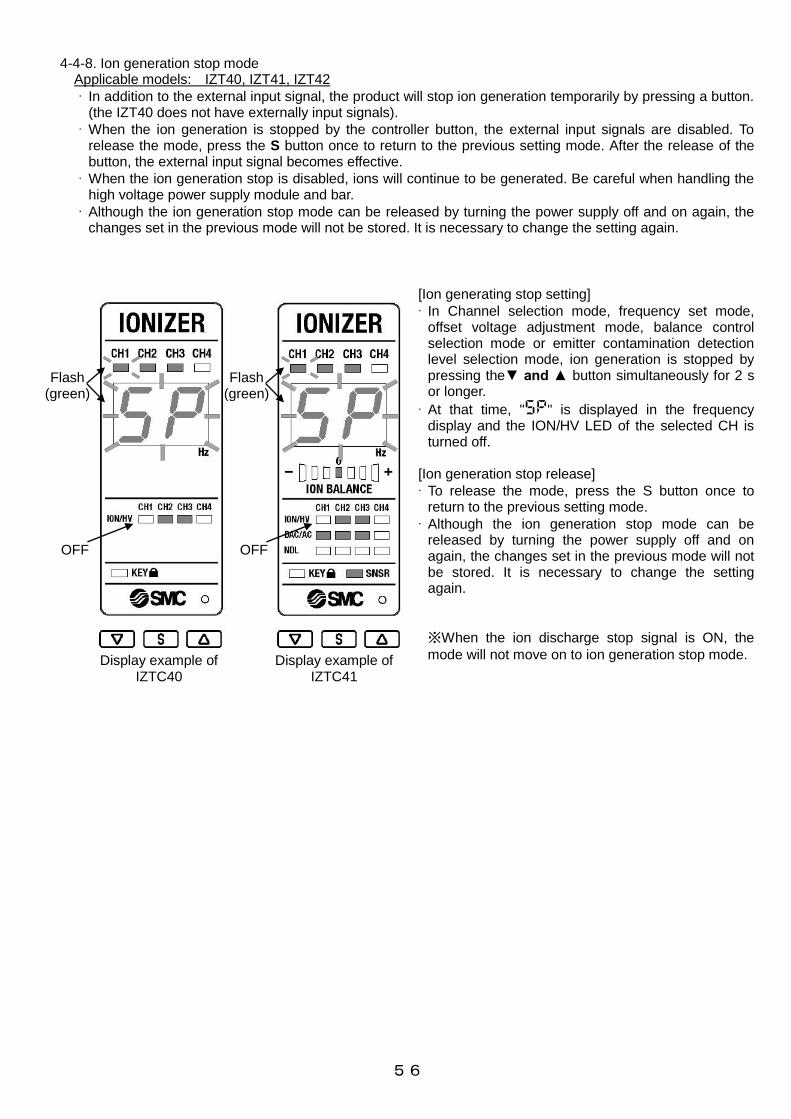
56
4-4-8. Ion generation stop mode Applicable models: IZT40, IZT41, IZT42
· In addition to the external input signal, the product will stop ion generation temporarily by pressing a button. (the IZT40 does not have externally input signals).
· When the ion generation is stopped by the controller button, the external input signals are disabled. To release the mode, press the S button once to return to the previous setting mode. After the release of the button, the external input signal becomes effective.
· When the ion generation stop is disabled, ions will continue to be generated. Be careful when handling the high voltage power supply module and bar.
· Although the ion generation stop mode can be released by turning the power supply off and on again, the changes set in the previous mode will not be stored. It is necessary to change the setting again.
[Ion generating stop setting]
· In Channel selection mode, frequency set mode, offset voltage adjustment mode, balance control selection mode or emitter contamination detection level selection mode, ion generation is stopped by pressing the▼ and ▲ button simultaneously for 2 s or longer.
· At that time, "5p" is displayed in the frequency display and the ION/HV LED of the selected CH is turned off.
[Ion generation stop release]
· To release the mode, press the S button once to return to the previous setting mode.
· Although the ion generation stop mode can be released by turning the power supply off and on again, the changes set in the previous mode will not be stored. It is necessary to change the setting again.
※When the ion discharge stop signal is ON, the
mode will not move on to ion generation stop mode.
Flash (green)
OFF
Display example of IZTC40
Display example of IZTC41
Flash (green)
OFF

57
4-5. Alarm function · When a problem occurs, an output signal or LED notification is generated.
· Depending on the content of abnormality, the ionizer either continues or stops operation. IZT40 does not have output functions.
4-5-1. Alarms for IZT40
Note55) All CH LEDs in the CH table are ON (green). Note56) LED for all connected high voltage power supply modules CH are ON (green). Note57) LED for CHs selected to display flashing (green). Note58) All ION/ HV LEDs for CH1 to 4 flash (red). Note59) LED for all connected high voltage power supply modules ION/HV flash (red). Note60) LED for high voltage power supply module ION/HV with problem flashes (red). Note61) LED for high voltage power supply module ION/HV with problem turns on (red). Note62) The screen at the time of the problem holds the status before the problem.
Table15. Alarm function
CH Frequency ION/HV KEY
CPU failure
(controller)Stop
Green
(ON)Note55)
Green
(flash)
error code
E0
Red
(flash)Note58)
OFF
or Note62)
green
(ON)
・When CPU operates abnormally due
to noise etc.
・When the CH is switched during
operation.
・Turn the power off and
on again
Power supply failure Stop
Green
(ON)Note56)
Green
(flash)
Error code
E1
Red
(flash)Note59)
OFF
or Note62)
green
(ON)
・When the connected power supply
voltage is outside of the specification.
・To be reset
automatically.
CPU failure
(High voltage power
supply module)
Stop
Green
(flash)Note57)
Green
(flash)
error code
E2
Red
(flash)Note60)
OFF
or Note62)
green
(ON)
・When CPU operates abnormally due
to noise etc.
・High voltage cable to be connected
to the high voltage power supply
module is not connected.
・Turn the power off and
on again
Incorrect high voltage Stop
Green
(flash)Note57)
Green
(flash)
error code
E3
Red
(ON)Note61)
OFF
or Note62)
green
(ON)
・When abnormal high voltage is
discharged.
・Turn the power off and
on again
Communication error Stop
Green
(flash)Note57)
Green
(flash)
error code
E4
Red
(flash)Note60)
OFF
or Note62)
green
(ON)
・When communication failure occurs
due to noise, etc.
・Turn the power off and
on again
Fan motor failure Stop
Green
(flash)Note57)
Green
(flash)
error code
E5
Red
(flash)Note60)
OFF
or Note62)
green
(ON)
・When ionizer does not operate
properly due to foreign matter caught
in the fan motor.
・Turn the power off and
on again
Inconsistent module Stop
Green
(flash)Note57)
Green
(flash)
error code
E6
Red
(flash)Note60)
OFF
or Note62)
green
(ON)
・High voltage power supply module
which is not correct combination was
connected to the controller.
・Turn the power off and
on again
Duplication of CH Stop
Green
(flash)Note57)
Green
(flash)
Error code
E7
Red
(flash)Note60)
OFF
or Note62)
green
(ON)
・Duplication of the CH setting of the
high voltage power supply module
connected to the controller exists.
・To be reset
automatically.
High voltage power
supply module not
connected
Stop OFF
Green
(flash)
Error code
--
OFF OFF
・High voltage power supply module to
be connected to the controller is not
connected.
・Turn the power off and
on again
Alarm name
Ionizer
operation after
generating
alarm
LED
DescriptionHow to release error after
recovery

58
4-5-2. Alarms for IZT41 and IZT42
Note63) All CH LEDs in the CH table are ON (green). Note64) LED for all connected high voltage power supply modules CH flash (green). Note65) LED for CHs selected to display flashing (green). Note66) Displays the frequency setting status of the selected CH. Note67) Ion balance of the high voltage power supply module with problem turns off. Note68) All ION/ HV LEDs for CH1 to 4 flash (red). Note69) LED for all connected high voltage power supply modules ION/HV flash (green). Note70) LED for high voltage power supply module ION/HV with problem flashes (red). Note71) LED for high voltage power supply module ION/HV with problem turns on (red). Note72) LED for all connected high voltage power supply modules ION/HV flash (green). Note73) Displays the type of connected high voltage power supply module.
IZT41: DAC/AC LED (green) is ON IZT42: DAC/AC LED (blue) is ON
Note74) LED for high voltage power supply module DAC/AC with problem turns off. Note75) LED for high voltage power supply module NDL with problem turns off. Note76) The screen at the time of the problem holds the status before the problem.
Table16. Alarm function
CH FrequencyION
BALANCEION/HV DAC/AC NDL SNSR KEY
CPU failure
(controller)
Abnormal
signal OFF
(B contact)
Stop
Green
(ON)Note63)
Green
(flash)
error code
E0
OFF
Red
(flash)Note68)
OFF OFF OFF
OFF
or Note76)
Green
(ON)
・When CPU operates abnormally
due to noise etc.
・When the CH is switched during
operation.
・Turn the power off and
on again.
Power supply failure
Abnormal
signal OFF
(B contact)
Stop
Green
(ON)Note64)
Green
(flash)
error code
E1
OFF
Red
(flash)Note69)
Green
(ON)
or Note73)
Blue
(ON)
OFF
OFF
or Note76)
Green
(ON)
OFF
or Note76)
Green
(ON)
・When the connected power supply
voltage is outside of the
specification.
・To be reset
automatically.
CPU failure
(High voltage power
supply module)
Abnormal
signal OFF
(B contact)
Stop
Green
(flash)Note65)
Green
(flash)
error code
E2
OFFNote67)
Red
(flash)Note70)
Green
(ON)
or Note73)
Blue
(ON)
OFFNote75)
OFF
or Note76)
Green
(ON)
OFF
or Note76)
Green
(ON)
・When CPU operates abnormally
due to noise etc.
・High voltage cable to be connected
to the high voltage power supply
module is not connected.
・Turn the power off and
on again.
Incorrect high voltage
Abnormal
signal OFF
(B contact)
Stop
Green
(flash)Note65)
Green
(flash)
error code
E3
OFFNote67)
Red
(ON)Note71)
Green
(ON)
or Note73)
Blue
(ON)
OFFNote75)
OFF
or Note76)
Green
(ON)
OFF
or Note76)
Green
(ON)
・When abnormal high voltage is
discharged.
・Ion generation stop
signal OFF and ON again.
・Turn the power off and
on again.
Communication error
Abnormal
signal OFF
(B contact)
Stop
Green
(flash)Note 65)
Green
(flash)
error code
E4
OFFNote67)
Red
(flash)Note70)
Green
(ON)
or Note73)
Blue
(ON)
OFFNote75)
OFF
or Note76)
Green
(ON)
OFF
or Note76)
Green
(ON)
・When communication failure
occurs due to noise, etc.
・Ion generation stop
signal OFF and ON again.
・Turn the power off and
on again.
Fan motor failure
Abnormal
signal OFF
(B contact)
Stop
Green
(flash)Note65)
Green
(flash)
error code
E5
OFFNote67)
Red
(flash)Note70)
Green
(ON)
or Note73)
Blue
(ON)
OFFNote75)
OFF
or Note76)
Green
(ON)
OFF
or Note76)
Green
(ON)
・When ionizer does not operate
properly due to foreign matter caught
in the fan motor.
・Ion generation stop
signal OFF and ON again.
・Turn the power off and
on again.
Inconsistent module
Abnormal
signal OFF
(B contact)
Stop
Green
(flash)Note 65)
Green
(flash)
error code
E6
OFFNote67)
Red
(flash)Note70)
OFFNote74)
OFFNote75)
OFF
or Note76)
Green
(ON)
OFF
or Note76)
Green
(ON)
・High voltage power supply module
which is not correct combination
was connected to the controller.
・Turn the power off and
on again.
Duplication of CH
Abnormal
signal OFF
(B contact)
Stop
Green
(flash)Note65)
Green
(flash)
error code
E7
OFFNote67
Red
(flash)Note70)
OFFNote74)
OFFNote75)
OFF
or Note76)
Green
(ON)
OFF
or Note76)
Green
(ON)
・Duplication of the CH setting of the
high voltage power supply module
connected to the controller exists.
・To be reset
automatically.
Output signal over
current
Maintenance
signal OFF
(A contact)
Abnormality
signal OFF
(B contact)
Continue
Green
(flash)Note65)
Green
(flash)
error code
E8
E9
Green
(ON)
Green
(flash)Note72)
Green
(ON)
or Note73)
Blue
(ON)
OFF
or Note76)
Green
(ON)
OFF
or Note76)
Green
(ON)
OFF
or Note76)
Green
(ON)
・When over current is applied to the
output circuit and protective circuit is
activated.
・To be reset
automatically.
Maintenance warning
Maintenance
signal ON
(A contact)
Continue
Green
(flash)Note65)
Green
(ON)
frequencyNote66)
Green
(ON)
Green
(ON)
Green (ON)
or Note73)
Blue
(ON)
Green
(ON)
OFF
or Note76)
Green
(ON)
OFF
or Note76)
Green
(ON)
・When static neutralization
performance is reduced due to
contamination, wearing or breakage
of emitters.
・Ion generation stop
signal OFF and ON again.
・Turn the power off and
on again.
High voltage power
supply module
not connected
Abnormal
signal OFF
(B contact)
Stop OFF
Green
(flash)
Error code
--
OFF OFF OFF OFF OFF
OFF
or Note76)
Green
(ON)
・High voltage power supply module
to be connected to the controller is
not connected.
・Turn the power off and
on again.
Alarm name Output signal
Ionizer
operation after
generating
alarm
LED
DescriptionHow to release error after
recovery

59
4-5-3. Details of the alarms 1) Controller CPU problem (applicable product model: IZT40, IZT41, IZT42)
· If the controller CPU operation is abnormal due to electrical noise, or when the CH is switched during operation, the abnormal signal is OFF (ON when normal. IZTC40 does not have an output signal), and all
CH LEDs (green) are ON and all ION/HV LEDs are flashing (red) and the error code "E0" is displayed in frequency display flashing red.
· When failure occurs, the ion generation will be stopped.
· To prevent noise, perform the following actions and take countermeasures.
Ⅰ. If the source of noise is nearby, move the ionizer away from the source.
Ⅱ. Route the power line and ionizer cables separately.
Ⅲ. If noise may enter the product from the power supply, install a noise filter to the ionizer power supply.
· To resolve the error, supply power again after fixing the cause of the error. 2) Power supply failure (applicable models: IZT40, IZT41, IZT42)
· When the power supply connected to the ionizer is not within the specified range of 24 V +/-10%, the abnormal signal is OFF (ON when normal. IZTC does not have an output signal), and all CH LEDs connected to the bar (high voltage power supply module) are ON (green), ION/HV LEDs of connected CH
are flashing (red) and the error code "E1" is displayed flashing in the frequency display.
· When the failure occurs, the ion generation will be stopped.
· The problem is automatically released by changing the power supply voltage to 24V+/-10%.
3) High voltage power supply module CPU problem (Applicable models: IZT40, IZT41, IZT42)
· If the high voltage power supply module CPU operation is abnormal due to electrical noise, or the high voltage power supply cable is not connected to the high voltage power supply module, the abnormal signal is OFF (ON when normal. IZTC40 does not have an output signal), and ION/HV LED for the CH with
abnormality is flashing (red) and the error code "E2" is displayed flashing in the frequency display.
· When the problem occurs, only the bar with a problem (high voltage power supply module) will stop ion generation.
· To prevent noise, perform the following actions and take countermeasures.
Ⅰ. If the source of noise is nearby, move the ionizer away from the source.
Ⅱ. Route the power line and ionizer cables separately.
Ⅲ. If noise may enter the product from the power supply, install a noise filter to the ionizer power supply.
· To resolve the error, supply power again after fixing the cause of the error. 4) Incorrect high voltage (applicable models: IZT40, IZT41, IZT42)
· When abnormal discharge occurs during the ionizer operation , the abnormal signal is OFF (ON when normal. IZTC40 does not have an output signal), and the ION/HV LED for the CH with abnormality is ON
(red) and the error code "E3" is flashing in the frequency display.
· When the problem occurs, only the bar with a problem (high voltage power supply module) will stop ion generation.
· To resolve the error, input the ionizer stop signal or supply power again after remedying the cause of the incorrect electric discharge.
5) Communication error (applicable models: IZT40, IZT41, IZT42
· When abnormality occurs in the communication between the controller and high voltage power supply module due to electrical noise, the abnormal signal is OFF (ON when normal. IZTC40 does not have an
output signal), and the ION/HV LED of CH with abnormality is flashing (red) and the error code "E4" is flashing in the frequency display.
· When the problem occurs, only the bar with a problem (high voltage power supply module) will stop ion generation.
· To prevent noise, perform the following actions and take countermeasures.
Ⅰ. If the source of noise is nearby, move the ionizer away from the source.
Ⅱ. Route the power line and ionizer cables separately.
Ⅲ. If noise may enter the product from the power supply, install a noise filter to the ionizer power supply.
· To resolve the error, input the ion generation stop signal or supply power again after remedying the cause of the error.

60
6) Fan motor failure (applicable models: IZT40, IZT41, IZT42)
· When fan motor operation non-conformance occurs during the operation of the ionizer, the abnormal signal is OFF (ON when normal. IZTC40 does not have an output signal), and the ION/HV LED for the CH with
abnormality is flashing (red) and the error code "E5" is flashing in the frequency display.
· When the problem occurs, only the bar with a problem (high voltage power supply module) will stop ion generation.
· To prevent noise, perform the following actions and take countermeasures.
Ⅰ. If the source of noise is nearby, move the ionizer away from the source.
Ⅱ. Route the power line and ionizer cables separately.
Ⅲ. If noise may enter the product from the power supply, install a noise filter to the ionizer power supply.
· To resolve the error, input the ion discharge stop signal or supply power again after remedying the cause of the error.
7) Incompatible module (applicable models: IZT40, IZT41, IZT42)
· When the high voltage power supply module IZTP41 or IZTP42 is connected to the controller IZTC40, or high voltage power supply module IZTP40 is connected to the controller IZTC41, the abnormal signal is OFF (ON when normal. IZTC40 does not have an output signal), and the ION/HV LED of CH with
abnormality is flashing (red) and the error code "E6" is flashing in the frequency display.
· To release the abnormality, connect the correct high voltage power supply module corresponding to the controller and turn on the power supply again.
8) Duplication of CH number (applicable models: IZT40, IZT41, IZT42)
· When multiple bars (high voltage power supply modules) are connected to the controller and the settings of the CH switch on the high voltage power supply module are duplicated, the abnormal signal is OFF (ON when normal. IZTC40 does not have an output signal), and the ION/HV LED for the CH of the bars (high
voltage power supply module) which are duplicated are flashing (red) and the error code "E7" is flashing in the frequency display.
· The abnormality is automatically released when the setting of the CH switch on the high voltage power supply module is not duplicated.
9) Output over current (applicable models: IZS41, IZS42)
· When current exceeding the specification value is applied to the maintenance output or abnormal output, the output is shut off to protect the output circuit, and the LEDs for all ION/HV connected to the bar (high
voltage power supply module) flash (green) and the error code "E8" or "E9" is flashing in the frequency display.
· E8 indicates excess current for the abnormal signal. E9 indicates excess current for the maintenance signal.
· The ionizer operates even when excessive current is generated in the output circuit.
· To resolve the error, reset the product automatically by reducing the current to the output circuit down to 100 mA or less.
10) Maintenance (Applicable models: IZT41, IZT42)
· The maintenance signal is ON when contamination, wear or damage to the emitters is detected. The NDL LED (green) for the bar with the problem (high voltage power supply module) is ON to indicate that cleaning or replacement of the emitters needs to be performed.
· The ionizer operates even when the maintenance warning is generated.
· When emitters are contaminated, the error can be solved by cleaning them. However, when they are worn out or damaged, it is necessary to replace the emitter cartridge with a new one.
· To resolve the error, input the ion discharge stop signal or supply power again after remedying the cause of the error.
11) High voltage power supply module disconnected (Applicable models: IZT40, IZT41, IZT42)
· When the controller and high voltage power supply module are not connected, the abnormal signal is OFF
(ON when normal. IZTC40 does not have an output signal), and error code "--" is flashing in the frequency display.
· To release the abnormality, connect the high voltage power supply module to the controller and turn on the power supply.
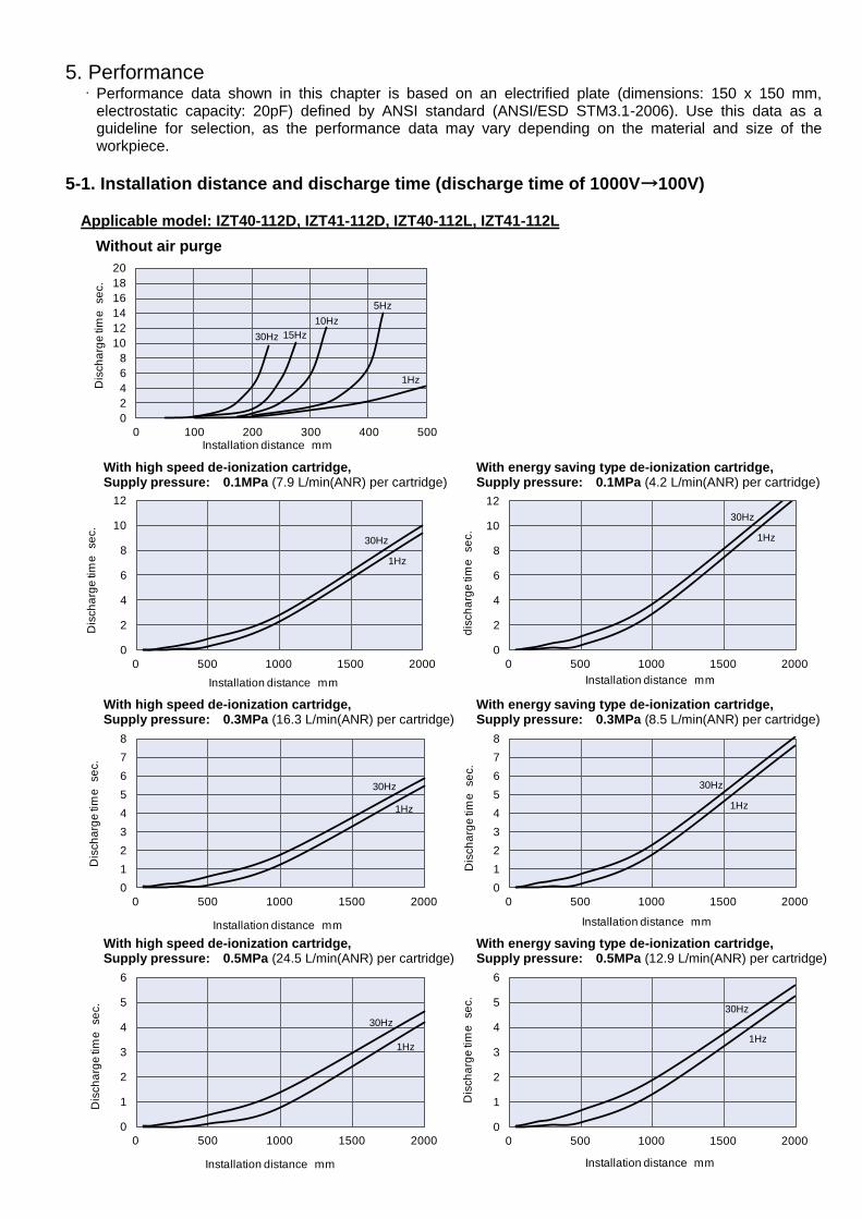
61
5. Performance · Performance data shown in this chapter is based on an electrified plate (dimensions: 150 x 150 mm,
electrostatic capacity: 20pF) defined by ANSI standard (ANSI/ESD STM3.1-2006). Use this data as a guideline for selection, as the performance data may vary depending on the material and size of the workpiece.
5-1. Installation distance and discharge time (discharge time of 1000V→100V) Applicable model: IZT40-112D, IZT41-112D, IZT40-112L, IZT41-112L
0
2
4
6
8
10
12
14
16
18
20
0 100 200 300 400 500
Dis
ch
arg
e ti
me
se
c.
Installation distance mm
Without air purge
30Hz 15Hz
10Hz
5Hz
1Hz
0
2
4
6
8
10
12
0 500 1000 1500 2000
Dis
ch
arg
e ti
me
se
c.
Installation distance mm
With high speed de-ionization cartridge, Supply pressure: 0.1MPa (7.9 L/min(ANR) per cartridge)
30Hz
1Hz
0
2
4
6
8
10
12
0 500 1000 1500 2000
dis
ch
arg
e ti
me
se
c.
Installation distance mm
With energy saving type de-ionization cartridge, Supply pressure: 0.1MPa (4.2 L/min(ANR) per cartridge)
30Hz
1Hz
0
1
2
3
4
5
6
7
8
0 500 1000 1500 2000
Dis
ch
arg
e ti
me
se
c.
Installation distance mm
With high speed de-ionization cartridge, Supply pressure: 0.3MPa (16.3 L/min(ANR) per cartridge)
30Hz
1Hz
0
1
2
3
4
5
6
7
8
0 500 1000 1500 2000
Dis
ch
arg
e ti
me
se
c.
Installation distance mm
With energy saving type de-ionization cartridge, Supply pressure: 0.3MPa (8.5 L/min(ANR) per cartridge)
30Hz
1Hz
0
1
2
3
4
5
6
0 500 1000 1500 2000
Dis
ch
arg
e ti
me
se
c.
Installation distance mm
With high speed de-ionization cartridge, Supply pressure: 0.5MPa (24.5 L/min(ANR) per cartridge)
30Hz
1Hz
0
1
2
3
4
5
6
0 500 1000 1500 2000
Dis
ch
arg
e ti
me
se
c.
Installation distance mm
With energy saving type de-ionization cartridge, Supply pressure: 0.5MPa (12.9 L/min(ANR) per cartridge)
30Hz
1Hz

62
Applicable models: IZT42-112D, IZT42-112L
0
2
4
6
8
10
12
14
16
18
20
0 50 100 150 200 250 300
Dis
ch
arg
e ti
me
se
c.
Installation distance mm
Without air purge
30Hz
1Hz
0
2
4
6
8
10
12
14
16
18
20
0 500 1000 1500 2000
Dis
ch
arg
e ti
me
se
c.
Installation distance mm
With high speed de-ionization cartridge, Supply pressure: 0.1MPa (7.9 L/min(ANR) per cartridge)
30Hz
1Hz
0
2
4
6
8
10
12
14
16
18
20
0 500 1000 1500 2000
Dis
ch
arg
e ti
me
se
c.
Installation distance mm
With energy saving type de-ionization cartridge, Supply pressure: 0.1MPa (4.2 L/min(ANR) per cartridge)
30Hz
1Hz
0
2
4
6
8
10
12
0 500 1000 1500 2000
Dis
ch
arg
e ti
me
se
c.
Installation distance mm
With high speed de-ionization cartridge, Supply pressure: 0.3MPa (16.3 L/min(ANR) per cartridge)
30Hz
1Hz
0
2
4
6
8
10
12
0 500 1000 1500 2000
Dis
ch
arg
e ti
me
se
c.
Installation distance mm
With energy saving type de-ionization cartridge, Supply pressure: 0.3MPa (8.5 L/min(ANR) per cartridge)
30Hz
1Hz
0
1
2
3
4
5
6
7
8
0 500 1000 1500 2000
Dis
ch
arg
e ti
me
se
c.
Installation distance mm
With high speed de-ionization cartridge, Supply pressure: 0.5MPa (24.5 L/min(ANR) per cartridge)
30Hz
1Hz
0
1
2
3
4
5
6
7
8
0 500 1000 1500 2000
Dis
ch
arg
e ti
me
se
c.
Installation distance mm
With energy saving type de-ionization cartridge, Supply pressure: 0.5MPa (12.9 L/min(ANR) per cartridge)
30Hz
1Hz

63
5-2. Potential amplitude Applicable models: IZT40-112D, IZT41-112D, IZT40-112L, IZT41-112L Applicable models: IZT42-112D, IZT42-112L
0
25
50
75
100
125
150
175
200
0 500 1000 1500 2000
Po
ten
tia
l am
plitu
de
V
Installation distance mm
With high speed de-ionization cartridge, Supply pressure: 0.3MPa (16.3 L/min(ANR) per cartridge)
30Hz
0.1Hz
0
25
50
75
100
125
150
175
200
0 500 1000 1500 2000
Po
ten
tia
l am
plitu
de
V
Installation distance mm
With energy saving type de-ionization cartridge, Supply pressure: 0.3MPa (8.5 L/min(ANR) per cartridge)
30Hz
0.1Hz
0
250
500
750
1000
1250
1500
1750
2000
0 500 1000 1500 2000
Po
ten
tia
l am
plitu
de
V
Installation distance mm
With energy saving type de-ionization cartridge, Supply pressure: 0.3MPa (8.5 L/min(ANR) per cartridge)
30Hz
1Hz
0
250
500
750
1000
1250
1500
1750
2000
0 500 1000 1500 2000
Po
ten
tia
l am
plitu
de
V
Installation distance mm
With high speed de-ionization cartridge, Supply pressure: 0.3MPa (16.3 L/min(ANR) per cartridge)
30Hz
1Hz

64
5-3. De-ionizing range Applicable models: IZT40-112D, IZT41-112D, IZT40-112L, IZT41-112L
0
50
100
150
200
250
300
-250 -200 -150 -100 -50 0 50 100 150 200 250
Insta
lla
tio
n d
ista
nce
in h
eig
ht f
orm
ion
ize
r to
w
ork
pie
ce
m
m
Installation distance in depth from ionizer to workpiece mm
High speed static neutralization cartridge Supply pressure: 0.3 MPa (16.3 L/min(ANR) per cartridge) Operating frequency: 30Hz
1s
2s 5s
0.5s
250 200 200 250 150 150 100 100 50 50 0 0
50
100
150
200
250
300
-650 -550 -450 -350 -250 -150 -50 50 150 250 350 450 550 650
Insta
lla
tio
n d
ista
nce
in h
eig
ht f
orm
ion
ize
r to
w
ork
pie
ce
m
m
Installation distance in width from ionizer to workpiece mm
1s
2s
5s
0.5s
150 100 0 50 50 0 100 50 150 100 150 50 100 150
0
50
100
150
200
250
300
-250 -200 -150 -100 -50 0 50 100 150 200 250
Insta
lla
tio
n d
ista
nce
in h
eig
ht f
orm
ion
ize
r to
w
ork
pie
ce
m
m
Installation distance in depth from ionizer to workpiece mm
Energy saving static neutralization cartridge Supply pressure: 0.3 MPa (8.5 L/min(ANR) per cartridge) Operating frequency: 30Hz
1s
2s
5s
0.5s
250 200 200 250 150 150 100 100 50 50 0
0
50
100
150
200
250
300
-650 -550 -450 -350 -250 -150 -50 50 150 250 350 450 550 650
Insta
lla
tio
n d
ista
nce
in h
eig
ht f
orm
ion
ize
r to
w
ork
pie
ce
m
m
Installation distance in width from ionizer to workpiece mm
1s
2s
5s
0.5s
150 100 0 50 50 0 100 50 150 100 150 50 100 150
0
50
100
150
200
250
300
Insta
lla
tio
n d
ista
nce
in h
eig
ht f
orm
ion
ize
r to
w
ork
pie
ce
m
m
Installation distance in width from ionizer to workpiece mm
0.5s
1s
2s
5s
150 100 0 50 50 0 100 50 150 100 150 50 100 150
0
50
100
150
200
250
300
0 50 100 150 200 250 300 350 400 450 500
Insta
lla
tio
n d
ista
nce
in h
eig
ht f
orm
ion
ize
r to
w
ork
pie
ce
m
m
Installation distance in depth from ionizer to workpiece mm
250 200 200 250 150 150 100 100 50 50 0
Without air purge Operating frequency: 30Hz
0.5s
1s
2s
5s

65
Applicable models: IZT42-112D, IZT42-112L
0
50
100
150
200
250
300
-250 -200 -150 -100 -50 0 50 100 150 200 250
Insta
lla
tio
n d
ista
nce
in h
eig
ht f
orm
ion
ize
r to
w
ork
pie
ce
m
m
Installation distance in depth from ionizer to workpiece mm
Without air purge Operating frequency: 30Hz
1s
2s
5s
0.5s
250 200 200 250 150 150 100 100 50 50 0 0
50
100
150
200
250
300
-650 -550 -450 -350 -250 -150 -50 50 150 250 350 450 550 650
Insta
lla
tio
n d
ista
nce
in h
eig
ht f
orm
ion
ize
r to
w
ork
pie
ce
m
m
Installation distance in width from ionizer to workpiece mm
1s 0.5s
2s
5s
150 100 0 50 50 0 100 50 150 100 150 50 100 150
0
50
100
150
200
250
300
-250 -200 -150 -100 -50 0 50 100 150 200 250
Insta
lla
tio
n d
ista
nce
in h
eig
ht f
orm
ion
ize
r to
w
ork
pie
ce
m
m
Installation distance in depth from ionizer to workpiece mm
High speed static neutralization cartridge Supply pressure: 0.3 MPa (16.3 L/min(ANR) per cartridge) Operating frequency: 30Hz
1s
2s
5s
0.5s
250 200 200 250 150 150 100 100 50 50 0
0
50
100
150
200
250
300
-650 -550 -450 -350 -250 -150 -50 50 150 250 350 450 550 650
Insta
lla
tio
n d
ista
nce
in h
eig
ht f
orm
ion
ize
r to
w
ork
pie
ce
m
m
Installation distance in width from ionizer to workpiece mm
1s
0.5s
2s
5s
150 100 0 50 50 0 100 50 150 100 150 50 100 150
0
50
100
150
200
250
300
-250 -200 -150 -100 -50 0 50 100 150 200 250
Insta
lla
tio
n d
ista
nce
in h
eig
ht f
orm
ion
ize
r to
w
ork
pie
ce
m
m
Installation distance in depth from ionizer to workpiece mm
Energy saving static neutralization cartridge Supply pressure: 0.3 MPa (8.5 L/min(ANR) per cartridge) Operating frequency: 30Hz
1s
2s
5s
0.5s
250 200 200 250 150 150 100 100 50 50 0
0
50
100
150
200
250
300
-650 -550 -450 -350 -250 -150 -50 50 150 250 350 450 550 650
Insta
lla
tio
n d
ista
nce
in h
eig
ht f
orm
ion
ize
r to
w
ork
pie
ce
m
m
Installation distance in width from ionizer to workpiece mm
1s
0.5s
2s
5s
150 100 0 50 50 0 100 50 150 100 150 50 100 150

66
5-4. Flow - Pressure characteristics High speed static electricity elimination cartridge Energy saving static eliminating cartridge Measuring method schematic
a) Air supply from one side IZT4□-16,22,34,40,46,58 Tube: O.D. ø6 × I.D. ø4
b) Air supply from both sides
IZT4□-64,82,112 Tube: O.D. ø6 × I.D. ø4 IZT4□-130,160,190 Tube: O.D. ø8 × I.D. ø5 IZT4□-232,250 Tube: O.D. ø10 × I.D. ø6.5
0
0.1
0.2
0.3
0.4
0.5
0.6
0 100 200 300 400 500 600 700 800 900 1000
Pre
ssu
re
MP
a
Flow rate L/min(ANR)
16
22
34
40
46
58
64 82 112
130160
190 232
IZT4□-250
0
0.1
0.2
0.3
0.4
0.5
0.6
0 100 200 300 400 500 600
Pre
ssu
re
MP
a
Flow rate L/min(ANR)
46
22
34
16
40
112
130
64
82
58 232
160
190
IZT4□-250
Measures Air supply
Measures pressure
10mm 10mm
Measures Air supply Measures pressure
10mm

67
6. Dimensions Ionizer IZT40, IZT41
Product No. n(pc.) L1(mm)
IZT4□-16 2 160
IZT4□-22 3 220
IZT4□-34 5 340
IZT4□-40 6 400
IZT4□-46 7 460
IZT4□-58 9 580
IZT4□-64 10 640
IZT4□-82 13 820
IZT4□-112 18 1120
IZT4□-130 21 1300
IZT4□-160 26 1600
IZT4□-190 31 1900
IZT4□-232 38 2320
IZT4□-250 41 2500
Emitter cartridge qty. n, bar length L1
Symbol L2(mm)
1 1000
2 2000
3 3000
High voltage cable length L2
One-touch fitting
Straight (mm)
A
ø4 13
ø6 13
ø8 15
ø10 22
ø3/16" 15
ø1/4" 14
ø5/16" 15
ø3/8" 23
Elbow (mm)
B C D
ø4 25 19 90°
ø6 27 21 75°
ø8 29 24 73°
ø10 37 27 71°
ø3/16" 26 20 90°
ø1/4" 27 21 75°
ø5/16" 29 24 73°
ø3/8" 36 27 71°
Inch
Metric
Inch
Metric
Applicable tube O.D.
Applicable tube O.D.
One-touch Fitting
Sp
ace
fo
r
re
mo
va
l/m
oun
ting
th
e c
on
ne
cto
r
Straight
Plug
Elbow
Straight
Elbow
Plug
One-touch Fitting
2xM4x0.7, depth 5
(Same on the opposite side)

68
End bracket /IZT40-BE1 Intermediate bracket/ IZT40-BM1 End bracket /IZT40-BE2 Intermediate bracket/ IZT40-BM2
End bracket 1
Intermediate bracket 1
Angle adjustable (+/-90
o)
Angle adjustable (+/-15
o)
End bracket 2
Intermediate bracket 2
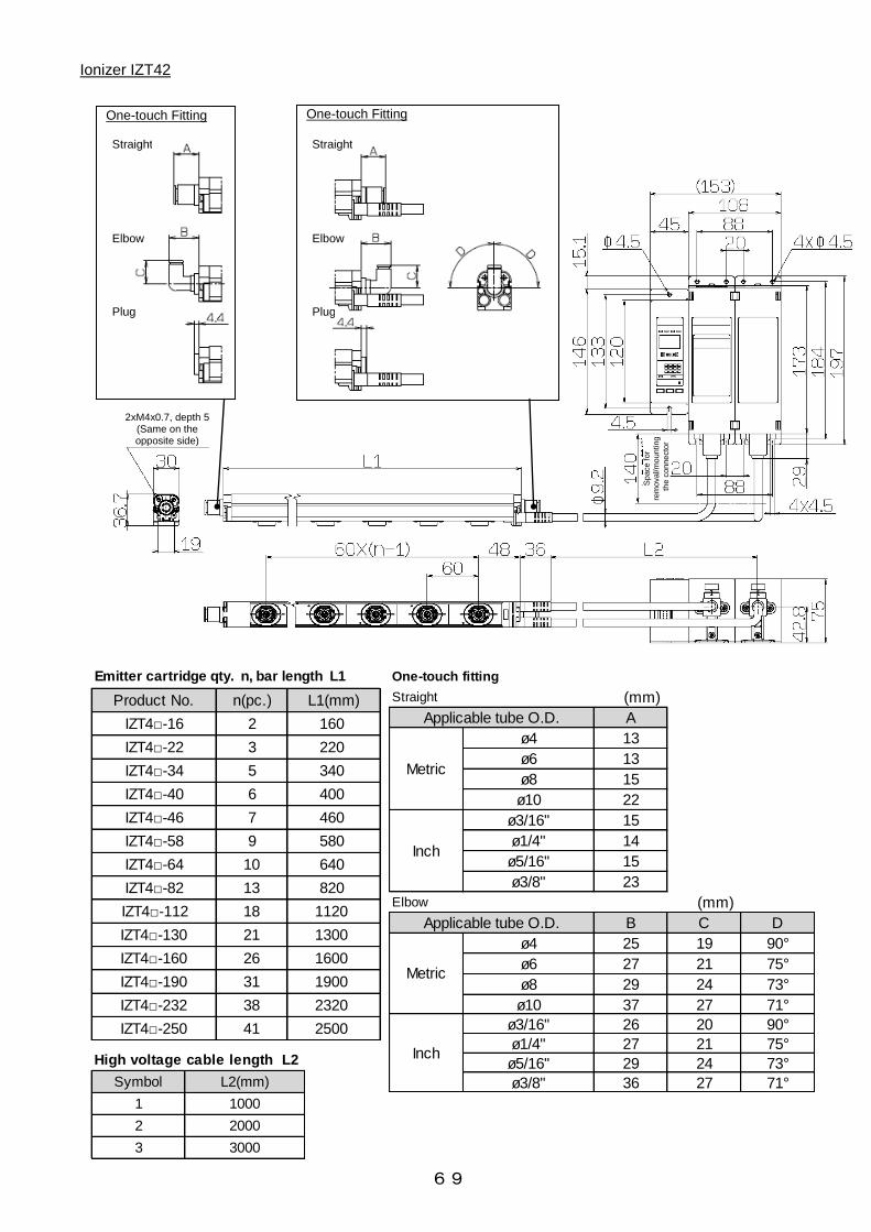
69
Ionizer IZT42
Straight
Plug
One-touch Fitting
Elbow
Sp
ace
fo
r
rem
ova
l/m
oun
ting
th
e c
on
ne
cto
r
Elbow
Straight
Plug
One-touch Fitting
2xM4x0.7, depth 5 (Same on the opposite side)
Product No. n(pc.) L1(mm)
IZT4□-16 2 160
IZT4□-22 3 220
IZT4□-34 5 340
IZT4□-40 6 400
IZT4□-46 7 460
IZT4□-58 9 580
IZT4□-64 10 640
IZT4□-82 13 820
IZT4□-112 18 1120
IZT4□-130 21 1300
IZT4□-160 26 1600
IZT4□-190 31 1900
IZT4□-232 38 2320
IZT4□-250 41 2500
Emitter cartridge qty. n, bar length L1 One-touch fitting
Straight (mm)
A
ø4 13
ø6 13
ø8 15
ø10 22
ø3/16" 15
ø1/4" 14
ø5/16" 15
ø3/8" 23
Elbow (mm)
B C D
ø4 25 19 90°
ø6 27 21 75°
ø8 29 24 73°
ø10 37 27 71°
ø3/16" 26 20 90°
ø1/4" 27 21 75°
ø5/16" 29 24 73°
ø3/8" 36 27 71°
Inch
Metric
Inch
Metric
Applicable tube O.D.
Applicable tube O.D.
Symbol L2(mm)
1 1000
2 2000
3 3000
High voltage cable length L2

70
End bracket /IZT40-BE1 Intermediate bracket/ IZT40-BM1 End bracket /IZT40-BE2 Intermediate bracket/ IZT40-BM2
End bracket 1
Intermediate bracket 1
Angle adjustable (+/-90
o)
Angle adjustable (+/-15
o)
End bracket 2
Intermediate bracket 2

71
Controller IZTC40, IZTC41, IZTC41-P
When DIN rail mounting bracket (IZT40-B1) is used
When power supply cable is inserted

72
High voltage power supply module (IZTP40, IZTP41) When DIN rail mounting bracket (IZT40-B2) is used

73
High voltage power supply module (IZTP42) When DIN rail mounting bracket (IZT40-B3) is used

74
Power supply cable IZS40-CP□ Separate cable IZT40-CF□ Space for mounting/removal of the separate cable and high voltage connector
Product No. L4(mm)
IZT40-CF1 1000
IZT40-CF2 2000
IZT40-CF3 3000
Cable length L4
Sheath
Cable specification
Conductor
Insulator
Number of wire /size
Nominal cross section
O.D.
O.D.
Material
O.D.
Lead free PVC
6.2mm
0.7mm, white, green, pink, purple, gray, yellow, orange, black
12 cables/AWG20(4pcs. ), AWG(8pcs.)
0.54mm2(4pcs.), 0.09mm2(8 pcs.)
0.96mm (4pcs. ), 0.38mm (8pcs. )
1.4mm, brown, blue
Product No. L3(mm)
IZT40-CP3 2950
IZT40-CP5 5000
IZT40-CP10 9800
IZT40-CP15 15000
Cable length L3
Shield wire Semi-stripped terminal
IZTC40/IZTC41 IZTP40/IZTP41 IZTP42
Space for removal/
mounting the connector
Space for removal/
mounting the connector Space for removal/
mounting the connector Space for removal/
mounting the connector Space for removal/
mounting the connector

75
Cable holder (straight) IZT40-E1 Cable holder (elbow) IZT40-E2
AC adapter IZT40-CG1( with AC cord)
IZT40-CG2 (without AC cord)
Section A-A (1:1)
(Recommended screw: Cross recessed round head screw M4 x 5)
Section A-A (1:1)
(Recommended screw: Cross recessed round head screw M4 x 8)
(Recommended screw: Cross recessed round head screw M4 x 8)
(Recommended screw: Cross recessed round head screw M4 x 8)
AC adapter
Inlet IEC60320-C6
AC adapter
AC cord

76
7. Specifications Ionizer Note77) Apply cathode or anode to DC. Note78) With air purge at a distance of 300mm between the workpiece and ionizer
Weight Emitter Cartridge qty., bar weight AC adapter(Sold separately)
Models IZT40-CG1, IZT40-CG2
Input voltage AC100-240V, 50/60Hz
Output current 1.9A
Ambient temperature 0 to 40oC
Ambient humidity 35 to 65%Rh (no condensation)
Weight 375g
Applicable standard/directive CE, cUL
(g)
16 22 34 40 46 58 64 82 112 130 160 190 232 250
2 3 5 6 7 9 10 13 18 21 26 31 38 41
High voltage cable 1m 360 420 530 590 650 760 820 990 1270 1440 1720 2010 2410 2580
High voltage cable 2m 490 550 660 720 780 890 950 1120 1400 1570 1850 2140 2540 2710
High voltage cable 3m 610 670 780 840 900 1010 1070 1240 1520 1690 1970 2260 2660 2830
High voltage cable 1m 520 580 690 750 810 920 980 1150 1430 1600 1880 2170 2570 2740
High voltage cable 2m 770 830 940 1000 1060 1170 1230 1400 1680 1850 2130 2420 2820 2990
High voltage cable 3m 1010 1070 1180 1240 1300 1410 1470 1640 1920 2090 2370 2660 3060 3230
IZT40
IZT41
(common for bars)
Symbol for bar length
Emitter cartridge qty. (pcs.)
IZT42
(g)
Controller High voltage power supply module
IZT40 210 800
IZT41 210 800
IZT42 210 1590
IZT40 IZT41(NPN type) IZT41(PNP type) IZT42(NPN type) IZT42(PNP type)
Fluid
Max. operating
pressure
Proof pressure
0.7A or less
(+0.6A or less per ionizer
when connected)
High voltage abnormality detection
(ion generation stops
when abnormality is detected)
Controller
High voltage power
supply module
Bar
Controller
High voltage power
supply module
Cover : ABS Emitter cartridge: PBT Emitter: Tungsten or monocrystal silicon High Voltage cable: Silicone rubber, PVC
CE(EMC directive)
Ambient humidity
Material
Bar
Applicable standard
35 to 80%Rh (no condensation)
Cover : ABS, Aluminium, switch : Silicone rubber
Cover : ABS, aluminium
Ambient and
fluid
temperature
0 to 40oC
0 to 50oC
50 to 2000mm
Auto balance, maintenance detection, high voltage abnormality detection (ion generation stops when abnormality is detected),
ion generation stop input.
Effective static neutralizing
distance
Function
Air purge
Connected tube
O.D. (One side
can be plugged)
Error signal
-
Max. load current : 100mA
Residual voltage : 1V or less
(at : 100mA of load current)
Max. supply voltage: 26.4 VDC
(+0.7A or less per ionizer when connected)
Max. load current : 100mA
Residual voltage : 1V or less
(at 100mA of load current)
Maintenance
detection signal
AC, DCNote77) Dual AC
+/- 7,000V +/- 6,000V
Corona discharging method
Model
Ion generating method
Voltage application method
Applied voltage
Offset voltage Note78)
1.4A or less
Within +/-30V
Air (Clean and dry)
0.5 MPa or less
0.7MPa
(+1.3A or less per ionizer when connected)Current consumption
Input signal
Output signal
In mm: ø4,ø6,ø8,ø10
In inch : ø3/16,ø1/4,ø5/16,ø3/8
DC24V±10% (AC100-240V:AC adapter option Applicable when only one bar is used)
Max. load current : 100mA
Residual voltage : 1V or less
(at : 100mA of load current)
Max. supply voltage: 26.4 VDC
Max. load current : 100mA
Residual voltage : 1V or less
(at 100mA of load current)
Power supply voltage
-
Connected with DC(-)
Voltage range : 5 VDC or less
Current consumption:
5mA or less
Connected with DC(+)
Voltage range: 19 VDC to
supply voltage
Current consumption:
5mA or less
Connected with DC(-)
Voltage range : 5 VDC or less
Current consumption:
5mA or less
Connected with DC(+)
Voltage range: 19 VDC to
supply voltage
Current consumption:
5mA or less
Ion generation
stop signal
0.8A or less

77
8. Troubleshooting
IZT
40
IZT
41
IZT
42
○○
○T
he
pro
duct d
oe
s n
ot tu
rn O
N
(LE
D is O
FF
)P
ow
er
sup
ply
inco
rre
ctly
wir
ed
Che
ck the
po
we
r sup
ply
wir
ing
.
Che
ck the
co
nne
ctio
n o
f 2
bro
wn w
ire
s D
C(+
) a
nd
2 b
lue
wir
es D
C(-
).E
nsure
all
co
nne
ctio
ns a
re in a
cco
rda
nce
with 3
-2. W
irin
g.
○○
○H
igh v
olta
ge
ca
ble
is n
ot co
nne
cte
d to
the
hig
h v
olta
ge
po
we
r sup
ply
mo
dule
.C
he
ck is h
igh v
olta
ge
ca
ble
is c
onne
cte
d to
the
hig
h v
olta
ge
po
we
r sup
ply
mo
dule
.C
onne
ct hig
h v
olta
ge
ca
ble
to
the
hig
h v
olta
ge
po
we
r sup
ply
mo
dule
.
○○
○C
PU
ma
lfunctio
n c
ause
d b
y no
ise
1)
Che
ck if th
ere
is a
ny
hig
h c
urr
ent e
quip
me
nt in
sta
lled
ne
ar
the
io
niz
er
2)
Che
ck if th
e p
ow
er
sup
ply
ca
ble
or
the
se
pa
rate
ca
ble
is r
oute
d to
ge
the
r w
ith a
ny
hig
h p
ow
er
ca
ble
.
1)
If a
ny
hig
h c
urr
ent e
quip
me
nt is
ne
arb
y, e
ithe
r m
ove
it a
wa
y o
r co
nsid
er
an a
ltern
ative
loca
tio
n fo
r th
e io
niz
er.
2)
Ro
ute
the
io
niz
er
wir
ing
se
pa
rate
ly to
hig
h p
ow
er
ca
ble
s.
3)
Insta
ll a
no
ise
filt
er
to the
co
ntr
olle
r p
ow
er
sup
ply
.
○○
○E
rro
r co
de
"E
1"
dis
pla
yed
(P
ow
er
sup
ply
fa
ilure
)P
ow
er
sup
ply
vo
ltag
e is o
ut o
f ra
ng
eC
he
ck the
po
we
r sup
ply
inp
ut is
within
the
ra
ng
e o
f 2
4 V
DC
+/-
10
%.
Ensure
the
po
we
r sup
ply
is in the
ra
ng
e o
f 2
4 V
DC
+/-
10
%.
○○
○E
rro
r co
de
"E
2"
dis
pla
yed
(H
igh v
olta
ge
po
we
r sup
ply
mo
dule
CP
U a
bno
rma
lity)
CP
U m
alfu
nctio
n c
ause
d b
y no
ise
1)
Che
ck if th
ere
is a
ny
hig
h c
urr
ent e
quip
me
nt in
sta
lled
ne
ar
the
io
niz
er
2)
Che
ck if th
e p
ow
er
sup
ply
ca
ble
or
the
se
pa
rate
ca
ble
is r
oute
d to
ge
the
r w
ith a
ny
hig
h p
ow
er
ca
ble
.
1)
If a
ny
hig
h c
urr
ent e
quip
me
nt is
ne
arb
y, e
ithe
r m
ove
it a
wa
y o
r co
nsid
er
an a
ltern
ative
loca
tio
n fo
r th
e io
niz
er.
2)
Ro
ute
the
io
niz
er
wir
ing
se
pa
rate
ly to
hig
h p
ow
er
ca
ble
s.
3)
Insta
ll a
no
ise
filt
er
to the
co
ntr
olle
r p
ow
er
sup
ply
.
○○
○E
rro
r co
de
"E
3"
dis
pla
yed
(In
co
rre
ct hig
h v
olta
ge
)A
bno
rma
l hig
h v
olta
ge
dis
cha
rge
1)
Che
ck the
em
itte
r fo
r co
nta
min
atio
n.
2)
Che
ck w
he
the
r th
ere
is a
rcin
g b
etw
ee
n the
ba
r a
nd
wo
rkp
iece
to
be
ne
utr
aliz
ed
.
3)
Che
ck w
he
the
r th
e io
niz
er
is u
se
d in a
n e
nvi
ronm
ent sub
ject to
co
nd
ensa
tio
n o
r m
ois
ture
.
4)
Che
ck the
Hig
h v
olta
ge
co
nne
cto
r fo
r co
nta
min
atio
n.
1)
If d
ust o
r d
irt is
fo
und
on the
em
itte
r, c
lea
n the
em
itte
r re
ferr
ing
to
[9
-2.E
mitte
r m
ain
tena
nce
ala
rm a
nd
cle
anin
g
cyc
les].
2)
If th
ere
is a
rcin
g b
etw
ee
n the
wo
rkp
iece
to
be
ne
utr
aliz
ed
and
the
ba
r, incre
ase
the
dis
tance
be
twe
en the
m u
ntil
arc
ing
no
long
er
occurs
.
3)
The
io
niz
er
must no
t b
e u
se
d in e
nvi
ronm
ents
sub
ject to
co
nd
ensa
tio
n o
r m
ois
ture
.
4)
If d
ust o
r d
irt is
fo
und
on the
co
nne
cto
r, c
lea
n the
co
nne
cto
r.
○○
○E
rro
r co
de
"E
4"
dis
pla
yed
(C
om
munic
atio
n e
rro
r)M
alfu
nctio
n c
ause
d b
y no
ise
1)
Che
ck if th
ere
is a
ny
hig
h c
urr
ent e
quip
me
nt in
sta
lled
ne
ar
the
io
niz
er
2)
Che
ck if th
e p
ow
er
sup
ply
ca
ble
or
the
se
pa
rate
ca
ble
is r
oute
d to
ge
the
r w
ith a
ny
hig
h p
ow
er
ca
ble
.
1)
If a
ny
hig
h c
urr
ent e
quip
me
nt is
ne
arb
y, e
ithe
r m
ove
it a
wa
y o
r co
nsid
er
an a
ltern
ative
loca
tio
n fo
r th
e io
niz
er.
2)
Ro
ute
the
io
niz
er
wir
ing
se
pa
rate
ly to
hig
h p
ow
er
ca
ble
s.
3)
Insta
ll a
no
ise
filt
er
to the
co
ntr
olle
r p
ow
er
sup
ply
.
○○
○E
rro
r co
de
"E
5"
is d
isp
laye
d
(F
an m
oto
r fa
ilure
)T
he
fa
n m
oto
r w
as c
log
ge
d u
p w
ith fo
reig
n m
atte
r.C
he
ck the
fa
n m
oto
r is
ro
tating
fo
r co
olin
g w
hic
h is insta
lled
in the
hig
h v
olta
ge
po
we
r sup
ply
mo
dule
.If
fore
ign m
atte
r is
clo
gg
ed
with the
fa
n m
oto
r, r
em
ove
the
fo
reig
n m
atte
r.
○○
○E
rro
r co
de
"E
6"
dis
pla
yed
(H
igh v
olta
ge
po
we
r sup
ply
mo
dule
inco
nsis
tent )
Hig
h v
olta
ge
po
we
r sup
ply
mo
dule
whic
h c
anno
t b
e
co
nne
cte
d to
the
co
ntr
olle
rC
he
ck the
mo
de
l num
be
r o
f th
e c
ontr
olle
r a
nd
hig
h v
olta
ge
po
we
r sup
ply
mo
dule
.S
ele
ct a
pp
lica
ble
co
ntr
olle
r a
nd
hig
h v
olta
ge
po
we
r sup
ply
mo
dule
re
ferr
ing
to
[1
-1. S
yste
m c
onstr
uctio
n].
○○
○E
rro
r co
de
"E
7"
dis
pla
yed
(D
up
lica
tio
n o
f C
H)
CH
se
ttin
g is d
up
lica
ted
whe
n m
ulti
ple
hig
h v
olta
ge
po
we
r
sup
ply
mo
dule
s a
re c
onne
cte
d to
the
co
ntr
olle
r.
Whe
n m
ulti
ple
hig
h v
olta
ge
po
we
r sup
ply
mo
dule
s a
re c
onne
cte
d to
the
co
ntr
olle
r, m
ake
sure
tha
t th
e C
H n
um
be
r se
t
sw
itch a
re n
ot d
up
lica
ted
.
Ma
ke
sure
tha
t th
e s
et num
be
rs o
f th
e C
H n
um
be
r se
t sw
itch o
f th
e h
igh v
olta
ge
po
we
r sup
ply
mo
dule
are
no
t
dup
lica
ted
.
○○
○E
rro
r co
de
"-
-"
is d
isp
laye
d
(H
igh v
olta
ge
po
we
r sup
ply
mo
dule
no
t co
nne
cte
d)
Hig
h v
olta
ge
po
we
r sup
ply
mo
dule
is n
ot co
nne
cte
d to
the
co
ntr
olle
r.C
he
ck if th
e h
igh v
olta
ge
po
we
r sup
ply
mo
dule
is c
onne
cte
d to
the
co
ntr
olle
r.C
onne
ct th
e h
igh v
olta
ge
po
we
r sup
ply
mo
dule
to
the
co
ntr
olle
r.
○○
○
Whe
n m
ulti
ple
hig
h v
olta
ge
po
we
r sup
ply
mo
dule
s a
re
co
nne
cte
d, th
e n
um
be
r o
f th
em
and
the
num
be
r o
f th
e
co
ntr
olle
r d
isp
lay
are
no
t co
nsis
tent.
Hig
h v
olta
ge
po
we
r sup
ply
mo
dule
s a
re n
ot co
nne
cte
d.
Che
ck if th
e h
igh v
olta
ge
po
we
r sup
ply
mo
dule
s a
re c
onne
cte
d e
ach o
the
r.C
onne
ct th
e h
igh v
olta
ge
po
we
r sup
ply
mo
dule
s e
ach o
the
r. (
Re
fer
to 3
-1. In
sta
llatio
n o
f Io
niz
er
for
de
tails
.)
-○
○E
rro
r co
de
"E
8"
is d
isp
laye
d
(E
rro
r sig
na
l outp
ut o
ver
curr
ent)
Err
or
sig
na
l outp
ut cir
cuit w
ire
d inco
rre
ctly
(A
bno
rma
l
sig
na
l ove
r curr
ent g
ene
rate
d )
Che
ck the
outp
ut sp
ecific
atio
ns (
NP
N/P
NP
) a
nd
wir
ing
of b
lack w
ire
.
-○
○E
rro
r co
de
"E
9"
is d
isp
laye
d
(M
ain
tena
nce
sig
na
l outp
ut o
ver
curr
ent)
Inco
rre
ct w
irin
g o
f th
e m
ain
tena
nce
sig
na
l outp
ut cir
cuit
(Ma
inte
na
nce
sig
na
l ove
r curr
ent g
ene
rate
d)
Che
ck the
outp
ut sp
ecific
atio
ns (
NP
N/P
NP
) a
nd
wir
ing
of w
hite
wir
e.
-○
○N
o o
utp
ut sig
na
lO
utp
ut cir
cuit w
ire
d inco
rre
ctly
Che
ck the
outp
ut sp
ecific
atio
ns (
NP
N/P
NP
) a
nd
wir
ing
of b
lack a
nd
white
wir
es.
Unable to
input a signal
-○
○U
na
ble
to
turn
ON
/OF
F io
n d
icha
rge
sto
p s
igna
lIn
put cir
cuit w
ire
d inco
rre
ctly
Che
ck the
inp
ut sp
ecific
atio
ns (
NP
N/P
NP
) a
nd
wir
ing
of p
ink, g
ray,
ye
llow
and
purp
le w
ire
s.
-○
○IO
N/H
V L
ED
is O
FF
.Io
n g
ene
ratio
n s
top
sig
na
l is inp
ut
Che
ck w
he
the
r th
e io
n g
ene
ratio
n s
top
sig
na
l dis
cha
rge
sto
p s
igna
l (p
ink li
ne
, g
ray
line
, ye
llow
line
, p
urp
les li
ne
) a
re
be
ing
inp
ut.
Whe
n p
erf
orm
ing
ne
utr
aliz
atio
n, d
o n
ot in
put th
e io
n g
ene
ratio
n s
top
sig
na
l.
○○
○Io
n b
ala
nce
(o
ffse
t vo
ltag
e)
is u
nsta
ble
F.G
. is
no
t co
nne
cte
dC
he
ck w
he
the
r F
.G. (g
ree
n w
ire
) is
co
nne
cte
d.
The
io
niz
er
ne
utr
aliz
es s
tatic e
lectr
icity
rela
tive
to
gro
und
, e
nsure
the
gre
en w
ire
alw
ays
ha
s a
gro
und
co
nne
ctio
n o
f
less tha
n 1
00
Ω.
○○
○C
he
ck the
offse
t vo
ltag
e b
y th
e m
ea
sure
me
nt e
quip
me
nt such a
s the
cha
rge
d p
late
.
-○
○C
he
ck the
offse
t vo
ltag
e r
efe
rrin
g to
the
co
ntr
olle
r io
n b
ala
nce
dis
pla
y.
-○
○N
DL
LE
D is O
N.
1)D
ust o
r d
irt o
n the
em
itte
r
2)W
ea
ring
or
bre
aka
ge
of th
e e
mitte
r.E
xam
ine
the
em
itte
r tip
with a
ma
gnifie
r.1
) If
dust o
r d
irt is
fo
und
on the
em
itte
r, c
lea
n the
em
itte
r re
ferr
ing
to
[9
. M
ain
tena
nce
].
2)
If th
e e
mitte
rs a
re w
orn
out o
r d
am
ag
ed
, re
pla
ce
the
em
itte
r ca
rtri
dg
e.
○○
○R
ed
uctio
n o
f io
n g
ene
ratio
n1
)Dust o
r d
irt o
n the
em
itte
r
2)W
ea
ring
or
bre
aka
ge
of th
e e
mitte
r.E
xam
ine
the
em
itte
r tip
with a
ma
gnifie
r.1
) If
dust o
r d
irt is
fo
und
on the
em
itte
r, c
lea
n the
em
itte
r re
ferr
ing
to
[9
. M
ain
tena
nce
].
2)
If th
e e
mitte
rs a
re w
orn
out o
r d
am
ag
ed
, re
pla
ce
the
em
itte
r ca
rtri
dg
e.
○○
○1
) C
om
pre
sse
d a
irflo
w insuffic
ient
2)
Inte
rfe
rence
with a
irflo
w
1)
Che
ck tha
t th
e s
up
ply
pre
ssure
and
flo
w r
ate
are
suffic
ient.
2)
Che
ck if a
n e
xte
rna
l air
flow
co
uld
inte
rfe
re w
ith the
flo
w o
f io
niz
ed
air
fro
m the
io
niz
er.
1)
If flo
w r
ate
is insuffic
ient, c
he
ck the
sup
ply
pre
ssure
or
imp
rove
the
sup
ply
cir
cuit s
uch a
s a
ir p
ipin
g. (R
efe
r to
3-1
.
Insta
llatio
n o
f Io
niz
er
and
5
. P
erf
orm
ance
fo
r d
eta
ils. )
2)
If a
n e
xte
rna
l air
flow
is h
avi
ng
an e
ffe
ct, c
onsid
er
shuttin
g o
ff the
air
flo
w o
r o
the
rwis
e c
ha
ng
ing
the
insta
llatio
n s
o
tha
t io
niz
ed
air
is n
ot in
terf
ere
d w
ith.
○○
○Io
niz
ed
air
blo
cke
d o
r a
bso
rbe
d b
y o
bsta
cle
sC
he
ck tha
t th
ere
are
ob
sta
cle
s w
hic
h c
ould
ab
so
rb io
ns o
n the
pa
th u
se
d fo
r sup
ply
ing
io
niz
ed
air
to
the
wo
rkp
iece
to b
e n
eutr
aliz
ed
.
Ob
jects
be
twe
en the
io
niz
er
and
wo
rkp
iece
to
be
ne
utr
aliz
ed
will
blo
ck o
ff o
r a
bso
rb the
io
niz
ed
air
. E
nsure
the
re a
re
no
ob
jects
be
twe
en, o
r ne
ar
to, th
e io
niz
er
and
wo
rkp
iece
to
be
ne
utr
aliz
ed
.
○○
○T
wo
or
mo
re io
niz
ers
are
insta
lled
clo
se
to
ea
ch o
the
rC
he
ck if io
niz
ed
air
fro
m n
ea
rby
ioniz
ers
is inte
rfe
ring
with tha
t o
f th
e m
ain
io
niz
er,
by
sta
rtin
g a
nd
sto
pp
ing
the
ne
arb
y io
niz
ers
and
se
ein
g if th
e p
erf
orm
ance
of th
e m
ain
io
niz
er
is a
ffe
cte
d.
If io
niz
ers
are
insta
lled
clo
se
to
ge
the
r, the
y m
ay
inte
rfe
re w
ith e
ach o
the
r, a
nd
ca
use
a d
ecre
ase
in p
erf
orm
ance
.
Insta
ll re
ferr
ing
[S
afe
ty In
str
uctio
n M
ounting
]
Po
or
ion b
ala
nce
(o
ffse
t vo
ltag
e)
Ad
justm
ent fa
ilure
of th
e o
ffse
t vo
ltag
eA
dju
st o
ffse
t vo
ltag
e r
efe
rrin
g to
4-4
-4. A
dju
stm
ent m
od
e o
f O
ffse
t V
olta
ge
Ioniz
ed
air
is n
ot re
achin
g the
wo
rkp
iece
to
be
ne
utr
aliz
ed
No/poor neutralizing performanceNo output signalP
rob
lem
Ap
plic
ab
le m
od
el
Sta
tus
Po
ss
ible
ca
us
es
Inv
es
tig
ati
on
me
tho
d a
nd
po
ss
ible
ca
us
es
Co
un
term
ea
su
res
Does not operate
Err
or
co
de
"E
0"
is d
isp
laye
d
(C
ontr
olle
r C
PU
ab
no
rma
lity)

78
9. Maintenance
· If the ionizer is used for an extended period of time, contamination such as dust will stick to the emitters, reducing the static neutralization performance.
· The Emitter contamination detection function is available for the IZT41 and IZT42. When the emitter contamination is detected, clean the emitter.
· In cases where the emitter contamination detection function is not used on the IZS41 or IZS42 or IZT40 is used, perform neutralizing performance test and set a maintenance cycle for periodic cleaning.
· Emitter contamination level is different depending on the installation environment and supply pressure.
· If the maintenance signal is output upon completion of cleaning the emitter, it may not have been cleaned sufficiently or it may be worn or damaged. If the emitters are worn out or damaged, replace the emitter cartridge.
· If the emitter is worn out or damaged, the static electricity elimination performance will decrease.
Cleaning procedure of emitter
· It is highly recommended that the emitter cleaning kit (IZS30-M2) is used to clean the emitter needles.
a. Before cleaning the emitters, shutoff the power and air supply. b. The emitters may be cleaned with the emitter cartridges mounted to the bar or with the cartridges
removed from the bar.
Refer to "Removal procedure of emitter cartridge" shown below for instructions on how to remove the cartridges.
c. The emitter cleaning kit (IZS30-M2) has felt at one end of the tool and rubber-bonded whetstone at the other end of the tool.
Emitter cleaning kit (IZS30-M2)
Removal procedure of emitter cartridge
(1) Rotate 90 degree (2) Pull out
Rubber-bonded whetstone (Green)
· A high voltage generating circuit is mounted onto this product. Verify that the power supply is OFF when performing maintenance.
· When compressed air is supplied to the product, shutoff the supply before performing any maintenance operation.
· Never disassemble or modify the product, as this can cause loss of product functionality and a risk of electric shock and earth leakage.
· Do not touch the end of the emitters. They have a sharp end and touching them directly with your fingers may cause injury.
· Only people who have sufficient knowledge and experience are allowed to clean the emitters.
Warning
Felt (White)

79
· Saturate the felt end of the emitter cleaning tool with alcohol and insert it into the back of the emitter cartridge. Turn the tool for several rotations to thoroughly remove dirt.
· If it is not possible to thoroughly remove the dirt using the felt end of the cleaning tool, the rubber-bonded whetstone should be used in the same procedure as described for that of the felt end.
· If you do not have a cleaning kit, an alcohol saturated cotton ball can be used for cleaning the electrodes. Use caution to prevent damage to the electrode needles.
· The alcohol used should be reagent ethanol class 1 99.5vol% or more.
d. When the emitter cartridges are removed for cleaning, remount them to the ionizer according to the
"Mounting procedure of emitter cartridge" shown below. Make sure that the cartridges are securely mounted. If not, the cartridges may become dislodged when compressed air is supplied to the ionizer.
e. Confirm that the static neutralization performance is maintained after cleaning and remounting of the
cartridges are completed.
Replacement of the felt or rubber-bonded whetstone tips of the emitter cleaning kit
· The felt or rubber-bonded whetstone tips of the emitter cleaning kit should be replaced referring to the procedure below when it becomes dirty, as it will not sufficiently clean the emitter.
a. Remove the felt or the rubber-bonded whetstone tip at the end of the emitter cleaning kit.
b. Insert a new felt or rubber-bonded whetstone tip into the emitter cleaning kit using the reverse
procedure as the removal. The felt and the rubber-bonded whetstone tips are rectangular, and the inserting orientation is specified. The end of the rubber-bonded whetstone tip will stick out of the emitter cleaning kit end for 1mm. Do not push it in too much.
Description Part No. Qty.
Replacement felt pad IZS30-A0201 10
Replacement rubber grindstone IZS30-A0202 1
Emitter cleaning kit
Part number for spare felt/ rubber-bonded whetstone tips
Mounting of the emitter cartridge
(1) Insert the cartridge into the bar so that the longer side of the cartridge is mounted at a right angle to the bar.
2) Rotate the cartridge 90 degrees to match the markings on the bar to those on the cartridge and secure.
Cleaning kit with rubber-bonded whetstone
Cleaning kit with felt
Removing the felt
80
4-14-1, Sotokanda, Chiyoda-ku, Tokyo 101-0021 JAPAN Tel: + 81 3 5207 8249 Fax: +81 3 5298 5362 URL http://www.smcworld.com Note: Specifications are subject to change without prior notice and any obligation on the part of the manufacturer. © 2011 SMC Corporation All Rights Reserved
Revision history