
Convection Vacuum Gauge Module The Stinger Instruction Manual
Ionization Gauge / Dual Convection With
Integrated Controller &
Display
392 Series Ionization Vacuum Gauge
User’s Manual
May 2009 Rev. 1.09
Instruction Manual Kurt J. Lesker Company 392 Series Ionization Vacuum Gauge Module
Kurt J. Lesker Company 1925 Worthington Avenue
Clairton, PA 15025 Phone 412-387-9200 Fax 412-384-2745
E-mail [email protected]
Kurt J. Lesker Company page 2

Instruction Manual Kurt J. Lesker Company 392 Series Ionization Vacuum Gauge Module
Table of Contents Introduction / General Information Page Description 5 Specifications 6 Safety General 7 Service and Operation 7 Electrical Conditions 8 Overpressure 9 Installation Mechanical – Ionization Gauge 10 Position 10 Vibration 10 Dimensions 11 Electrical – Ionization Gauges 12 Analog Connector & Pinouts 13 RS485 Connector & Pinouts 14 Mechanical – Convection Gauges 15 Position 15 Vibration 15 Dimensions 16 Electrical – Convection Gauges 16 Analog & Setpoint Relays - CGs 17 Bakeout 18 Setup & Operation Turning on Power to KJLC392 19 Gas Correction Factors 19 Emission Current 19 Overpressure Shut down 19 Degas 20 Activating the KJLC392 20 User Interface User Interface Basics 21 Factory-set Default Parameters 22 Menu Item Explanations 24 SETUP DISP 24 SETUP UNIT 28 SETUP IG 30 SETUP CGS 31 SETUP COMMS 32 SERVICE MENU 33 RS485 Interface RS485 Commands 33
Kurt J. Lesker Company page 3
Instruction Manual Kurt J. Lesker Company 392 Series Ionization Vacuum Gauge Module
Table of Contents - Continued Analog Outputs – N2 & Air only Page IG Only - Log-Linear 44 IG + CG1 - Log-Linear 45 CG1 & CG2 - Log-Linear 46 CG1 & CG2 - Non-Linear 47 Effects of Different Gases on Display
Display Correction Factors - IG 48 Display Conversion - CG 49 Display Correction Factors – IG + CG1 combination Mode 50,51 Effects of Different Gases on Analog Output
Analog Output Correction Factors - IG 52 Analog Output Correction Factors – IG + CG1 combination Mode 53,54 Analog Output Correction Factors – CG1 & CG2 Log-Linear 55 Analog Output Correction Factors – CG1 & CG2 Non-Linear 56 Service & Maintenance
Calibration 57 Troubleshooting - Operation 57 Troubleshooting - Error Messages 58 Sensor Replacement 59 Support, Warranty, Trademarks
Warranty 60
Kurt J. Lesker Company page 4
Instruction Manual Kurt J. Lesker Company 392 Series Ionization Vacuum Gauge Module
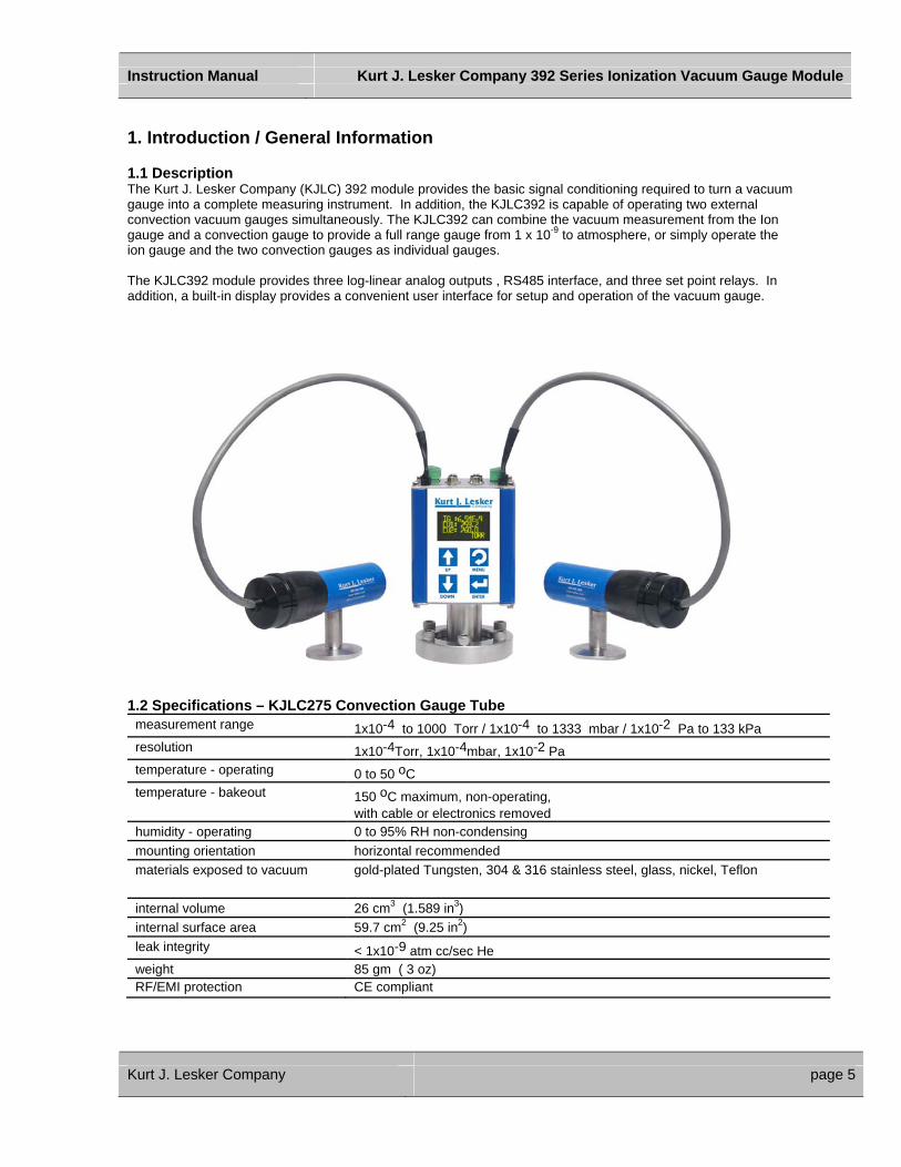
1. Introduction / General Information 1.1 Description The Kurt J. Lesker Company (KJLC) 392 module provides the basic signal conditioning required to turn a vacuum gauge into a complete measuring instrument. In addition, the KJLC392 is capable of operating two external convection vacuum gauges simultaneously. The KJLC392 can combine the vacuum measurement from the Ion gauge and a convection gauge to provide a full range gauge from 1 x 10⁻⁹ to atmosphere, or simply operate the ion gauge and the two convection gauges as individual gauges.
The KJLC392 module provides three log-linear analog outputs , RS485 interface, and three set point relays. In addition, a built-in display provides a convenient user interface for setup and operation of the vacuum gauge.
1.2 Specifications – KJLC275 Convection Gauge Tube
measurement range 1x10⁻⁴ to 1000 Torr / 1x10⁻⁴ to 1333 mbar / 1x10⁻² Pa to 133 kPa resolution 1x10⁻⁴Torr, 1x10⁻⁴mbar, 1x10⁻² Pa temperature - operating 0 to 50 oC temperature - bakeout 150 oC maximum, non-operating,
with cable or electronics removed humidity - operating 0 to 95% RH non-condensing mounting orientation horizontal recommended materials exposed to vacuum gold-plated Tungsten, 304 & 316 stainless steel, glass, nickel, Teflon
internal volume 26 cm3 (1.589 in3) internal surface area 59.7 cm2 (9.25 in2) leak integrity < 1x10⁻⁹ atm cc/sec He weight 85 gm ( 3 oz) RF/EMI protection CE compliant
Kurt J. Lesker Company page 5

Instruction Manual Kurt J. Lesker Company 392 Series Ionization Vacuum Gauge Module
Specifications – KJLC392 Ionization Gauge measurement range: Ionization 1 x 10⁻⁹ to 5 x 10⁻² Torr / 1.3 x 10⁻⁹ to 6.7 x 10⁻² mbar / 1.3 x 10⁻⁷ to 6.7 Pa
Convection 1x 10⁻⁴ to 1000 Torr / 1x10⁻⁴ to 1333 mbar / 1x10⁻² Pa to 133 kPa used as a full range measurement gauge 1 x 10⁻⁹ to 1000 Torr / 1.3 x 10⁻⁹ to 1333 mbar / 1.3 x 10⁻⁷ Pa to 133 kPa display OLED graphical display, 3 digits plus 2 digits exponent, bright yellow functionality Ionization gauge can operate up to 2 Convection gauges materials exposed to gases Dual Filaments: Yttria Coated Iridium
Ion Collector: Tungsten Grid: Tantalum Others: 316/304 SS, Glass, Nickel accuracy (typical) Ionization Convection
±20% of Reading from 1 x 10⁻⁸ to 5 x 10⁻² Torr ±10% of Reading from 1 x 10⁻³ to 400 Torr; ±2.5% of Reading from 400 Torr to atm
sensitivity Factory pre-set. Also user adjustable between 2 to 99. X ray limit < 5 x10⁻¹⁰
emission current 0.1, 4 mA degas 3 Watts e-beam overpressure protection Gauge turns off at factory default setting of 5 X 10⁻² Torr internal gauge volume 1.0 in3 (16.4 cm3 ) operating temperature 0 to + 40o C bakeout temperature 200o C (sensor only - electronics removed) humidity 0 to 95% RH non-condensing weight 0.6 Lbs (0.27 kg) with NW25 KF flange mounting orientation Any digital interface RS485 analog outputs (3 total) Ionization Convection vacuum gauges 1 & 2
One log-linear 0 to 9 Vdc, 1 V/decade or one log-linear 0.5 to 7 Vdc, 0.5 V/decade when used as a full range gauge with one Convection gauge Two log-linear 1-8 Vdc, 1 V/decade or non-linear 0.375 to 5.659 Vdc
setpoint relays (3 total)
Three single-pole, double-throw (SPDT), 1A at 30 Vdc resistive, 0.3 A at 125 Vac non-inductive. Adjust setpoints using front panel push buttons or RS-485
status outputs Degas & filament on/off status are determined by an open collector transistor or via RS485 digital communications protocol
input signal/controls Degas and filament on/off & emission current are set by continuity to ground using digital inputs, via RS485 or manually via front panel push buttons
filament selection User selectable between filament 1 or 2 using the front panel push buttons or via RS485 commands
input Power 20 to 28 Vdc, 15 W RF/EMI protection CE marked, compliant with EMC Directive 89/336/EEC Convection gauge compatibility KJLC275 Tube or Granville Phillips 275 Convectron®
Convection gauge cables One 10 foot cable is included. See order info below for additional cables Convection gauge specifications Refer to KJLC275 Convection Gauge Tube specifications
Part Numbers KJLC392 Module Ion Gauge Module Convection Gauge Replacement Ion With Fitting: Cable Assembly Gauge Sensors NW16KF KJLC392402YB HB431-1-10F (10-FT) IG4YB NW25KF KJLC392402YC HB431-1-25F (25-FT) IG4YC NW40KF KJLC392402YD HB431-1-50F (50-FT) IG4YD 1-1/3" / NW 16CF Mini- Conflat® KJLC392402YE > 50 ft – Consult Factory IG4YE 2-3/4" CF / NW35CF Conflat® KJLC392402YF IG4YF
Kurt J. Lesker Company page 6
Instruction Manual Kurt J. Lesker Company 392 Series Ionization Vacuum Gauge Module
2. Safety KJLC has designed and tested this product to provide safe and reliable service, provided it is installed and operated within the strict safety guidelines provided in this manual. Please read and follow all warnings and instructions. Failure to comply with these safety procedures may result in serious bodily harm, including death, and/or property damage. Failure to comply with these warnings violates the safety standards of the installation and intended use of the instrument. KJLC disclaims all liability for the customer’s failure to comply with these requirements. Although every attempt has been made to consider most possible installations, KJLC cannot anticipate every contingency that arises from various installations, operation, or maintenance of the module. If you have any questions about the safe installation and use of this product, please contact KJLC at the address shown on page 2 of this manual. 2.1 Service and Operation Do not modify this product or substitute any parts without authorization from a qualified KJLC technician. Return the product to an KJLC qualified service and repair center to ensure that all safety features are maintained. Do not use this product if unauthorized modifications have been made. Do not use this device in an explosive atmosphere or in the presence of flammable gases or fumes. Do not use this device to measure the pressure of explosive or combustible gases or mixtures. The sensor filaments operate at incandescent temperatures and could become an ignition source. KJLC gauges and modules are calibrated for use in Nitrogen/Air. Other gases may be used with correction factors. Ensure the unit is properly connected to earth ground. Do not turn on Filaments when pressure exceeds 1.00 x10⁻³ Torr at 4 ma emission current. Do not turn on Filaments when pressure exceeds 5.0 x10⁻² Torr at 0.1 ma (100uA) emission current. Ensure vacuum level is at or less than 5.0 x10⁻⁵ Torr before attempting to initiate Degas. Use the appropriate power source of 20 to 28 Vdc, at 16 W. Turn off power to the unit before attempting to service the module. Do not touch any of the gauge tube pins when under vacuum. Turn off power to the unit before detaching the electronics from the sensor for sensor replacement or bakeout purposes. Turn off power to the unit if a cable or plug is damaged or the product is not operating normally according to this instruction manual. Contact a qualified KJLC technician for any service or troubleshooting condition that may not be covered by this instruction manual. Do not use if unit has been dropped or the enclosure has been damaged. Contact a qualified KJLC technician for possible return to KJLC for evaluation.
Kurt J. Lesker Company page 7
Instruction Manual Kurt J. Lesker Company 392 Series Ionization Vacuum Gauge Module
It is highly recommended to periodically alternate operating filaments 1 and 2. An inactive filament not operating for an extended length of time can cause failure of that filament. This will be more problematic in dirty applications. After servicing this product, ensure that all safety checks are made by a qualified service person. Replacement Parts: When replacement parts are required, ensure that the parts are specified by KJLC, Inc. Unauthorized substitutions or non-qualified parts may result in fire, electric shock, or other hazards, and will void the warranty. To reduce the risk of fire or electric shock, do not expose this product to rain or moisture. This product is not waterproof and careful attention must be paid to not spill any type of liquid onto this product. Due to the possibility of corrosion under certain environmental conditions, it is possible that the product’s safety could be compromised over time. It is important that the product be periodically inspected for sound electrical connections and grounding. Do not use if the grounding or electrical insulation has been compromised. The most common cause of all vacuum gauge failures is contamination of the sensor. Noisy or erratic readings and total gauge failures are all possible indications of gauge contamination. Contamination can generally be characterized as either: A) a reaction of process gases with sensor elements, or B) an accumulation of material on the sensor elements. Sensors that fail due to contamination are not covered under warranty. 2.2 Electrical conditions Danger: When high voltage is present in any vacuum system, a life threatening electrical shock hazard may exist unless all exposed conductors are maintained at earth ground. This applies to all products that come in contact with the gas. Danger: An electrical discharge through a gas may couple dangerous high voltage directly to any ungrounded conductor. A person may be seriously injured or killed by coming in contact with an exposed ungrounded conductor at a high voltage potential. This applies to all products that may come in contact with the gas. Proper Grounding: Verify that the vacuum port on which the module is mounted on is electrically grounded. This is essential for safety as well as proper operation. The gauge and/or case of the module must be connected to earth ground. Use a ground lug on the flange if necessary. Danger: In order to protect personnel from electric shock and bodily harm, shield all conductors which are subject to potential high voltage electrical discharges in or around the vacuum system. Danger: The power supply used in the Ionization Gauge Module (KJLC392) is subject to high voltages which could cause severe injury or death. In order to prevent electric shock and bodily harm, user should wait for at least 5 minutes after power is removed before touching KJLC392’s power supply components. Danger: When the KJLC392 is turned on, 180 V is present at the power supply and other components. Furthermore, voltages as high as 480 V are present during Degas.
Kurt J. Lesker Company page 8

Instruction Manual Kurt J. Lesker Company 392 Series Ionization Vacuum Gauge Module
It is the user’s responsibility to ensure that the electronic signals from the device (Analog Output, relays, etc) are used in a safe manner. Always double check the system set up before using these signals to automate your process. 2.3 Overpressure Warning: Install suitable protective devices such as relief valves or rupture disks that will limit the level of the pressure to less than what the vacuum system can withstand. In cases where an equipment failure could cause a hazardous situation, always implement a fail-safe operation. An example is the use of a pressure relief valve in an automatic backfill operation where a malfunction could result in high internal pressures. The Ionization Gauge should not be exposed to pressures above 1000 Torr.
Kurt J. Lesker Company page 9
Instruction Manual Kurt J. Lesker Company 392 Series Ionization Vacuum Gauge Module
3. Installation 3.1 Ionization Gauge Module (KJLC392) Installation - Mechanical The KJLC392 is intended for indoor use only and it can be mounted anywhere in the system in any physical attitude. Mount the KJLC392 as close as possible to the pressure you want to measure. Long or restricted tubing will create a pressure difference (error) between your process and the gauge, and cause a delay in response to pressure changes. Mounting the KJLC392 too close to a gas source or pump will also cause errors in the readings. Note: You can install the KJLC392 in the upside-down mounting position if desired. The data can be flipped on the display screen by selecting the FLIP SCREEN option from the SETUP DISP menu discussed later in this manual. Don't mount the KJLC392 near a source of heating or cooling, such as heaters or air conditioning vents. Don't mount the KJLC392 where it will be subjected to excessive vibration. Shield the KJLC392 near ion or electron sources such as an electron beam or in a sputtering system. Don’t mount the KJLC392 near strong magnetic fields. These conditions can result in measurement error. Fittings - follow the fitting manufacturer's recommendations and note the following: The KJLC392 is available with the following flanges:
• NW 16KF, NW25KF, NW40KF • 1.33” Mini Conflat, 2.75” Conflat (rotatable)
For safety purposes the housing of the gauge must be grounded to the vacuum chamber. When using the KF flanges, metal clamps must be used to ensure proper grounding. Do not attempt to modify your flange in order to use non-metallic type of flange clamps. Use all metal vacuum fittings when operating pressures are expected to be below 1 x 10⁻⁷ Torr (1.33 x 10⁻⁷ mbar, 1.33 x 10⁻⁵ Pascals)
Kurt J. Lesker Company page 10

Instruction Manual Kurt J. Lesker Company 392 Series Ionization Vacuum Gauge Module
KJLC392 Dimensions
Fitting Dimension A NW16KF 1.45” (37mm) NW25KF 1.45” (37mm) NW40KF 1.45” (37mm) 1-1/3” MiniConflat® 1.85” (47 mm) 2-3/4” Conflat® 1.70” (43 mm)
Figure 1 - KJLC392 Dimensions
Kurt J. Lesker Company page 11
Instruction Manual Kurt J. Lesker Company 392 Series Ionization Vacuum Gauge Module
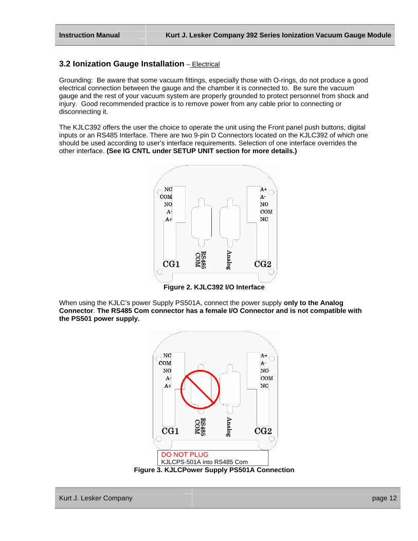
3.2 Ionization Gauge Installation – Electrical Grounding: Be aware that some vacuum fittings, especially those with O-rings, do not produce a good electrical connection between the gauge and the chamber it is connected to. Be sure the vacuum gauge and the rest of your vacuum system are properly grounded to protect personnel from shock and injury. Good recommended practice is to remove power from any cable prior to connecting or disconnecting it. The KJLC392 offers the user the choice to operate the unit using the Front panel push buttons, digital inputs or an RS485 Interface. There are two 9-pin D Connectors located on the KJLC392 of which one should be used according to user’s interface requirements. Selection of one interface overrides the other interface. (See IG CNTL under SETUP UNIT section for more details.)
Figure 2. KJLC392 I/O Interface
When using the KJLC’s power Supply PS501A, connect the power supply only to the Analog Connector. The RS485 Com connector has a female I/O Connector and is not compatible with the PS501 power supply.
DO NOT PLUG KJLCPS-501A into RS485 Com
Figure 3. KJLCPower Supply PS501A Connection
Kurt J. Lesker Company page 12
Instruction Manual Kurt J. Lesker Company 392 Series Ionization Vacuum Gauge Module
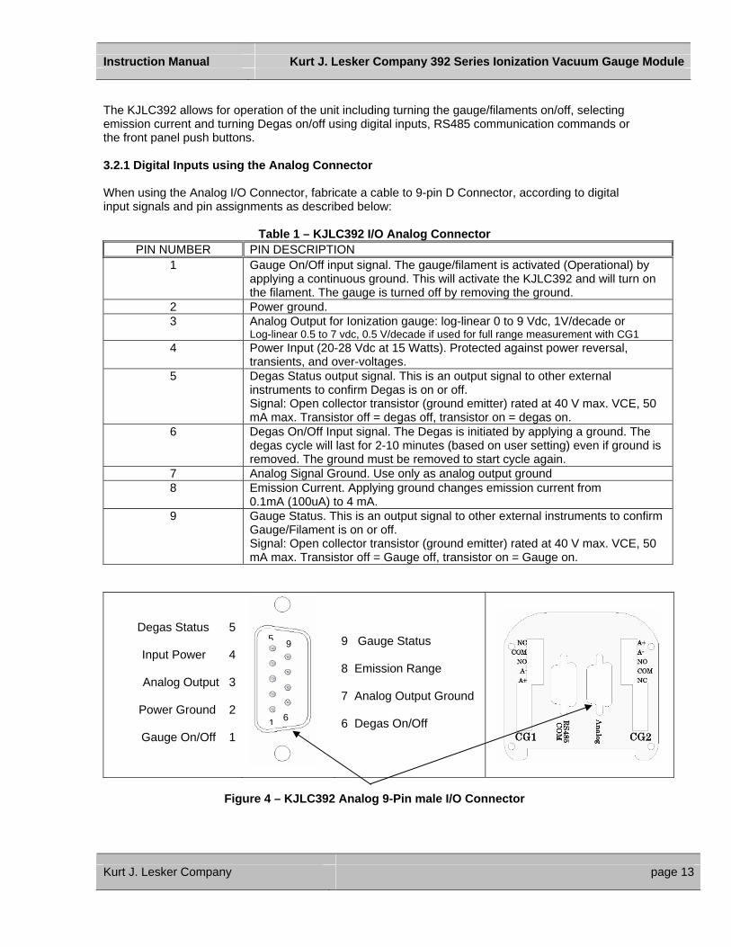
The KJLC392 allows for operation of the unit including turning the gauge/filaments on/off, selecting emission current and turning Degas on/off using digital inputs, RS485 communication commands or the front panel push buttons. 3.2.1 Digital Inputs using the Analog Connector When using the Analog I/O Connector, fabricate a cable to 9-pin D Connector, according to digital input signals and pin assignments as described below:
Table 1 – KJLC392 I/O Analog Connector PIN NUMBER PIN DESCRIPTION
1 Gauge On/Off input signal. The gauge/filament is activated (Operational) by applying a continuous ground. This will activate the KJLC392 and will turn on the filament. The gauge is turned off by removing the ground.
2 Power ground. 3 Analog Output for Ionization gauge: log-linear 0 to 9 Vdc, 1V/decade or
Log-linear 0.5 to 7 vdc, 0.5 V/decade if used for full range measurement with CG1 4 Power Input (20-28 Vdc at 15 Watts). Protected against power reversal,
transients, and over-voltages. 5 Degas Status output signal. This is an output signal to other external
instruments to confirm Degas is on or off. Signal: Open collector transistor (ground emitter) rated at 40 V max. VCE, 50 mA max. Transistor off = degas off, transistor on = degas on.
6 Degas On/Off Input signal. The Degas is initiated by applying a ground. The degas cycle will last for 2-10 minutes (based on user setting) even if ground is removed. The ground must be removed to start cycle again.
7 Analog Signal Ground. Use only as analog output ground 8 Emission Current. Applying ground changes emission current from
0.1mA (100uA) to 4 mA. 9 Gauge Status. This is an output signal to other external instruments to confirm
Gauge/Filament is on or off. Signal: Open collector transistor (ground emitter) rated at 40 V max. VCE, 50 mA max. Transistor off = Gauge off, transistor on = Gauge on.
Degas Status 5
Input Power 4
Analog Output 3
Power Ground 2
Gauge On/Off 1
9 Gauge Status 8 Emission Range 7 Analog Output Ground 6 Degas On/Off
9 5
Figure
Kurt J. Lesker Company
1
4 –
6
KJLC392 Analog 9-Pin male I/O Connector
page 13
Instruction Manual Kurt J. Lesker Company 392 Series Ionization Vacuum Gauge Module
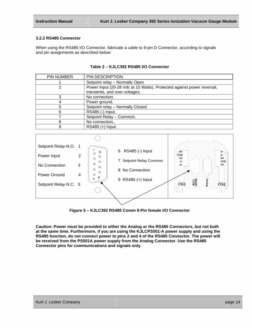
3.2.2 RS485 Connector When using the RS485 I/O Connector, fabricate a cable to 9-pin D Connector, according to signals and pin assignments as described below:
Table 2 – KJLC392 RS485 I/O Connector
PIN NUMBER PIN DESCRIPTION
1 Setpoint relay – Normally Open 2 Power Input (20-28 Vdc at 15 Watts). Protected against power reversal,
transients, and over-voltages. 3 No connection. 4 Power ground. 5 Setpoint relay – Normally Closed 6 RS485 (-) Input. 7 Setpoint Relay – Common. 8 No connection.. 9 RS485 (+) Input.
Setpoint Relay-N.O. 1
Power Input 2
No Connection 3
Power Ground 4
Setpoint Relay-N.C. 5
6 RS485 (-) Input 7 Setpoint Relay Common 8 No Connection 9 RS485 (+) Input
5 9
6 1
Figure 5 –
Caution: Power must be proat the same time. FurthermoRS485 function, do not connbe received from the PS501Connector pins for commun
Kurt J. Lesker Company
KJLC392 RS485 Comm 9-Pin female I/O Connector
vided to either the Analog or the RS485 Connectors, but not both re, if you are using the KJLCPS501-A power supply and using the ect power to pins 2 and 4 of the RS485 Connector. The power will
A power supply from the Analog Connector. Use the RS485 ications and signals only.
page 14
Instruction Manual Kurt J. Lesker Company 392 Series Ionization Vacuum Gauge Module
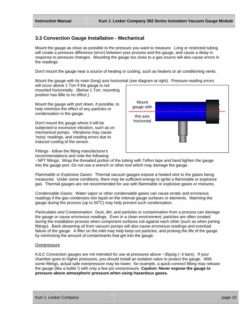
3.3 Convection Gauge Installation - Mechanical Mount the gauge as close as possible to the pressure you want to measure. Long or restricted tubing will create a pressure difference (error) between your process and the gauge, and cause a delay in response to pressure changes. Mounting the gauge too close to a gas source will also cause errors in the readings. Don't mount the gauge near a source of heating or cooling, such as heaters or air conditioning vents. Mount the gauge with its main (long) axis horizontal (see diagram at right). Pressure reading errors will occur above 1 Torr if the gauge is not mounted horizontally. (Below 1 Torr, mounting position has little to no effect.) Mount
gauge with
this axis horizontal
Mount the gauge with port down, if possible, to help minimize the effect of any particles or condensation in the gauge. Don't mount the gauge where it will be subjected to excessive vibration, such as on mechanical pumps. Vibrations may cause 'noisy' readings, and reading errors due to induced cooling of the sensor. Fittings - follow the fitting manufacturer's recommendations and note the following: - NPT fittings: Wrap the threaded portion of the tubing with Teflon tape and hand tighten the gauge into the gauge port. Do not use a wrench or other tool which may damage the gauge. Flammable or Explosive Gases: Thermal vacuum gauges expose a heated wire to the gases being measured. Under some conditions, there may be sufficient energy to ignite a flammable or explosive gas. Thermal gauges are not recommended for use with flammable or explosive gases or mixtures. Condensable Gases: Water vapor or other condensable gases can cause erratic and erroneous readings if the gas condenses into liquid on the internal gauge surfaces or elements. Warming the gauge during the process (up to 50oC) may help prevent such condensation. Particulates and Contamination: Dust, dirt, and particles or contamination from a process can damage the gauge or cause erroneous readings. Even in a clean environment, particles are often created during the installation process when component surfaces rub against each other (such as when joining fittings). Back streaming oil from vacuum pumps will also cause erroneous readings and eventual failure of the gauge. A filter on the inlet may help keep out particles, and prolong the life of the gauge by minimizing the amount of contaminants that get into the gauge. Overpressure KJLC Convection gauges are not intended for use at pressures above ~35psig (~3 bars). If your chamber goes to higher pressures, you should install an isolation valve to protect the gauge. With some fittings, actual safe overpressure may be lower; for example, a quick-connect fitting may release the gauge (like a bullet !) with only a few psi overpressure. Caution: Never expose the gauge to pressure above atmospheric pressure when using hazardous gases.
Kurt J. Lesker Company page 15

Instruction Manual Kurt J. Lesker Company 392 Series Ionization Vacuum Gauge Module
Convection Gauge Dimension Fitting 1/8"NPT - ½" tube NW16KF NW25KF NW40KF 1-1/3" Mini-Conflat®
2-3/4" Conflat®
¼" Cajon® 4VCR ½" Cajon® 8VCR
Dimension A 25.4mm (1.00") 33.0mm (1.30") 33.0mm (1.30") 33.0mm (1.30") 27.4mm (1.08") 21.6mm (0.85") 47.2mm (1.86") 44.5mm (1.75")
90.40 mm (3.56”) 29.00 mm (1.14”) A
Figure 6 – KJLC275 Convection Gauge Tube Dimensions 3.4 Convection Gauge Installation – Electrical Connect your KJLC Convection vacuum gauges or your existing Convectron® gauges to the Hornet KJLC392 using the cables and Connector provided with the instrument. Connect CG1 and CG2 cables to the KJLC392 Connectors marked CG1 and CG2. A good recommended practice is to remove power from any cable prior to connecting or disconnecting it
The KJLC392 provides one analog output and one set-point relay for each one of the Convection gauges connected to it.
Kurt J. Lesker Company page 16
Instruction Manual Kurt J. Lesker Company 392 Series Ionization Vacuum Gauge Module
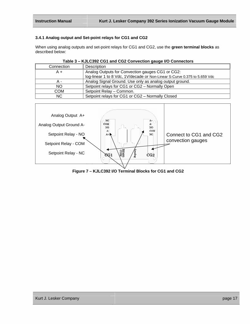
3.4.1 Analog output and Set-point relays for CG1 and CG2 When using analog outputs and set-point relays for CG1 and CG2, use the green terminal blocks as described below:
Table 3 – KJLC392 CG1 and CG2 Convection gauge I/O Connectors Connection Description
A + Analog Outputs for Convection gauges CG1 or CG2: log-linear 1 to 8 Vdc, 1V/decade or Non-Linear S-Curve 0.375 to 5.659 Vdc
A - Analog Signal Ground. Use only as analog output ground. NO Setpoint relays for CG1 or CG2 – Normally Open
COM Setpoint Relay – Common. NC Setpoint relays for CG1 or CG2 – Normally Closed
Analog Output A+
Analog Output Ground A-
Setpoint Relay - NO
Setpoint Relay - COM
Setpoint Relay - NC
Connect to CG1 and CG2 convection gauges
Figure 7 – KJLC392 I/O Terminal Blocks for CG1 and CG2
Kurt J. Lesker Company page 17
Instruction Manual Kurt J. Lesker Company 392 Series Ionization Vacuum Gauge Module
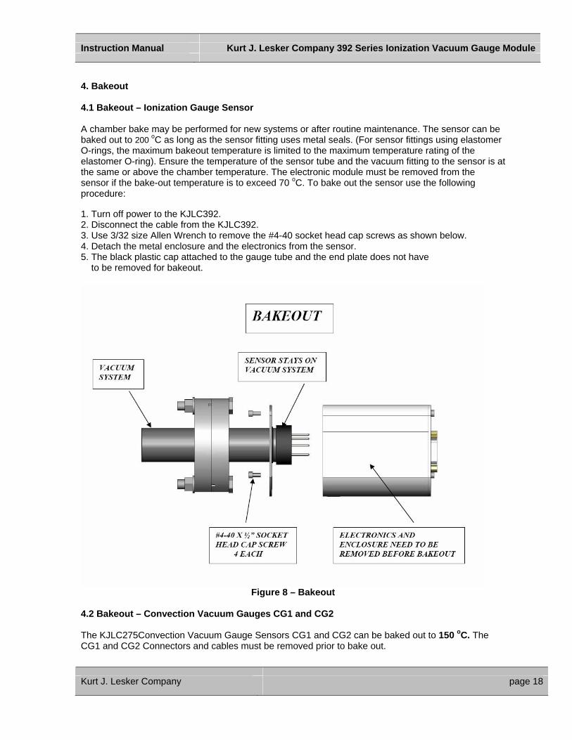
4. Bakeout 4.1 Bakeout – Ionization Gauge Sensor A chamber bake may be performed for new systems or after routine maintenance. The sensor can be baked out to 200 oC as long as the sensor fitting uses metal seals. (For sensor fittings using elastomer O-rings, the maximum bakeout temperature is limited to the maximum temperature rating of the elastomer O-ring). Ensure the temperature of the sensor tube and the vacuum fitting to the sensor is at the same or above the chamber temperature. The electronic module must be removed from the sensor if the bake-out temperature is to exceed 70 oC. To bake out the sensor use the following procedure: 1. Turn off power to the KJLC392. 2. Disconnect the cable from the KJLC392. 3. Use 3/32 size Allen Wrench to remove the #4-40 socket head cap screws as shown below. 4. Detach the metal enclosure and the electronics from the sensor. 5. The black plastic cap attached to the gauge tube and the end plate does not have to be removed for bakeout.
Figure 8 – Bakeout
4.2 Bakeout – Convection Vacuum Gauges CG1 and CG2 The KJLC275Convection Vacuum Gauge Sensors CG1 and CG2 can be baked out to 150 oC. The CG1 and CG2 Connectors and cables must be removed prior to bake out.
Kurt J. Lesker Company page 18
Instruction Manual Kurt J. Lesker Company 392 Series Ionization Vacuum Gauge Module
5. Setup and Operation 5.1 Turning On Power to KJLC392 Connect power to KJLC392 using the designated pins 4 and 2 as shown in Table 1. The display will show “Unit Status Off”. This indicates the display is on but the gauge/filaments have not been activated yet. Read this instruction manual in its entirety before activating the gauge/filaments. Refer to Activating the KJLC392 section for further instructions on activating/operating the gauge/filaments. 5.2 Gas Correction Factors KJLC gauges and modules are calibrated for Nitrogen (N2). If you are using gases other than Nitrogen you must manually apply gas correction factors to the display and outputs measured by the Ionization and Convection gauges. Warning: Use of different gases without proper precautions can result in injury to personel and/or damage to equipment. Post a label on your gauge display indicating correction factors must be applied to both the Ionization and Convection gauge measurements. Read the later sections in this manual regarding the effects of different gases on display and outputs as well as the lists of gas correction factors. 5.3 Emission Current KJLC392 provides a choice of 4 mA or 100 uA (0.1 ma) emission current.
1) As a general rule, in clean applications and operating at higher pressure ranges (5.00E-06 Torr to 5.00E-02 Torr) the 100 uA emission setting is preferred.
2) At lower operating pressures (1.00E-09 Torr to 1.00E-04 Torr) the 4 mA emission should be
used.
3) When using diffusion pumps there is a possibility of the oil vapors entering the gauge sensor tube. This can form an insulator on the internal components of the sensor which can lead to instability or failure in controlling the emission. In this case, the 4 mA emission current may provide for a better operation.
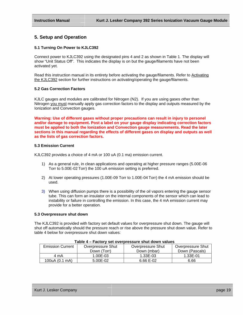
5.3 Overpressure shut down The KJLC392 is provided with factory set default values for overpressure shut down. The gauge will shut off automatically should the pressure reach or rise above the pressure shut down value. Refer to table 4 below for overpressure shut down values:
Table 4 – Factory set overpressure shut down values Emission Current Overpressure Shut
Down (Torr) Overpressure Shut
Down (mbar) Overpressure Shut
Down (Pascals) 4 mA 1.00E-03 1.33E-03 1.33E-01
100uA (0.1 mA) 5.00E-02 6.66 E-02 6.66
Kurt J. Lesker Company page 19

Instruction Manual Kurt J. Lesker Company 392 Series Ionization Vacuum Gauge Module
5.4 Degas Degas is used to rid the gauge sensor tube of adsorbed gas. Degas is achieved by applying Electron Bombardment (EB) to the grid. The intervals at which Degas should be applied vary for each application. The sensor’s low pressure performance will normally improve after each Degas cycle. Degas must be applied while the gauge/filament is activated and operating. Ensure vacuum level is at or less than 5.0 x10⁻⁵ Torr before attempting to initiate Degas. Power during Degas is about 3 watts higher than the normal operating pressure. Degas will automatically turn off after 2 minutes when using factory default settings. The user can however reprogram the KJLC354 for a Degas cycle to last anywhere between 2 to 10 minutes. The KJLC354 will continue to display the measured operating pressure while Degas is proceeding. Degas will automatically turn off if the pressure exceeds 3.0 x10⁻⁴ Torr during the Degas cycle. Degas can be interrupted by turning off the Filament. 5.5 Activating the KJLC392 (Turning the Filaments On) Before you activate the gauge/filament, make sure you understand all instructions and information provided in this manual. You can activate the KJLC392 (gauge/filaments turned on and operating) by one of the following four methods:
1) Front Panel push buttons.
2) Digital Input.
3) By RS-485 commands.
4) When used with a Convection gauge CG1 for full range measurement, activation can be caused by pressure measurement from CG1. (See section on IG CNTL under SETUP UNIT menu).
Initiating filament to turn on will result in only one attempt to activate the gauge/filament operational. If this is unsuccessful, the input must be reset back to off before another attempt is made to turn it on again. See messages on display for possible causes. If the problem persists consider the following possible causes:
• Insufficient power if ITI’s power supply is not used. • System pressure exceeding the overpressure shut down limit or pressure is at a value at
which the emission can not be achieved. • Contamination. • See messages on display for other possible causes.
Note: The filament is also turned off by using one of the four methods listed above.
Kurt J. Lesker Company page 20
Instruction Manual Kurt J. Lesker Company 392 Series Ionization Vacuum Gauge Module
6.User Interface 6.1 User Interface Basics The menus within the KJLC392 user interface have been designed for easy operation and a natural progression of setup parameters. The following sections give a brief explanation of the features for added clarity.
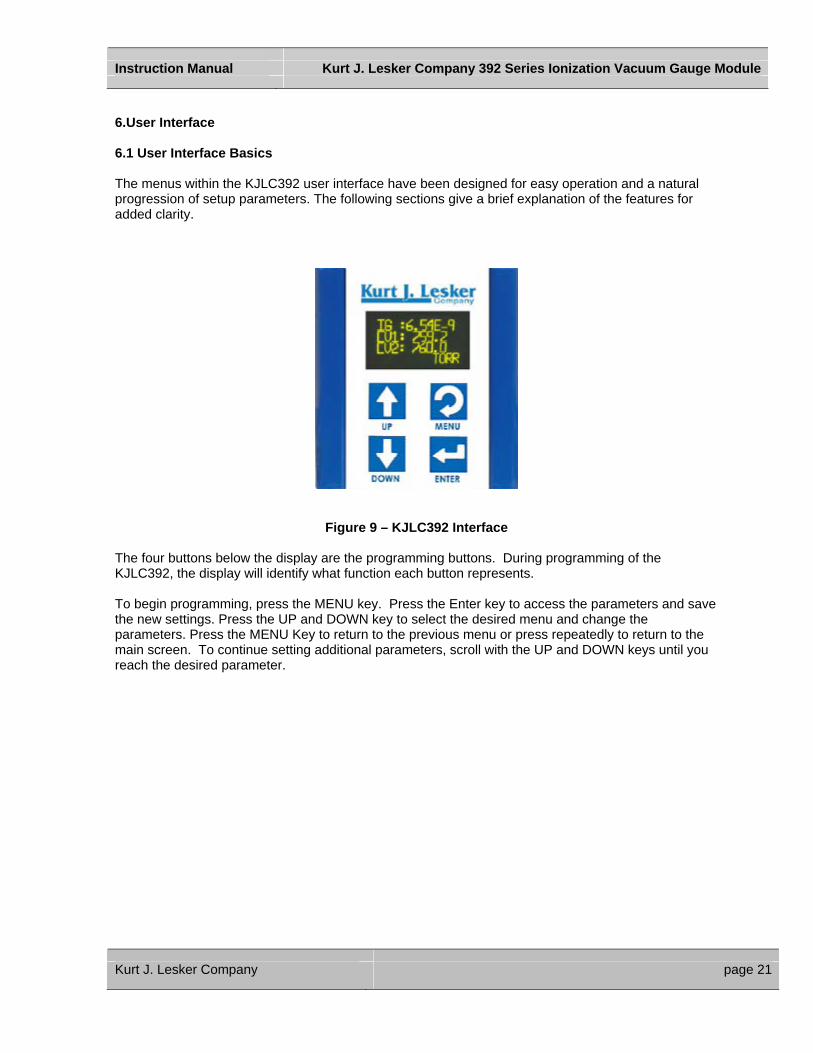
Figure 9 – KJLC392 Interface The four buttons below the display are the programming buttons. During programming of the KJLC392, the display will identify what function each button represents. To begin programming, press the MENU key. Press the Enter key to access the parameters and save the new settings. Press the UP and DOWN key to select the desired menu and change the parameters. Press the MENU Key to return to the previous menu or press repeatedly to return to the main screen. To continue setting additional parameters, scroll with the UP and DOWN keys until you reach the desired parameter.
Kurt J. Lesker Company page 21
Instruction Manual Kurt J. Lesker Company 392 Series Ionization Vacuum Gauge Module
6.2 Factory-Set Default Parameters The following is a summary of all factory-set default values in KJLC392’s display menu. SETUP DISP - SET CONTRAST [Factory default = 10] - SHOW DATA [Factory default = SHOW ALL LG]
- Display INT [Factory default =3 SECONDS] - FLIP SCREEN [Factory default = NORMAL] SETUP UNIT - UNITS [Factory default = TORR] - DEFAULTS [Factory default = MENU TO EXIT] - CLR IG ERROR [Factory default = OFF] - 100UA TRN ON [Factory default = 5.00E-02 TORR] - IG CNTL [Factory default = DIGI/RS485,( Factory default is Digital Input)] - FP OPERATE [Appears only when FRONT PANEL is selected in IG CNTL above] UNIT ON/OFF: [Factory default = OFF]
EMISSION SEL: [Factory default = 100uA] DEGAS ON/OFF: [Factory default = OFF] SETUP IG - DEGAS TIME [Factory default = 2 ] - SENSITIVITY [Factory default = Actual Sensor sensitivity (see label on gauge)] - FILAMENT NUM [Factory default = FILAMENT 1] - RLY I LO TRIP [Factory default = 1.00E-06 TORR] - RLY I HI TRIP [Factory default = 5.00E-06 TORR] - RELAY I TEST Factory default = OFF] - VENT DETECT [Factory default = OFF] - ANALOG MODE [Factory default = IG ONLY] - FIL USAGE [Factory default = Displays to-date current usage] SETUP CGS - RLY A LO TRIP [Factory default = 1.00 E -1 TORR]
- RLY A HI TRIP [Factory default = 2.00 E -1 TORR] - RELAY A TEST [Factory default = OFF] - RLY B LO TRIP [Factory default = 1.00 E -1 TORR] - RLY B HI TRIP [Factory default = 2.00 E -1 TORR] - RELAY B TEST [Factory default = OFF] - ASSIGN RLY A [Factory default = CG1] - ASSIGN RLY B [Factory default = CG2] - SETUP CG 1
SET VAC [Factory default = 0.00E+0 TORR] SET ATM [Factory default = 7.59E+2 TORR] ANALOG TYPE [Factory default = LOG-LINEAR]
- SETUP CG 2 SET VAC [Factory default = 0.00E+0 TORR] SET ATM [Factory default = 7.59E+2 TORR] ANALOG TYPE [Factory default = LOG-LINEAR]
Kurt J. Lesker Company page 22

Instruction Manual Kurt J. Lesker Company 392 Series Ionization Vacuum Gauge Module
SETUP COMMS -BAUD RATE [Factory default = 19200,8,N,1]
-ADDR [Factory default = 1] -ADDR OFFSET [Factory default = 0]
SERVICE MENU -INFO [Factory default = FIRMWARE VERSION] -OP TIME [Factory default = Displays to-date operating Time]
Kurt J. Lesker Company page 23

Instruction Manual Kurt J. Lesker Company 392 Series Ionization Vacuum Gauge Module
6.3 Menu Item Explanations 6.3.1 SETUP DISP
- SET CONTRAST: [Factory default = 10] This function sets the display contrast. Use the ENTER KEY to access the CONTRAST menu and use the UP and DOWN Keys to select a number between 1 and 120. The contrast setting of 120 provides the highest contrast (brightest) and 1 the lowest. Select the ENTER KEY again to save the value selected. (Note: Factory default setting optimizes display life.) - SHOW DATA [Factory default = SHOW ALL LG] Use the ENTER KEY to access the SHOW DATA menu and use the UP and DOWN Keys to select one of the following display modes:
SHOW ALL LG SHOW ALL SM IG + CG1 LG IG+CG1/CG2 IG/CG1 LG IG/CG2 LG CG1/CG2 LG CG1/CG2 SM IG ONLY IG ONLY RND CG1 ONLY CG2 ONLY
Select the ENTER KEY again to save the desired mode selected above.
1. SHOW ALL LG
This mode displays the most commonly used variables from the Ionization Gauge, the CG1 and CG2 convection vacuum gauges in three separate screens. These are the measured pressure, the pressure unit, the gas symbol, filament and relay status. The three screens are displayed sequentially and repeatedly showing the Ion Gauge data first, followed next by screens for CG1 and CG2. In the following examples, the measured pressure from the Ion Gauge is 6.45 x10⁻⁹ Torr, Filament #1 is on, gas is Nitrogen and Relay #1 is on.
Negative Exponent
Indicates Filament # 1 is on Gas Symbol
6.45E 9 Fil:1 TORR N2 RLY I
Measured Pressure Indicates Pressure Unit Indicates Ion gauge Relay I is On*
Ex 1A: Ionization Gauge data displayed in SHOW ALL LG mode
The Ionization Gauge display screen (Example Ex1A) above is followed by the next screen below showing the Convection Gauge 1 (CG1) data after the display interval time has elapsed.
Negative Exponent
Indicates CG1 display screen Gas Symbol
1.00E 3 CG1 TORR N2 RLY A
Measured Pressure Indicates Pressure Unit Indicates Convection Gauge CG1 Relay A is On*
Ex 1B: CG1 data displayed in SHOW ALL LG mode
Kurt J. Lesker Company page 24

Instruction Manual Kurt J. Lesker Company 392 Series Ionization Vacuum Gauge Module
The Convection Gauge 1 data screen (Example Ex1B) is followed by the next screen below showing the Convection Gauge 2 (CG2) data after the display interval time has elapsed.
Indicates CG2 display screen Gas Symbol
760 CG2 TORR N2 RLY B
Measured Pressure Indicates Pressure Unit Indicates Convection Gauge CG1 Relay B is On*
Ex 1C: CG2 data displayed in SHOW ALL LG mode
*Note: RLY I, A & B disappear from the screen in its entirety when those relays are turned off.
The screens repeat each time the programmed display interval time has elapsed.
2. SHOW ALL SM This mode displays the measured pressure from the Ionization Gauge, CG1 and CG2 convection gauges simultaneously in one screen. In the following example, the measured pressure from the Ion Gauge (IG) is 6.45 x10⁻⁹ Torr, the measured pressure from Convection Gauge 1 (CG1) is 1.23 x10⁻² Torr and measured pressure from Convection Gauge 2 (CG2) is 760 Torr.
Negative Exponent
Ion Gauge Measured Pressure CG2 Measured Pressure
IG: 6.45E-9 CG1: 1.23E-2 CG2: 760
TORR
CG1 Measured Pressure Indicates Pressure Unit
EX 2A: IG, CG1 and CG2 data displayed in SHOW ALL SM mode
Note: It may take up to 10 seconds for the KJLC392 filament to turn on after it has received a turn on command from the front panel push buttons, the Digital Inputs, or RS485 commands. The display showing the Ion gauge measurement is blank during this time while KJLC392 is starting the emission and stabilizing the measurements.
Kurt J. Lesker Company page 25
Instruction Manual Kurt J. Lesker Company 392 Series Ionization Vacuum Gauge Module
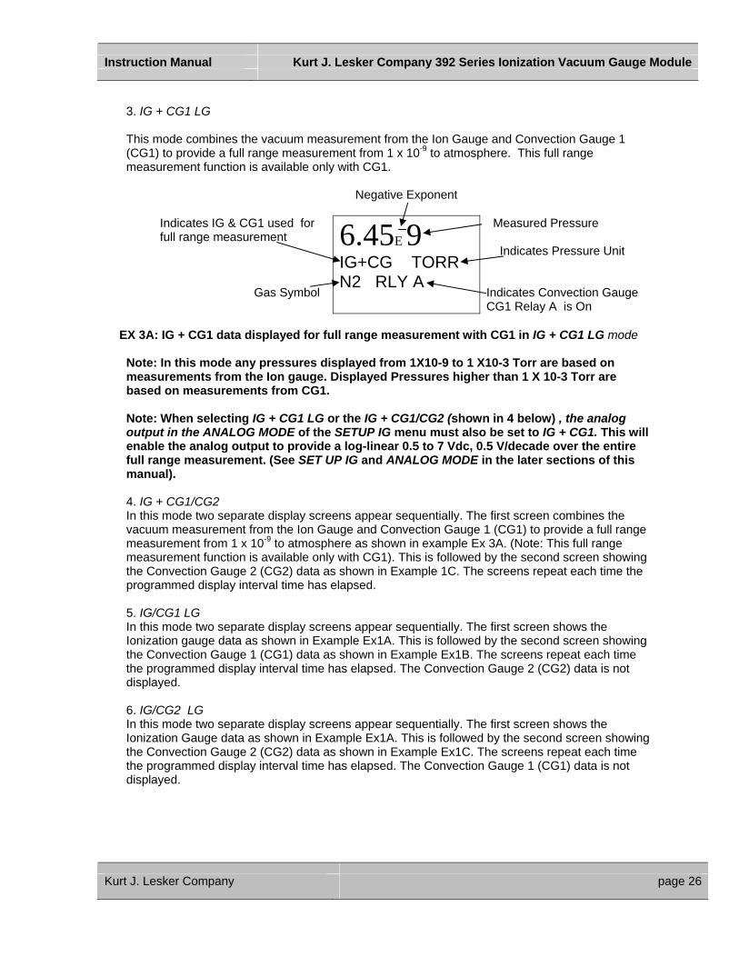
3. IG + CG1 LG
This mode combines the vacuum measurement from the Ion Gauge and Convection Gauge 1 (CG1) to provide a full range measurement from 1 x 10⁻⁹ to atmosphere. This full range measurement function is available only with CG1.
Negative Exponent
Indicates IG & CG1 used for full range measurement Gas Symbol
6.45E 9 IG+CG TORR N2 RLY A
Measured Pressure Indicates Pressure Unit Indicates Convection Gauge CG1 Relay A is On
EX 3A: IG + CG1 data displayed for full range measurement with CG1 in IG + CG1 LG mode
Note: In this mode any pressures displayed from 1X10⁻⁹ to 1 X10⁻³ Torr are based on measurements from the Ion gauge. Displayed Pressures higher than 1 X 10⁻³ Torr are based on measurements from CG1. Note: When selecting IG + CG1 LG or the IG + CG1/CG2 (shown in 4 below) , the analog output in the ANALOG MODE of the SETUP IG menu must also be set to IG + CG1. This will enable the analog output to provide a log-linear 0.5 to 7 Vdc, 0.5 V/decade over the entire full range measurement. (See SET UP IG and ANALOG MODE in the later sections of this manual). 4. IG + CG1/CG2 In this mode two separate display screens appear sequentially. The first screen combines the vacuum measurement from the Ion Gauge and Convection Gauge 1 (CG1) to provide a full range measurement from 1 x 10⁻⁹ to atmosphere as shown in example Ex 3A. (Note: This full range measurement function is available only with CG1). This is followed by the second screen showing the Convection Gauge 2 (CG2) data as shown in Example 1C. The screens repeat each time the programmed display interval time has elapsed. 5. IG/CG1 LG In this mode two separate display screens appear sequentially. The first screen shows the Ionization gauge data as shown in Example Ex1A. This is followed by the second screen showing the Convection Gauge 1 (CG1) data as shown in Example Ex1B. The screens repeat each time the programmed display interval time has elapsed. The Convection Gauge 2 (CG2) data is not displayed. 6. IG/CG2 LG In this mode two separate display screens appear sequentially. The first screen shows the Ionization Gauge data as shown in Example Ex1A. This is followed by the second screen showing the Convection Gauge 2 (CG2) data as shown in Example Ex1C. The screens repeat each time the programmed display interval time has elapsed. The Convection Gauge 1 (CG1) data is not displayed.
Kurt J. Lesker Company page 26

Instruction Manual Kurt J. Lesker Company 392 Series Ionization Vacuum Gauge Module
7. CG1/CG2 LG In this mode two separate display screens appear sequentially. The first screen shows the Convection Gauge 1 (CG1) data as shown in Example Ex1B. This is followed by the second screen showing the Convection Gauge 2 (CG2) data as shown in Example Ex1C. The screens repeat each time the programmed display interval time has elapsed. The Ionization Gauge (IG) data is not displayed. 8. CG1/CG2 SM This mode displays the measured pressure from the CG1 and CG2 Convection gauges simultaneously in one screen as shown in example below:
CG1 Measured Pressure Gas Symbol
CG1:1.23E-2 CG2: 760 TORRN2 RLY A
CG2 Measured Pressure Indicates Pressure Unit Indicates Convection Gauge CG1 Relay A is On
EX8A: CG1 and CG2 data displayed in CG1/CG2 SM mode
9. IG ONLY This mode displays only the measured pressure from the Ionization Gauge in a single screen as shown in Example Ex1A.
10. IG ONLY RND This mode displays the measured pressure, emission current, ion current, filament voltage and filament current. In the following example, the measured pressure is 1.00 x10⁻⁹ Torr, (Pressure unit is based on selected units in SETUP UNIT menu). Emission current is 4.00E-3 amps, Ion current is 4.00 E-11 amps, filament voltage is 1.5 Vdc and filament current is 1.9 amps.
Negative Exponent
Emission current value(amps) Ion current value (amps)
PT= 1.00E-9 IE= 4.00E-3 IC= 4.00E-11FVI 1.5 1.9
Measured Pressure Filament Voltage (Vdc) Filament current (amps)
EX10A: IG data displayed in IG ONLY RND mode
11. CG1 ONLY This mode displays only the measured pressure from Convection Gauge 1 (CG1) in a single screen as shown in Example Ex1B.
Kurt J. Lesker Company page 27
Instruction Manual Kurt J. Lesker Company 392 Series Ionization Vacuum Gauge Module
12. CG2 ONLY This mode displays only the measured pressure from Convection Gauge 2 (CG2) in a single screen as shown in example Ex1C. - DISPLAY INT [Factory default =3 SECONDS] This is the time it takes for display screen to change to the next screen. Display interval can be selected from 2 to 10 seconds.
-FLIP SCREEN [Factory default = NORMAL]
This allows the user to select a NORMAL display or have the data displayed UPSIDE DOWN. When the unit is mounted upside down, this is used to invert the display screen 180 degrees for user convenience. Note: When UPSIDE DOWN is selected, the user has to save the setting and exit the menu before the measured values are displayed upside down.
6.4 SETUP UNIT - UNITS: [Factory default = TORR]
Select from Torr, mbar or Pascal. Units selected are used for all other settings. - DEFAULTS: [Factory default =MENU TO EXIT] The module can be returned to the original factory settings by using the ENTER Key to set factory defaults. Note: You must re-enter the actual sensor sensitivity value marked on the sensor tube. - CLR IG ERROR [Factory default = OFF] When KJLC392 experiences an error condition such as overpressure, emission failure, etc, the Ion gauge filaments will turn off. Error messages will be displayed on the IG screen showing the error. This is intended to prompt the user to determine what the error condition is before the filaments can be turned on again. Once the cause of the error has been determined and resolved, the KJLC392 error must be cleared before the filaments can be turned on again. The CLR IG ERROR allows the user to clear the IG error using the front panel, regardless of whether the IG CNTL mode below is set to Front Panel, Digital Input, RS485 or CG1 CONT IG.
- 100UA TRN ON [Factory default = 5.00E-02 TORR] This allows the user to select a pressure value at which the CG1 can turn on the IG. This is applicable only when the gauge is operating at 100uA emission current setting and the IG CNTL mode below is set to CG1 CONT IG. The 100UA TRN ON pressure value can never be set higher than 5.00E-02 TORR when operating in the 100UA emission current setting. Note: The user does not have the choice to select a turn on point for IG when 4ma emission current has been selected. The IG turn on and off is always set to 1.00 E-03 Torr. - IG CNTL: [Factory default = DIGI/RS485,( Factory default is Digital Input)] This allows the user to choose the source of control for the IG. The IG can be controlled via digital inputs, RS485 commands, Front panel, or Convection Gauge CG1. DIGI/RS485: The DIGI/RS485 allows the application of actual digital inputs or RS485 communication to operate the unit. The default state of the DIGI/RS485 selection is Digital Inputs. This requires application of digital inputs to pins 1, pin 6 and pin 8 of the Analog DSUB (Analog 9 pin Connector) to operate the unit (see Table 1). User should verify the DIGI/RS485 is selected in the IG CNTRL submenu of the SETUP UNIT menu.
Kurt J. Lesker Company page 28

Instruction Manual Kurt J. Lesker Company 392 Series Ionization Vacuum Gauge Module
To change from Digital Input to RS485 communication mode use the RS485 DSUB (RS485 9 pin Connector (see Table 2). User should verify DIGI/RS485 is selected in the IG CNTRL submenu of the SETUP UNIT menu. In order to operate in the RS485 mode, the user must send an RS485 set command which will cause the unit to automatically switch to RS485 mode. Note: A set command such as turn filament on/off must be sent to the unit in order for the unit to auto switch to RS485. Sending read commands such as read gauge pressure will not accomplish this task. When operating in the RS485 mode, all other inputs are ignored. To return to Digital Input of the DIGI/RS485 send an RS485 reset command or cycle power. FRONT PANEL: This allows the user to turn the filaments on/off, select emission current and turn degas on/off using the front panel push buttons. This is achieved by selecting Front Panel in the IG CNTRL submenu of the SETUP UNIT menu. In this case the FRONT PANEL overrides any other input and the DIGI/RS485 inputs are ignored. If Front Panel is selected the FP OPERATE submenu will appear in the SETUP UNIT menu. Access FP Operate submenu next. - FP OPERATE {Appears in the SETUP UNIT menu only after FRONT PANEL is selected in the IG CNTL menu. The following screen will appear if FP OPERATE is selected:
UNIT ON/OFF: [Factory default = OFF] ENTER setting to turn the gauge/filament on or off. EMISSION SEL: [Factory default =100uA] ENTER setting to change emission current to 4 mA or 100 uA.
DEGAS ON/OFF: [Factory default = OFF] ENTER setting to turn Degas on
CG1 CONT IG: This allows the user to use pressure measurement from CG1 to automatically turn the gauge/filament off or on. This can be set under two different scenarios: (Note: Pin 1 of the Analog Connector must be connected to Pin 2 of the Analog Connector for the filaments to turn On.) 1) If the Ion Gauge emission current is set to 100uA, the Ion Gauge filament will turn on when the
pressure measured from CG1 drops below the value programmed in the 100UA TRN ON submenu of the SETUP UNIT menu. The Ion Gauge filament will turn off when the pressure measured from CG1 rises above 5.00 E-02 Torr. If the Ion Gauge emission current is set to 4 mA , the Ion Gauge filament will turn on when the pressure measured from CG1 drops below 1.00 E-03 Torr. The Ion Gauge filament will turn off when the pressure measured from CG1 rises above 1.00 E-03 Torr.
Note: To turn filament off manually when CG1 CONT IG is selected, pin 1 of the Analog Connector must be disconnected from pin 2 of the same Connector. This is the case only when filament turn off is required before pressure from CG1 rises above 5.00E-02 Torr for the 100uA emission current setting and 1.00E-03 for the 4 ma emission current setting. It is highly recommended that PIN 1 should be wired in such a way that it can be shorted to ground for operation but be removed from ground for servicing the gauge. This is to allow the user to override the CG turning on the IG. Use of a manual switch which can be easily accessed by the user should be considered. When CG1 CONT IG is selected, the emission current and degas will operate using Digital Inputs as described in the previous section. If the user prefers selecting emission current and degas using the front panel, then pin 1 of the Analog Connector must be disconnected from pin 2 of the same Connector. Next change the
Kurt J. Lesker Company page 29
Instruction Manual Kurt J. Lesker Company 392 Series Ionization Vacuum Gauge Module
IG CNTL setting to FRONT PANEL, access FP OPERATE sub menu to select emission current or perform degas operations. Once complete, go back to IG CNTL and change setting from FRONT PANEL to DIGI / RS485.
6.5 SETUP IG - DEGAS TIME: [Factory default = 2 MINUTES]
The length of time in minutes degassing will run after it is initiated. Degas cycle can be selected from 2 to 10 minutes.
- SENSITIVITY: [Factory default = Actual Sensor sensitivity]
Factory pre-set based on individual tube calibration. All sensor tubes are marked with their specific sensitivity value. Also user adjustable between 2 to 99 using the display commands. Caution: User assumes all risks if sensitivity is set to a value not matching the actual sensor sensitivity marked on the sensor tube. - FILAMENT NUM: [Factory default = FILAMENT 1] Allows user to select which filament to operate: (Filament 1 or Filament 2) (Note: It is highly recommended to periodically alternate operating Filaments 1 and 2. An inactive filament not operated for an extended length of time can cause failure of that filament. This will become more problematic in dirty applications.)
- RLYI LO TRIP: [Factory default = 1.00E-06 TORR] This setpoint corresponds to the turn on points for the relay. The relay will turn on when the pressure drops below this setting. (Use 9-pin RS485 D-Sub)
- RLYI HI TRIP: [Factory default = 5.00E-06 TORR]
This setpoint corresponds to the turn off points for the relay. The relay will turn off when the pressure rises above this setting. (Use 9-pin RS485 D-Sub) - RLYI TEST: [Factory default = OFF] This allows the user to manually turn the relay on and off to test wiring and ensure polarity is as desired. - VENT DETECT [Factory default = OFF] When VENT DETECT is ON it provides a quick vent protection of the filaments in the event the system is suddenly over pressurized. But this protection may cause the filament not to start properly after filaments have been shut down or turn off intermittently while filaments are on. If such is the case, you should keep the VENT DETECT setting to OFF so the filament can receive full power in spite of conditions. Most common and trouble free setting for Vent Detect is OFF.
- ANALOG MODE [Factory default = IG ONLY] This sets the analog output proportional to pressure measured from the Ionization gauge or Ionization/CG1 for full range measurement. (Use 9-pin Analog D-Sub Connector.)
Select analog output type as IG ONLY to set the analog output proportional to pressure measured from Ion Gauge only. (Use 9-pin Analog D-Sub) Select analog output type as IG + CG1 to set the analog output proportional to pressure when using the IG + CG1 for full range measurement.
Kurt J. Lesker Company page 30
Instruction Manual Kurt J. Lesker Company 392 Series Ionization Vacuum Gauge Module
- FIL USAGE: [Factory default = Displays to-date current usage]This allows the user to view how many minutes each filament has been turned on and how many minutes degassing has been applied to each Filament. The Display in this screen provides the following data: F1: # H (Number of hours filament 1 has been in use). F2: # H (Number of hours filament 2 has been in use). D1: # H (Number of hours filament 1 has been degassed). D2: # H (Number of hours filament 2 has been degassed). The usage numbers are non-resetable. The user should record the usage time when replacing the Ion Gauge sensor.
6.6 SETUP CGS
- RLY A LO TRIP [Factory default = 1.00 E -1 TORR] This setpoint corresponds to the turn on points for the CG1 relay. The relay will turn on when the pressure measured from the CG1 drops below this setting. (Use CG1 green terminal block)
- RLY A HI TRIP [Factory default = 2.00 E -1 TORR] This setpoint corresponds to the turn off points for the CG1 relay. The relay will turn off when the pressure measured from CG1 rises above this setting. (Use CG1 green terminal block) - RELAY A TEST [Factory default = OFF] This allows the user to manually turn the Relay A on and off to test wiring and ensure polarity is as desired. The state of the relay will be shown when this menu item is entered. - RLY B LO TRIP [Factory default = 1.00 E -1 TORR] This setpoint corresponds to the turn on points for the CG2 relay. The relay will turn on when the pressure measured from the CG2 drops below this setting. (Use CG2 green terminal block) - RLY B HI TRIP [Factory default = 2.00 E -1 TORR] This setpoint corresponds to the turn off points for the CG2 relay. The relay will turn off when the pressure measured from CG2 rises above this setting. (Use CG2 green terminal block) - RELAY B TEST [Factory default = OFF]This allows the user to manually turn the Relay B on and off to test wiring and ensure polarity is as desired. The state of the relay will be shown when this menu item is entered. - ASSIGN RLY A [Factory default = CG1] This assigns Relay A to either the CG1 or CG2. The user also has the choice of assigning both relays A & B to one convection gauge. - ASSIGN RLY B [Factory default = CG2] This assigns Relay #B to either the CG1 or CG2. The user also has the choice of assigning both relays A & B to one convection gauge.
Kurt J. Lesker Company page 31
Instruction Manual Kurt J. Lesker Company 392 Series Ionization Vacuum Gauge Module
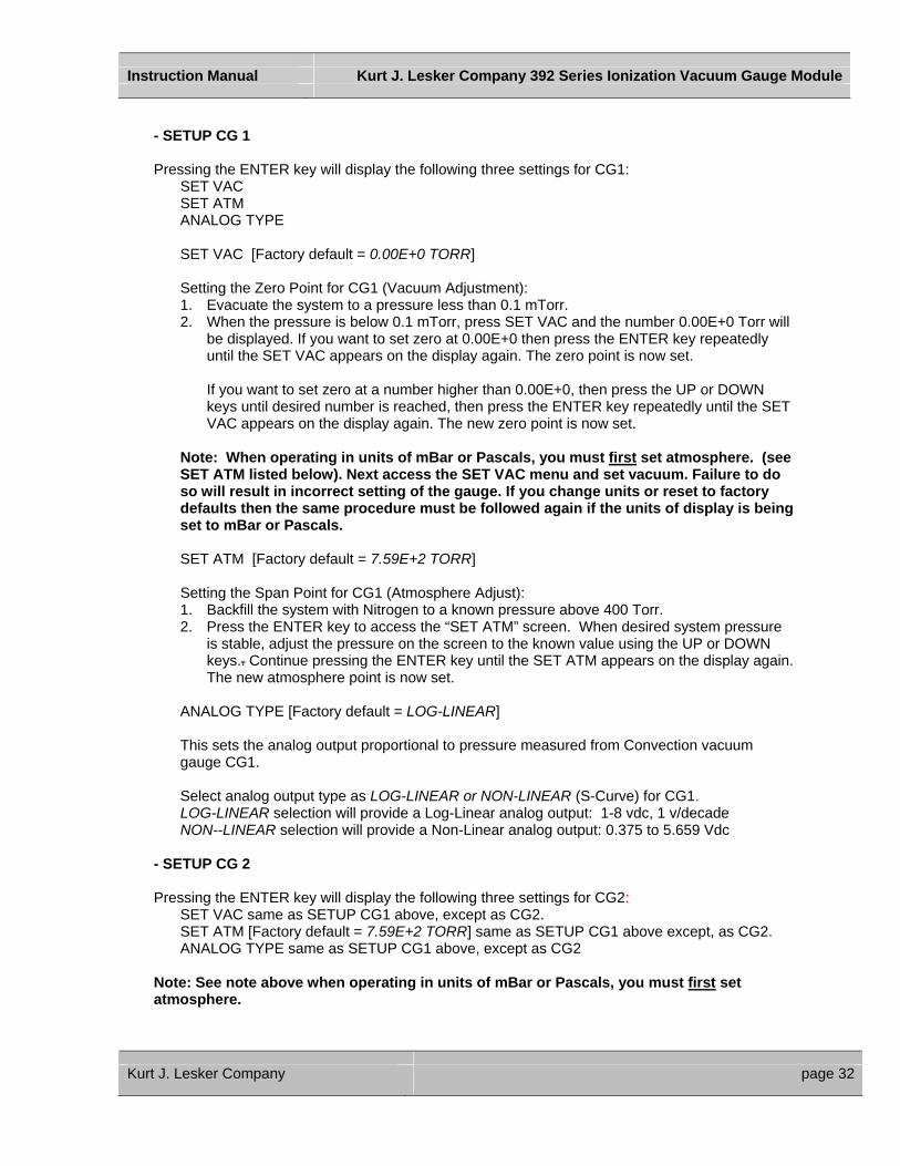
- SETUP CG 1 Pressing the ENTER key will display the following three settings for CG1: SET VAC SET ATM ANALOG TYPE
SET VAC [Factory default = 0.00E+0 TORR] Setting the Zero Point for CG1 (Vacuum Adjustment): 1. Evacuate the system to a pressure less than 0.1 mTorr. 2. When the pressure is below 0.1 mTorr, press SET VAC and the number 0.00E+0 Torr will
be displayed. If you want to set zero at 0.00E+0 then press the ENTER key repeatedly until the SET VAC appears on the display again. The zero point is now set.
If you want to set zero at a number higher than 0.00E+0, then press the UP or DOWN
keys until desired number is reached, then press the ENTER key repeatedly until the SET VAC appears on the display again. The new zero point is now set.
Note: When operating in units of mBar or Pascals, you must first set atmosphere. (see SET ATM listed below). Next access the SET VAC menu and set vacuum. Failure to do so will result in incorrect setting of the gauge. If you change units or reset to factory defaults then the same procedure must be followed again if the units of display is being set to mBar or Pascals.
SET ATM [Factory default = 7.59E+2 TORR] Setting the Span Point for CG1 (Atmosphere Adjust): 1. Backfill the system with Nitrogen to a known pressure above 400 Torr. 2. Press the ENTER key to access the “SET ATM” screen. When desired system pressure
is stable, adjust the pressure on the screen to the known value using the UP or DOWN keys.. Continue pressing the ENTER key until the SET ATM appears on the display again. The new atmosphere point is now set.
ANALOG TYPE [Factory default = LOG-LINEAR] This sets the analog output proportional to pressure measured from Convection vacuum gauge CG1. Select analog output type as LOG-LINEAR or NON-LINEAR (S-Curve) for CG1. LOG-LINEAR selection will provide a Log-Linear analog output: 1-8 vdc, 1 v/decade NON--LINEAR selection will provide a Non-Linear analog output: 0.375 to 5.659 Vdc
- SETUP CG 2
Pressing the ENTER key will display the following three settings for CG2: SET VAC same as SETUP CG1 above, except as CG2. SET ATM [Factory default = 7.59E+2 TORR] same as SETUP CG1 above except, as CG2. ANALOG TYPE same as SETUP CG1 above, except as CG2
Note: See note above when operating in units of mBar or Pascals, you must first set atmosphere.
Kurt J. Lesker Company page 32
Instruction Manual Kurt J. Lesker Company 392 Series Ionization Vacuum Gauge Module
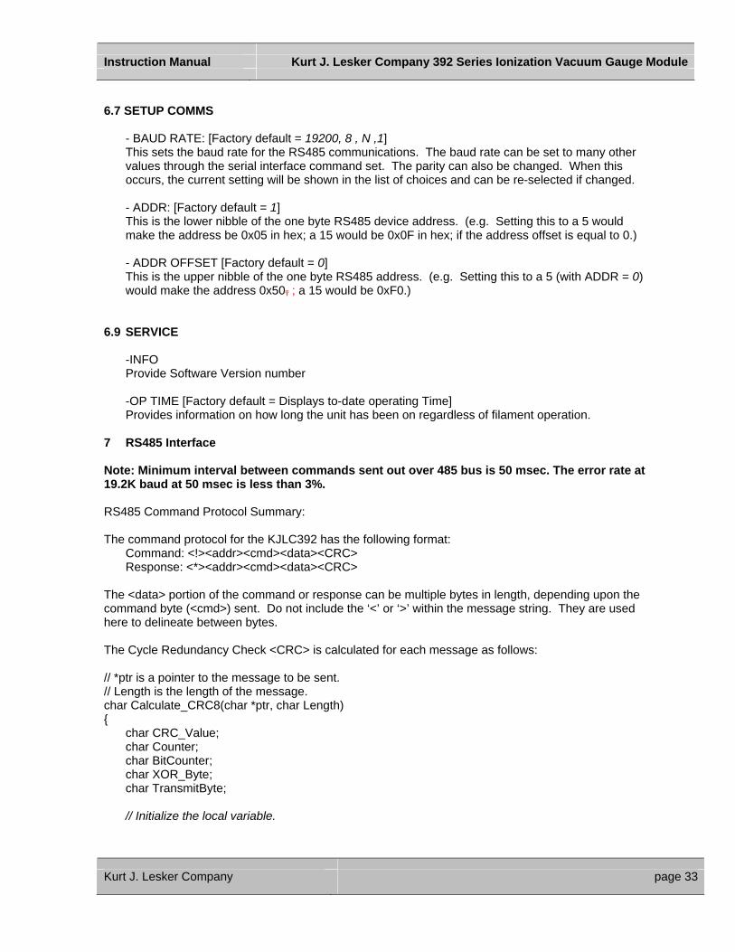
6.7 SETUP COMMS - BAUD RATE: [Factory default = 19200, 8 , N ,1]
This sets the baud rate for the RS485 communications. The baud rate can be set to many other values through the serial interface command set. The parity can also be changed. When this occurs, the current setting will be shown in the list of choices and can be re-selected if changed.
- ADDR: [Factory default = 1] This is the lower nibble of the one byte RS485 device address. (e.g. Setting this to a 5 would make the address be 0x05 in hex; a 15 would be 0x0F in hex; if the address offset is equal to 0.)
- ADDR OFFSET [Factory default = 0] This is the upper nibble of the one byte RS485 address. (e.g. Setting this to a 5 (with ADDR = 0) would make the address 0x50, ; a 15 would be 0xF0.)
6.9 SERVICE
-INFO Provide Software Version number
-OP TIME [Factory default = Displays to-date operating Time] Provides information on how long the unit has been on regardless of filament operation.
7 RS485 Interface Note: Minimum interval between commands sent out over 485 bus is 50 msec. The error rate at 19.2K baud at 50 msec is less than 3%. RS485 Command Protocol Summary: The command protocol for the KJLC392 has the following format: Command: <!><addr><cmd><data><CRC> Response: <*><addr><cmd><data><CRC> The <data> portion of the command or response can be multiple bytes in length, depending upon the command byte (<cmd>) sent. Do not include the ‘<’ or ‘>’ within the message string. They are used here to delineate between bytes. The Cycle Redundancy Check <CRC> is calculated for each message as follows: // *ptr is a pointer to the message to be sent. // Length is the length of the message. char Calculate_CRC8(char *ptr, char Length) { char CRC_Value; char Counter; char BitCounter; char XOR_Byte; char TransmitByte; // Initialize the local variable.
Kurt J. Lesker Company page 33
Instruction Manual Kurt J. Lesker Company 392 Series Ionization Vacuum Gauge Module
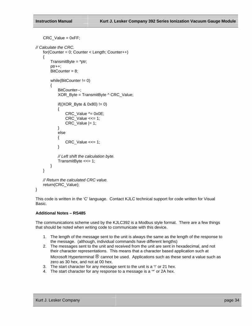
CRC_Value = 0xFF; // Calculate the CRC. for(Counter = 0; Counter < Length; Counter++) { TransmitByte = *ptr; ptr++; BitCounter = 8; while(BitCounter != 0) { BitCounter--; XOR_Byte = TransmitByte ^ CRC_Value; if((XOR_Byte & 0x80) != 0) { CRC_Value ^= 0x0E; CRC_Value <<= 1; CRC_Value |= 1; } else { CRC_Value <<= 1; } // Left shift the calculation byte. TransmitByte <<= 1; } } // Return the calculated CRC value. return(CRC_Value); } This code is written in the ‘C’ language. Contact KJLC technical support for code written for Visual Basic. Additional Notes – RS485 The communications scheme used by the KJLC392 is a Modbus style format. There are a few things that should be noted when writing code to communicate with this device.
1. The length of the message sent to the unit is always the same as the length of the response to the message. (although, individual commands have different lengths)
2. The messages sent to the unit and received from the unit are sent in hexadecimal, and not their character representations. This means that a character based application such at Microsoft Hyperterminal ® cannot be used. Applications such as these send a value such as zero as 30 hex, and not at 00 hex.
3. The start character for any message sent to the unit is a ‘!’ or 21 hex. 4. The start character for any response to a message is a ‘*’ or 2A hex.
Kurt J. Lesker Company page 34

Instruction Manual Kurt J. Lesker Company 392 Series Ionization Vacuum Gauge Module
5. The data part of the message sent to the unit does not matter. This portion of the message is ignored by the receiving unit. It is recommended that these bytes be set to zero prior to sending the message to the unit.
6. The data part of the responses are NOT ASCII characters. These are actual variable values that are of type char, float, or long. This shortens the messages and simplifies the code written by the customer by not having to convert from ASCII characters to typed values and back again.
7. The Cyclic Redundancy Check (CRC) is calculated using the routine shown in the RS485 Interface paragraph of the user manual. The length of the message is the number of bytes beginning at the “start” character, ending with the last byte of the data, and does not include the byte that will contain the CRC.
Example of actual data bytes sent and received for a ‘READ IG PRESSURE ONLY’ command: (This is done with the filament off) SENT: Byte 0: ‘!’ (0x21) (start character) Byte 1: 1 (0x01) (address) Byte 2: 2 (0x02) (command byte for READ IG PRESSURE) Byte 3: 0 (0x00) (don’t care units) Byte 4: 0 (0x00) (don’t care data 1) Byte 5: 0 (0x00) (don’t care data 2) Byte 6: 0 (0x00) (don’t care data 3) Byte 7: 0 (0x00) (don’t care data 4) Byte 8: 183 (0xB7) (CRC) RECEIVED: Byte 0: ‘*’ (0x2A) (start character) Byte 1: 1 (0x01) (address) Byte 2: 2 (0x02) (command byte for READ IG PRESSURE) Byte 3: 0 (0x00) (units; 0=Torr, 1= PASCALS, 2=mBAR) Byte 4: 0 (0x00) (floating point byte 1) Byte 5: 0 (0x00) (floating point byte 2) Byte 6: 0 (0x00) (floating point byte 3) Byte 7: 0 (0x00) (floating point byte 4) Byte 8: 148 (0x94) (CRC)
Kurt J. Lesker Company page 35
Instruction Manual Kurt J. Lesker Company 392 Series Ionization Vacuum Gauge Module
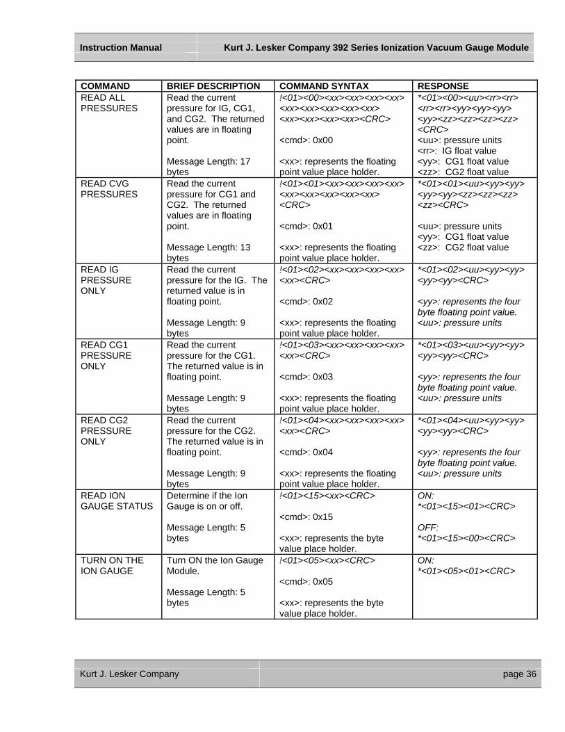
COMMAND BRIEF DESCRIPTION COMMAND SYNTAX RESPONSE READ ALL PRESSURES
Read the current pressure for IG, CG1, and CG2. The returned values are in floating point. Message Length: 17 bytes
!<01><00><xx><xx><xx><xx> <xx><xx><xx><xx><xx> <xx><xx><xx><xx><CRC> <cmd>: 0x00 <xx>: represents the floating point value place holder.
*<01><00><uu><rr><rr> <rr><rr><yy><yy><yy> <yy><zz><zz><zz><zz> <CRC> <uu>: pressure units <rr>: IG float value <yy>: CG1 float value <zz>: CG2 float value
READ CVG PRESSURES
Read the current pressure for CG1 and CG2. The returned values are in floating point. Message Length: 13 bytes
!<01><01><xx><xx><xx><xx> <xx><xx><xx><xx><xx> <CRC> <cmd>: 0x01 <xx>: represents the floating point value place holder.
*<01><01><uu><yy><yy> <yy><yy><zz><zz><zz> <zz><CRC> <uu>: pressure units <yy>: CG1 float value <zz>: CG2 float value
READ IG PRESSURE ONLY
Read the current pressure for the IG. The returned value is in floating point. Message Length: 9 bytes
!<01><02><xx><xx><xx><xx> <xx><CRC> <cmd>: 0x02 <xx>: represents the floating point value place holder.
*<01><02><uu><yy><yy> <yy><yy><CRC> <yy>: represents the four byte floating point value. <uu>: pressure units
READ CG1 PRESSURE ONLY
Read the current pressure for the CG1. The returned value is in floating point. Message Length: 9 bytes
!<01><03><xx><xx><xx><xx> <xx><CRC> <cmd>: 0x03 <xx>: represents the floating point value place holder.
*<01><03><uu><yy><yy> <yy><yy><CRC> <yy>: represents the four byte floating point value. <uu>: pressure units
READ CG2 PRESSURE ONLY
Read the current pressure for the CG2. The returned value is in floating point. Message Length: 9 bytes
!<01><04><xx><xx><xx><xx> <xx><CRC> <cmd>: 0x04 <xx>: represents the floating point value place holder.
*<01><04><uu><yy><yy> <yy><yy><CRC> <yy>: represents the four byte floating point value. <uu>: pressure units
READ ION GAUGE STATUS
Determine if the Ion Gauge is on or off. Message Length: 5 bytes
!<01><15><xx><CRC> <cmd>: 0x15 <xx>: represents the byte value place holder.
ON: *<01><15><01><CRC> OFF: *<01><15><00><CRC>
TURN ON THE ION GAUGE
Turn ON the Ion Gauge Module. Message Length: 5 bytes
!<01><05><xx><CRC> <cmd>: 0x05 <xx>: represents the byte value place holder.
ON: *<01><05><01><CRC>
Kurt J. Lesker Company page 36
Instruction Manual Kurt J. Lesker Company 392 Series Ionization Vacuum Gauge Module
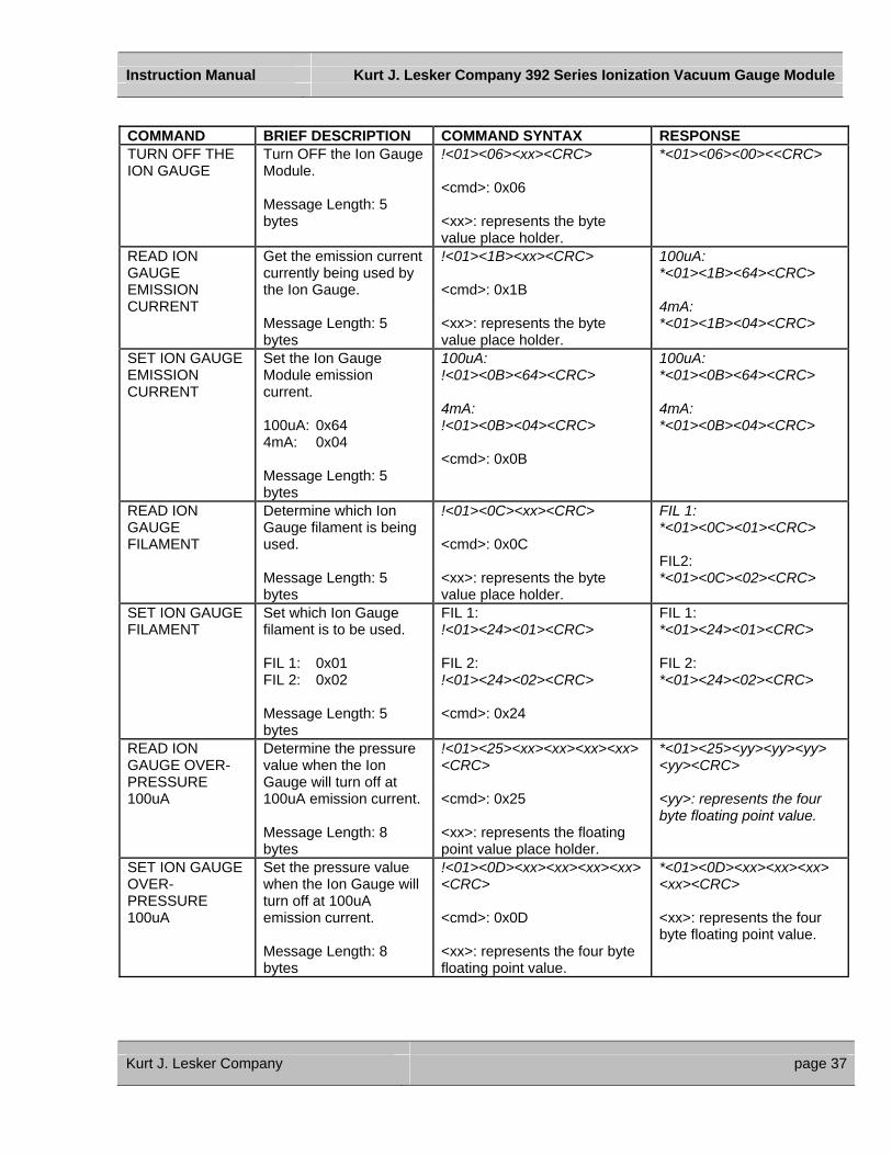
COMMAND BRIEF DESCRIPTION COMMAND SYNTAX RESPONSE TURN OFF THE ION GAUGE
Turn OFF the Ion Gauge Module. Message Length: 5 bytes
!<01><06><xx><CRC> <cmd>: 0x06 <xx>: represents the byte value place holder.
*<01><06><00><<CRC>
READ ION GAUGE EMISSION CURRENT
Get the emission current currently being used by the Ion Gauge. Message Length: 5 bytes
!<01><1B><xx><CRC> <cmd>: 0x1B <xx>: represents the byte value place holder.
100uA: *<01><1B><64><CRC> 4mA: *<01><1B><04><CRC>
SET ION GAUGE EMISSION CURRENT
Set the Ion Gauge Module emission current. 100uA: 0x64 4mA: 0x04 Message Length: 5 bytes
100uA: !<01><0B><64><CRC> 4mA: !<01><0B><04><CRC> <cmd>: 0x0B
100uA: *<01><0B><64><CRC> 4mA: *<01><0B><04><CRC>
READ ION GAUGE FILAMENT
Determine which Ion Gauge filament is being used. Message Length: 5 bytes
!<01><0C><xx><CRC> <cmd>: 0x0C <xx>: represents the byte value place holder.
FIL 1: *<01><0C><01><CRC> FIL2: *<01><0C><02><CRC>
SET ION GAUGE FILAMENT
Set which Ion Gauge filament is to be used. FIL 1: 0x01 FIL 2: 0x02 Message Length: 5 bytes
FIL 1: !<01><24><01><CRC> FIL 2: !<01><24><02><CRC> <cmd>: 0x24
FIL 1: *<01><24><01><CRC> FIL 2: *<01><24><02><CRC>
READ ION GAUGE OVER-PRESSURE 100uA
Determine the pressure value when the Ion Gauge will turn off at 100uA emission current. Message Length: 8 bytes
!<01><25><xx><xx><xx><xx><CRC> <cmd>: 0x25 <xx>: represents the floating point value place holder.
*<01><25><yy><yy><yy> <yy><CRC> <yy>: represents the four byte floating point value.
SET ION GAUGE OVER-PRESSURE 100uA
Set the pressure value when the Ion Gauge will turn off at 100uA emission current. Message Length: 8 bytes
!<01><0D><xx><xx><xx><xx><CRC> <cmd>: 0x0D <xx>: represents the four byte floating point value.
*<01><0D><xx><xx><xx> <xx><CRC> <xx>: represents the four byte floating point value.
Kurt J. Lesker Company page 37
Instruction Manual Kurt J. Lesker Company 392 Series Ionization Vacuum Gauge Module
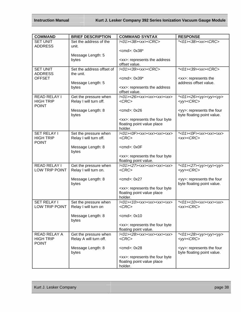
COMMAND BRIEF DESCRIPTION COMMAND SYNTAX RESPONSE SET UNIT ADDRESS
Set the address of the unit. Message Length: 5 bytes
!<01><38><xx><CRC> <cmd>: 0x38* <xx>: represents the address offset value.
*<01><38><xx><CRC>
SET UNIT ADDRESS OFFSET
Set the address offset of the unit. Message Length: 5 bytes
!<01><39><xx><CRC> <cmd>: 0x39* <xx>: represents the address offset value.
*<01><39><xx><CRC> <xx>: represents the address offset value.
READ RELAY I HIGH TRIP POINT
Get the pressure when Relay I will turn off. Message Length: 8 bytes
!<01><26><xx><xx><xx><xx><CRC> <cmd>: 0x26 <xx>: represents the four byte floating point value place holder.
*<01><26><yy><yy><yy> <yy><CRC> <yy>: represents the four byte floating point value.
SET RELAY I HIGH TRIP POINT
Set the pressure when Relay I will turn off. Message Length: 8 bytes
!<01><0F><xx><xx><xx><xx><CRC> <cmd>: 0x0F <xx>: represents the four byte floating point value.
*<01><0F><xx><xx><xx> <xx><CRC>
READ RELAY I LOW TRIP POINT
Get the pressure when Relay I will turn on. Message Length: 8 bytes
!<01><27><xx><xx><xx><xx><CRC> <cmd>: 0x27 <xx>: represents the four byte floating point value place holder.
*<01><27><yy><yy><yy> <yy><CRC> <yy>: represents the four byte floating point value.
SET RELAY I LOW TRIP POINT
Set the pressure when Relay I will turn on Message Length: 8 bytes
!<01><10><xx><xx><xx><xx><CRC> <cmd>: 0x10 <xx>: represents the four byte floating point value.
*<01><10><xx><xx><xx> <xx><CRC>
READ RELAY A HIGH TRIP POINT
Get the pressure when Relay A will turn off. Message Length: 8 bytes
!<01><28><xx><xx><xx><xx><CRC> <cmd>: 0x28 <xx>: represents the four byte floating point value place holder.
*<01><28><yy><yy><yy> <yy><CRC> <yy>: represents the four byte floating point value.
Kurt J. Lesker Company page 38

Instruction Manual Kurt J. Lesker Company 392 Series Ionization Vacuum Gauge Module
COMMAND BRIEF DESCRIPTION COMMAND SYNTAX RESPONSE SET RELAY A HIGH TRIP POINT
Set the pressure when Relay A will turn off. Message Length: 8 bytes
!<01><11><xx><xx><xx><xx><CRC> <cmd>: 0x11 <xx>: represents the four byte floating point value.
*<01><11><xx><xx><xx> <xx><CRC>
READ RELAY A LOW TRIP POINT
Get the pressure when Relay A will turn on. Message Length: 8 bytes
!<01><29><xx><xx><xx><xx><CRC> <cmd>: 0x29 <xx>: represents the four byte floating point value place holder.
*<01><29><yy><yy><yy> <yy><CRC> <yy>: represents the four byte floating point value.
SET RELAY A LOW TRIP POINT
Set the pressure when Relay A will turn on. Message Length: 8 bytes
!<01><12><xx><xx><xx><xx><CRC> <cmd>: 0x12 <xx>: represents the four byte floating point value.
*<01><12><xx><xx><xx> <xx><CRC>
READ RELAY B HIGH TRIP POINT
Get the pressure when Relay B will turn off. Message Length: 8 bytes
!<01><2A><xx><xx><xx><xx><CRC> <cmd>: 0x2A <xx>: represents the four byte floating point value place holder.
*<01><2A><yy><yy><yy> <yy><CRC> <yy>: represents the four byte floating point value.
SET RELAY B HIGH TRIP POINT
Set the pressure when Relay B will turn off. Message Length: 8 bytes
!<01><13><xx><xx><xx><xx><CRC> <cmd>: 0x13 <xx>: represents the four byte floating point value.
*<01><13><xx><xx><xx> <xx><CRC>
READ RELAY B LOW TRIP POINT
Get the pressure when Relay B will turn on. Message Length: 8 bytes
!<01><2B><xx><xx><xx><xx><CRC> <cmd>: 0x2B <xx>: represents the four byte floating point value place holder.
*<01><2B><yy><yy><yy> <yy><CRC> <yy>: represents the four byte floating point value.
SET RELAY B LOW TRIP POINT
Set the pressure when Relay B will turn on. Message Length: 8 bytes
!<01><14><xx><xx><xx><xx><CRC> <cmd>: 0x14 <xx>: represents the four byte floating point value.
*<01><14><xx><xx><xx> <xx><CRC>
Kurt J. Lesker Company page 39
Instruction Manual Kurt J. Lesker Company 392 Series Ionization Vacuum Gauge Module
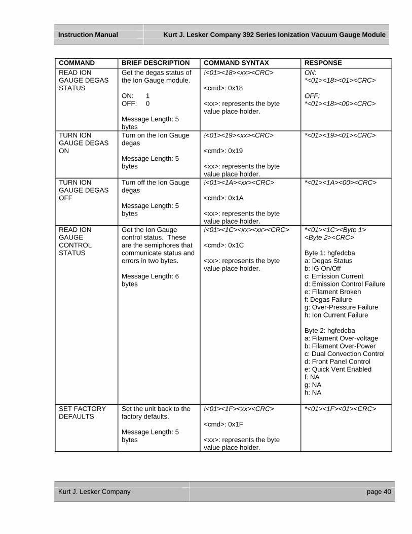
COMMAND BRIEF DESCRIPTION COMMAND SYNTAX RESPONSE READ ION GAUGE DEGAS STATUS
Get the degas status of the Ion Gauge module. ON: 1 OFF: 0 Message Length: 5 bytes
!<01><18><xx><CRC> <cmd>: 0x18 <xx>: represents the byte value place holder.
ON: *<01><18><01><CRC> OFF: *<01><18><00><CRC>
TURN ION GAUGE DEGAS ON
Turn on the Ion Gauge degas Message Length: 5 bytes
!<01><19><xx><CRC> <cmd>: 0x19 <xx>: represents the byte value place holder.
*<01><19><01><CRC>
TURN ION GAUGE DEGAS OFF
Turn off the Ion Gauge degas Message Length: 5 bytes
!<01><1A><xx><CRC> <cmd>: 0x1A <xx>: represents the byte value place holder.
*<01><1A><00><CRC>
READ ION GAUGE CONTROL STATUS
Get the Ion Gauge control status. These are the semiphores that communicate status and errors in two bytes. Message Length: 6 bytes
!<01><1C><xx><xx><CRC> <cmd>: 0x1C <xx>: represents the byte value place holder.
*<01><1C><Byte 1> <Byte 2><CRC> Byte 1: hgfedcba a: Degas Status b: IG On/Off c: Emission Current d: Emission Control Failure e: Filament Broken f: Degas Failure g: Over-Pressure Failure h: Ion Current Failure Byte 2: hgfedcba a: Filament Over-voltage b: Filament Over-Power c: Dual Convection Control d: Front Panel Control e: Quick Vent Enabled f: NA g: NA h: NA
SET FACTORY DEFAULTS
Set the unit back to the factory defaults. Message Length: 5 bytes
!<01><1F><xx><CRC> <cmd>: 0x1F <xx>: represents the byte value place holder.
*<01><1F><01><CRC>
Kurt J. Lesker Company page 40

Instruction Manual Kurt J. Lesker Company 392 Series Ionization Vacuum Gauge Module
COMMAND BRIEF DESCRIPTION COMMAND SYNTAX RESPONSE
SET COMMS BAUD RATE
Set the communications baud rate for the unit. Message Length: 5 bytes
!<01><20><xx><CRC> <cmd>: 0x20* <xx>: represents the byte value as follows: 00: 300 01: 600 02: 1200 03: 2400 04: 4800 05: 9600 06: 14,400 07: 19,200 08: 28,800 09: 38,400 0A: 57,600
*<01><20><xx><CRC>
RESET UNIT Reset the unit as if power has been cycled from off to on. Message Length: 5 bytes
!<01><22><xx><CRC> <cmd>: 0x22 <xx>: represents the byte
No response from unit.
READ CG1 VACUUM SETTING VALUE
Gets the CG1 vacuum pressure setting. Message Length: 8 bytes
!<01><2D><xx><xx><xx><xx><CRC> <cmd>: 0x2D <xx>: represents the four byte floating point value place holder.
*<01><2D><yy><yy><yy> <yy><CRC> <yy>: represents the four byte floating point value.
SET CG1 VACUUM SETTING VALUE
Sets the CG1 vacuum pressure setting. Message Length: 8 bytes
!<01><2C><xx><xx><xx><xx><CRC> <cmd>: 0x2C <xx>: represents the four byte floating point value.
*<01><2C><xx><xx><xx> <xx><CRC>
READ CG2 VACUUM SETTING VALUE
Gets the CG2 vacuum pressure setting. Message Length: 8 bytes
!<01><2F><xx><xx><xx><xx><CRC> <cmd>: 0x2F <xx>: represents the four byte floating point value place holder.
*<01><2F><yy><yy><yy> <yy><CRC> <yy>: represents the four byte floating point value.
Kurt J. Lesker Company page 41

Instruction Manual Kurt J. Lesker Company 392 Series Ionization Vacuum Gauge Module
COMMAND BRIEF DESCRIPTION COMMAND SYNTAX RESPONSE
SET CG2 VACUUM SETTING VALUE
Sets the CG2 vacuum pressure setting. Message Length: 8 bytes
!<01><2E><xx><xx><xx><xx><CRC> <cmd>: 0x2E <xx>: represents the four byte floating point value.
*<01><2E><xx><xx><xx> <xx><CRC>
READ CG1 ATMOSPHERE SETTING VALUE
Gets the CG1 atmosphere pressure setting. Message Length: 8 bytes
!<01><31><xx><xx><xx><xx><CRC> <cmd>: 0x31 <xx>: represents the four byte floating point value place holder.
*<01><31><yy><yy><yy> <yy><CRC> <xyyx>: represents the four byte floating point value.
SET CG1 ATMOSPHERE SETTING VALUE
Sets the CG1 atmosphere pressure setting. Message Length: 8 bytes
!<01><30><xx><xx><xx><xx><CRC> <cmd>: 0x30 <xx>: represents the four byte floating point value.
*<01><30><xx><xx><xx> <xx><CRC>
READ CG2 ATMOSPHERE SETTING VALUE
Gets the CG2 atmosphere pressure setting. Message Length: 8 bytes
!<01><33><xx><xx><xx><xx><CRC> <cmd>: 0x33 <xx>: represents the four byte floating point value place holder.
*<01><33><yy><yy><yy> <yy><CRC> <xyyx>: represents the four byte floating point value.
SET CG2 ATMOSPHERE SETTING VALUE
Sets the CG2 atmosphere pressure setting. Message Length: 8 bytes
!<01><32><xx><xx><xx><xx><CRC> <cmd>: 0x32 <xx>: represents the four byte floating point value.
*<01><32><xx><xx><xx> <xx><CRC>
READ CG1 ANALOG OUTPUT TYPE
Get the type of analog output setup for CG1 Message Length: 5 bytes
!<01><35><xx><CRC> <cmd>: 0x35 <xx>: represents the byte value place holder.
*<01><35><xx><CRC> <yy>: represents the byte value as follows: 00: Non-Linear 01: Log-Linear
Kurt J. Lesker Company page 42
Instruction Manual Kurt J. Lesker Company 392 Series Ionization Vacuum Gauge Module
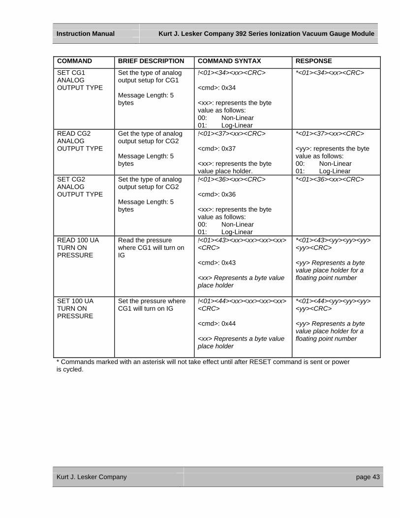
COMMAND BRIEF DESCRIPTION COMMAND SYNTAX RESPONSE
SET CG1 ANALOG OUTPUT TYPE
Set the type of analog output setup for CG1 Message Length: 5 bytes
!<01><34><xx><CRC> <cmd>: 0x34 <xx>: represents the byte value as follows: 00: Non-Linear 01: Log-Linear
*<01><34><xx><CRC>
READ CG2 ANALOG OUTPUT TYPE
Get the type of analog output setup for CG2 Message Length: 5 bytes
!<01><37><xx><CRC> <cmd>: 0x37 <xx>: represents the byte value place holder.
*<01><37><xx><CRC> <yy>: represents the byte value as follows: 00: Non-Linear 01: Log-Linear
SET CG2 ANALOG OUTPUT TYPE
Set the type of analog output setup for CG2 Message Length: 5 bytes
!<01><36><xx><CRC> <cmd>: 0x36 <xx>: represents the byte value as follows: 00: Non-Linear 01: Log-Linear
*<01><36><xx><CRC>
READ 100 UA TURN ON PRESSURE
Read the pressure where CG1 will turn on IG
!<01><43><xx><xx><xx><xx> <CRC> <cmd>: 0x43 <xx> Represents a byte value place holder
*<01><43><yy><yy><yy> <yy><CRC> <yy> Represents a byte value place holder for a floating point number
SET 100 UA TURN ON PRESSURE
Set the pressure where CG1 will turn on IG
!<01><44><xx><xx><xx><xx> <CRC> <cmd>: 0x44 <xx> Represents a byte value place holder
*<01><44><yy><yy><yy> <yy><CRC> <yy> Represents a byte value place holder for a floating point number
* Commands marked with an asterisk will not take effect until after RESET command is sent or power is cycled.
Kurt J. Lesker Company page 43
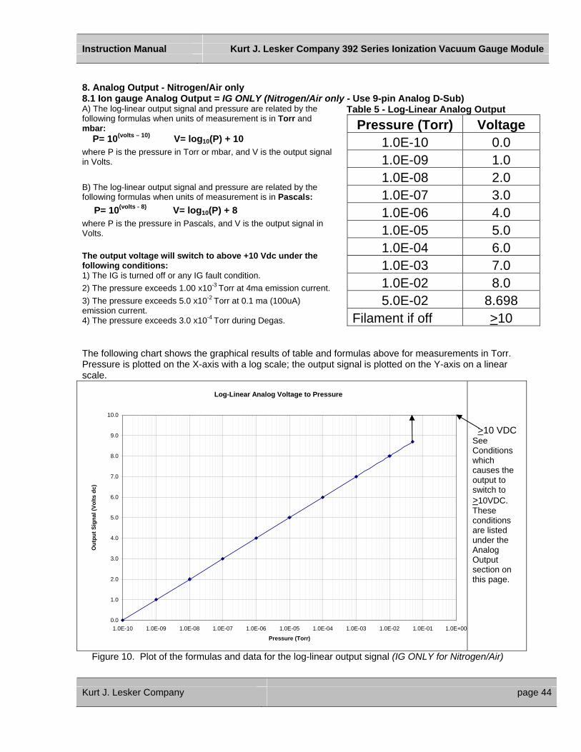
Instruction Manual Kurt J. Lesker Company 392 Series Ionization Vacuum Gauge Module
8. Analog Output - Nitrogen/Air only 8.1 Ion gauge Analog Output = IG ONLY (Nitrogen/Air only - Use 9-pin Analog D-Sub) A) The log-linear output signal and pressure are related by the following formulas when units of measurement is in Torr and mbar: P= 10(volts – 10) V= log10(P) + 10 where P is the pressure in Torr or mbar, and V is the output signal in Volts. B) The log-linear output signal and pressure are related by the following formulas when units of measurement is in Pascals: P= 10(volts - 8) V= log10(P) + 8 where P is the pressure in Pascals, and V is the output signal in Volts. The output voltage will switch to above +10 Vdc under the following conditions: 1) The IG is turned off or any IG fault condition. 2) The pressure exceeds 1.00 x10⁻³ Torr at 4ma emission current. 3) The pressure exceeds 5.0 x10⁻² Torr at 0.1 ma (100uA) emission current. 4) The pressure exceeds 3.0 x10⁻⁴ Torr during Degas.
Table 5 - Log-Linear Analog Output
Pressure (Torr) Voltage 1.0E-10 0.0 1.0E-09 1.0 1.0E-08 2.0 1.0E-07 3.0 1.0E-06 4.0 1.0E-05 5.0 1.0E-04 6.0 1.0E-03 7.0 1.0E-02 8.0 5.0E-02 8.698
Filament if off >10
The following chart shows the graphical results of table and formulas above for measurements in Torr. Pressure is plotted on the X-axis with a log scale; the output signal is plotted on the Y-axis on a linear scale.
Log-Linear Analog Voltage to Pressure
0.0
1.0
2.0
3.0
4.0
5.0
6.0
7.0
8.0
9.0
10.0
1.0E-10 1.0E-09 1.0E-08 1.0E-07 1.0E-06 1.0E-05 1.0E-04 1.0E-03 1.0E-02 1.0E-01 1.0E+00
Pressure (Torr)
Out
put S
igna
l (Vo
lts d
c)
>10 VDC See Conditions which causes the output to switch to >10VDC. These conditions are listed under the Analog Output section on this page.
Figure 10. Plot of the formulas and data for the log-linear output signal (IG ONLY for Nitrogen/Air)
Kurt J. Lesker Company page 44
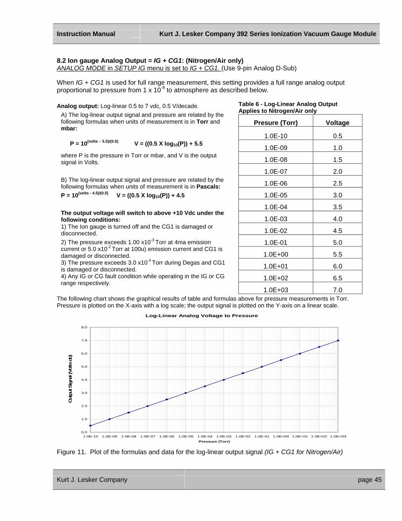
Instruction Manual Kurt J. Lesker Company 392 Series Ionization Vacuum Gauge Module
8.2 Ion gauge Analog Output = IG + CG1: (Nitrogen/Air only) ANALOG MODE in SETUP IG menu is set to IG + CG1. (Use 9-pin Analog D-Sub) When IG + CG1 is used for full range measurement, this setting provides a full range analog output proportional to pressure from 1 x 10⁻⁹ to atmosphere as described below. Analog output: Log-linear 0.5 to 7 vdc, 0.5 V/decade.
A) The log-linear output signal and pressure are related by the following formulas when units of measurement is in Torr and mbar:
P = 10(volts – 5.5)/(0.5) V = ((0.5 X log10(P)) + 5.5
where P is the pressure in Torr or mbar, and V is the output signal in Volts. B) The log-linear output signal and pressure are related by the following formulas when units of measurement is in Pascals: P = 10(volts - 4.5)/(0.5) V = ((0.5 X log10(P)) + 4.5 The output voltage will switch to above +10 Vdc under the following conditions: 1) The Ion gauge is turned off and the CG1 is damaged or disconnected. 2) The pressure exceeds 1.00 x10⁻³ Torr at 4ma emission current or 5.0 x10⁻² Torr at 100u) emission current and CG1 is damaged or disconnected. 3) The pressure exceeds 3.0 x10⁻⁴ Torr during Degas and CG1 is damaged or disconnected. 4) Any IG or CG fault condition while operating in the IG or CG range respectively.
Table 6 - Log-Linear Analog Output Applies to Nitrogen/Air only
Presure (Torr) Voltage
1.0E-10 0.5
1.0E-09 1.0
1.0E-08 1.5
1.0E-07 2.0
1.0E-06 2.5
1.0E-05 3.0
1.0E-04 3.5
1.0E-03 4.0
1.0E-02 4.5
1.0E-01 5.0
1.0E+00 5.5
1.0E+01 6.0
1.0E+02 6.5
1.0E+03 7.0 The following chart shows the graphical results of table and formulas above for pressure measurements in Torr. Pressure is plotted on the X-axis with a log scale; the output signal is plotted on the Y-axis on a linear scale.
Log-Linear Analog Voltage to Pressure
0.0
1.0
2.0
3.0
4.0
5.0
6.0
7.0
8.0
1.0E-10 1.0E-09 1.0E-08 1.0E-07 1.0E-06 1.0E-05 1.0E-04 1.0E-03 1.0E-02 1.0E-01 1.0E+00 1.0E+01 1.0E+02 1.0E+03
Pressure (Torr)
Out
put S
igna
l (Vo
lts d
c)
Figure 11. Plot of the formulas and data for the log-linear output signal (IG + CG1 for Nitrogen/Air)
Kurt J. Lesker Company page 45

Instruction Manual Kurt J. Lesker Company 392 Series Ionization Vacuum Gauge Module
8.3 Convection Gauge Analog Output = LOG-LINEAR: (Nitrogen / Air only) (Use CG1 and CG2 green terminal blocks) ANALOG TYPE in SETUP CG1 or SETUP CG2 sub menu of SETUP CGS menu is set to LOG-LINEAR. This setting provides a log-linear analog output for Convection Gauge 1 or 2 only. The analog output is proportional to pressure measurements from either of the convection gauges 1 or 2 as described below: Analog output: Log-linear 1.0 to 8 vdc, 1.0 V/decade.
A) The log-linear output signal and pressure are related by the following formulas when units of measurement is in Torr and mbar:
P = 10(volts – 5) V = log10(P) + 5 where P is the pressure in Torr or mbar, and V is the output signal in Volts. B) The log-linear output signal and pressure are related by the following formulas when units of measurement is in Pascals:
P = 10(volts – 3) V = log10(P) + 3 where P is the pressure in Pascals, and V is the output signal in Volts.
The following chart shows the graphical results of table and formulas above. For pressure measurements in Torr. Pressure is plotted on the X-axis with a log scale; the output signal is plotted on the Y-axis on a linear scale.
Log-Linear Analog Voltage to Pressure
0.000
1.000
2.000
3.000
4.000
5.000
6.000
7.000
8.000
9.000
1.0E-04 1.0E-03 1.0E-02 1.0E-01 1.0E+00 1.0E+01 1.0E+02 1.0E+03
Pressure (Torr)
Out
put S
igna
l (Vo
lts d
c)
Table 7 - Log-Linear Analog Applies to Nitrogen/Air only
Pressure (Torr) Voltage
1.0E-04 1.000 2.0E-04 1.301 5.0E-04 1.699 1.0E-03 2.000 2.0E-03 2.301 5.0E-03 2.699 1.0E-02 3.000 2.0E-02 3.301 5.0E-02 3.699 1.0E-01 4.000 2.0E-01 4.301 5.0E-01 4.699 1.0E+00 5.000 2.0E+00 5.301 5.0E+00 5.699 1.0E+01 6.000 2.0E+01 6.301 5.0E+01 6.699 1.0E+02 7.000 2.0E+02 7.301 3.0E+02 7.477 4.0E+02 7.602 5.0E+02 7.699 6.0E+02 7.778 7.0E+02 7.845 7.6E+02 7.881 8.0E+02 7.903 9.0E+02 7.954 1.0E+03 8.000
Figure 12. Plot of the formulas and data for the log-linear output signal (CG1 and CG2)
Kurt J. Lesker Company page 46

Instruction Manual Kurt J. Lesker Company 392 Series Ionization Vacuum Gauge Module
8.4 Convection Gauge Analog Output = NON-LINEAR: (Nitrogen/Air only) ANALOG TYPE in SETUP CG1 or SETUP CG2 sub menu of SETUP CGS menu is set to NON-LINEAR. Use CG1 and CG2 green terminal blocks) The non-linear S-curve is convenient if you are replacing a Convectron® which has that output, and you do not want to change anything in the control system. For new systems, however, the formulas needed to interpret the non-linear signal are complex and difficult to use. The linear or log-linear signal is generally easier to interface with today's data acquisition or control systems. Non-Linear Output Granville-Phillips' first Convectron® gauge controllers produced a non-linear output signal of 0.375 to 5.659 VDC for 0 to 1000 Torr of N2, roughly in the shape of an "S" curve, as shown at right. GP adopted the same output curve for most of their Mini-Convectron® modules and controllers with non-linear output (though in recent years, some GP controllers produced a different S-curve). The non-linear output from KJLC Convection gauges, modules, and controllers duplicates exactly the original S-curve of 0.375 to 5.659 VDC for 0 to 1000 Torr.
Table 8 – Non-Linear Analog Applies to Nitrogen/Air only
Pressure (Torr) Voltage
0.0000 0.37511.0E-04 0.37592.0E-04 0.37685.0E-04 0.37951.0E-03 0.38402.0E-03 0.39275.0E-03 0.41741.0E-02 0.45552.0E-02 0.52265.0E-02 0.68191.0E-01 0.87802.0E-01 1.15525.0E-01 1.68331.0E+00 2.21682.0E+00 2.84185.0E+00 3.67531.0E+01 4.20562.0E+01 4.57665.0E+01 4.84641.0E+02 4.94492.0E+02 5.01903.0E+02 5.11114.0E+02 5.22365.0E+02 5.32946.0E+02 5.41947.0E+02 5.49497.6E+02 5.53408.0E+02 5.55819.0E+02 5.61411.0E+03 5.6593
Non-Linear Analog Output
10+310-3 10-2 10-1 100 10+1 10+2
1
2
3
4
5
6
Pressure - Torr
Output - Volts
Non-Linear Analog Output
10+310-3 10-2 10-1 100 10+1 10+2
1
2
3
4
5
6
Pressure - Torr
Output - Volts
10+310-3 10-2 10-1 100 10+1 10+2
1
2
3
4
5
6
Pressure - Torr
Output - Volts
Figure 13. Plot of the formulas and data for the Non-linear output signal (CG1 and CG2)
Kurt J. Lesker Company page 47
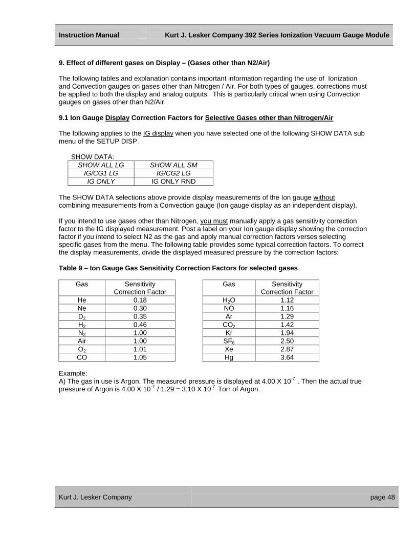
Instruction Manual Kurt J. Lesker Company 392 Series Ionization Vacuum Gauge Module
9. Effect of different gases on Display – (Gases other than N2/Air) The following tables and explanation contains important information regarding the use of Ionization and Convection gauges on gases other than Nitrogen / Air. For both types of gauges, corrections must be applied to both the display and analog outputs. This is particularly critical when using Convection gauges on gases other than N2/Air. 9.1 Ion Gauge Display Correction Factors for Selective Gases other than Nitrogen/Air The following applies to the IG display when you have selected one of the following SHOW DATA sub menu of the SETUP DISP.
SHOW DATA: SHOW ALL LG SHOW ALL SM
IG/CG1 LG IG/CG2 LG IG ONLY IG ONLY RND
The SHOW DATA selections above provide display measurements of the Ion gauge without combining measurements from a Convection gauge (Ion gauge display as an independent display). If you intend to use gases other than Nitrogen, you must manually apply a gas sensitivity correction factor to the IG displayed measurement. Post a label on your Ion gauge display showing the correction factor if you intend to select N2 as the gas and apply manual correction factors verses selecting specific gases from the menu. The following table provides some typical correction factors. To correct the display measurements, divide the displayed measured pressure by the correction factors: Table 9 – Ion Gauge Gas Sensitivity Correction Factors for selected gases
Gas Sensitivity Correction Factor
Gas Sensitivity Correction Factor
He 0.18 H2O 1.12 Ne 0.30 NO 1.16 D2 0.35 Ar 1.29 H2 0.46 CO2 1.42 N2 1.00 Kr 1.94 Air 1.00 SF6 2.50 O2 1.01 Xe 2.87 CO 1.05 Hg 3.64
Example: A) The gas in use is Argon. The measured pressure is displayed at 4.00 X 10⁻⁷ . Then the actual true pressure of Argon is 4.00 X 10⁻⁷ / 1.29 = 3.10 X 10⁻⁷ Torr of Argon.
Kurt J. Lesker Company page 48

Instruction Manual Kurt J. Lesker Company 392 Series Ionization Vacuum Gauge Module
9.2 Convection Gauge display conversion for Selective Gases other than Nitrogen/Air The following applies to the Convection Gauge display when you have selected one of the following SHOW DATA sub menu of the SETUP DISP. (Convection Gauges operating as independent gauges) SHOW DATA:
SHOW ALL LG SHOW ALL SM CG1 ONLY IG/CG1 LG IG/CG2 LG CG2 ONLY
CG1/CG2 LG CG1/CG2 SM Table 10 – Displayed Pressure Readings vs Pressure for selected gases – CG1 and CG2
OP= overpressure When using gases other than Nitrogen/Air you must use the above look-up table to determine true pressures of selected gases as measured by Convection gauges 1 & 2 (CG1 & CG2). Example If the gas is Ar, when the true pressure is 100 Torr, the CG display will read about 8.83 Torr. If you are backfilling your vacuum system with Ar, when your system reaches atmospheric pressure of 760 Torr true pressure, your gauge will be reading about 20 Torr. If you continue to backfill your system, attempting to increase the reading up to 760, you will overpressurize your chamber and probably blow up your vacuum system ! What this example illustrates is that, without proper precautions, use of different gases can result in injury to personnel and/or damage to equipment.
Kurt J. Lesker Company page 49
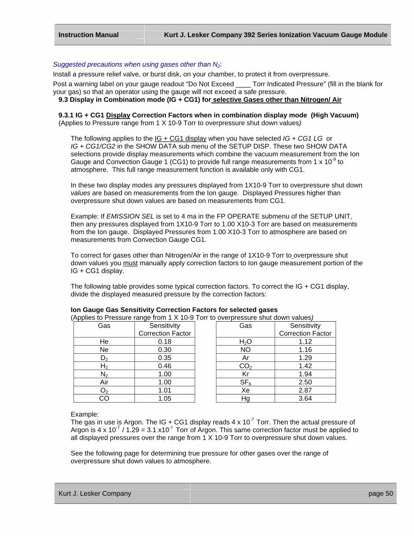
Instruction Manual Kurt J. Lesker Company 392 Series Ionization Vacuum Gauge Module
Suggested precautions when using gases other than N2: Install a pressure relief valve, or burst disk, on your chamber, to protect it from overpressure. Post a warning label on your gauge readout "Do Not Exceed ____ Torr Indicated Pressure" (fill in the blank for your gas) so that an operator using the gauge will not exceed a safe pressure.
9.3 Display in Combination mode (IG + CG1) for selective Gases other than Nitrogen/ Air 9.3.1 IG + CG1 Display Correction Factors when in combination display mode (High Vacuum) (Applies to Pressure range from 1 X 10⁻⁹ Torr to overpressure shut down values)
The following applies to the IG + CG1 display when you have selected IG + CG1 LG or IG + CG1/CG2 in the SHOW DATA sub menu of the SETUP DISP. These two SHOW DATA selections provide display measurements which combine the vacuum measurement from the Ion Gauge and Convection Gauge 1 (CG1) to provide full range measurements from 1 x 10⁻⁹ to atmosphere. This full range measurement function is available only with CG1.
In these two display modes any pressures displayed from 1X10⁻⁹ Torr to overpressure shut down values are based on measurements from the Ion gauge. Displayed Pressures higher than overpressure shut down values are based on measurements from CG1. Example: If EMISSION SEL is set to 4 ma in the FP OPERATE submenu of the SETUP UNIT, then any pressures displayed from 1X10⁻⁹ Torr to 1.00 X10⁻³ Torr are based on measurements from the Ion gauge. Displayed Pressures from 1.00 X10⁻³ Torr to atmosphere are based on measurements from Convection Gauge CG1. To correct for gases other than Nitrogen/Air in the range of 1X10⁻⁹ Torr to overpressure shut down values you must manually apply correction factors to Ion gauge measurement portion of the IG + CG1 display.
The following table provides some typical correction factors. To correct the IG + CG1 display, divide the displayed measured pressure by the correction factors:
Ion Gauge Gas Sensitivity Correction Factors for selected gases (Applies to Pressure range from 1 X 10⁻⁹ Torr to overpressure shut down values)
Gas Sensitivity Correction Factor
Gas Sensitivity Correction Factor
He 0.18 H2O 1.12 Ne 0.30 NO 1.16 D2 0.35 Ar 1.29 H2 0.46 CO2 1.42 N2 1.00 Kr 1.94 Air 1.00 SF6 2.50 O2 1.01 Xe 2.87 CO 1.05 Hg 3.64
Example: The gas in use is Argon. The IG + CG1 display reads 4 x 10⁻⁷ Torr. Then the actual pressure of Argon is 4 x 10⁻⁷ / 1.29 = 3.1 x10⁻⁷ Torr of Argon. This same correction factor must be applied to all displayed pressures over the range from 1 X 10⁻⁹ Torr to overpressure shut down values. See the following page for determining true pressure for other gases over the range of overpressure shut down values to atmosphere.
Kurt J. Lesker Company page 50
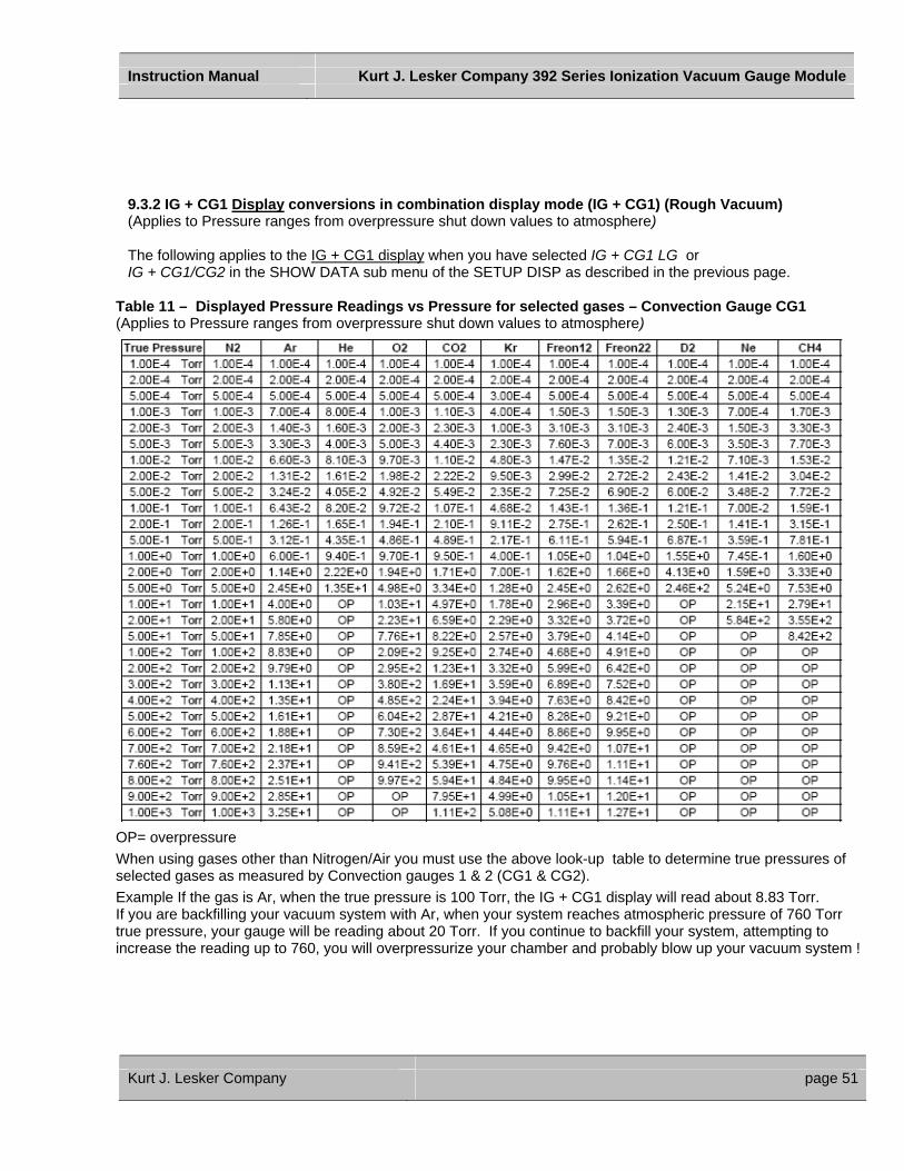
Instruction Manual Kurt J. Lesker Company 392 Series Ionization Vacuum Gauge Module
9.3.2 IG + CG1 Display conversions in combination display mode (IG + CG1) (Rough Vacuum) (Applies to Pressure ranges from overpressure shut down values to atmosphere) The following applies to the IG + CG1 display when you have selected IG + CG1 LG or IG + CG1/CG2 in the SHOW DATA sub menu of the SETUP DISP as described in the previous page.
Table 11 – Displayed Pressure Readings vs Pressure for selected gases – Convection Gauge CG1 (Applies to Pressure ranges from overpressure shut down values to atmosphere)
OP= overpressure When using gases other than Nitrogen/Air you must use the above look-up table to determine true pressures of selected gases as measured by Convection gauges 1 & 2 (CG1 & CG2). Example If the gas is Ar, when the true pressure is 100 Torr, the IG + CG1 display will read about 8.83 Torr. If you are backfilling your vacuum system with Ar, when your system reaches atmospheric pressure of 760 Torr true pressure, your gauge will be reading about 20 Torr. If you continue to backfill your system, attempting to increase the reading up to 760, you will overpressurize your chamber and probably blow up your vacuum system !
Kurt J. Lesker Company page 51
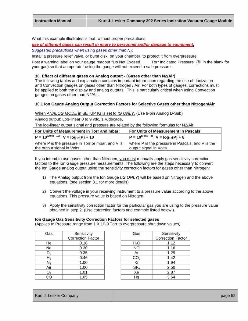
Instruction Manual Kurt J. Lesker Company 392 Series Ionization Vacuum Gauge Module
What this example illustrates is that, without proper precautions, use of different gases can result in injury to personnel and/or damage to equipment. Suggested precautions when using gases other than N2: Install a pressure relief valve, or burst disk, on your chamber, to protect it from overpressure. Post a warning label on your gauge readout "Do Not Exceed ____ Torr Indicated Pressure" (fill in the blank for your gas) so that an operator using the gauge will not exceed a safe pressure.
10. Effect of different gases on Analog output - (Gases other than N2/Air) The following tables and explanation contains important information regarding the use of Ionization and Convection gauges on gases other than Nitrogen / Air. For both types of gauges, corrections must be applied to both the display and analog outputs. This is particularly critical when using Convection gauges on gases other than N2/Air. 10.1 Ion Gauge Analog Output Correction Factors for Selective Gases other than Nitrogen/Air When ANALOG MODE in SETUP IG is set to IG ONLY. (Use 9-pin Analog D-Sub) Analog output: Log-linear 0 to 9 vdc, 1 V/decade. The log-linear output signal and pressure are related by the following formulas for N2/Air: For Units of Measurement in Torr and mbar: For Units of Measurement in Pascals: P = 10(volts - 10) V = log10(P) + 10 P = 10(volts - 8) V = log10(P) + 8 where P is the pressure in Torr or mbar, and V is the output signal in Volts.
where P is the pressure in Pascals, and V is the output signal in Volts.
If you intend to use gases other than Nitrogen, you must manually apply gas sensitivity correction factors to the Ion Gauge pressure measurements. The following are the steps necessary to convert the Ion Gauge analog output using the sensitivity correction factors for gases other than Nitrogen:
1) The Analog output from the Ion Gauge (IG ONLY) will be based on Nitrogen and the above equations. (see section 8.1 for more details)
2) Convert the voltage in your receiving instrument to a pressure value according to the above
equations. This pressure value is based on Nitrogen.
3) Apply the sensitivity correction factor for the particular gas you are using to the pressure value obtained in step 2. (Use correction factors and example listed below.).
Ion Gauge Gas Sensitivity Correction Factors for selected gases (Applies to Pressure range from 1 X 10⁻⁹ Torr to overpressure shut down values)
Gas Sensitivity Correction Factor
Gas Sensitivity Correction Factor
He 0.18 H2O 1.12 Ne 0.30 NO 1.16 D2 0.35 Ar 1.29 H2 0.46 CO2 1.42 N2 1.00 Kr 1.94 Air 1.00 SF6 2.50 O2 1.01 Xe 2.87 CO 1.05 Hg 3.64
Kurt J. Lesker Company page 52
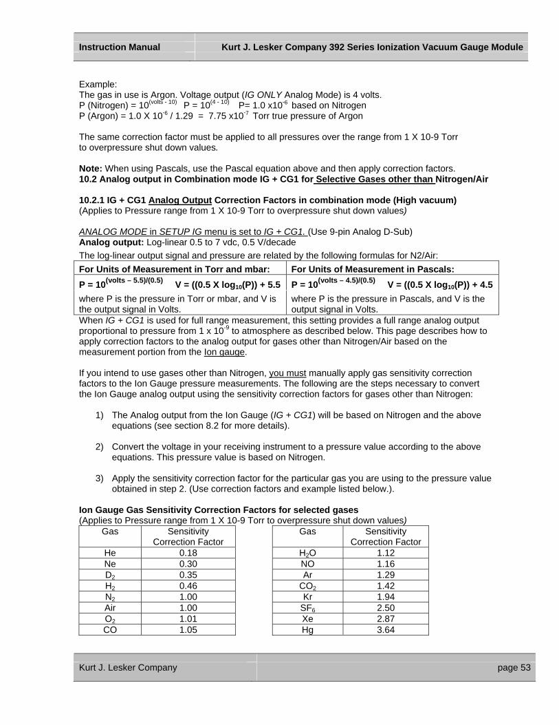
Instruction Manual Kurt J. Lesker Company 392 Series Ionization Vacuum Gauge Module
Example: The gas in use is Argon. Voltage output (IG ONLY Analog Mode) is 4 volts. P (Nitrogen) = 10(volts - 10) P = 10(4 - 10) P= 1.0 x10⁻⁶ based on Nitrogen P (Argon) = 1.0 X 10⁻⁶ / 1.29 = 7.75 x10⁻⁷ Torr true pressure of Argon The same correction factor must be applied to all pressures over the range from 1 X 10⁻⁹ Torr to overpressure shut down values. Note: When using Pascals, use the Pascal equation above and then apply correction factors. 10.2 Analog output in Combination mode IG + CG1 for Selective Gases other than Nitrogen/Air 10.2.1 IG + CG1 Analog Output Correction Factors in combination mode (High vacuum) (Applies to Pressure range from 1 X 10⁻⁹ Torr to overpressure shut down values) ANALOG MODE in SETUP IG menu is set to IG + CG1. (Use 9-pin Analog D-Sub) Analog output: Log-linear 0.5 to 7 vdc, 0.5 V/decade The log-linear output signal and pressure are related by the following formulas for N2/Air: For Units of Measurement in Torr and mbar: For Units of Measurement in Pascals: P = 10(volts – 5.5)/(0.5) V = ((0.5 X log10(P)) + 5.5 P = 10(volts – 4.5)/(0.5) V = ((0.5 X log10(P)) + 4.5 where P is the pressure in Torr or mbar, and V is the output signal in Volts.
where P is the pressure in Pascals, and V is the output signal in Volts.
When IG + CG1 is used for full range measurement, this setting provides a full range analog output proportional to pressure from 1 x 10⁻⁹ to atmosphere as described below. This page describes how to apply correction factors to the analog output for gases other than Nitrogen/Air based on the measurement portion from the Ion gauge. If you intend to use gases other than Nitrogen, you must manually apply gas sensitivity correction factors to the Ion Gauge pressure measurements. The following are the steps necessary to convert the Ion Gauge analog output using the sensitivity correction factors for gases other than Nitrogen:
1) The Analog output from the Ion Gauge (IG + CG1) will be based on Nitrogen and the above equations (see section 8.2 for more details).
2) Convert the voltage in your receiving instrument to a pressure value according to the above
equations. This pressure value is based on Nitrogen.
3) Apply the sensitivity correction factor for the particular gas you are using to the pressure value obtained in step 2. (Use correction factors and example listed below.).
Ion Gauge Gas Sensitivity Correction Factors for selected gases (Applies to Pressure range from 1 X 10⁻⁹ Torr to overpressure shut down values)
Gas Sensitivity Correction Factor
Gas Sensitivity Correction Factor
He 0.18 H2O 1.12 Ne 0.30 NO 1.16 D2 0.35 Ar 1.29 H2 0.46 CO2 1.42 N2 1.00 Kr 1.94 Air 1.00 SF6 2.50 O2 1.01 Xe 2.87 CO 1.05 Hg 3.64
Kurt J. Lesker Company page 53

Instruction Manual Kurt J. Lesker Company 392 Series Ionization Vacuum Gauge Module
Example: The gas in use is Argon. Voltage output (IG + CG1 Analog Mode) is 3 volts. P (Nitrogen) = 10(volts – 5.5)/(0.5) P = 10(3 – 5.5) / (0.5) P= 1.0 x10⁻⁵ based on Nitrogen P (Argon) = 1.0 X 10⁻⁵ / 1.29 = 7.75 x10⁻⁶ Torr true pressure of Argon Note: When using Pascals, use the Pascal equation above and then apply correction factors. See the following page for determining true pressure for other gases over the range of pressure values from overpressure shut down values to atmosphere. 10.2.2 IG + CG1 Analog Output Correction Factors in combination mode (Rough vacuum) (Applies to Pressure ranges from overpressure shut down values to atmosphere) ANALOG MODE in SETUP IG menu is set to IG + CG1 The log-linear output signal and pressure are related by the following formulas for N2/Air: For Units of Measurement in Torr and mbar: For Units of Measurement in Pascals: P = 10(volts - 10) V = log10(P) + 10 P = 10(volts - 8) V = log10(P) + 8 where P is the pressure in Torr or mbar, and V is the output signal in Volts.
where P is the pressure in Pascals, and V is the output signal in Volts.
Table 12 – Log-Linear Analog out put vs Pressure for selected gases (Applies to Pressure ranges from overpressure shut down values to atmosphere for Torr & mbAR units)
Kurt J. Lesker Company page 54
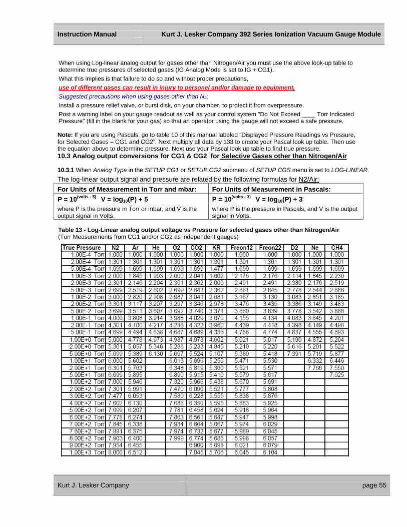
Instruction Manual Kurt J. Lesker Company 392 Series Ionization Vacuum Gauge Module
When using Log-linear analog output for gases other than Nitrogen/Air you must use the above look-up table to determine true pressures of selected gases (IG Analog Mode is set to IG + CG1). What this implies is that failure to do so and without proper precautions, use of different gases can result in injury to personel and/or damage to equipment. Suggested precautions when using gases other than N2: Install a pressure relief valve, or burst disk, on your chamber, to protect it from overpressure. Post a warning label on your gauge readout as well as your control system "Do Not Exceed ____ Torr Indicated Pressure" (fill in the blank for your gas) so that an operator using the gauge will not exceed a safe pressure. Note: If you are using Pascals, go to table 10 of this manual labeled “Displayed Pressure Readings vs Pressure, for Selected Gases – CG1 and CG2”. Next multiply all data by 133 to create your Pascal look up table. Then use the equation above to determine pressure. Next use your Pascal look up table to find true pressure. 10.3 Analog output conversions for CG1 & CG2 for Selective Gases other than Nitrogen/Air 10.3.1 When Analog Type in the SETUP CG1 or SETUP CG2 submenu of SETUP CGS menu is set to LOG-LINEAR. The log-linear output signal and pressure are related by the following formulas for N2/Air: For Units of Measurement in Torr and mbar: For Units of Measurement in Pascals: P = 10(volts - 5) V = log10(P) + 5 P = 10(volts - 3) V = log10(P) + 3 where P is the pressure in Torr or mbar, and V is the output signal in Volts.
where P is the pressure in Pascals, and V is the output signal in Volts.
Table 13 - Log-Linear analog output voltage vs Pressure for selected gases other than Nitrogen/Air (Torr Measurements from CG1 and/or CG2 as independent gauges)
Kurt J. Lesker Company page 55
Instruction Manual Kurt J. Lesker Company 392 Series Ionization Vacuum Gauge Module
When using Log-linear analog output for gases other than Nitrogen/Air you must use the above look-up table to determine true pressures of selected gases (CG1 and/or CG2 Analog Mode is set to Log-Linear). What this implies is that failure to do so and without proper precautions, use of different gases can result in injury to personnel and/or damage to equipment. Suggested precautions when using gases other than N2: Install a pressure relief valve, or burst disk, on your chamber, to protect it from overpressure. Post a warning label on your gauge readout as well as your control system "Do Not Exceed ____ Torr Indicated Pressure" (fill in the blank for your gas) so that an operator using the gauge will not exceed a safe pressure. Note: If you are using Pascals, go to table 10 of this manual labeled “Displayed Pressure Readings vs Pressure, for Selected Gases – CG1 and CG2”. Next multiply all data by 133 to create your Pascal look up table. Then use the equation above to determine pressure. Next use your Pascal look up table to find true pressure. 10.3.2 Non-Linear Analog Output conversions for Convection Gauges for selective Gases other than Nitrogen/Air When Analog Type in the SETUP CG1 or SETUP CG2 submenu of SETUP CGS menu is set to NON-LINEAR. Convection Gauge Analog output: Non-Linear S-Curve By design, these values are identical to the outputs from Brooks Automation/Granville-Phillips Convectron® gauges, Mini-Convectron® modules, and Controllers, so that equivalent units can be interchanged without affecting your process system or software. (See section 8.4 for more details).
Table 14 – Non-Linear analog output voltage vs Pressure for selected gases other than Nitrogen/Air (Torr Measurements from CG1 or CG2 as independent gauges)
Kurt J. Lesker Company page 56
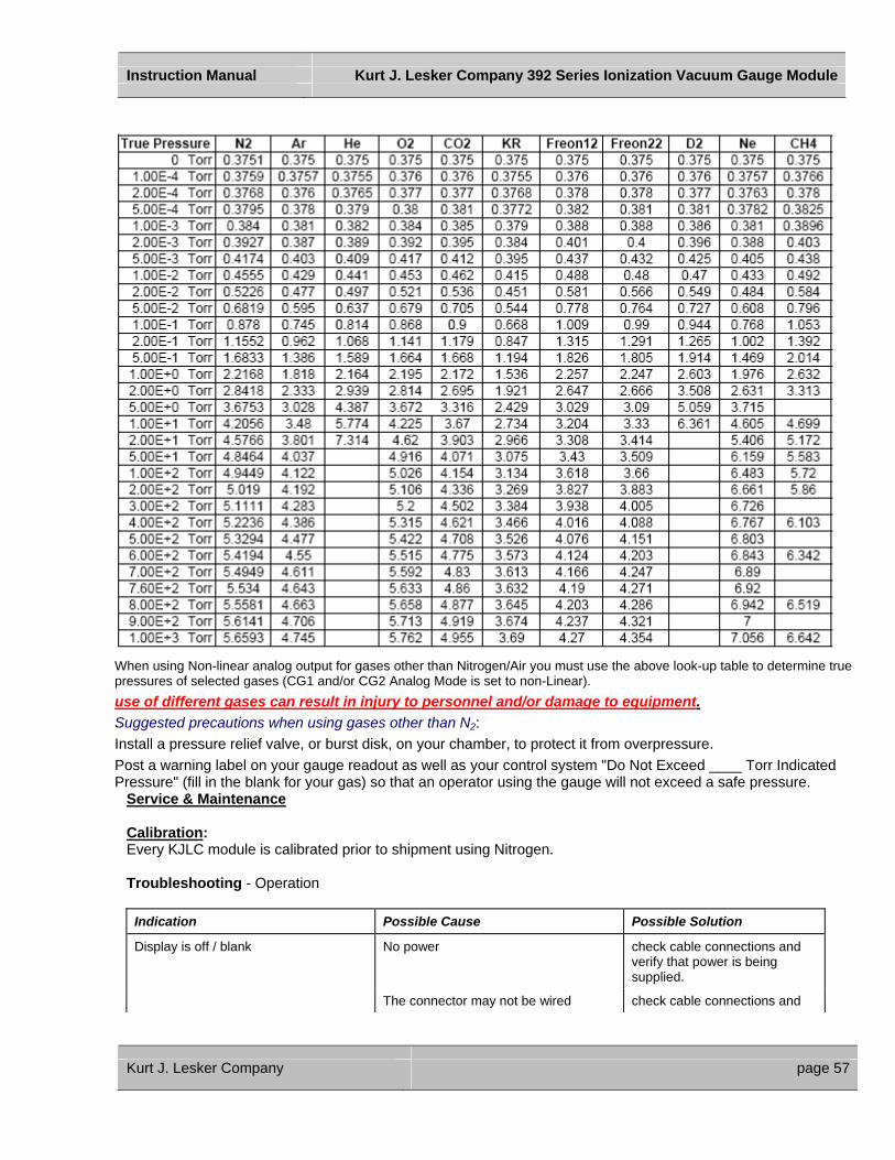
Instruction Manual Kurt J. Lesker Company 392 Series Ionization Vacuum Gauge Module
When using Non-linear analog output for gases other than Nitrogen/Air you must use the above look-up table to determine true pressures of selected gases (CG1 and/or CG2 Analog Mode is set to non-Linear). use of different gases can result in injury to personnel and/or damage to equipment. Suggested precautions when using gases other than N2: Install a pressure relief valve, or burst disk, on your chamber, to protect it from overpressure. Post a warning label on your gauge readout as well as your control system "Do Not Exceed ____ Torr Indicated Pressure" (fill in the blank for your gas) so that an operator using the gauge will not exceed a safe pressure.
Service & Maintenance Calibration: Every KJLC module is calibrated prior to shipment using Nitrogen. Troubleshooting - Operation
Indication Possible Cause Possible Solution
Display is off / blank No power check cable connections and verify that power is being supplied.
The connector may not be wired check cable connections and
Kurt J. Lesker Company page 57

Instruction Manual Kurt J. Lesker Company 392 Series Ionization Vacuum Gauge Module
correctly verify that power is being supplied.
Readings appear very different from expected pressure
Sensor not in the proper location to measure system pressure
The process gas is different from the gas (Nitrogen) used to calibrate the KJLC392.
ensure the sensor is located in appropriate location
apply gas sensitivity correction factor if applicable. See Table 3 or select the appropriate gas from the KJLC392 display menu
Sensor has been dropped causing mechanical damage
replace the Ion gauge sensor tube
The gauge sensor tube is contaminated degas the sensor or replace the sensor
Leak in the vacuum system
Re-check for leak in the system Re-check that all metal seals are used when operating below 1.0E-07 TORR
Ion gauge can not be turned on Pressure exceeds 1.00E-03 TORR at
4 ma emission
Pressure exceeds 5.0E-02 TORR at 0.10 ma (100uA) emission
Emission Control not functioning
decrease pressure below required value
decrease pressure below required value
switch to the other filament replace Ion gauge sensor tube due to possible filament failure or contamination
Research Screen shows filament Voltage is present but filament current stays at 0
Filament is open switch to the other filament or replace sensor
Research Screen shows filament voltage and filament current are present but gauge is shutting off
Filament is contaminated or burned out switch to the other filament or replace sensor
Unable to initiate Degas System pressure above 5.0 x10⁻⁵ decrease pressure below the required value
Voltage to filament too high Filament contaminated or near end of its life
switch to the other filament or replace sensor
Setpoint does not actuate Incorrect setup check setpoint setup Troubleshooting – Error Messages
Indication Possible Cause Possible Solution
OVERPRESSURE The calculated pressure is greater than maximum setting for emission current. System pressure too high.
Change to 100uA emission current which will operate at higher pressures or reduce pressure
ION CUR FAIL The Ion current (IC) is below the minimum parameter. Sensor contamination, possible coating on collector inhibiting ion collection
Determine source of contamination. Replace the Ion gauge sensor tube.
Kurt J. Lesker Company page 58
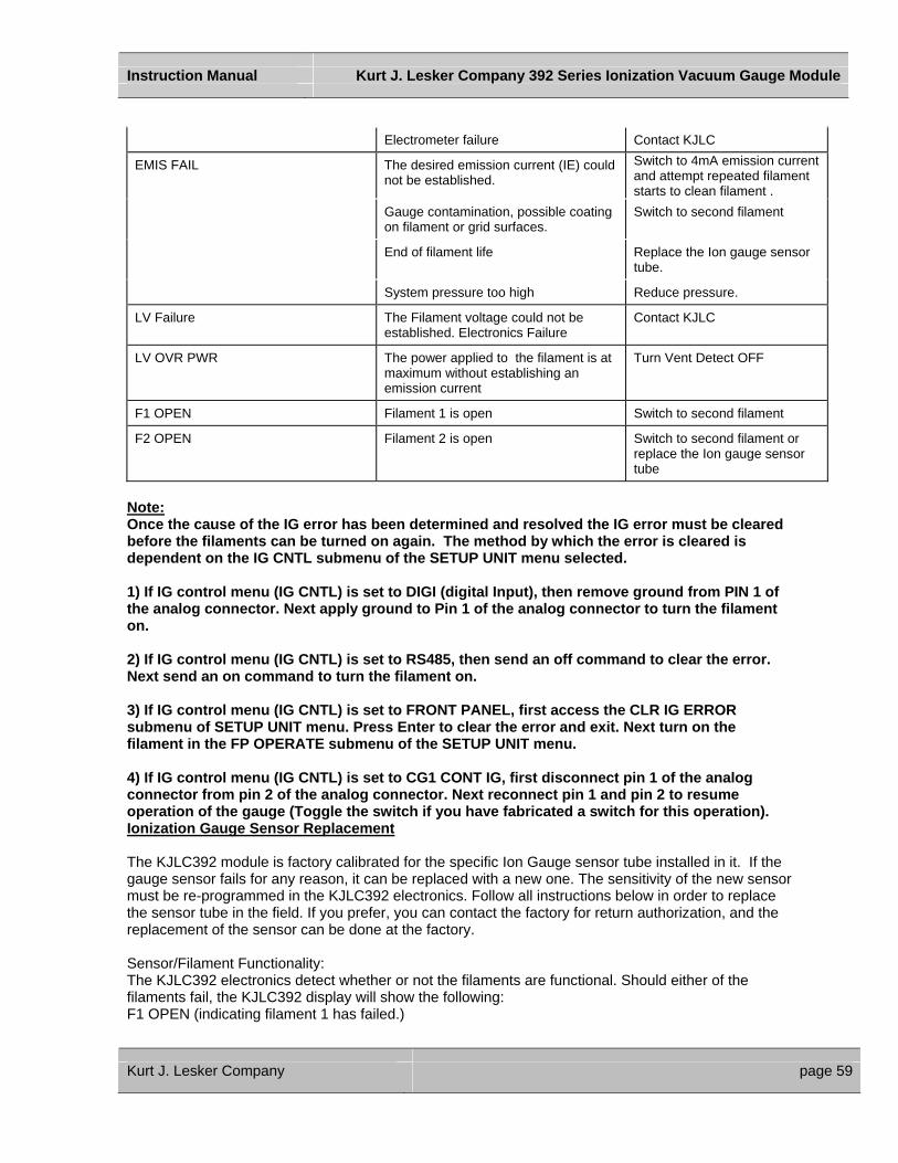
Instruction Manual Kurt J. Lesker Company 392 Series Ionization Vacuum Gauge Module
Electrometer failure Contact KJLC
EMIS FAIL The desired emission current (IE) could not be established.
Switch to 4mA emission current and attempt repeated filament starts to clean filament .
Gauge contamination, possible coating on filament or grid surfaces.
Switch to second filament
End of filament life Replace the Ion gauge sensor tube.
System pressure too high Reduce pressure.
LV Failure The Filament voltage could not be established. Electronics Failure
Contact KJLC
LV OVR PWR The power applied to the filament is at maximum without establishing an emission current
Turn Vent Detect OFF
F1 OPEN Filament 1 is open Switch to second filament
F2 OPEN Filament 2 is open Switch to second filament or replace the Ion gauge sensor tube
Note: Once the cause of the IG error has been determined and resolved the IG error must be cleared before the filaments can be turned on again. The method by which the error is cleared is dependent on the IG CNTL submenu of the SETUP UNIT menu selected. 1) If IG control menu (IG CNTL) is set to DIGI (digital Input), then remove ground from PIN 1 of the analog connector. Next apply ground to Pin 1 of the analog connector to turn the filament on. 2) If IG control menu (IG CNTL) is set to RS485, then send an off command to clear the error. Next send an on command to turn the filament on. 3) If IG control menu (IG CNTL) is set to FRONT PANEL, first access the CLR IG ERROR submenu of SETUP UNIT menu. Press Enter to clear the error and exit. Next turn on the filament in the FP OPERATE submenu of the SETUP UNIT menu. 4) If IG control menu (IG CNTL) is set to CG1 CONT IG, first disconnect pin 1 of the analog connector from pin 2 of the analog connector. Next reconnect pin 1 and pin 2 to resume operation of the gauge (Toggle the switch if you have fabricated a switch for this operation). Ionization Gauge Sensor Replacement The KJLC392 module is factory calibrated for the specific Ion Gauge sensor tube installed in it. If the gauge sensor fails for any reason, it can be replaced with a new one. The sensitivity of the new sensor must be re-programmed in the KJLC392 electronics. Follow all instructions below in order to replace the sensor tube in the field. If you prefer, you can contact the factory for return authorization, and the replacement of the sensor can be done at the factory. Sensor/Filament Functionality: The KJLC392 electronics detect whether or not the filaments are functional. Should either of the filaments fail, the KJLC392 display will show the following: F1 OPEN (indicating filament 1 has failed.)
Kurt J. Lesker Company page 59

Instruction Manual Kurt J. Lesker Company 392 Series Ionization Vacuum Gauge Module
F2 OPEN (indicating filament 2 has failed.) Sensor Replacement: To replace the sensor use the following procedure: 1. Turn off power to the unit. 2. Disconnect the cable from the unit. 3. Remove the KJLC392 from the vacuum system. 4. Use 3/32 size Allen Wrench to remove the #4-40 socket head cap screws as shown below. 5. Detach the metal enclosure and the electronics from the sensor. 6. Replace sensor. 7. Reprogram new sensor’s sensitivity.
Figure 14 – KJLC392 Sensor Replacement Warranty SELLER warrants that its products, are free of defects in workmanship and material and fit for the uses set forth in SELLER's catalog or product specifications, under the normal use and service for which they are intended. The entire warranty obligation of SELLER is for the repair or replacement, at SELLER's option, of products or parts (examination of which shall disclose to SELLER's satisfaction that it is defective) returned, to SELLER's plant, properly identified within eighteen (18) months (unless otherwise noted) after the date of shipment from KJLC Plant. BUYER must obtain the approval of SELLER and a return authorization number prior to shipment. Alteration or removal of serial numbers or other identification marks renders this warranty void. The warranty does not apply to products or components which have been abused, altered, operated
Kurt J. Lesker Company page 60
Instruction Manual Kurt J. Lesker Company 392 Series Ionization Vacuum Gauge Module
outside of the environmental specifications of the product, improperly handled or installed, or units which have not been operated in accordance with SELLER's instructions. Furthermore the warranty does not apply to products that have been contaminated, or when the product or part is damaged during the warranty period due to causes other than ordinary wear and tear to the product including, but not limited to, accidents, transportation, neglect, misuse, use of the product for any purpose other than that for which it was designed. THIS WARRANTY IS EXCLUSIVE AND IN LIEU OF ALL OTHER WARRANTIES, EXPRESS OR IMPLIED, INCLUDING ANY IMPLIED WARRANTY OF MERCHANTABILITY OR FITNESS FOR A PARTICULAR PURPOSE. THIS WARRANTY EXTENDS ONLY IN FAVOR OF THE ORIGINAL BUYER. THE BUYER'S SOLE REMEDY SHALL BE THE REPAIR OR REPLACEMENT, AS IS EXPRESSLY PROVIDED HEREIN, OF ANY WARRANTED DEFECTIVE PRODUCT OR PART, AND UNDER NO CIRCUMSTANCE SHALL SELLER BE LIABLE TO BUYER OR ANYONE ELSE FOR ANY CONSEQUENTIAL DAMAGES TO PERSONS OR PROPERTY, FOR INCIDENTAL DAMAGES OR LOSS OF TIME, FOR ANTICPATED OR LOST PROFITS, OR ANY OTHER LOSS INCURRED BY THE BUYER RELATED TO THE PRODUCT COVERED BY THIS WARRANTY. THIS EXCLUSIVE REMEDY SHALL NOT BE DEEMED TO HAVE FAILED OF ITS ESSENTIAL PURPOSE SO LONG AS SELLER IS WILLING AND ABLE TO REPAIR OR REPLACE DEFECTIVE PARTS IN THE PRESCRIBED MANNER. THIS LIMITED WARRANTY MAY NOT BE MODIFIED BY SELLER UNLESS SUCH MODIFICATION OR WAIVER IS IN WRITING, EXECUTED BY AN AUTHORIZED OFFICER OF SELLER. Trademarks & Acknowledgements These trademarks, used throughout this manual, are the property of the following companies: Micro-Ion®, Convectron® are registered trademarks of Brooks Automation/Helix Technology Corp/Granville Phillips. Conflat® and Mini-Conflat® are registered trademarks of Varian Vacuum Technology. Cajon® and VCR® are registered trademarks of the Swagelok Company. Teflon® is a registered trademark of DuPont.
Kurt J. Lesker Company page 61


