Ionization Detectors - Astronomypetra/phys6771/lecture14.pdfIonization Detectors Mostly Gaseous...
26
Ionization Detectors Mostly Gaseous Detectors
Transcript of Ionization Detectors - Astronomypetra/phys6771/lecture14.pdfIonization Detectors Mostly Gaseous...
Ionization Detectors
Mostly Gaseous Detectors
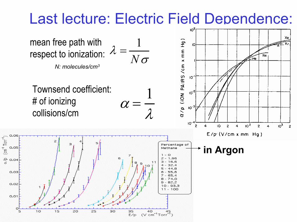
Last lecture: Electric Field Dependence:
λ =1Nσ
mean free path withrespect to ionization:
N: molecules/cm3
α =1λ
Townsend coefficient:# of ionizingcollisions/cm
in Argon
The Cylindrical Proportional Counter
• Basis of more sophisticated particle tracking detectors
• Simple proportional counter is generally used for detecting low energy x-rays on the order of a few keVand very low energy electrons from sources
• With a filling of gas of high neutron capture cross section (BF3, 3He), they can also be used for thermal or epithermal neutron detection
• In general, fill gases are at normal atmospheric pressure, but to increase density → efficiency, higher pressures may be used
The Cylindrical Proportional
Counter
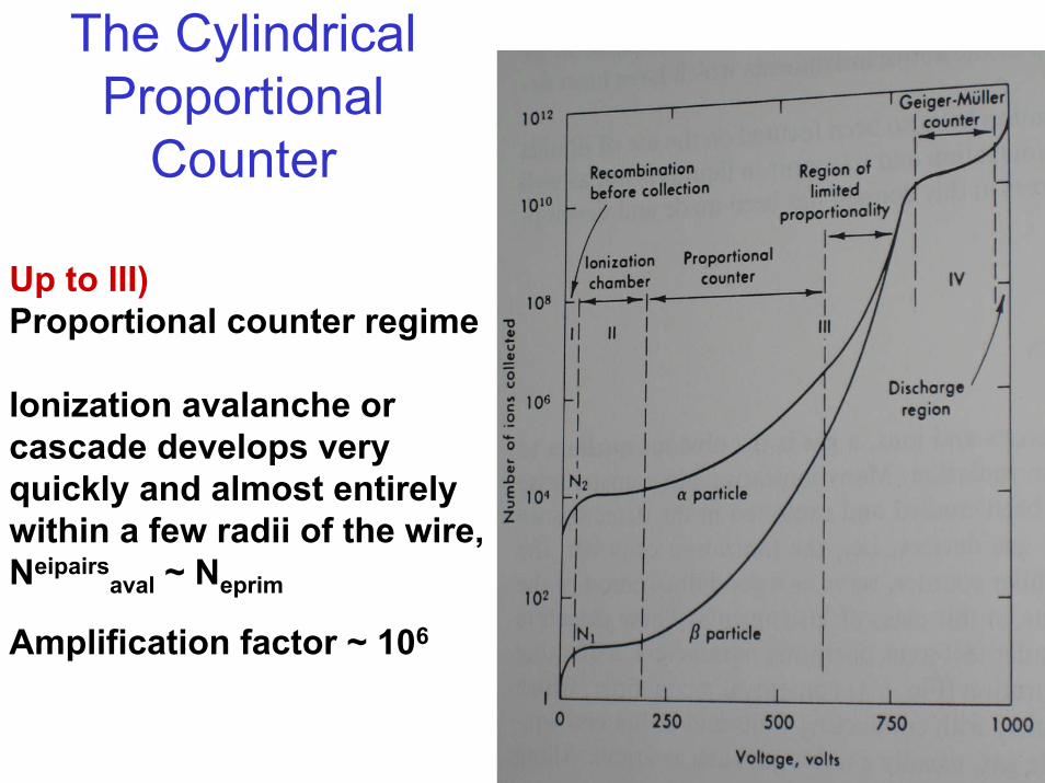
Up to III)Proportional counter regime
Ionization avalanche or cascade develops very quickly and almost entirely within a few radii of the wire, Neipairs
aval ~ Neprim
Amplification factor ~ 106
The Cylindrical Proportional Counter
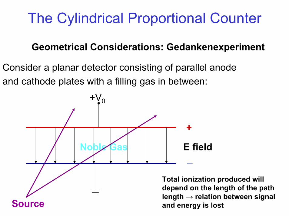
Geometrical Considerations: Gedankenexperiment
Consider a planar detector consisting of parallel anode and cathode plates with a filling gas in between:
Noble Gas
Source
+V0
+
_E field
Total ionization produced will depend on the length of the pathlength → relation between signal and energy is lost
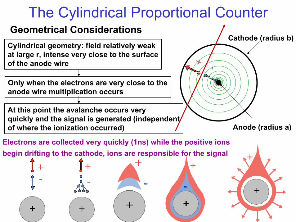
The Cylindrical Proportional CounterCathode (radius b)
Only when the electrons are very close to theanode wire multiplication occurs
At this point the avalanche occurs very quickly and the signal is generated (independentof where the ionization occurred)
Geometrical ConsiderationsCylindrical geometry: field relatively weakat large r, intense very close to the surfaceof the anode wire
Anode (radius a)
+
+-
+-
+
+
+
+
Electrons are collected very quickly (1ns) while the positive ionsbegin drifting to the cathode, ions are responsible for the signal
+
+
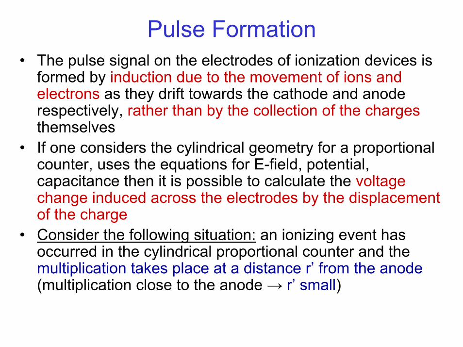
Pulse Formation• The pulse signal on the electrodes of ionization devices is
formed by induction due to the movement of ions and electrons as they drift towards the cathode and anode respectively, rather than by the collection of the chargesthemselves
• If one considers the cylindrical geometry for a proportional counter, uses the equations for E-field, potential, capacitance then it is possible to calculate the voltage change induced across the electrodes by the displacement of the charge
• Consider the following situation: an ionizing event has occurred in the cylindrical proportional counter and the multiplication takes place at a distance r’ from the anode(multiplication close to the anode → r’ small)
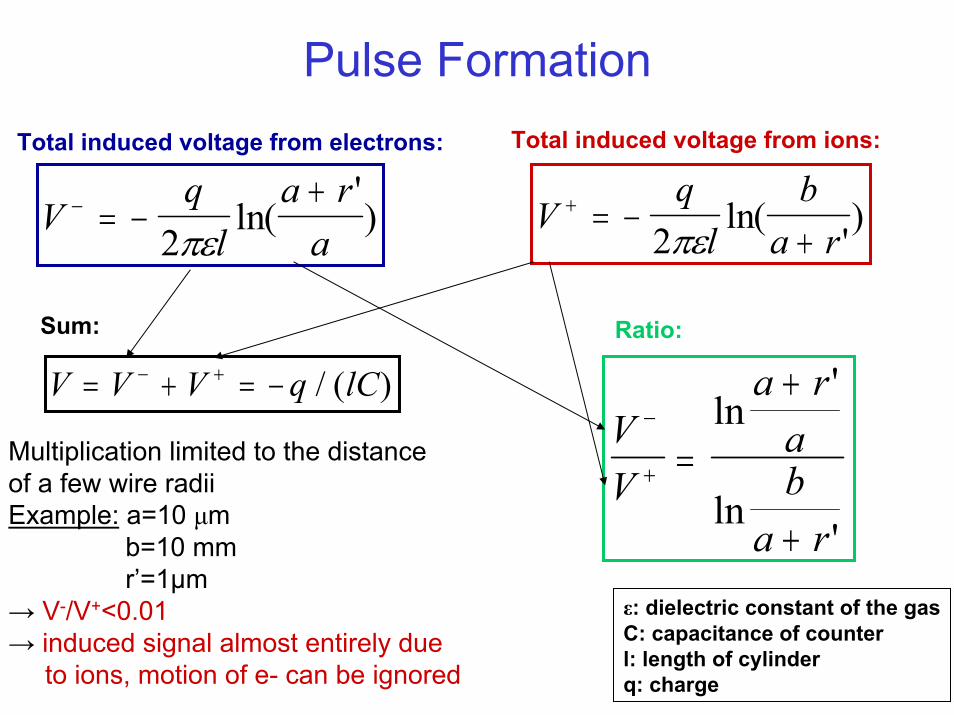
Pulse FormationTotal induced voltage from ions:Total induced voltage from electrons:
Vql
a ra
− = −+
2πεln(
') V
ql
ba r
+ = −+2πε
ln(')
V V V q lC= + = −− + / ( )VV
a raba r
−
+ =
+
+
ln'
ln'
Sum: Ratio:
Multiplication limited to the distanceof a few wire radiiExample: a=10 µm
b=10 mmr’=1µm
→ V-/V+<0.01→ induced signal almost entirely due
to ions, motion of e- can be ignored
ε: dielectric constant of the gasC: capacitance of counterl: length of cylinderq: charge
Choice of Fill Gas• Choice is governed by several factors:
– Low working voltage– High gain– Good proportionality– High rate capability
• Usually these conditions are met by gas mixtures rather than pure gases
• For minimum working voltage: noble gases since they require the lowest E-field intensities for avalanche formation
• preferred usually: Argon → high specific ionization and low cost
• Pure Argon cannot be operated at gains of more then 103-104 (above that continuous discharge will occur, photons will be emitted by the excited Argon atoms in the avalanche with high enough energy to ionize the cathode → further avalnches)
Choice of Fill Gas
• Remedy of discharge: addition of polyatomic gas like Methane, Alcohol, CO2, or BF3→ called quenchers which absorb the emitted photons and then dissipate their energy through dissociation or elastic collisions
• Conventional proportional counters filled with P10 gas (90% Argon + 10% Methane) have gains of 106
• Other often used quench gas: isobutane• Gain can be further increased to 107 by adding
electronegative gas such as freon (CF3Br), these gases do not only absorb photons but can also trap electrons extracted from the cathode (because of the high electric field) before they reach the anode and cause avalanches
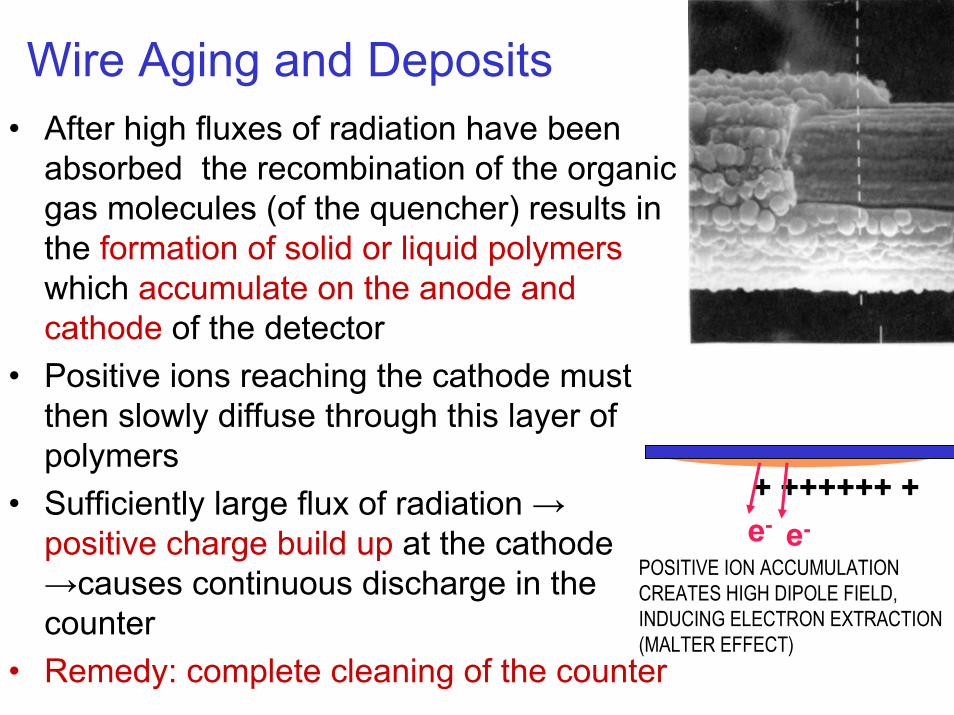
Wire Aging and Deposits• After high fluxes of radiation have been
absorbed the recombination of the organic gas molecules (of the quencher) results in the formation of solid or liquid polymerswhich accumulate on the anode and cathode of the detector
• Positive ions reaching the cathode must then slowly diffuse through this layer of polymers
• Sufficiently large flux of radiation →positive charge build up at the cathode →causes continuous discharge in the counter
• Remedy: complete cleaning of the counter
+ ++++++ +e- e-
POSITIVE ION ACCUMULATION CREATES HIGH DIPOLE FIELD,INDUCING ELECTRON EXTRACTION(MALTER EFFECT)
Wire Aging and Deposits• Possible solution: use of inorganic quenchers• However these are less efficient• Remedy instead: add small quantities of non-
polymerizing agents such as methylal or propylic alcohols
• These agents change the molecular ions at the cathode into a non-polymer species through an ion-exchange mechanism
Other problem with sealed counters:Large amounts of quenchers consumed (dissociated) in each detected event may change the operation characteristicsof the detector (can be avoided by continuous gas flow)
The Multiwire Proportional Counter• One of the basic requirements of experimental
particle physics is the determination of particle trajectories
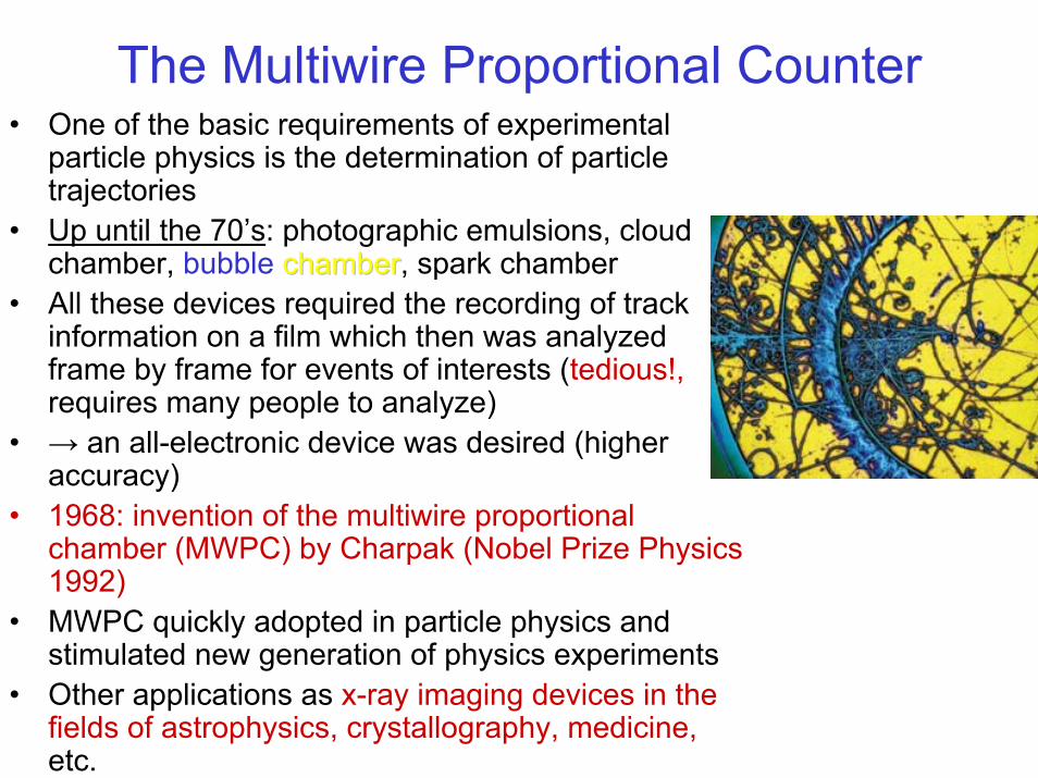
• Up until the 70’s: photographic emulsions, cloud chamber, bubble chamberchamber, spark chamber
• All these devices required the recording of track information on a film which then was analyzed frame by frame for events of interests (tedious!,requires many people to analyze)
• → an all-electronic device was desired (higher accuracy)
• 1968: invention of the multiwire proportional chamber (MWPC) by Charpak (Nobel Prize Physics 1992)
• MWPC quickly adopted in particle physics and stimulated new generation of physics experiments
• Other applications as x-ray imaging devices in the fields of astrophysics, crystallography, medicine,etc.
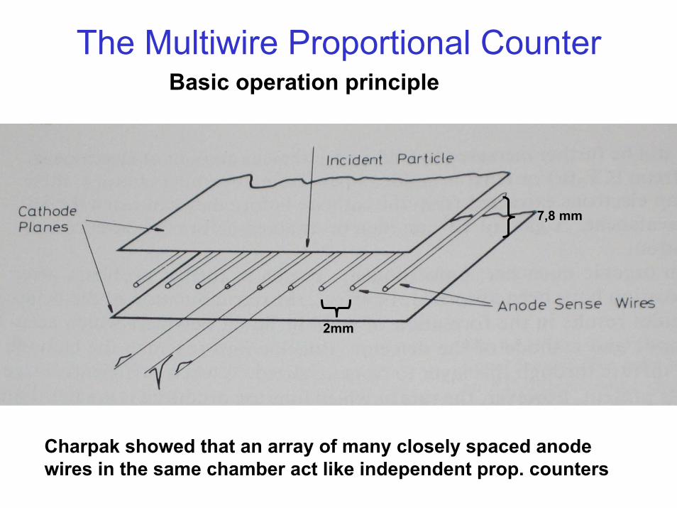
The Multiwire Proportional CounterBasic operation principle
2mm
7,8 mm
Charpak showed that an array of many closely spaced anode wires in the same chamber act like independent prop. counters
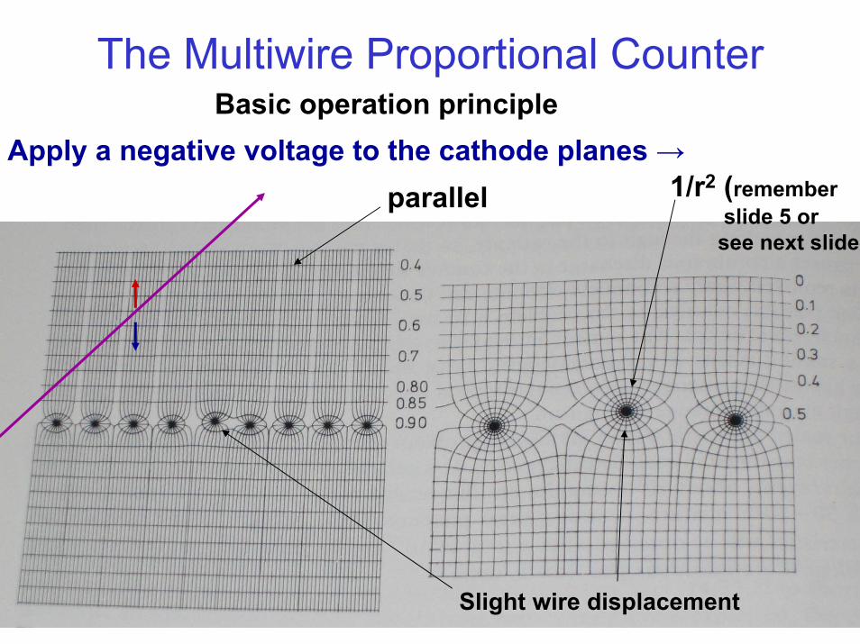
The Multiwire Proportional CounterBasic operation principle
Apply a negative voltage to the cathode planes →
Slight wire displacement
1/r2 (remember slide 5 orsee next slide)
parallel
The Multiwire Proportional CounterRemark: there is a postiveSignal induced on the neighboring wires, but ofsmall amplitude see plot onpage 13
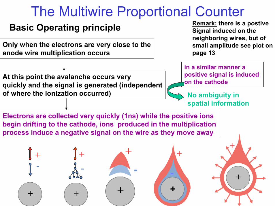
Basic Operating principle
Only when the electrons are very close to theanode wire multiplication occurs
in a similar manner a positive signal is induced on the cathode
No ambiguity inspatial information
At this point the avalanche occurs very quickly and the signal is generated (independentof where the ionization occurred)
+
+-
+-
+
+
+
+
+
+
Electrons are collected very quickly (1ns) while the positive ionsbegin drifting to the cathode, ions produced in the multiplication process induce a negative signal on the wire as they move away
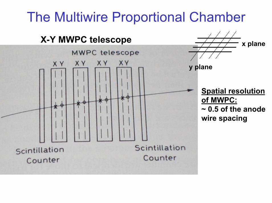
The Multiwire Proportional ChamberX-Y MWPC telescope
y plane
Spatial resolutionof MWPC: ~ 0.5 of the anodewire spacing
x plane
The Multiwire Proportional Chamber
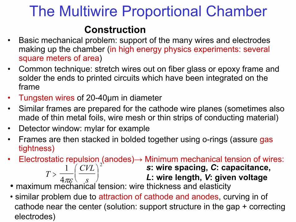
• Basic mechanical problem: support of the many wires and electrodes making up the chamber (in high energy physics experiments: several square meters of area)
• Common technique: stretch wires out on fiber glass or epoxy frame and solder the ends to printed circuits which have been integrated on the frame
• Tungsten wires of 20-40µm in diameter• Similar frames are prepared for the cathode wire planes (sometimes also
made of thin metal foils, wire mesh or thin strips of conducting material)• Detector window: mylar for example• Frames are then stacked in bolded together using o-rings (assure gas
tightness)• Electrostatic repulsion (anodes)→ Minimum mechanical tension of wires:
Construction
TCVLs
>
14
2
πεs: wire spacing, C: capacitance, L: wire length, V: given voltage
• maximum mechanical tension: wire thickness and elasticity• similar problem due to attraction of cathode and anodes, curving in of cathode near the center (solution: support structure in the gap + correctingelectrodes)
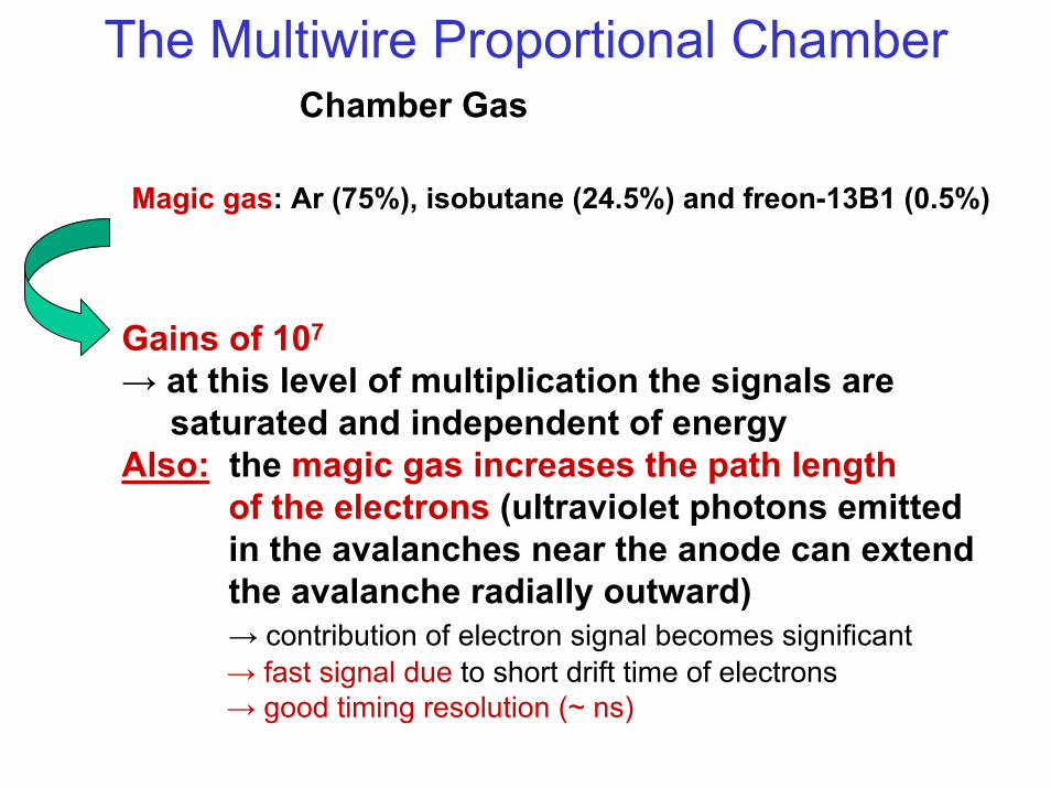
The Multiwire Proportional ChamberChamber Gas
Magic gas: Ar (75%), isobutane (24.5%) and freon-13B1 (0.5%)
Gains of 107
→ at this level of multiplication the signals are saturated and independent of energy
Also: the magic gas increases the path length of the electrons (ultraviolet photons emittedin the avalanches near the anode can extendthe avalanche radially outward)→ contribution of electron signal becomes significant→ fast signal due to short drift time of electrons→ good timing resolution (~ ns)
The Multiwire Proportional Chamber
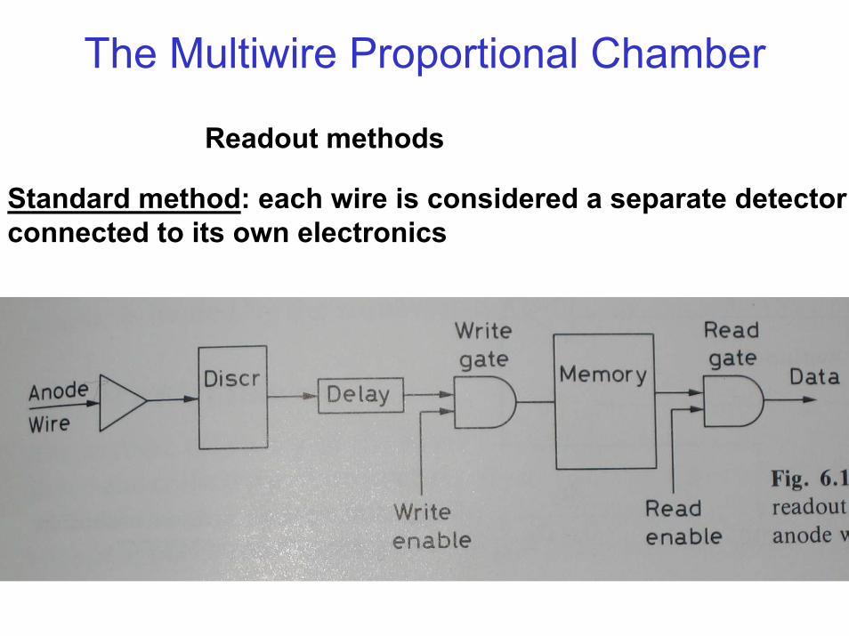
Readout methods
Standard method: each wire is considered a separate detectorconnected to its own electronics
The Multiwire Proportional Chamber
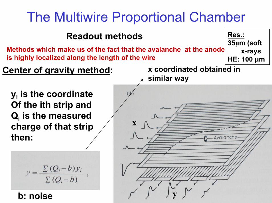
yi is the coordinateOf the ith strip andQi is the measured charge of that stripthen:
b: noise
x
y
Readout methods
Center of gravity method:
Methods which make us of the fact that the avalanche at the anodeis highly localized along the length of the wire
x coordinated obtained in similar way
Res.:35µm (soft
x-raysHE: 100 µm
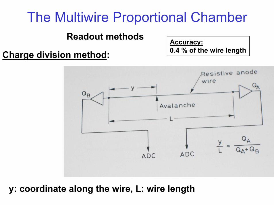
The Multiwire Proportional ChamberReadout methods
Accuracy:0.4 % of the wire lengthCharge division method:
y: coordinate along the wire, L: wire length
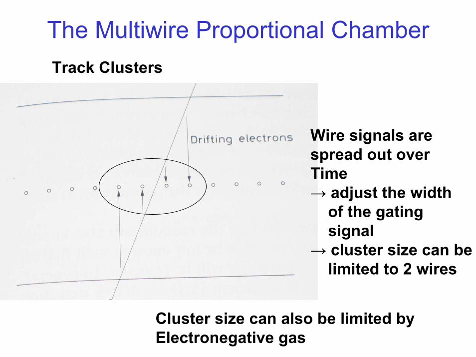
The Multiwire Proportional ChamberTrack Clusters
Wire signals arespread out overTime→ adjust the width
of the gatingsignal
→ cluster size can belimited to 2 wires
Cluster size can also be limited by Electronegative gas
The Multiwire Proportional Counter
• Intrinsic efficiency depends on the no. of electron-ion pairs produced and collected in the chamber – dE/dx of the fill gas, – the width of the gap, – the pressure of the gas, – the amount of electronegative gas, – the high voltage applied– The electronics,– etc.
• If gas is chosen properly, efficiency depends on electronics and high voltage (plot on page 148 in Leo)
• Efficiencies of 98-99% or more can be reached for charged particles• Measurement: placing a chamber in the beam of charged particles (for
example protons) together with two beam defining scintillation counters sandwiching the chamber
• Efficiency may be lowered by high count rate (charge build up)
Efficiency
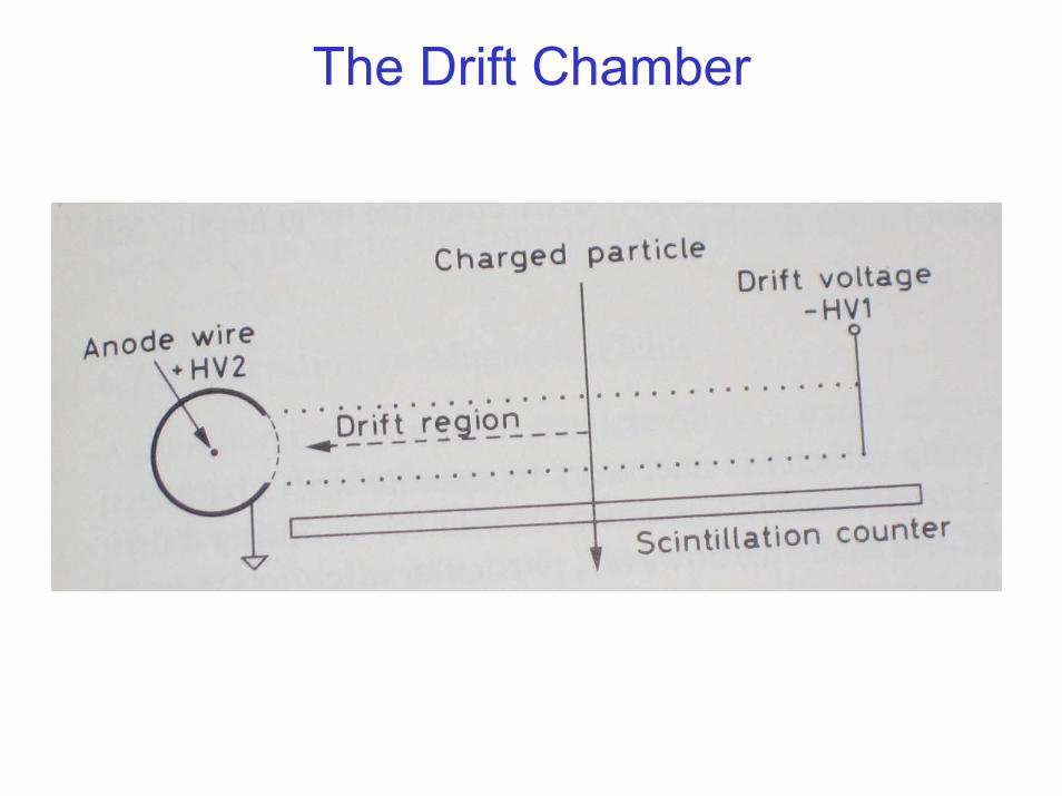
The Drift Chamber

Important dates
• Homework 5 due: Wednesday 7th
• Lab reports (except of the last lab): Wednesday 14th
• Last lab report due: Monday, 19th