Ion OneTouch 2 System - Thermo Fisher Scientific Research Use Only. Not for use in diagnostic...
71
For Research Use Only. Not for use in diagnostic procedures. Ion OneTouch ™ 2 System USER GUIDE For installation, setup, and maintenance of the Ion OneTouch ™ 2 Instrument and Ion OneTouch ™ ES Instrument Catalog Number 4474779 Publication Number MAN0014388 Revision A.0
Transcript of Ion OneTouch 2 System - Thermo Fisher Scientific Research Use Only. Not for use in diagnostic...

For Research Use Only. Not for use in diagnostic procedures.
Ion OneTouch™ 2 SystemUSER GUIDE
For installation, setup, and maintenance of the Ion OneTouch™ 2Instrument and Ion OneTouch™ ES Instrument
Catalog Number 4474779Publication Number MAN0014388
Revision A.0
The information in this guide is subject to change without notice.
DISCLAIMER
TO THE EXTENT ALLOWED BY LAW, LIFE TECHNOLOGIES AND/OR ITS AFFILIATE(S) WILL NOT BE LIABLE FOR SPECIAL, INCIDENTAL, INDIRECT,PUNITIVE, MULTIPLE, OR CONSEQUENTIAL DAMAGES IN CONNECTION WITH OR ARISING FROM THIS DOCUMENT, INCLUDING YOUR USE OF IT.
Important Licensing Information
These products may be covered by one or more Limited Use Label Licenses. By use of these products, you accept the terms and conditions of allapplicable Limited Use Label Licenses.
Corporate entity
Life Technologies | Carlsbad, CA 92008 USA | Toll Free in USA 1.800.955.6288
Trademarks
All trademarks are the property of Thermo Fisher Scientific and its subsidiaries unless otherwise specified. Kimwipes is a trademark of Kimberly-Clark Corporation. Eppendorf and Eppendorf LoBind are trademarks of Eppendorf AG. Luer-Lok is a trademark of Becton, Dickinson and Company.Parafilm is trademark of Bemis Company, Inc. Xiameter is a trademark of Dow Corning Corporation. Macintosh and Mac OS are trademarks of Apple,Inc. Microsoft, Windows, and Excel are trademarks of Microsoft Corporation.
©2015 Thermo Fisher Scientific Inc. All rights reserved.

Contents
About this guide . . . . . . . . . . . . . . . . . . . . . . . . . . . . . . . . . . . . . . . . . . . . . . . . . . . . . . . . . . . . 6
Revision history . . . . . . . . . . . . . . . . . . . . . . . . . . . . . . . . . . . . . . . . . . . . . . . . . . . . . . . . . . . . . . . . . 6
Purpose of the guide . . . . . . . . . . . . . . . . . . . . . . . . . . . . . . . . . . . . . . . . . . . . . . . . . . . . . . . . . . . . 6
■ CHAPTER 1 Product information . . . . . . . . . . . . . . . . . . . . . . . . . . . . . . . . . . . . . . . 7
Instrument system and components . . . . . . . . . . . . . . . . . . . . . . . . . . . . . . . . . . . . . . . . . . . . . . . 7
Required materials and equipment (not provided) . . . . . . . . . . . . . . . . . . . . . . . . . . . . . . . . . . . 8
■ CHAPTER 2 Ion OneTouch™ 2 Instrument installation, setup,and maintenance . . . . . . . . . . . . . . . . . . . . . . . . . . . . . . . . . . . . . . . . . . . . . . . . . . . . . . . . . 10
Instrument clearances . . . . . . . . . . . . . . . . . . . . . . . . . . . . . . . . . . . . . . . . . . . . . . . . . . . . . . . . . . 10
Unpack and install the Ion OneTouch™ 2 Instrument . . . . . . . . . . . . . . . . . . . . . . . . . . . . . . . . 10
Checking and updating the firmware on the Ion OneTouch™ 2 Instrument . . . . . . . . . . . . . . 11Check the firmware version . . . . . . . . . . . . . . . . . . . . . . . . . . . . . . . . . . . . . . . . . . . . . . . . . 11Install a firmware update with a USB flash drive . . . . . . . . . . . . . . . . . . . . . . . . . . . . . . . 11Alternative method: Install a firmware update using an ethernet connection . . . . . . 13
Ion OneTouch™ 2 Instrument touchscreen messages . . . . . . . . . . . . . . . . . . . . . . . . . . . . . . . . 14
Set up the Ion OneTouch™ 2 Instrument . . . . . . . . . . . . . . . . . . . . . . . . . . . . . . . . . . . . . . . . . . . 15Materials required for this procedure . . . . . . . . . . . . . . . . . . . . . . . . . . . . . . . . . . . . . . . . 16Install the Ion OneTouch™ Recovery Tubes and Ion OneTouch™ Recovery Router . . . . 16Install the Ion OneTouch™ 2 Amplification Plate . . . . . . . . . . . . . . . . . . . . . . . . . . . . . . . 17Install the disposable injector . . . . . . . . . . . . . . . . . . . . . . . . . . . . . . . . . . . . . . . . . . . . . . . 18Install the Ion OneTouch™ Oil . . . . . . . . . . . . . . . . . . . . . . . . . . . . . . . . . . . . . . . . . . . . . . . . 19Install the Ion OneTouch™ Recovery Solution . . . . . . . . . . . . . . . . . . . . . . . . . . . . . . . . . . 19Empty the Waste Container . . . . . . . . . . . . . . . . . . . . . . . . . . . . . . . . . . . . . . . . . . . . . . . . . 20Inspect the oil waste tray . . . . . . . . . . . . . . . . . . . . . . . . . . . . . . . . . . . . . . . . . . . . . . . . . . . 20Install the Ion OneTouch™ 2 Cleaning Adapter . . . . . . . . . . . . . . . . . . . . . . . . . . . . . . . . . 20
Initialize the instrument . . . . . . . . . . . . . . . . . . . . . . . . . . . . . . . . . . . . . . . . . . . . . . . . . . . . . . . . 21Complete the set up . . . . . . . . . . . . . . . . . . . . . . . . . . . . . . . . . . . . . . . . . . . . . . . . . . . . . . . . 22
Perform a verification run . . . . . . . . . . . . . . . . . . . . . . . . . . . . . . . . . . . . . . . . . . . . . . . . . . . . . . . 22
Ion OneTouch™ 2 Instrument maintenance . . . . . . . . . . . . . . . . . . . . . . . . . . . . . . . . . . . . . . . . . 23Clean the Ion OneTouch™ 2 Instrument . . . . . . . . . . . . . . . . . . . . . . . . . . . . . . . . . . . . . . . 23
Ion OneTouch™ 2 System User Guide 3

Ion OneTouch™ 2 Instrument decontamination . . . . . . . . . . . . . . . . . . . . . . . . . . . . . . . . . . . . . 26Materials and equipment required . . . . . . . . . . . . . . . . . . . . . . . . . . . . . . . . . . . . . . . . . . . 26Decontaminate the instrument . . . . . . . . . . . . . . . . . . . . . . . . . . . . . . . . . . . . . . . . . . . . . . 26
Download the log files from the Ion OneTouch™ 2 Instrument . . . . . . . . . . . . . . . . . . . . . . . . 26
■ CHAPTER 3 Ion OneTouch™ ES Instrument installation, setup,and maintenance . . . . . . . . . . . . . . . . . . . . . . . . . . . . . . . . . . . . . . . . . . . . . . . . . . . . . . . . . 28
Instrument clearances . . . . . . . . . . . . . . . . . . . . . . . . . . . . . . . . . . . . . . . . . . . . . . . . . . . . . . . . . . 28
Unpack and install the Ion OneTouch™ ES Instrument . . . . . . . . . . . . . . . . . . . . . . . . . . . . . . . 28Install the AC line voltage fuse module . . . . . . . . . . . . . . . . . . . . . . . . . . . . . . . . . . . . . . . 30
Set up the OneTouch™ ES Instrument . . . . . . . . . . . . . . . . . . . . . . . . . . . . . . . . . . . . . . . . . . . . . 32Materials required for this procedure . . . . . . . . . . . . . . . . . . . . . . . . . . . . . . . . . . . . . . . . 32Set up the instrument . . . . . . . . . . . . . . . . . . . . . . . . . . . . . . . . . . . . . . . . . . . . . . . . . . . . . . 32
Ion OneTouch™ ES Instrument calibration . . . . . . . . . . . . . . . . . . . . . . . . . . . . . . . . . . . . . . . . . 37Calibrate the vertical axis . . . . . . . . . . . . . . . . . . . . . . . . . . . . . . . . . . . . . . . . . . . . . . . . . . . 37Calibrate the horizontal axis . . . . . . . . . . . . . . . . . . . . . . . . . . . . . . . . . . . . . . . . . . . . . . . . 39
Perform a residual volume test . . . . . . . . . . . . . . . . . . . . . . . . . . . . . . . . . . . . . . . . . . . . . . . . . . 40
Ion OneTouch™ ES maintenance . . . . . . . . . . . . . . . . . . . . . . . . . . . . . . . . . . . . . . . . . . . . . . . . . . 43Materials and equipment required . . . . . . . . . . . . . . . . . . . . . . . . . . . . . . . . . . . . . . . . . . . 43Ion OneTouch™ ES back panel layout . . . . . . . . . . . . . . . . . . . . . . . . . . . . . . . . . . . . . . . . . 43Disassemble and lubricate the syringe . . . . . . . . . . . . . . . . . . . . . . . . . . . . . . . . . . . . . . . 44Reassemble the syringe . . . . . . . . . . . . . . . . . . . . . . . . . . . . . . . . . . . . . . . . . . . . . . . . . . . . 47
Ion OneTouch™ ES decontamination . . . . . . . . . . . . . . . . . . . . . . . . . . . . . . . . . . . . . . . . . . . . . . 48Materials and equipment required . . . . . . . . . . . . . . . . . . . . . . . . . . . . . . . . . . . . . . . . . . . 48Decontaminate the instrument . . . . . . . . . . . . . . . . . . . . . . . . . . . . . . . . . . . . . . . . . . . . . . 48
■ CHAPTER 4 Set up and test the Ion Chip™ Minifuge . . . . . . . . . . . . . . . . . 49
Install the Ion S5™ /Ion Proton™ Rotor and Buckets . . . . . . . . . . . . . . . . . . . . . . . . . . . . . . . . . 49
Test the minifuge . . . . . . . . . . . . . . . . . . . . . . . . . . . . . . . . . . . . . . . . . . . . . . . . . . . . . . . . . . . . . . 51
■ CHAPTER 5 Demonstrated protocol: Switching betweenolder and newer template preparation kits . . . . . . . . . . . . . . . . . . . . . . . . . . . . 53
When switching is required . . . . . . . . . . . . . . . . . . . . . . . . . . . . . . . . . . . . . . . . . . . . . . . . . . . . . . 53
Required materials and equipment . . . . . . . . . . . . . . . . . . . . . . . . . . . . . . . . . . . . . . . . . . . . . . . 53
Before you begin . . . . . . . . . . . . . . . . . . . . . . . . . . . . . . . . . . . . . . . . . . . . . . . . . . . . . . . . . . . . . . . 54
Clean the Ion OneTouch™ 2 Instrument after the last run . . . . . . . . . . . . . . . . . . . . . . . . . . . . 54
Initialize the Ion OneTouch™ 2 Instrument . . . . . . . . . . . . . . . . . . . . . . . . . . . . . . . . . . . . . . . . . 55
Set up the Ion OneTouch™ 2 Instrument with the appropriate kit . . . . . . . . . . . . . . . . . . . . . . 56
Contents
4 Ion OneTouch™ 2 System User Guide
■ APPENDIX A Troubleshooting . . . . . . . . . . . . . . . . . . . . . . . . . . . . . . . . . . . . . . . . . 58
Ion OneTouch™ 2 Instrument . . . . . . . . . . . . . . . . . . . . . . . . . . . . . . . . . . . . . . . . . . . . . . . . . . . . 58
Ion OneTouch™ ES . . . . . . . . . . . . . . . . . . . . . . . . . . . . . . . . . . . . . . . . . . . . . . . . . . . . . . . . . . . . . 60
■ APPENDIX B Safety . . . . . . . . . . . . . . . . . . . . . . . . . . . . . . . . . . . . . . . . . . . . . . . . . . . . . 64
Symbols on this instrument . . . . . . . . . . . . . . . . . . . . . . . . . . . . . . . . . . . . . . . . . . . . . . . . . . . . . 64Conformity symbols on this instrument . . . . . . . . . . . . . . . . . . . . . . . . . . . . . . . . . . . . . . . 65
Safety alerts on this instrument . . . . . . . . . . . . . . . . . . . . . . . . . . . . . . . . . . . . . . . . . . . . . . . . . . 66Location of safety labels on the instrument . . . . . . . . . . . . . . . . . . . . . . . . . . . . . . . . . . . 66
Safety information for instruments not manufactured by Thermo Fisher Scientific . . . . . 67
Instrument safety . . . . . . . . . . . . . . . . . . . . . . . . . . . . . . . . . . . . . . . . . . . . . . . . . . . . . . . . . . . . . . 67General . . . . . . . . . . . . . . . . . . . . . . . . . . . . . . . . . . . . . . . . . . . . . . . . . . . . . . . . . . . . . . . . . . 67Electrical . . . . . . . . . . . . . . . . . . . . . . . . . . . . . . . . . . . . . . . . . . . . . . . . . . . . . . . . . . . . . . . . . 67Cleaning and decontamination . . . . . . . . . . . . . . . . . . . . . . . . . . . . . . . . . . . . . . . . . . . . . . . 67
Safety and electromagnetic compatibility (EMC) standards . . . . . . . . . . . . . . . . . . . . . . . . . . 68Safety . . . . . . . . . . . . . . . . . . . . . . . . . . . . . . . . . . . . . . . . . . . . . . . . . . . . . . . . . . . . . . . . . . . . 68Environmental design . . . . . . . . . . . . . . . . . . . . . . . . . . . . . . . . . . . . . . . . . . . . . . . . . . . . . . 68EMC . . . . . . . . . . . . . . . . . . . . . . . . . . . . . . . . . . . . . . . . . . . . . . . . . . . . . . . . . . . . . . . . . . . . . . 69
Chemical safety . . . . . . . . . . . . . . . . . . . . . . . . . . . . . . . . . . . . . . . . . . . . . . . . . . . . . . . . . . . . . . . . 69
■ Documentation and support . . . . . . . . . . . . . . . . . . . . . . . . . . . . . . . . . . . . . . . . . . . . . 70
Customer and technical support . . . . . . . . . . . . . . . . . . . . . . . . . . . . . . . . . . . . . . . . . . . . . . . . . 70
Limited product warranty . . . . . . . . . . . . . . . . . . . . . . . . . . . . . . . . . . . . . . . . . . . . . . . . . . . . . . . 70
Contents
Ion OneTouch™ 2 System User Guide 5
About this guide
CAUTION! ABBREVIATED SAFETY ALERTS. Hazard symbols and hazardtypes specified in procedures may be abbreviated in this document. For thecomplete safety information, see the “Safety” appendix in this document.
IMPORTANT! Before using this product, read and understand the information in the“Safety” appendix in this document.
Revision history
Revision Date Description
A.0 December 2015 Instrument user guide that includes instructions forinstallation, setup, and maintenance.
Purpose of the guide
The Ion OneTouch™ 2 System User Guide (Pub. no. MAN0014388) provides referenceinformation for the installation, setup, and maintenance of the Ion OneTouch™ 2System (Cat. no. 4474779), which includes the Ion OneTouch™ 2 Instrument and theIon OneTouch™ ES Instrument. For information about how to run these instruments,see the template kit-specific user guides.
6 Ion OneTouch™ 2 System User Guide
Product information
Instrument system and components
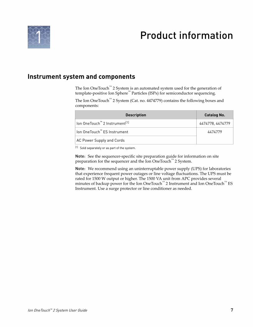
The Ion OneTouch™ 2 System is an automated system used for the generation oftemplate-positive Ion Sphere™ Particles (ISPs) for semiconductor sequencing.
The Ion OneTouch™ 2 System (Cat. no. 4474779) contains the following boxes andcomponents:
Description Catalog No.
Ion OneTouch™ 2 Instrument[1] 4474778, 4474779
Ion OneTouch™ ES Instrument 4474779
AC Power Supply and Cords
[1] Sold separately or as part of the system.
Note: See the sequencer-specific site preparation guide for information on sitepreparation for the sequencer and the Ion OneTouch™ 2 System.
Note: We recommend using an uninterruptable power supply (UPS) for laboratoriesthat experience frequent power outages or line voltage fluctuations. The UPS must berated for 1500 W output or higher. The 1500 VA unit from APC provides severalminutes of backup power for the Ion OneTouch™ 2 Instrument and Ion OneTouch™ ESInstrument. Use a surge protector or line conditioner as needed.
1
Ion OneTouch™ 2 System User Guide 7
Required materials and equipment (not provided)
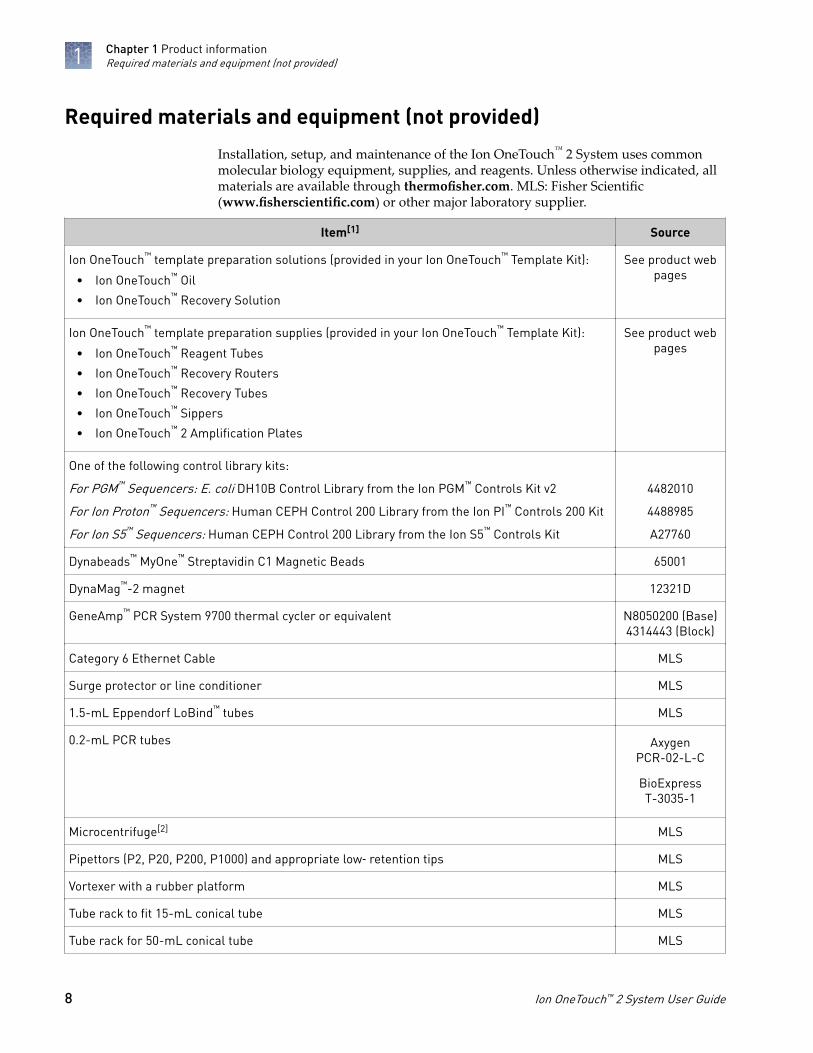
Installation, setup, and maintenance of the Ion OneTouch™ 2 System uses commonmolecular biology equipment, supplies, and reagents. Unless otherwise indicated, allmaterials are available through thermofisher.com. MLS: Fisher Scientific(www.fisherscientific.com) or other major laboratory supplier.
Item[1] Source
Ion OneTouch™ template preparation solutions (provided in your Ion OneTouch™ Template Kit):
• Ion OneTouch™ Oil
• Ion OneTouch™ Recovery Solution
See product webpages
Ion OneTouch™ template preparation supplies (provided in your Ion OneTouch™ Template Kit):
• Ion OneTouch™ Reagent Tubes
• Ion OneTouch™ Recovery Routers
• Ion OneTouch™ Recovery Tubes
• Ion OneTouch™ Sippers
• Ion OneTouch™ 2 Amplification Plates
See product webpages
One of the following control library kits:
For PGM™ Sequencers: E. coli DH10B Control Library from the Ion PGM™ Controls Kit v2
For Ion Proton™ Sequencers: Human CEPH Control 200 Library from the Ion PI™ Controls 200 Kit
For Ion S5™ Sequencers: Human CEPH Control 200 Library from the Ion S5™ Controls Kit
4482010
4488985
A27760
Dynabeads™ MyOne™ Streptavidin C1 Magnetic Beads 65001
DynaMag™-2 magnet 12321D
GeneAmp™ PCR System 9700 thermal cycler or equivalent N8050200 (Base)4314443 (Block)
Category 6 Ethernet Cable MLS
Surge protector or line conditioner MLS
1.5-mL Eppendorf LoBind™ tubes MLS
0.2-mL PCR tubes AxygenPCR-02-L-C
BioExpressT-3035-1
Microcentrifuge[2] MLS
Pipettors (P2, P20, P200, P1000) and appropriate low‑ retention tips MLS
Vortexer with a rubber platform MLS
Tube rack to fit 15-mL conical tube MLS
Tube rack for 50-mL conical tube MLS
Chapter 1 Product informationRequired materials and equipment (not provided)1
8 Ion OneTouch™ 2 System User Guide

Item[1] Source
1 M NaOH MLS
Bleach MLS
Xiameter™ PMX-200 Silicone Fluid[3] Neely IndustriesPMX200-12500PT
Benchtop absorbent paper or mat MLS
1/8-inch L-wrench (hex wrench) or equivalent tool MLS
[1] We have verified this protocol using these specific materials. Substitution may adversely affect system performance.[2] Must fit standard 1.5- and 0.2-mL microcentrifuge tubes; must generate 15,500 × g .[3] Material required for periodic maintenance of the Ion OneTouch™ ES.
Chapter 1 Product informationRequired materials and equipment (not provided) 1
Ion OneTouch™ 2 System User Guide 9

Ion OneTouch™ 2 Instrumentinstallation, setup, and maintenance
Instrument clearances
Position the instrument so that the front is a minimum of 12 in. (30.5 cm) from thefront of the laboratory bench. Place the instrument at least 40 in. (1 meter) away frommajor sources of electronic noise such as refrigerators or microwaves. For moreinformation, refer to the appropriate site preparation guide specific for yoursequencing system.
Unpack and install the Ion OneTouch™ 2 Instrument
For detailed instructions on site preparation and installation of the Ion OneTouch™ 2Instrument, refer to the site preparation and installation requirements in yoursequencing system site preparation guide.
1. Unpack and install the Ion OneTouch™ 2 Instrument in a location different fromthe location used to prepare the amplification solution. Remove the instrumentby laying the shipping box sideways on a table, then sliding out the instrument.
IMPORTANT! Do not lift the instrument by the metal handle used to access theIon OneTouch™ 2 Amplification Plate.
2. Ensure that the power switch is turned Off, then plug the power cord into theinstrument.
3. Plug the other end of the power cord into an electrical outlet of the appropriatevoltage.
IMPORTANT! The Ion OneTouch™ 2 Instrument draws 6 amps of current. Do notexceed the circuit breaker limit for current. If necessary, plug multipleinstruments into different circuits.
4. Turn the power switch On. Initial start-up takes ~3 minutes. You may hearsounds from the instrument. This is normal.
IMPORTANT! Leave the Ion OneTouch™ 2 Instrument On indefinitely. If theinstrument is turned off, critical log files are lost. If you need to turn off theinstrument or if a run fails, download the log files (see “Download the log filesfrom the Ion OneTouch™ 2 Instrument“ on page 26).
2
10 Ion OneTouch™ 2 System User Guide

Checking and updating the firmware on the Ion OneTouch™ 2Instrument
Firmware updates to the software controlling the Ion OneTouch™ 2 Instrument areperiodically released. To update the firmware to the appropriate version, use either aUSB flash drive or an ethernet connection, as described in the next sections.
IMPORTANT! Ensure that the latest firmware is installed on the Ion OneTouch™ 2Instrument. However, if you are using the Ion PGM™ Template OT2 200 Kit togetherwith the Ion PGM™ Hi-Q™ Sequencing Kit, do not upgrade to Torrent Suite™ Softwarev5.0 or later until you no longer require the mixed workflow. The OT2 program scriptenabling the mixed workflow is discontinued in v5.0. We recommend using the IonPGM™ Hi-Q™ OT2 Kit (Cat. no. A27739) together with the Ion PGM™ Hi-Q™
Sequencing Kit.
In the instrument touch screen, touch Options, then touch Info.
Firmware updates can only be installed by Administrator-level users on the TorrentServer connected to your Ion OneTouch™ 2 Instrument.
1. Ensure that the USB flash drive is FAT32-formatted. If your USB is not FAT32formatted, follow the instructions below to reformat it.
Note: Reformatting will erase on the data on the USB.
Operatingsystem Procedure…
Mac OS™1. Insert the USB flash drive into a USB port, then double-click the
Macintosh HDD icon.
2. Navigate to the Applications folder, then click: Utilities4DiskUtility.
3. Double-click the Disk Utility application.
4. Select the drive (the USB flash drive) to format, then clickErase.
5. From the volume format, select MS-DOS (FAT), then enter aname for the USB flash drive.
6. Click Erase, then confirm the FAT32 formatting.
Windows™1. Insert the USB flash drive into a USB port, then double-click My
Computer.
2. Right-click the USB flash drive icon, then select Format.
3. Select FAT32 from the drop‐down menu, click Start, thenconfirm the FAT32 formatting.
2. Log in to the Torrent Browser with an Administrator account user name andpassword.
Check thefirmware version
Install a firmwareupdate with a USBflash drive
Chapter 2 Ion OneTouch™ 2 Instrument installation, setup, and mainte-nance
Checking and updating the firmware on the Ion OneTouch™ 2 Instrument
2
Ion OneTouch™ 2 System User Guide 11
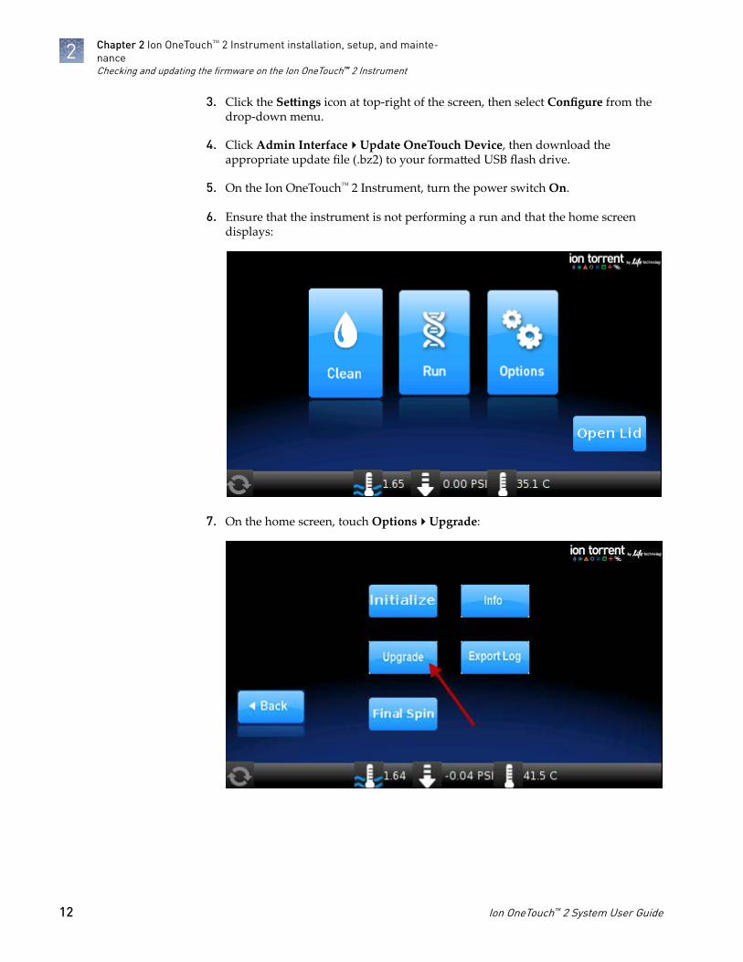
3. Click the Settings icon at top-right of the screen, then select Configure from thedrop-down menu.
4. Click Admin Interface4Update OneTouch Device, then download theappropriate update file (.bz2) to your formatted USB flash drive.
5. On the Ion OneTouch™ 2 Instrument, turn the power switch On.
6. Ensure that the instrument is not performing a run and that the home screendisplays:
7. On the home screen, touch Options4Upgrade:
Chapter 2 Ion OneTouch™ 2 Instrument installation, setup, and mainte-nanceChecking and updating the firmware on the Ion OneTouch™ 2 Instrument
2
12 Ion OneTouch™ 2 System User Guide

8. Insert the USB flash drive into the USB port, located on the back of theIon OneTouch™ 2 Instrument:
1
2
3
4
1 Ethernet connection2 USB port3 Power switch (on/off)4 Power socket
9. On the Upgrade screen, touch Yes.
10. Wait 10 seconds for the screen to display the software status update:• If the status update displays, proceed to step 11.• If the Options screen displays, then there are no firmware updates.
11. Touch Options4Info to ensure that the new version of the firmware update isinstalled.
12. Turn the power switch Off, wait several seconds, then remove the USB flashdrive.
13. Turn the power switch On.
Note: Use a shielded Category 6 ethernet cable to connect to the Ion OneTouch™ 2Instrument.
1. Turn the power switch Off.
2. Connect the Ion OneTouch™ 2 Instrument to the Torrent Server via a Category 6ethernet cable.
3. Turn the power switch On. Initial start-up takes ~3 minutes.
Note: You may hear sounds from the instrument. This is normal.
4. Log in to the Torrent Browser with an Administrator account user name andpassword.
5. Click the Settings icon at top-right of the screen, then select Configure from thedrop-down menu.
Alternativemethod: Install afirmware updateusing an ethernetconnection
Chapter 2 Ion OneTouch™ 2 Instrument installation, setup, and mainte-nance
Checking and updating the firmware on the Ion OneTouch™ 2 Instrument
2
Ion OneTouch™ 2 System User Guide 13

6. Click Admin Interface4Update OneTouch Device4Update then wait for theupdate to complete and the instrument to reset.
Note: A progress bar appears on the instrument during the update.
7. Touch Options on the Ion OneTouch™ 2 Instrument home page to ensure that thenew version of the firmware update is installed.
Ion OneTouch™ 2 Instrument touchscreen messages
If the on-screen message is... Then the instrument is...
Priming and Filling RecoverySolution
Priming the filter and filling the collection tubes withIon OneTouch™ Recovery Solution.
Sample Injection Injecting sample and starting emulsification.
Amplification Amplifying the sample by PCR.
Filling Recovery Solution Completely filling the Ion OneTouch™ Recovery Tubeswith Ion OneTouch™ Recovery Solution.
ISP Collection Breaking the emulsion and collecting the Ion Sphere™
Particles (ISPs).
Wash Cycles Washing the instrument and draining the washes.
Final Spin Performing final centrifugation to pellet the ISPs in theIon OneTouch™ Recovery Tubes.
Chapter 2 Ion OneTouch™ 2 Instrument installation, setup, and mainte-nanceIon OneTouch™ 2 Instrument touchscreen messages
2
14 Ion OneTouch™ 2 System User Guide

Set up the Ion OneTouch™ 2 Instrument
Before operating the Ion OneTouch™ 2 Instrument for the first time, you must performthe one-time initialization on the instrument. Initialization primes the pumps andtubing lines for reliable operation. Perform initialization at any time before the firstrun.
1
2
3
10
9
8
764 5
Ion OneTouch™ 2 Instrument layout1 Ion OneTouch™ Reaction Filter2 Clamp handle to access the Amplification
Plate in the heat block3 Waste Container4 Ion OneTouch™ Oil 5 Ion OneTouch™ Recovery Solution
6 Pinch valve to hold disposable tubing7 Oil waste tray8 Centrifuge to spin the Recovery Tubes and
Recovery Router9 Ion OneTouch™ DL Injector Hub
10 Instrument display
Chapter 2 Ion OneTouch™ 2 Instrument installation, setup, and mainte-nance
Set up the Ion OneTouch™ 2 Instrument
2
Ion OneTouch™ 2 System User Guide 15
Provided in your template preparation supplies kit:
• 2 Ion OneTouch™ Reagent Tubes
• Ion OneTouch™ Recovery Router
• 2 Ion OneTouch™ Recovery Tubes
• Ion OneTouch™ 2 Amplification Plate
• 2 Ion OneTouch™ Sipper Tubes
Provided in your template preparation solutions kit:
• Ion OneTouch™ Oil
• Ion OneTouch™ Recovery Solution
Note: This protocol has been verified using only the materials specified. Substitutionmay adversely affect performance and safety.
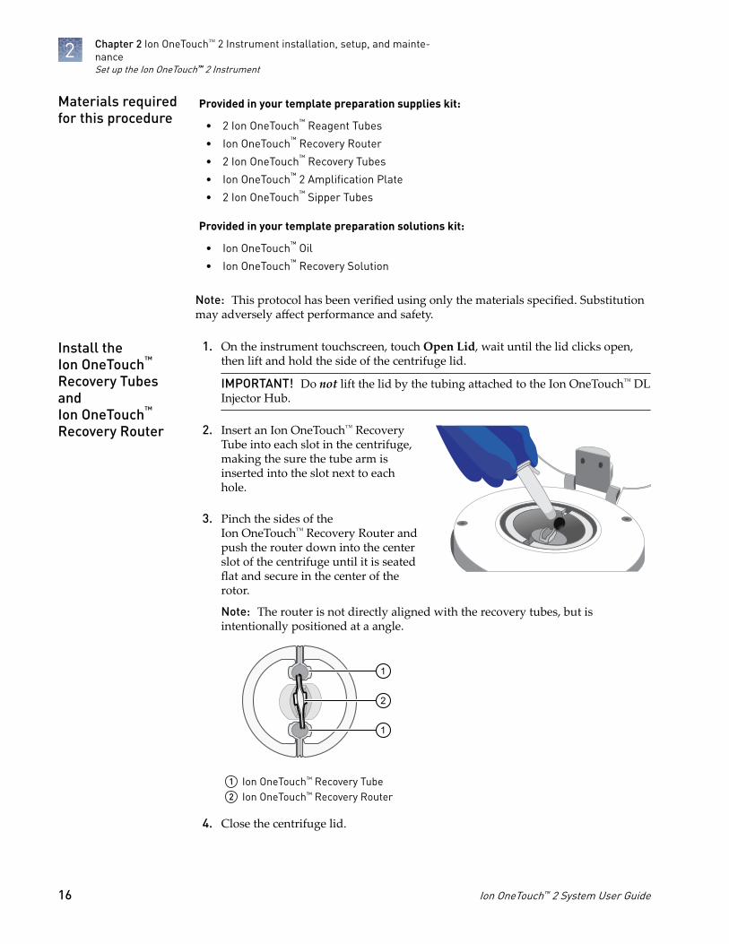
1. On the instrument touchscreen, touch Open Lid, wait until the lid clicks open,then lift and hold the side of the centrifuge lid.
IMPORTANT! Do not lift the lid by the tubing attached to the Ion OneTouch™ DLInjector Hub.
2. Insert an Ion OneTouch™ RecoveryTube into each slot in the centrifuge,making the sure the tube arm isinserted into the slot next to eachhole.
3. Pinch the sides of theIon OneTouch™ Recovery Router andpush the router down into the centerslot of the centrifuge until it is seatedflat and secure in the center of therotor.
Note: The router is not directly aligned with the recovery tubes, but isintentionally positioned at a angle.
2
1
1
1 Ion OneTouch™ Recovery Tube2 Ion OneTouch™ Recovery Router
4. Close the centrifuge lid.
Materials requiredfor this procedure
Install theIon OneTouch™
Recovery TubesandIon OneTouch™
Recovery Router
Chapter 2 Ion OneTouch™ 2 Instrument installation, setup, and mainte-nanceSet up the Ion OneTouch™ 2 Instrument
2
16 Ion OneTouch™ 2 System User Guide

1. If there is a used Ion OneTouch™ Cleaning Adapter on the instrument, removeand appropriately discard it.
Note: The Cleaning Adapter may be filled with Ion OneTouch™ Oil.
2. Push the handle back to open the heat block.
CAUTION! Hot Surface. Use care when working around this area to avoidbeing burned by hot components.
WARNING! Safety Hazard. Do not use the instrument with flammable orexplosive materials. Use only the materials specified for use with theinstrument to ensure safety.
3. Insert the Amplification Plate:a. Inspect the Ion OneTouch™ 2 Amplification Plate to ensure the plate port is
straight and perpendicular to the plate.
IMPORTANT! The disposable tubing and disposable injector are attached tothe Amplification Plate. Do not disconnect tubing from the top plate port. Ifyou have questions about the plate, contact Technical Support.
b. Hold the disposable injector, connected to the disposable tubing, in onehand and the Amplification Plate in the other hand.
CAUTION! PHYSICAL INJURY HAZARD. The pointed end of thedisposable injector can puncture your skin. Keep your hand awayfrom the point of the disposable injector.
c. Insert the Amplification Plate into the open instrument heat block, beingcareful to align the plate port with the left outlet hole on theIon OneTouch™ 2 Instrument:
4. Pull the handle forward to secure the amplification plate. The disposable tubingshould be under the handle.
Install theIon OneTouch™ 2AmplificationPlate
Chapter 2 Ion OneTouch™ 2 Instrument installation, setup, and mainte-nance
Set up the Ion OneTouch™ 2 Instrument
2
Ion OneTouch™ 2 System User Guide 17

5. Thread the disposable tubingthrough the Ion OneTouch™ DLTubing Catch, as shown below. Makesure that the tubing is not twisted.
6. Align the disposable tubing with theslot that runs along the bottom of the pinch valve. Gently pull the tubing up intothe slot until it is secured in the notch, as shown below.
7. Adjust the disposable line so that it is straight, but not too taut. Allow enoughline to install the disposable injector.
Note: The long metal shaft of the disposable injector may be slightly bent, which isnormal. If you have questions about the disposable injector, contact TechnicalSupport.
1. Ensure that the needle of the injector is screwed tightly onto the rubber tubing.Hold the centrifuge lid down with one hand, and with other hand install thedisposable injector by inserting it straight down into the injector hub. Push downuntil it just touches the router.
CAUTION! PHYSICAL INJURY HAZARD. The pointed end of theinjector can puncture your skin. Keep your hand away from the point ofthe injector.
Note: The color of the injector may vary.
Install thedisposableinjector
Chapter 2 Ion OneTouch™ 2 Instrument installation, setup, and mainte-nanceSet up the Ion OneTouch™ 2 Instrument
2
18 Ion OneTouch™ 2 System User Guide

2. The spring-loaded top of the injector hub will click upon release, automaticallyadjusting the tip to the correct distance from the router surface. You can test thisby gently pushing the injector down again and releasing. You should hear a clickfrom the hub.
Up position Down position
IMPORTANT! If the Injector Hub remains in the down position, see Appendix A,“Troubleshooting“.
IMPORTANT! If you raise the centrifuge lid, do not hit the injector against theinstrument. If you damage the disposable injector, appropriately dispose of theinjector, amplification plate, and tubing. Use a new injector and Ion OneTouch™ 2Amplification Plate.
1. Fill a new Ion OneTouch™ Reagent Tube with Ion OneTouch™ Oil on the left frontport :
a. Use fresh gloves to attach the Luer-Lok™ end of a new Ion OneTouch™
Sipper Tube to the left front port. Do not let the Sipper Tube touch anysurface.
b. Invert the on Ion OneTouch™ Oil bottle (450-mL size) 3 times to mix, then filla new Reagent Tube half-full with oil. Minimize bubbles.
2. Insert the filled Reagent Tube into the left front port, and screw the tube firmlyinto place, one-quarter turn on the instrument.
IMPORTANT! Use only the Ion OneTouch™ Recovery Solution in the Ion OneTouch™
kit that you are currently using. Do not use a different recovery solution from anotherkit.
1. Inspect the Recovery Solution. If the solution is not clear, heat the bottle in a 30°Cbath until the solution is clear.
2. Fill a new Ion OneTouch™ Reagent Tube with Ion OneTouch™ Recovery Solutionand install it on the right front port :
a. Use fresh gloves to attach the Luer-Lok™ end of a new Ion OneTouch™
Sipper Tube to the right front port. Do not let the Sipper Tube touch anysurfaces. Minimize bubbles.
Install theIon OneTouch™ Oil
Install theIon OneTouch™
Recovery Solution
Chapter 2 Ion OneTouch™ 2 Instrument installation, setup, and mainte-nance
Set up the Ion OneTouch™ 2 Instrument
2
Ion OneTouch™ 2 System User Guide 19
b. Invert the Recovery Solution bottle 3 times, then fill the Reagent Tube aquarter-full with solution.
3. Insert the filled Reagent Tube into the right front port, and screw the tube firmlyinto place, one-quarter turn on the instrument.
1. Pull the external tubing from the port of the Waste Container.
2. Empty the Waste Container into the appropriate receptacle.
3. Reinstall the empty Waste Container.
1. Slowly pull out the oil waste tray but do not remove it completely from the slotunderneath the center of the instrument.
2. Check for oil in the oil waste tray:• If there is little or no oil, push the tray back fully into the instrument.• If there is excessive oil, remove the tray, then appropriately dispose of the
oil. Reinsert the oil waste tray into the slot, then push the tray back fully intothe instrument. Contact Technical Support.
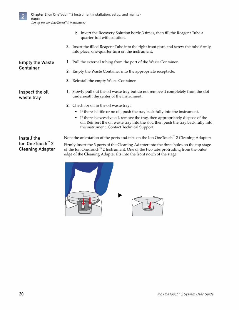
Note the orientation of the ports and tabs on the Ion OneTouch™ 2 Cleaning Adapter:
Firmly insert the 3 ports of the Cleaning Adapter into the three holes on the top stageof the Ion OneTouch™ 2 Instrument. One of the two tabs protruding from the outeredge of the Cleaning Adapter fits into the front notch of the stage:
Empty the WasteContainer
Inspect the oilwaste tray
Install theIon OneTouch™ 2Cleaning Adapter
Chapter 2 Ion OneTouch™ 2 Instrument installation, setup, and mainte-nanceSet up the Ion OneTouch™ 2 Instrument
2
20 Ion OneTouch™ 2 System User Guide

Initialize the instrument
1. On the home screen, touch Options:
2. Touch Initialize:
Initialization takes 10 minutes.
Chapter 2 Ion OneTouch™ 2 Instrument installation, setup, and mainte-nance
Initialize the instrument
2
Ion OneTouch™ 2 System User Guide 21

1. Remove and retain the Ion OneTouch™ Cleaning Adapter. You can reuse theCleaning Adapter one time for the instrument maintenance protocol after thefirst run, but you must appropriately dispose of the used Cleaning Adapter aftermaintenance (see “Ion OneTouch™ 2 Instrument maintenance“ on page 23).
2. Keep all of the disposable components that were used for initialization in place,including the Ion OneTouch™ 2 Amplification Plate, disposable injector andtubing, Ion OneTouch™ Router, and Ion OneTouch™ Recovery Tubes.
IMPORTANT! After the first run on the Ion OneTouch™ 2 Instrument,appropriately dispose of all components as directed.
3. Proceed to “Perform a verification run“.
Perform a verification run
To ensure optimal use of the Ion OneTouch™ 2 System, we recommend first preparingand enriching template-positive ISPs on the system with a control library.
1. Select the control library from the appropriate control kit for your sequencingsystem (see “Required materials and equipment (not provided)“ on page 8).
2. In an Eppendorf LoBind™ tube, dilute 1 µL of control library into 259 µL ofNuclease-free Water. Use 100 µL of the dilution in the amplification solution.
3. Prepare and enrich the template-positive ISPs on the Ion OneTouch™ 2 System asdescribed in your template preparation kit user guide.
4. If you have a Qubit™ 2.0 or 3.0 Fluorometer, determine the percent template-positive ISPs. If not, proceed to step 5.
5. Sequence the enriched ISPs as described in your sequencing guide.
6. After sequencing, review the run report in the Torrent Browser and confirmsuccessful results with the control library.If you have questions about the results, contact technical support.
The instrument is now ready for use.
Complete theset up
Chapter 2 Ion OneTouch™ 2 Instrument installation, setup, and mainte-nancePerform a verification run
2
22 Ion OneTouch™ 2 System User Guide

Ion OneTouch™ 2 Instrument maintenance
Follow the cleaning procedure in this section to clean the Ion OneTouch™ 2Instrument with the Ion OneTouch™ Cleaning Adapter. The cleaning procedure isperformed according to the steps displayed on the instrument after removing theRecovery Tubes.
IMPORTANT! Perform the cleaning procedure after every run. Do not skip thisprocedure.
Note: To set up the Ion OneTouch™ 2 Instrument when switching betweensequencing platforms and/or template preparation kits, see Chapter 5, “Demonstratedprotocol: Switching between older and newer template preparation kits“.
1. Determine the appropriate reagents to use for maintaining the Ion OneTouch™ 2Instrument:
If you are... Then…
Switching to a new templatepreparation kit?
See Chapter 5, “Demonstrated protocol:Switching between older and newer templatepreparation kits“.
Using the same templatepreparation kit?
Proceed to step 2.
2. Check the level of Ion OneTouch™ Oil in the Reagent Tube:a. Ensure that the left Reagent Tube has ³20 mL of oil:
b. If the Reagent Tube has <20 mL of oil, pour oil into the Reagent Tube until itis half-full.
3. Remove and appropriately discard the used Ion OneTouch™ Reaction Filter.Remove the assembly from the instrument by grasping the filter.
Note: The Reaction Tube is filled with Ion OneTouch™ Oil.
4. Keep the Ion OneTouch™ 2 Amplification Plate in the heat block.
Clean theIon OneTouch™ 2Instrument
Chapter 2 Ion OneTouch™ 2 Instrument installation, setup, and mainte-nance
Ion OneTouch™ 2 Instrument maintenance
2
Ion OneTouch™ 2 System User Guide 23
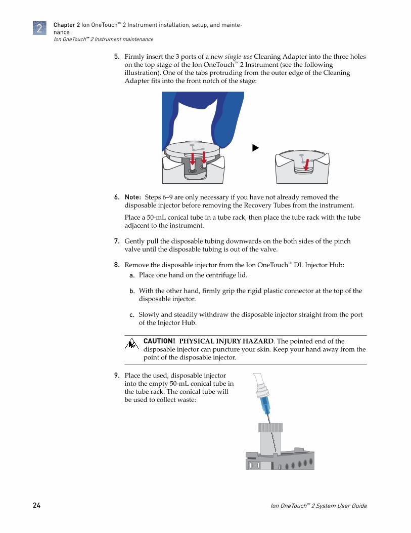
5. Firmly insert the 3 ports of a new single-use Cleaning Adapter into the three holeson the top stage of the Ion OneTouch™ 2 Instrument (see the followingillustration). One of the tabs protruding from the outer edge of the CleaningAdapter fits into the front notch of the stage:
6. Note: Steps 6–9 are only necessary if you have not already removed thedisposable injector before removing the Recovery Tubes from the instrument.
Place a 50-mL conical tube in a tube rack, then place the tube rack with the tubeadjacent to the instrument.
7. Gently pull the disposable tubing downwards on the both sides of the pinchvalve until the disposable tubing is out of the valve.
8. Remove the disposable injector from the Ion OneTouch™ DL Injector Hub:a. Place one hand on the centrifuge lid.
b. With the other hand, firmly grip the rigid plastic connector at the top of thedisposable injector.
c. Slowly and steadily withdraw the disposable injector straight from the portof the Injector Hub.
CAUTION! PHYSICAL INJURY HAZARD. The pointed end of thedisposable injector can puncture your skin. Keep your hand away from thepoint of the disposable injector.
9. Place the used, disposable injectorinto the empty 50-mL conical tube inthe tube rack. The conical tube willbe used to collect waste:
Chapter 2 Ion OneTouch™ 2 Instrument installation, setup, and mainte-nanceIon OneTouch™ 2 Instrument maintenance
2
24 Ion OneTouch™ 2 System User Guide

10. On the home screen of the instrument, touch Clean:
11. Complete each task displayed on the screen, then touch Next. After you touchNext on the last task, the cleaning begins.
12. At the end of the cleaning run, the screen displays "Time Remaining 00:00:00,Cleaning Run Complete". Press Next, then ensure that the task in bold displays:“Remove plate, injector, conical tube, and waste”.
Note: Keep the used Cleaning Adapter on the instrument between runs.
13. Appropriately dispose of the waste in the 50-mL conical tube.
14. Remove and appropriately dispose of the used Amplification Plate, disposableinjector, and tubing from the instrument:
a. Push the handle to open the heat block.
b. Remove the disposable tubing from the Ion OneTouch™ DL Catch.
c. Gently pull back the Amplification Plate from the inlet and outlet holes ofthe instrument.
d. Remove the Amplification Plate from the heat block, and appropriatelydispose of the used Amplification Plate, injector, and tubing.
e. Leave the heat block open.
CAUTION! Hot Surface. Use care when working around this area to avoidbeing burned by hot components.
15. On the instrument touchscreen, touch Open Lid, wait until the lid clicks open,then open the centrifuge lid. Wipe the residue from the centrifuge lid with dryKimwipes™ disposable wipers and close the centrifuge lid.
16. Touch Next to return to the home screen on the instrument.
Chapter 2 Ion OneTouch™ 2 Instrument installation, setup, and mainte-nance
Ion OneTouch™ 2 Instrument maintenance
2
Ion OneTouch™ 2 System User Guide 25

Ion OneTouch™ 2 Instrument decontamination
Before returning the instrument for service, decontaminate it according to theprocedure below.
• Disposable rubber gloves• Safety glasses• Lab coat• Bleach• Water• Paper towels
IMPORTANT! This procedure does not guarantee total decontamination of theIon OneTouch™ 2 Instrument.
1. Wear disposable rubber gloves, safety glasses, and a lab coat.
2. Use a cleaning pad wetted with a solution of 1 part chlorine bleach in 9 partswater (10% bleach solution) to clean all outside surfaces of the Ion OneTouch™ 2Instrument. Use care to avoid getting bleach solution inside the chassis.
3. Dry the surfaces of the Ion OneTouch™ 2 Instrument with paper towels or otherdisposable wipes.
4. Use cotton swabs to clean and dry areas that are difficult to reach.
5. Properly dispose of used cleaning materials to ensure that no one becomesexposed to contaminants.
Download the log files from the Ion OneTouch™ 2 Instrument
Log files capture important information regarding instrument operation and may beused to troubleshoot the instrument.
IMPORTANT! Log files are automatically deleted from the instrument when theinstrument is turned off. To preserve the log files, leave the instrument on until youcan download them.
1. Ensure that the Ion OneTouch™ 2 Instrument is not performing a run.
2. Format a USB flash drive with a FAT32 file system, if necessary (see “Install afirmware update with a USB flash drive“ on page 11). Confirm that the formattedUSB flash drive has no data files on it.
Materials andequipmentrequired
Decontaminatethe instrument
Chapter 2 Ion OneTouch™ 2 Instrument installation, setup, and mainte-nanceIon OneTouch™ 2 Instrument decontamination
2
26 Ion OneTouch™ 2 System User Guide

3. Insert the USB flash drive into the USB port, located on the back of theIon OneTouch™ 2 Instrument:
1
2
3
4
1 Ethernet connection2 USB port3 Power switch (on/off)4 Power socket
4. In the home screen, touch Options, then touch Export Log:
5. In the Export log screen, touch Yes. The log files export to the USB flash driveand the status update displays. After export, the Options screen displays.
6. Remove the USB flash drive from the instrument, then verify on a computer thatthe instrument downloaded the log files to the flash drive. If the files are:
• Downloaded: Proceed to the next step.• Not downloaded: Repeat steps 3–6 until the log files are downloaded.
7. Save the log files to a computer.
Chapter 2 Ion OneTouch™ 2 Instrument installation, setup, and mainte-nance
Download the log files from the Ion OneTouch™ 2 Instrument
2
Ion OneTouch™ 2 System User Guide 27

Ion OneTouch™ ES Instrumentinstallation, setup, and maintenance
IMPORTANT! Ensure that the fuse module for the Ion OneTouch™ ES Instrument isproperly installed, according to 110–120 V or 240 V line voltages. See “Unpack andinstall the Ion OneTouch™ ES Instrument“.
Instrument clearances
Position the instrument so that the front is a minimum of 12 in. (30.5 cm) from thefront of the laboratory bench. Place the instrument at least 40 in. (1 meter) away frommajor sources of electronic noise such as refrigerators or microwaves. For moreinformation, refer to the appropriate site preparation guide specific for yoursequencing system.
Unpack and install the Ion OneTouch™ ES Instrument
For detailed instructions on site preparation and installation of the Ion OneTouch™ ESInstrument, refer to the site preparation and installation requirements in yoursequencing system site preparation guide.
Note: Ensure that the Ion OneTouch™ ES is in a room at an operating temperature of15°C to 25°C (60°F to 77°F).
1. Unpack and install the Ion OneTouch™ ES Instrument in a location different fromthe location used to prepare the amplification solution.
2. Remove the accessories and AC line cords from the box.
3. Place hands under the front and rear of the instrument and lift to removeinstrument from the carton.
IMPORTANT! Do not lift the instrument by holding the syringe located at theback of the instrument.
3
28 Ion OneTouch™ 2 System User Guide

4. Install the AC line voltage fuse module, see page 30 for more information.a. For 120-line voltage: Align the small arrow below the "110–120V" shown on
the fuse module with the white arrow on the power entry module.
220 - 240V 110 - 120V1
1 Arrows aligned
b. For 220-line voltage: Align the small arrow below the "220–240V" shown onthe fuse module with the white arrow on the power entry module.
5. Ensure that the power switch is Off, then plug the power cord into theinstrument.
6. Plug the other end of the power cord into the surge protector or line conditioner.
7. Plug the surge protector or line conditioner into an electrical outlet.
IMPORTANT! The voltage of the electrical outlet must match the voltage of thesurge protector and the selected voltage of the installed AC line voltage fusemodule in the Ion OneTouch™ ES.
Chapter 3 Ion OneTouch™ ES Instrument installation, setup, and main-tenance
Unpack and install the Ion OneTouch™ ES Instrument
3
Ion OneTouch™ 2 System User Guide 29

The fuse module must be installed into the power entry module so that the propervoltage is applied to the instrument.
Line voltage Replacement fuse type
110/120 VAC 375 mA TT (Slow Blow) 1/4" × 1-1/4"
220/240 VAC 160 mA TT (Slow Blow) 5 × 20 mm
1. Turn the power switch to the Off position, then disconnect the power cord fromthe power cable socket.
220 - 240V 110 - 120V4
2
3
1
1 Power entry module2 Power switch3 Power cable socket4 Fuse drawer
2. Insert a small screw driver (or equivalent) into the slot at the top-middle of thefuse drawer, then pry open the fuse drawer.
220 - 240V 110 - 120V
1
2
1 Small screw driver2 Slot for opening fuse drawer
Install the AC linevoltage fusemodule
Chapter 3 Ion OneTouch™ ES Instrument installation, setup, and main-tenanceUnpack and install the Ion OneTouch™ ES Instrument
3
30 Ion OneTouch™ 2 System User Guide
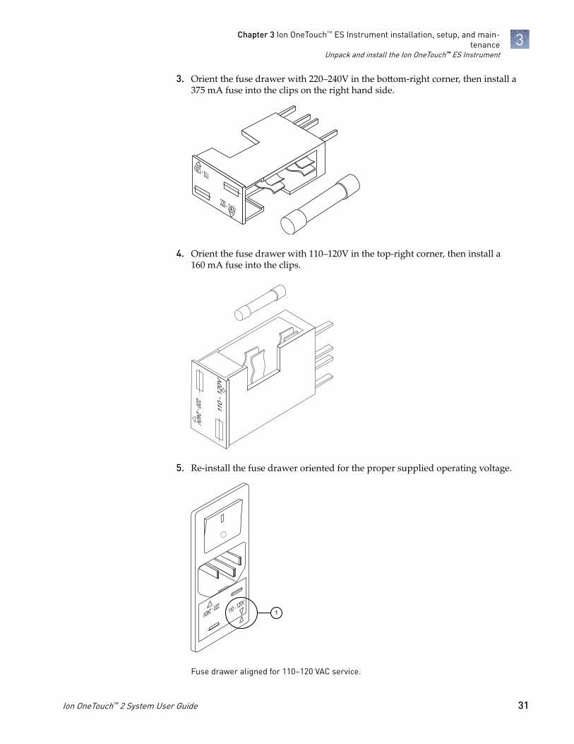
3. Orient the fuse drawer with 220–240V in the bottom-right corner, then install a375 mA fuse into the clips on the right hand side.
220 - 240V
110 - 120V
4. Orient the fuse drawer with 110–120V in the top-right corner, then install a160 mA fuse into the clips.
110
- 120
V
220 - 240V
5. Re-install the fuse drawer oriented for the proper supplied operating voltage.
220 - 240V 110 - 120V1
Fuse drawer aligned for 110–120 VAC service.
Chapter 3 Ion OneTouch™ ES Instrument installation, setup, and main-tenance
Unpack and install the Ion OneTouch™ ES Instrument
3
Ion OneTouch™ 2 System User Guide 31

Set up the OneTouch™ ES Instrument
Before operating the instrument for the first time, you must perform the residualvolume test and calibrate the instrument in both the vertical and horizontal axes.
Provided in your template preparation solutions:
• Nuclease-free Water
Provided with your template preparation supplies:
• 8-well strip
• Eppendorf™ LoRetention Dualfilter Tips (P300)
Provided with the Ion OneTouch™ 2 System (Part no. 4474779):
• Corning Brand 96-Well Strip Ejector (Thermo Fisher Cat. no. 07-200-22), unless8‑well strips are supplied loose and out of the frame
Other Materials and Equipment:
• Elbow fitting for Ion OneTouch™ ES
• 0.2-mL PCR tubes
• Pipettes
• Vortexer
• (Optional) Felt-tipped pen
Ensure that the power switch is turned Off and the AC line voltage fuse module isinstalled in the proper orientation. See “Unpack and install the Ion OneTouch™ ESInstrument“ on page 28.
1. Locate the Tray, Tip Arm, and Tip Loader of the Ion OneTouch™ ES Instrument.
2. Install the Tray:a. Wipe the instrument and the bottom of the Tray with a damp lab wipe to
remove any packaging debris.
b. Place the Tray on the Ion OneTouch™ ES with the calibration shelf on the leftas shown in the following illustration.
Materials requiredfor this procedure
Set up theinstrument
Chapter 3 Ion OneTouch™ ES Instrument installation, setup, and main-tenanceSet up the OneTouch™ ES Instrument
3
32 Ion OneTouch™ 2 System User Guide

c. Push the Tray down firmly so that the Tray fits snugly in the clamps, thenconfirm that the Tray is level:
IMPORTANT! For proper operation of the Ion OneTouch™ ES, the tray mustbe firmly and uniformly seated in the cutout for the tray.
3. Place the Tip Loader in the slot on the left side of the instrument deck:
Chapter 3 Ion OneTouch™ ES Instrument installation, setup, and main-tenance
Set up the OneTouch™ ES Instrument
3
Ion OneTouch™ 2 System User Guide 33

4. Install the supplied elbow fitting and place the Tip Arm in the cradle.a. Insert the male end of the elbow fitting into the female connector on the Tip
Arm, then finger tighten the lock ring on the elbow fitting:
b. Connect the tubing to the elbow fitting on the top of the Tip Arm:
c. Finger-tighten the connectors at both ends of the elbow.
IMPORTANT! Do not twist or coil the tubing.
d. Tilt the Tip Arm back. Align the pins with the round notches in the cradle,then lower the Tip Arm into position. Move the Tip Arm forward into theworking position (see the following illustration):
Note: Ensure that the back/bottom end of the Tip Arm is not resting on topof the thumb screw, causing the Tip Arm to tilt forward. Do not adjust theangle of the arm unless you need to calibrate the instrument.
5. Turn the power switch On. (Optional) Leave the instrument On continuouslyduring daily and weekly use.
Chapter 3 Ion OneTouch™ ES Instrument installation, setup, and main-tenanceSet up the OneTouch™ ES Instrument
3
34 Ion OneTouch™ 2 System User Guide

Install a new pipette tip on the tip arm
Before every calibration, residual volume test, or enrichment performed on theIon OneTouch™ ES Instrument, install a new Eppendorf™ LoRetention Dualfilter P300pipette tip.
1. Place a new tip in the Tip Loader. Remove the Tip Arm from the cradle and alignthe metal fitting of the Tip Arm with the tip.
2. Keeping the fitting on the Tip Arm vertical, firmly press the Tip Arm down ontothe new tip until the Tip Arm meets the Tip Loader. Hold the Tip Arm to the TipLoader for ~1 second to ensure proper installation of the tip.
3. Lift the Tip Arm straight up to pull the installed tip from the Tip Loader tube.
4. Return the Tip Arm to the cradle (see the following illustration).a. Tilt the Tip Arm back (below left) and align the pins with the round notches
in the cradle (below middle).
b. Lower the Tip Arm into position (below center).
c. Move the Tip Arm forward into the working position (below right).
Chapter 3 Ion OneTouch™ ES Instrument installation, setup, and main-tenance
Set up the OneTouch™ ES Instrument
3
Ion OneTouch™ 2 System User Guide 35
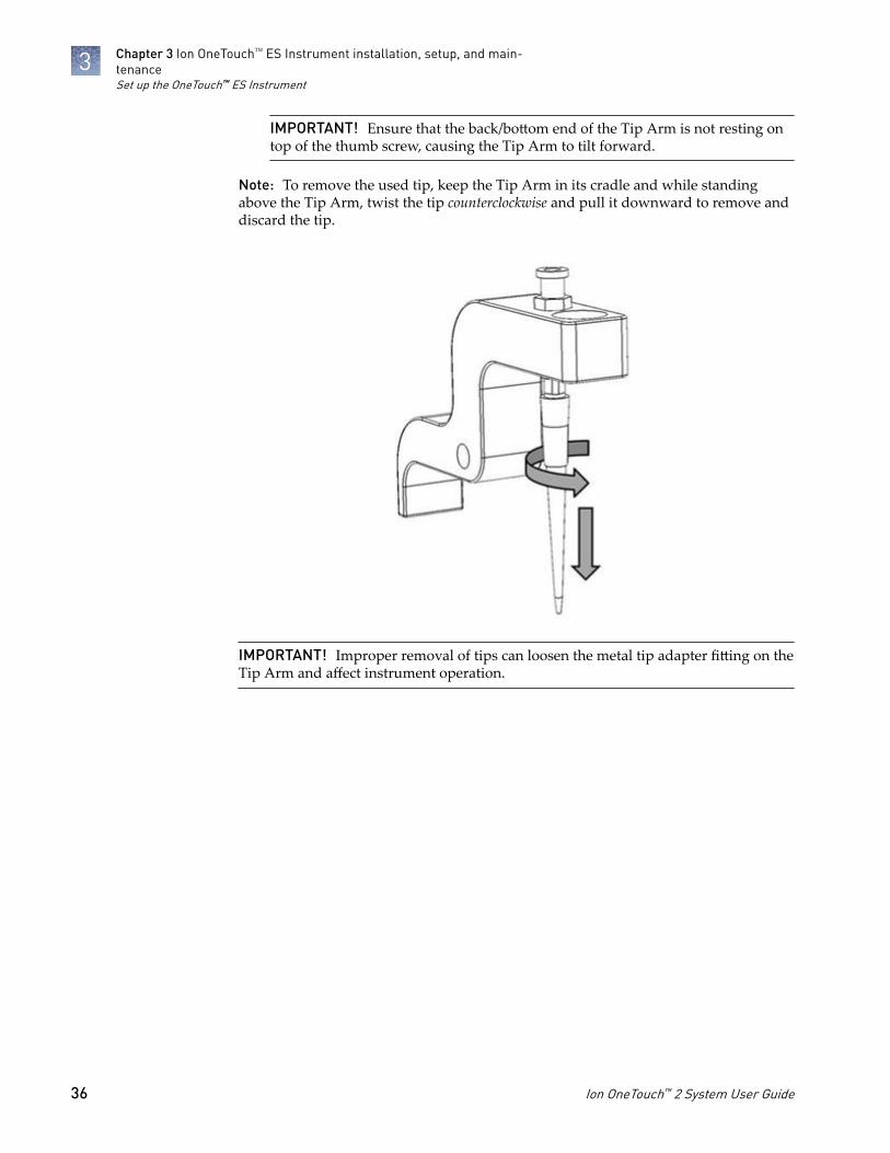
IMPORTANT! Ensure that the back/bottom end of the Tip Arm is not resting ontop of the thumb screw, causing the Tip Arm to tilt forward.
Note: To remove the used tip, keep the Tip Arm in its cradle and while standingabove the Tip Arm, twist the tip counterclockwise and pull it downward to remove anddiscard the tip.
IMPORTANT! Improper removal of tips can loosen the metal tip adapter fitting on theTip Arm and affect instrument operation.
Chapter 3 Ion OneTouch™ ES Instrument installation, setup, and main-tenanceSet up the OneTouch™ ES Instrument
3
36 Ion OneTouch™ 2 System User Guide

Ion OneTouch™ ES Instrument calibration
Perform horizontal and vertical calibrations so that during operation the tip isoptimally positioned in the well (see the following illustration) of the 8-well strip:
Note that the 8-well strip is always tilted at a fixed 10-degree angle in the slot. Thepipette tip is vertical. When the tip is aligned properly during calibration so that it isin line with the notch in the calibration shelf, the tip touches the bottom of the wellduring the run, close to the front bottom edge of the well.
IMPORTANT! If you use more than one Ion OneTouch™ ES Instrument, do not switchTrays or Tip Arms between instruments. Each Tray and Tip Arm is calibrated with aparticular instrument. To track the Tray and Tip Arm, each component has a printedlabel with the matching serial number of the instrument.
1. Install a new tip on the tip arm. See page 35.
2. Power Off the instrument, then wait 3 seconds.
3. While holding down Vert. Adjust, power On the instrument to restore thefactory default settings.
4. Power Off the instrument.
5. While holding down Select/Calibrate, power the instrument On. Keep holdingdown Select/Calibrate until “P1” is displayed.
6. Press Select/Calibrate for ~3 seconds until the instrument beeps 2 times and“CAL” is displayed to put the instrument into calibration mode.
Note: The instrument will cycle through several values before “CAL” isdisplayed.
7. Press Vert. Adjust. The instrument displays “ASP” (Aspirate or z-bottomposition).
Calibrate thevertical axis
Chapter 3 Ion OneTouch™ ES Instrument installation, setup, and main-tenance
Ion OneTouch™ ES Instrument calibration
3
Ion OneTouch™ 2 System User Guide 37

8. Press Start/Stop. The Tip Arm lowers to bring the tip near the notch in thecalibration shelf on the left side of the Tray.
9. Adjust if needed the position of the bottom of the pipette tip:
a. To adjust the alignment of the tip with the slot, turn the thumbscrew at theback of the Tip Arm.
b. To adjust the height of the tip, press the (minus) button repeatedly untilthe tip touches the shelf. Press the (minus) button eight more times tolower the tip further. This will account for variations in tip lengths andinstallation.
Note: It is better to have the ASP (aspiration) height be too low than toohigh.
10. Press Start/Stop, then wait for the Tip Arm to stop moving and for “P1” todisplay.
Chapter 3 Ion OneTouch™ ES Instrument installation, setup, and main-tenanceIon OneTouch™ ES Instrument calibration
3
38 Ion OneTouch™ 2 System User Guide

1. Press Select/Calibrate for ~3 seconds until the instrument beeps 2 times and“CAL” is displayed.
Note: The instrument will cycle through several values before “CAL” isdisplayed.
2. Press Horiz. Adjust. Instrument displays “FLA”, then press Start/Stop.
3. Place an empty 8-well strip in the slot in the Tray, with the square tab on the left.
4. Push the 8-well strip as far to the left in the slot as possible.
5. Observe the position of the 8-well strip relative to the position of the tip. Whenproperly calibrated, the 8-well strip is ≤1 mm of touching but not pushing on thetip. To clearly see the relationship between the pipette tip, calibration shelf, andnotch during calibration, mark each of them with a felt-tip pen:
6. Adjust the horizontal position of the Tip Arm so that the tip just touches the lefttab of the 8-well strip when the 8-well strip is pushed to the far left of the slot inthe Tray:
a. Apply slight pressure to keep the 8-well strip to the far left.
b. Press the (plus) button repeatedly until the tip touches the 8-well strip.Each press of the (plus) key moves the Tip Arm to the right by~0.002 inches (~50 µm), which may be difficult to detect.
7. Press Start/Stop to save the setting and for “P1” to display.
8. Power the instrument Off, wait >3 seconds, then power the instrument On toreturn to normal operating mode.
9. Perform a residual volume test (see “Perform a residual volume test“ onpage 40).
Calibrate thehorizontal axis
Chapter 3 Ion OneTouch™ ES Instrument installation, setup, and main-tenance
Ion OneTouch™ ES Instrument calibration
3
Ion OneTouch™ 2 System User Guide 39

Perform a residual volume test
If the condition is... Then...
First use of the instrument andduring monthly maintenance
Perform a residual volume test (see instructionsbelow).
Routine use and residual volumein Well 1 and Well 8 is >5.0 µL
Routine use and residual volumein Well 1 and Well 8 is £5.0 µL
Operate the instrument without performing theresidual volume test.
IMPORTANT! Before running the residual volume test, carefully read and familiarizeyourself with this procedure. During the test, confirm that the pipette tip is centeredbetween the sides of the wells when moving in or out of a well.
1. Pipet 80 µL water or Ion OneTouch™ Wash solution into the second well (Well 2)from the square-tabbed end of the 8-well strip.
3
1
2
1 Square-shaped tab2 Well 23 Rounded tab
Chapter 3 Ion OneTouch™ ES Instrument installation, setup, and main-tenancePerform a residual volume test
3
40 Ion OneTouch™ 2 System User Guide

2. Load the 8-well strip into the slot of the Tray so that the square-tabbed end is tothe left and the 8-well strip is pushed all the way to the right until it touches theend of the slot.
3. Turn the instrument On, then wait for the instrument to initialize. The Tip Armperforms a series of movements and returns to the home position (~5 seconds),then “rdy” is displayed on the instrument screen.
4. Press Start/Stop.
5. Wait for the instrument to aspirate the solution from Well 2 and completelyremove the tip from Well 2, then manually push the 8-well strip to the left so thatWell 4 is positioned directly under the Tip Arm.
6. Wait for the instrument to dispense the tip contents into Well 4.
7. Press Start/Stop to stop the test run, then press Start/Stop again to return the TipArm to the home position.
8. Using a P10 pipette, aspirate the entire residual water or Ion OneTouch™ WashSolution from well 2, then estimate the residual volume.
9. Remove and discard the used pipette tip and 8-well strip.
Chapter 3 Ion OneTouch™ ES Instrument installation, setup, and main-tenance
Perform a residual volume test
3
Ion OneTouch™ 2 System User Guide 41

10. After performing the residual volume test, take one or more of the followingactions:
Observation Possible cause Recommended actions
Residual volume in Well 2is £5 µL
— No action is necessary.
Residual volume in Well 2is >5 µL
The tip height is too highduring aspiration.
Restore defaults, thencalibrate the instrument(see “Ion OneTouch™ ESInstrument calibration“ onpage 37).
Aspiration is irregular This instrument out ofcalibration.
Restore defaults, thencalibrate the instrument(see “Ion OneTouch™ ESInstrument calibration“ onpage 37).
The 8-well strip lifts asthe tip rises to the top ofthe well
The tip is angled too farforward or the tip height isset too low.
Verify that the tip isvertical and positioneddirectly over the notch inthe calibration shelf. If thetip is positioned correctly.Restore defaults, thencalibrate the instrument(see “Ion OneTouch™ ESInstrument calibration“ onpage 37).
Chapter 3 Ion OneTouch™ ES Instrument installation, setup, and main-tenancePerform a residual volume test
3
42 Ion OneTouch™ 2 System User Guide
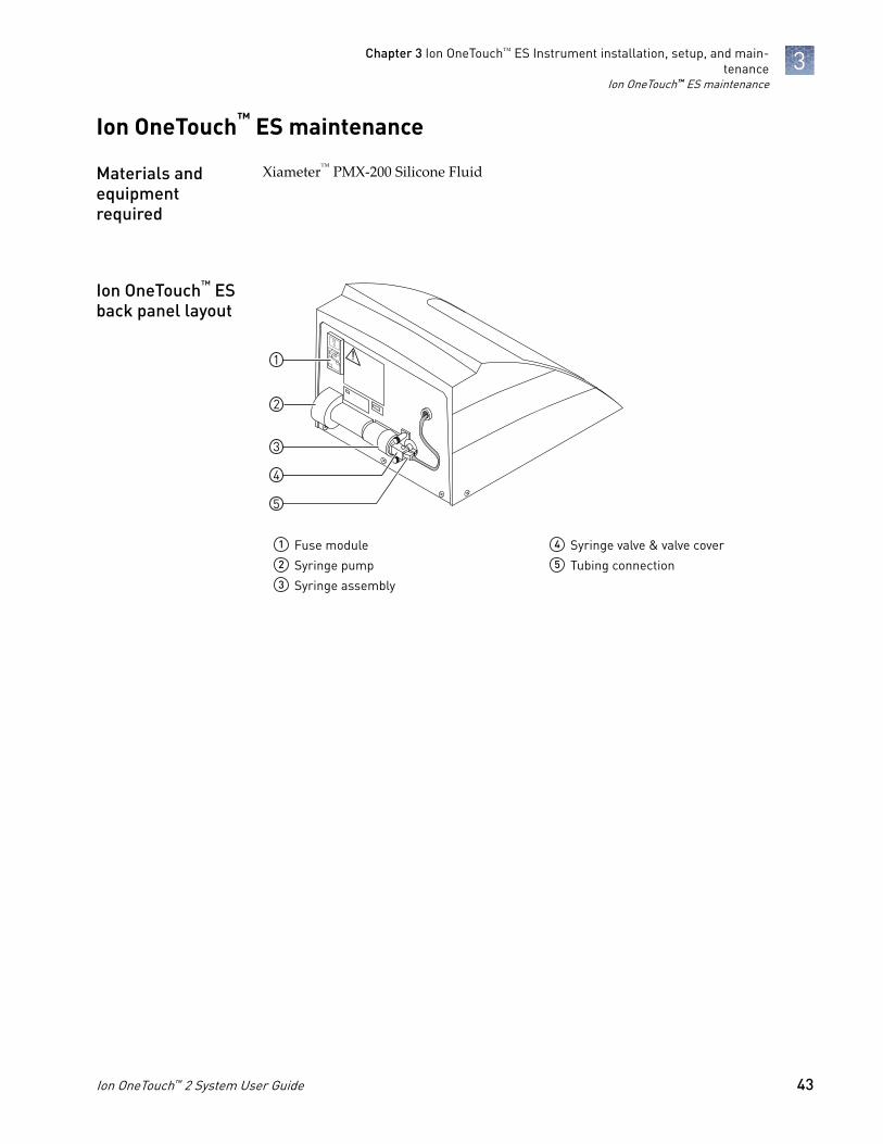
Ion OneTouch™ ES maintenance
Xiameter™ PMX-200 Silicone Fluid
5
3
4
1
2
1 Fuse module2 Syringe pump3 Syringe assembly
4 Syringe valve & valve cover5 Tubing connection
Materials andequipmentrequired
Ion OneTouch™ ESback panel layout
Chapter 3 Ion OneTouch™ ES Instrument installation, setup, and main-tenance
Ion OneTouch™ ES maintenance
3
Ion OneTouch™ 2 System User Guide 43
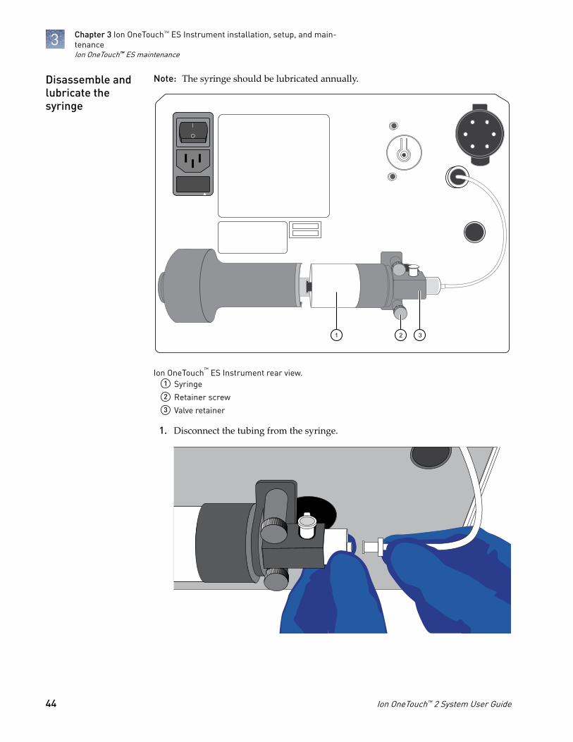
Note: The syringe should be lubricated annually.
1 2 3
Ion OneTouch™ ES Instrument rear view.1 Syringe2 Retainer screw3 Valve retainer
1. Disconnect the tubing from the syringe.
Disassemble andlubricate thesyringe
Chapter 3 Ion OneTouch™ ES Instrument installation, setup, and main-tenanceIon OneTouch™ ES maintenance
3
44 Ion OneTouch™ 2 System User Guide

2. Remove the 2 retainer screws.
3. Remove the valve retainer.
Chapter 3 Ion OneTouch™ ES Instrument installation, setup, and main-tenance
Ion OneTouch™ ES maintenance
3
Ion OneTouch™ 2 System User Guide 45

4. Pull the syringe body toward you to remove from the instrument.
5. Remove the plunger from the syringe body.
Chapter 3 Ion OneTouch™ ES Instrument installation, setup, and main-tenanceIon OneTouch™ ES maintenance
3
46 Ion OneTouch™ 2 System User Guide

6. Apply a thin layer of Xiameter™ PMX-200 Silicone Fluid evenly to the inside ofthe syringe body.
1. Push the plunger all the way into the syringe body, then pull back outapproximately ¼ inch.
2. Engage the plunger with its mate end.
Reassemble thesyringe
Chapter 3 Ion OneTouch™ ES Instrument installation, setup, and main-tenance
Ion OneTouch™ ES maintenance
3
Ion OneTouch™ 2 System User Guide 47

3. Insert the valve into its docking position.
4. Replace the retainer and the 2 retainer screws (finger-tighten).
5. Reconnect the tubing.
Ion OneTouch™ ES decontamination
Before returning the instrument for service, decontaminate it according to theprocedure below.
• Disposable rubber gloves• Safety glasses• Lab coat• Bleach• Water• Paper towels
IMPORTANT! This procedure does not guarantee total decontamination of theIon OneTouch™ ES.
Wear disposable rubber gloves, safety glasses, and a lab coat.
1. Wipe all outside surfaces of the Ion OneTouch™ ES with 10% bleach solution.Avoid getting bleach solution inside the chassis.
2. Dry the surfaces of the Ion OneTouch™ ES with paper towels or other disposablewipes.
3. Use cotton swabs to clean and dry areas that are difficult to reach.
4. Properly dispose of used cleaning materials.
Materials andequipmentrequired
Decontaminatethe instrument
Chapter 3 Ion OneTouch™ ES Instrument installation, setup, and main-tenanceIon OneTouch™ ES decontamination
3
48 Ion OneTouch™ 2 System User Guide
Set up and test the Ion Chip™
Minifuge
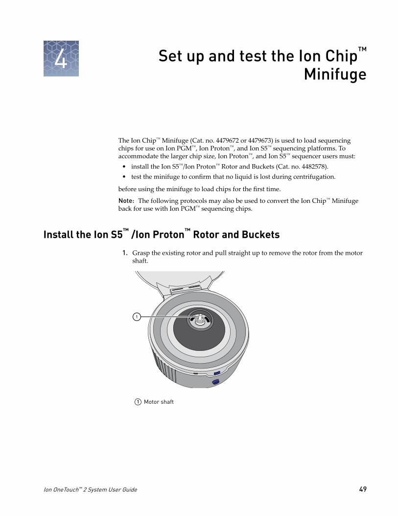
The Ion Chip™ Minifuge (Cat. no. 4479672 or 4479673) is used to load sequencingchips for use on Ion PGM™, Ion Proton™, and Ion S5™ sequencing platforms. Toaccommodate the larger chip size, Ion Proton™, and Ion S5™ sequencer users must:
• install the Ion S5™/Ion Proton™ Rotor and Buckets (Cat. no. 4482578).• test the minifuge to confirm that no liquid is lost during centrifugation.
before using the minifuge to load chips for the first time.
Note: The following protocols may also be used to convert the Ion Chip™ Minifugeback for use with Ion PGM™ sequencing chips.
Install the Ion S5™ /Ion Proton™ Rotor and Buckets
1. Grasp the existing rotor and pull straight up to remove the rotor from the motorshaft.
1
1 Motor shaft
4
Ion OneTouch™ 2 System User Guide 49

2. Press the Ion S5™/Ion Proton™ Rotor down onto the motor shaft to install.
1
1 Insert motor shaft here
3. Tighten the set screw (arrow) with a 1.5-mm hex wrench.
4. Install the two buckets. Position the buckets with the larger semi-circular cut-outsfacing out, and ensure that the buckets hang freely.
1
1 Correct orientation2 Incorrect orientation
2
Chapter 4 Set up and test the Ion Chip™ MinifugeInstall the Ion S5™ /Ion Proton™ Rotor and Buckets4
50 Ion OneTouch™ 2 System User Guide

Test the minifuge
1. Prepare two previously-used chips:a. Inject 100 µL of isopropanol two times into the loading port of each chip.
After each injection, remove the expelled liquid from the opposite port.
Note: Use 50 µL volume of isopropanol if testing Ion PGM™ sequencingchips.
b. Aspirate the remaining isopropanol from the flow cells for 5–10 seconds.Confirm that the chips are dry.
Note: To aspirate the isopropanol, attach a P200 pipette tip to a vacuumline, then place the pipette tip in the chip loading port.
2. Place the two chips prepared in step 1 in the centrifuge buckets, with the chipnotch pointing out. Add 55 µL of nuclease-free water to each chip loading well(do not inject into the chip loading port).
Note: Use 35 µL volume of nuclease-free water if testing Ion PGM™ sequencingchips.
1
1
1 Chip notch
Chapter 4 Set up and test the Ion Chip™ MinifugeTest the minifuge 4
Ion OneTouch™ 2 System User Guide 51
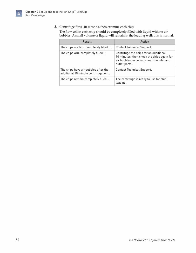
3. Centrifuge for 5–10 seconds, then examine each chip.The flow cell in each chip should be completely filled with liquid with no airbubbles. A small volume of liquid will remain in the loading well; this is normal.
Result Action
The chips are NOT completely filled... Contact Technical Support.
The chips ARE completely filled... Centrifuge the chips for an additional10 minutes, then check the chips again forair bubbles, especially near the inlet andoutlet ports.
The chips have air bubbles after theadditional 10 minute centrifugation...
Contact Technical Support.
The chips remain completely filled... The centrifuge is ready to use for chiploading.
Chapter 4 Set up and test the Ion Chip™ MinifugeTest the minifuge4
52 Ion OneTouch™ 2 System User Guide
Demonstrated protocol: Switchingbetween older and newer template
preparation kits
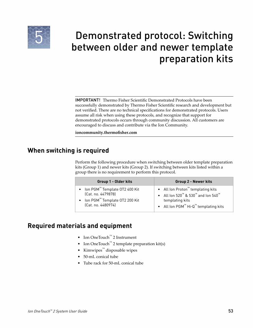
IMPORTANT! Thermo Fisher Scientific Demonstrated Protocols have beensuccessfully demonstrated by Thermo Fisher Scientific research and development butnot verified. There are no technical specifications for demonstrated protocols. Usersassume all risk when using these protocols, and recognize that support fordemonstrated protocols occurs through community discussion. All customers areencouraged to discuss and contribute via the Ion Community.
ioncommunity.thermofisher.com
When switching is required
Perform the following procedure when switching between older template preparationkits (Group 1) and newer kits (Group 2). If switching between kits listed within agroup there is no requirement to perform this protocol.
Group 1 - Older kits Group 2 - Newer kits
• Ion PGM™ Template OT2 400 Kit(Cat. no. 4479878)
• Ion PGM™ Template OT2 200 Kit(Cat. no. 4480974)
• All Ion Proton™ templating kits
• All Ion 520™ & 530™ and Ion 540™
templating kits
• All Ion PGM™ Hi‑Q™ templating kits
Required materials and equipment
• Ion OneTouch™ 2 Instrument• Ion OneTouch™ 2 template preparation kit(s)• Kimwipes™ disposable wipes• 50-mL conical tube• Tube rack for 50-mL conical tube
5
Ion OneTouch™ 2 System User Guide 53
Before you begin
1. Complete the current run on the Ion OneTouch™ 2 System.
2. Process the ISPs according to the template preparation user guide currently inuse.
IMPORTANT! Save the following for re-use during the instrument initialization(see “Initialize the Ion OneTouch™ 2 Instrument“ on page 55):· Both Ion OneTouch™ Recovery Tubes· Ion OneTouch™ Router· Ion OneTouch™ 2 Amplification Plate
3. Obtain the appropriate kit for preparation of templated ISPs for the sequencingsystem you are switching to. The Ion OneTouch™ Oil and Ion OneTouch™
Recovery Solution in the kit are used to clean the instrument.
Clean the Ion OneTouch™ 2 Instrument after the last run
IMPORTANT! Ensure that the latest firmware is installed on the Ion OneTouch™ 2Instrument. See “Checking and updating the firmware on the Ion OneTouch™ 2Instrument“ on page 11. The latest firmware for the Ion OneTouch™ 2 Instrument isrequired to perform the cleaning procedure with the Ion OneTouch™ 2 CleaningAdapter (refer to the Options screen on the instrument display).
Note: Visually inspect the rotor assembly and casing periodically to ensure there areno cracks or signs of other physical damage.
1. Discard or keep the following materials from the last run:
Discard Keep
Reaction Filter Assembly Both Ion OneTouch™ Reagent Tubes(Store for re-use with the kit.)
Ion OneTouch™ Oil Both Ion OneTouch™ Sippers (Store forre-use with the kit.)
Ion OneTouch™ Recovery Solution Ion OneTouch™ 2 Amplification Plate(Store clamped in the heat block.)
2. Install the materials and solutions from the appropriate template preparation kityou are switching to:
• 2 Ion OneTouch™ Sippers• Ion OneTouch™ Reagent Tube filled half-full with Ion OneTouch™ Oil• Ion OneTouch™ Reagent Tube filled a quarter-full with Ion OneTouch™
Recovery Solution
3. Empty the waste container.
Chapter 5 Demonstrated protocol: Switching between older and newertemplate preparation kitsBefore you begin
5
54 Ion OneTouch™ 2 System User Guide

4. Place a 50-mL conical tube in a tube rack, then place the tube rack adjacent to theinstrument.
5. Firmly insert the 3 ports of a single-use Ion OneTouch™ Cleaning Adapter into thethree holes (see page 20) on the top stage of the Ion OneTouch™ 2 Instrument.Ensure the tab protruding from the cleaning adapter fits into the front notch ofthe stage.
6. Gently pull the disposable tubing downwards on both sides of the pinch valveuntil the disposable tubing is out of the valve.
7. Remove the disposable injector from the Ion OneTouch™ DL Injector Hub:a. Place one hand on the centrifuge lid.
b. With the other hand, firmly grip the rigid plastic connector at the top of thedisposable injector.
c. Slowly and steadily withdraw the disposable injector straight from the portof the Injector Hub.
CAUTION! PHYSICAL INJURY HAZARD. The pointed end of thedisposable injector can puncture your skin. Keep your hand awayfrom the point of the injector.
8. Place the used, disposable injector into the empty 50-mL conical tube in the tuberack. The conical tube will be used for waste.
9. In the Ion OneTouch™ 2 Instrument home screen, touch Clean.
10. Follow the on-screen prompts, touch Next after each. After you touch Next onthe last task the cleaning begins.
11. Ensure that the task "Remove plate, injector, conical tube, and waste" displaysat the end of the cleaning run.
IMPORTANT! Keep the used Ion OneTouch™ 2 Amplification Plate andIon OneTouch™ 2 Cleaning Adapter on the instrument to use for initialization ofthe instrument. Keep the disposable injector in the 50-mL conical tube to collectwaste.
Initialize the Ion OneTouch™ 2 Instrument
1. Ensure that the used Ion OneTouch™ 2 Amplification Plate and Ion OneTouch™ 2Cleaning Adapter are on the instrument. Keep the disposable injector inthe 50-mL conical tube.
2. In the instrument display, touch Open Lid, then open the centrifuge lid.
IMPORTANT! Do not lift the lid by the tubing attached to the Ion OneTouch™ DLInjector Hub. Do not force the lid open.
Chapter 5 Demonstrated protocol: Switching between older and newertemplate preparation kits
Initialize the Ion OneTouch™ 2 Instrument
5
Ion OneTouch™ 2 System User Guide 55
3. Insert a used Ion OneTouch™ Recovery Tube into each of the slots in thecentrifuge.
4. Pinch the sides of the used Ion OneTouch™ Recovery Router then push the routerdown into the center slot of the centrifuge so that it is seated flat and secure inthe center of the rotor.
Note: The Ion OneTouch™ Recovery Router is intentionally offset from theIon OneTouch™ Recovery Tubes.
5. In the home screen, touch Options.
6. In the Options screen, touch Initialize, then touch Next until initialization of theinstrument begins. Initialization takes ~10 minutes.
IMPORTANT! For this initialization after cleaning the instrument, do not installthe disposable injector in the Ion OneTouch™ DL Injector Hub. Keep thedisposable injector in the 50-mL conical tube.
Set up the Ion OneTouch™ 2 Instrument with the appropriate kit
1. After initialization, remove and appropriately discard the following from theinstrument:
• Ion OneTouch™ 2 Cleaning Adapter• Ion OneTouch™ 2 Amplification Plate, disposable tubing, and injector• Both Ion OneTouch™ Recovery Tubes• Ion OneTouch™ Router
2. In the instrument display, touch Open Lid, wait until the lid opens, then lift andhold the side of the centrifuge lid.
IMPORTANT! Do not lift the lid by the tubing attached to the Ion OneTouch™ DLInjector Hub. Do not force the lid open.
3. Insert two new Ion OneTouch™ Recovery Tubes from the appropriate templatepreparation kit into the slots of the centrifuge.
4. Pinch the sides of the new Ion OneTouch™ Recovery Router then push the routerdown into the center slot of the centrifuge so that it is seated flat and secure inthe center of the rotor.
5. Insert a new Ion OneTouch™ Amplification Plate from the appropriate templatepreparation kit.
6. Pull the handle to close the heat block.
Chapter 5 Demonstrated protocol: Switching between older and newertemplate preparation kitsSet up the Ion OneTouch™ 2 Instrument with the appropriate kit
5
56 Ion OneTouch™ 2 System User Guide

7. Close the centrifuge lid, and thread the disposable tubing through the catch andpinch valve, then insert the disposable injector in the Ion OneTouch™ DL InjectorHub.
8. Refer to the appropriate template preparation kit user guide to prepare andinstall the amplification solution. Complete the remaining tasks to run thesample on the Ion OneTouch™ 2 Instrument to prepare template-positive ISPs forsequencing.
Chapter 5 Demonstrated protocol: Switching between older and newertemplate preparation kits
Set up the Ion OneTouch™ 2 Instrument with the appropriate kit
5
Ion OneTouch™ 2 System User Guide 57

Troubleshooting
Ion OneTouch™ 2 Instrument
Observation Possible cause Recommended action
Firmware does not update orthe status update screen doesnot display £10 seconds
Firmware not updating on theinstrument
1. Power the instrument OFF then ON.2. Ensure that the USB flash drive is FAT32-
formatted and that the file is in the rootdirectory.
3. Remove then reinsert the USB flash driveimmediately after the main menu displays.
4. Repeat steps 1–3 as needed.
Disposable injector remainsin "down" position in theIon OneTouch™ DL InjectorHub
• Reagent build-up
• New part
1. Gently pull from the top of the disposableinjector until the disposable injector justreturns to the “up” position in the InjectorHub (see “Install the disposable injector“ onpage 18).
2. Briefly press then release the spring-loadedtop of the Injector Hub 5-10 times at the pointindicated by the arrow (see illustration in “Install the disposable injector“ on page 18).You should hear a click.
3. If the Injector Hub remains in the “down”position, repeat step 2 once (up to 10 moreclicks).
Note: If the Injector Hub still does not movefreely and click up into place, then contactTechnical Support.
Recovery tubes filled with gelafter run
Note: This observation andrecommended action pertainonly to template preparationkits that require the use ofIon OneTouch™ BreakingSolution.
Breaking Solution was notadded to Recovery Tubesprior to start of run.
1. Add 150 μL Ion OneTouch™ Breaking Solutionto each Recovery Tube.
2. Seal the Recovery Tubes with Parafilm® Mfilm and vigorously invert and vortex thetubes for 10 seconds to break the emulsion.
3. Refer to the user guide of the templatepreparation kit in use and follow theprocedure to "Recover the template-positiveISPs". Alternatively, transfer samples to two1.5-mL tubes and spin in an Eppendorf™
centrifuge for 10 minutes at 15,500 × g topellet the ISPs.
4. Refer to the user guide of the templatepreparation kit in use and proceed to "Washthe template-positive ISPs". Perform the ISPwash in 1 mL nuclease-free water twice.
A
58 Ion OneTouch™ 2 System User Guide
Observation Possible cause Recommended action
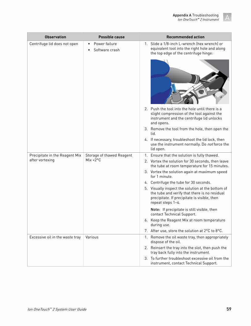
Centrifuge lid does not open • Power failure
• Software crash
1. Slide a 1/8-inch L-wrench (hex wrench) orequivalent tool into the right hole and alongthe top edge of the centrifuge hinge:
2. Push the tool into the hole until there is aslight compression of the tool against theinstrument and the centrifuge lid unlocksand opens.
3. Remove the tool from the hole, then open thelid.
4. If necessary, troubleshoot the lid lock, thenuse the instrument normally. Do not force thelid open.
Precipitate in the Reagent Mixafter vortexing
Storage of thawed ReagentMix <2°C
1. Ensure that the solution is fully thawed.2. Vortex the solution for 30 seconds, then leave
the tube at room temperature for 15 minutes.3. Vortex the solution again at maximum speed
for 1 minute.4. Centrifuge the tube for 30 seconds.5. Visually inspect the solution at the bottom of
the tube and verify that there is no residualprecipitate. If precipitate is visible, thenrepeat steps 1–4.
Note: If precipitate is still visible, thencontact Technical Support.
6. Keep the Reagent Mix at room temperatureduring use.
7. After use, store the solution at 2°C to 8°C.
Excessive oil in the waste tray Various 1. Remove the oil waste tray, then appropriatelydispose of the oil.
2. Reinsert the tray into the slot, then push thetray back fully into the instrument.
3. To further troubleshoot excessive oil from theinstrument, contact Technical Support.
Appendix A TroubleshootingIon OneTouch™ 2 Instrument A
Ion OneTouch™ 2 System User Guide 59

Ion OneTouch™ ES
For Ion OneTouch™ ES vertical and horizontal axis calibration and residual volumetest procedures, refer to Chapter 3 of the Ion OneTouch™ 2 System User Guide (Pub. no.MAN0014388).
Observation Possible cause Recommended action
Excessive foaming occurs. • Instrument is improperlycalibrated resulting ininadequate volume in oneor more wells.
• Fitting is loose.
• Pipette tip is cracked.
1. Use the recommended volumes for allwells.
2. Ensure that fittings are tight, especially atthe elbow fitting, and the pipette tip is notcracked.
3. If necessary, perform the residual volumetest. If the residual volume test fails, thencalibrate the instrument.
Brown pellet is present incentrifuged tube of enrichedISPs.
Residual Dynabeads™ MyOne™
Streptavidin C1 Beads arepresent.
1. Pipet the suspension with the brownpellet up and down 10 times to resuspendthe pellet.
2. Place the 0.2-mL PCR tube against amagnet such as a DynaMag™-2 magnetfor 4 minutes.
3. Transfer the supernatant with theenriched ISPs to a new 0.2-mL PCR tubewithout disturbing the pellet ofDynabeads™ MyOne™ Streptavidin C1Beads.
4. Sequence or store the enriched ISPs.
Appendix A TroubleshootingIon OneTouch™ ESA
60 Ion OneTouch™ 2 System User Guide
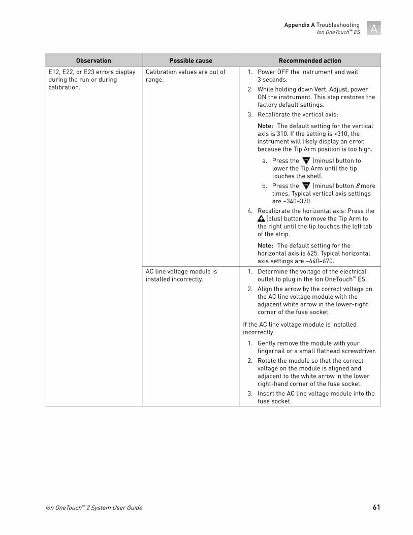
Observation Possible cause Recommended action
E12, E22, or E23 errors displayduring the run or duringcalibration.
Calibration values are out ofrange.
1. Power OFF the instrument and wait3 seconds.
2. While holding down Vert. Adjust, powerON the instrument. This step restores thefactory default settings.
3. Recalibrate the vertical axis:
Note: The default setting for the verticalaxis is 310. If the setting is <310, theinstrument will likely display an error,because the Tip Arm position is too high.
a. Press the (minus) button tolower the Tip Arm until the tiptouches the shelf.
b. Press the (minus) button 8 moretimes. Typical vertical axis settingsare ~340–370.
4. Recalibrate the horizontal axis: Press the (plus) button to move the Tip Arm to
the right until the tip touches the left tabof the strip.
Note: The default setting for thehorizontal axis is 625. Typical horizontalaxis settings are ~640–670.
AC line voltage module isinstalled incorrectly.
1. Determine the voltage of the electricaloutlet to plug in the Ion OneTouch™ ES.
2. Align the arrow by the correct voltage onthe AC line voltage module with theadjacent white arrow in the lower-rightcorner of the fuse socket.
If the AC line voltage module is installedincorrectly:
1. Gently remove the module with yourfingernail or a small flathead screwdriver.
2. Rotate the module so that the correctvoltage on the module is aligned andadjacent to the white arrow in the lowerright-hand corner of the fuse socket.
3. Insert the AC line voltage module into thefuse socket.
Appendix A TroubleshootingIon OneTouch™ ES A
Ion OneTouch™ 2 System User Guide 61

Observation Possible cause Recommended action
E12 or E22 error is displayedwhen the unit is initializing.
• Fuse is installedincorrectly.
• Unit is below operatingtemperature.
• Program or calibrationsetting is bad,or
• Tip Arm is not moving.
1. Ensure that the fuse module is installedcorrectly and that the unit is at itsrecommended operating temperature.
2. Reboot the instrument: Power OFF theinstrument, wait 3 seconds, then powerON the instrument.
3. If the error persists, restore the factorydefaults, then re-calibrate theinstrument:
a. Power OFF the instrument and wait3 seconds.
b. While holding down Vert. Adjust,power ON the instrument. This steprestores the factory default settings.
c. Repeat 3a–3b as needed to restorethe factory defaults.
d. Calibrate the vertical and horizontalaxes.
Either of the following:
• E12 or E22 errors aredisplayed.
• Tip Arm does not move ormoves slightly.
AC line voltage module isinstalled incorrectly.
1. Determine the voltage of the electricaloutlet serving the Ion OneTouch™ ES.
2. Align the arrow by the correct voltage onthe AC line voltage fuse module with theadjacent white arrow in the lower-rightcorner of the fuse socket.
If the AC line voltage fuse module is installedincorrectly:
1. Gently remove the module with yourfingernail or a small flathead screwdriver.
2. Rotate the module so that the correctvoltage on the module is aligned andadjacent to the white arrow in the lowerright-hand corner of the fuse socket.
3. Insert the AC line voltage fuse moduleinto the fuse socket.
Instrument is not at therecommended operatingtemperature
Ensure that the Ion OneTouch™ ES is at anoperating temperature of 60°F to 77°F (15°C to25°C).
Solution overflows during run. Reagent volumes areoverloaded.
Repeat with reagent volumes described inenrichment procedure.
Tip is causing 8-well strip to liftout of tray slot during run.
Tip is not aligned vertically. Perform the vertical calibration procedure.
Percent template-positive ISPsafter enrichment is <50% asmeasured by flow cytometry.
Multiple causes are possible. Contact Technical Support.
Appendix A TroubleshootingIon OneTouch™ ESA
62 Ion OneTouch™ 2 System User Guide
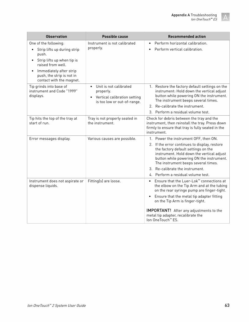
Observation Possible cause Recommended action
One of the following:
• Strip lifts up during strippush.
• Strip lifts up when tip israised from well.
• Immediately after strippush, the strip is not incontact with the magnet.
Instrument is not calibratedproperly.
• Perform horizontal calibration.
• Perform vertical calibration.
Tip grinds into base ofinstrument and Code "1999"displays.
• Unit is not calibratedproperly.
• Vertical calibration settingis too low or out-of-range.
1. Restore the factory default settings on theinstrument: Hold down the vertical adjustbutton while powering ON the instrument.The instrument beeps several times.
2. Re-calibrate the instrument.3. Perform a residual volume test.
Tip hits the top of the tray atstart of run.
Tray is not properly seated inthe instrument.
Check for debris between the tray and theinstrument, then reinstall the tray. Press downfirmly to ensure that tray is fully seated in theinstrument.
Error messages display. Various causes are possible. 1. Power the instrument OFF, then ON.2. If the error continues to display, restore
the factory default settings on theinstrument. Hold down the vertical adjustbutton while powering ON the instrument.The instrument beeps several times.
3. Re-calibrate the instrument.4. Perform a residual volume test.
Instrument does not aspirate ordispense liquids.
Fitting(s) are loose. • Ensure that the Luer-Lok™ connections atthe elbow on the Tip Arm and at the tubingon the rear syringe pump are finger-tight.
• Ensure that the metal tip adapter fittingon the Tip Arm is finger-tight.
IMPORTANT! After any adjustments to themetal tip adapter, recalibrate theIon OneTouch™ ES.
Appendix A TroubleshootingIon OneTouch™ ES A
Ion OneTouch™ 2 System User Guide 63
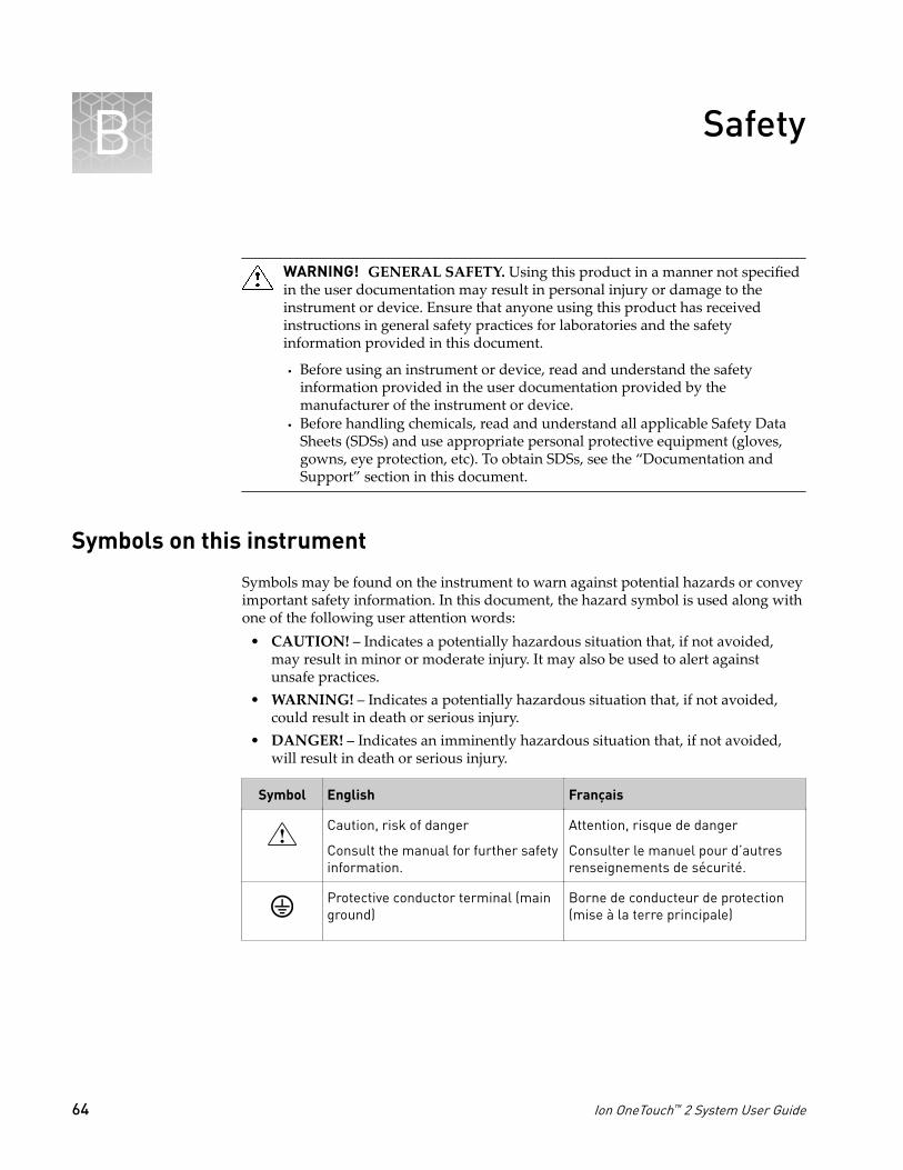
Safety
WARNING! GENERAL SAFETY. Using this product in a manner not specifiedin the user documentation may result in personal injury or damage to theinstrument or device. Ensure that anyone using this product has receivedinstructions in general safety practices for laboratories and the safetyinformation provided in this document.
· Before using an instrument or device, read and understand the safetyinformation provided in the user documentation provided by themanufacturer of the instrument or device.
· Before handling chemicals, read and understand all applicable Safety DataSheets (SDSs) and use appropriate personal protective equipment (gloves,gowns, eye protection, etc). To obtain SDSs, see the “Documentation andSupport” section in this document.
Symbols on this instrument
Symbols may be found on the instrument to warn against potential hazards or conveyimportant safety information. In this document, the hazard symbol is used along withone of the following user attention words:
• CAUTION! – Indicates a potentially hazardous situation that, if not avoided,may result in minor or moderate injury. It may also be used to alert againstunsafe practices.
• WARNING! – Indicates a potentially hazardous situation that, if not avoided,could result in death or serious injury.
• DANGER! – Indicates an imminently hazardous situation that, if not avoided,will result in death or serious injury.
Symbol English Français
Caution, risk of danger
Consult the manual for further safetyinformation.
Attention, risque de danger
Consulter le manuel pour d’autresrenseignements de sécurité.
Protective conductor terminal (mainground)
Borne de conducteur de protection(mise à la terre principale)
B
64 Ion OneTouch™ 2 System User Guide
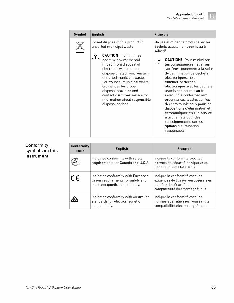
Symbol English Français
Do not dispose of this product inunsorted municipal waste
CAUTION! To minimizenegative environmentalimpact from disposal ofelectronic waste, do notdispose of electronic waste inunsorted municipal waste.Follow local municipal wasteordinances for properdisposal provision andcontact customer service forinformation about responsibledisposal options.
Ne pas éliminer ce produit avec lesdéchets usuels non soumis au trisélectif.
CAUTION! Pour minimiserles conséquences négativessur l’environnement à la suitede l’élimination de déchetsélectroniques, ne paséliminer ce déchetélectronique avec les déchetsusuels non soumis au trisélectif. Se conformer auxordonnances locales sur lesdéchets municipaux pour lesdispositions d’élimination etcommuniquer avec le serviceà la clientèle pour desrenseignements sur lesoptions d’éliminationresponsable.
Conformitymark English Français
Indicates conformity with safetyrequirements for Canada and U.S.A.
Indique la conformité avec lesnormes de sécurité en vigueur auCanada et aux États-Unis.
Indicates conformity with EuropeanUnion requirements for safety andelectromagnetic compatibility.
Indique la conformité avec lesexigences de l’Union européenne enmatière de sécurité et decompatibilité électromagnétique.
Indicates conformity with Australianstandards for electromagneticcompatibility.
Indique la conformité avec lesnormes australiennes régissant lacompatibilité électromagnétique.
Conformitysymbols on thisinstrument
Appendix B SafetySymbols on this instrument B
Ion OneTouch™ 2 System User Guide 65
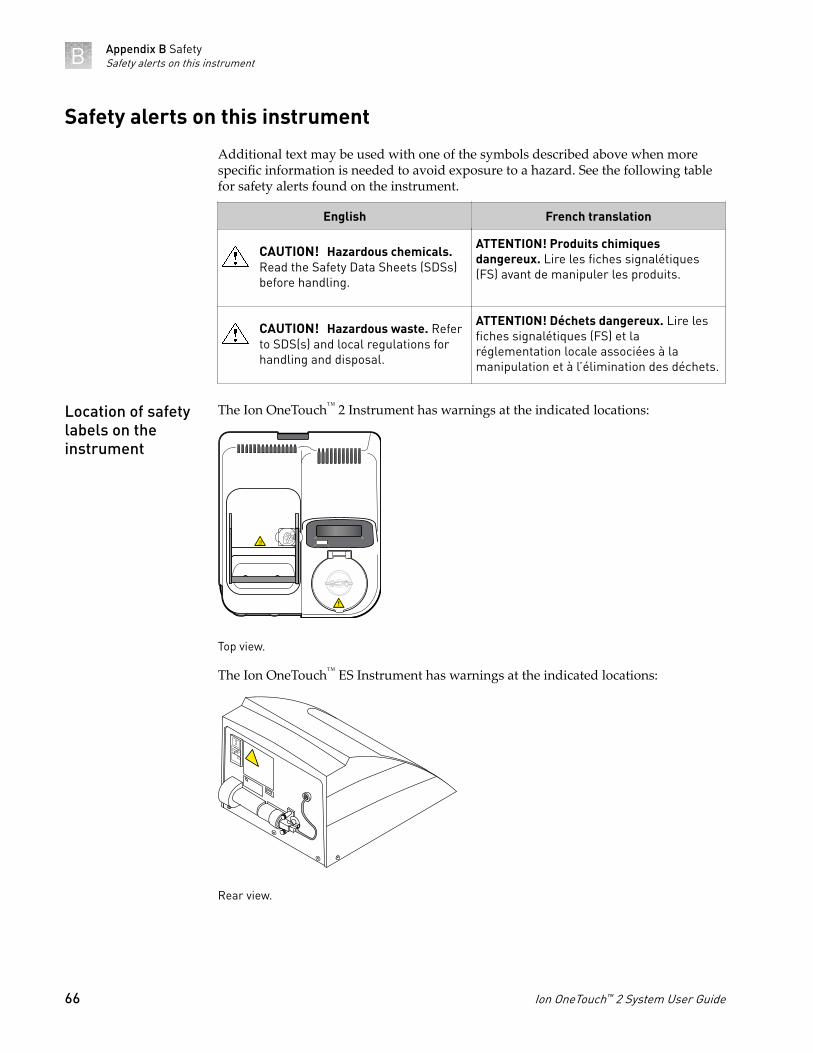
Safety alerts on this instrument
Additional text may be used with one of the symbols described above when morespecific information is needed to avoid exposure to a hazard. See the following tablefor safety alerts found on the instrument.
English French translation
CAUTION! Hazardous chemicals.Read the Safety Data Sheets (SDSs)before handling.
ATTENTION! Produits chimiquesdangereux. Lire les fiches signalétiques(FS) avant de manipuler les produits.
CAUTION! Hazardous waste. Referto SDS(s) and local regulations forhandling and disposal.
ATTENTION! Déchets dangereux. Lire lesfiches signalétiques (FS) et laréglementation locale associées à lamanipulation et à l’élimination des déchets.
The Ion OneTouch™ 2 Instrument has warnings at the indicated locations:
Top view.
The Ion OneTouch™ ES Instrument has warnings at the indicated locations:
Rear view.
Location of safetylabels on theinstrument
Appendix B SafetySafety alerts on this instrumentB
66 Ion OneTouch™ 2 System User Guide
Safety information for instruments not manufactured by ThermoFisher Scientific
Some of the accessories provided as part of the instrument system are not designed orbuilt by Thermo Fisher Scientific. Consult the manufacturer's documentation for theinformation needed for the safe use of these products.
Instrument safety
CAUTION! Do not remove instrument protective covers. If you remove theprotective instrument panels or disable interlock devices, you may be exposedto serious hazards including, but not limited to, severe electrical shock, laserexposure, crushing, or chemical exposure.
WARNING! Ensure appropriate electrical supply. For safe operation of theinstrument:
· Plug the system into a properly grounded receptacle with adequate currentcapacity.
· Ensure the electrical supply is of suitable voltage.· Never operate the instrument with the ground disconnected. Grounding
continuity is required for safe operation of the instrument.
WARNING! Power Supply Line Cords. Use properly configured and approvedline cords for the power supply in your facility.
WARNING! Disconnecting Power. To fully disconnect power either detach orunplug the power cord, positioning the instrument such that the power cord isaccessible.
CAUTION! Cleaning and Decontamination. Use only the cleaning anddecontamination methods specified in the manufacturer's user documentation.It is the responsibility of the operator (or other responsible person) to ensurethe following requirements are met:
· No decontamination or cleaning agents are used that could cause aHAZARD as a result of a reaction with parts of the equipment or withmaterial contained in the equipment.
· The instrument is properly decontaminated a) if hazardous material isspilled onto or into the equipment, and/or b) prior to having the instrumentserviced at your facility or sending the instrument for repair, maintenance,trade-in, disposal, or termination of a loan (decontamination forms may berequested from customer service).
· Before using any cleaning or decontamination methods (except thoserecommended by the manufacturer), users should confirm with themanufacturer that the proposed method will not damage the equipment.
General
Electrical
Cleaning anddecontamination
Appendix B SafetySafety information for instruments not manufactured by Thermo Fisher Scientif-
icB
Ion OneTouch™ 2 System User Guide 67

Safety and electromagnetic compatibility (EMC) standards
The instrument design and manufacture of the Ion OneTouch™ 2 Instrument andIon OneTouch™ ES Instrument complies with the standards and requirements forsafety and electromagnetic compatibility as noted in the following tables:
Reference Description
Ion OneTouch™ 2 Instrument
EU Directive2006/95/EC
European Union “Low Voltage Directive”
IEC 61010-1
EN 61010-1
UL 61010-1
CSA C22.2 No.61010-1
Safety requirements for electrical equipment for measurement,control, and laboratory use – Part 1: General requirements
IEC 61010-2-010
EN 61010-2-010
Safety requirements for electrical equipment for measurement,control and laboratory use – Part 2-010: Particular requirementsfor laboratory equipment for the heating of materials
IEC/EN 61010-2-020 Safety requirements for electrical equipment for measurement,control and laboratory use – Part 2-020: Particular requirementsfor laboratory centrifuges
Ion OneTouch™ ES Instrument
EU Directive2006/95/EC
European Union “Low Voltage Directive”
IEC 61010-1
EN 61010-1
UL 61010-1
CSA C22.2 No.61010-1
Safety requirements for electrical equipment for measurement,control, and laboratory use – Part 1: General requirements
Reference Description
Directive 2012/19/EU European Union “WEEE Directive” – Waste electrical andelectronic equipment
Directive 2011/65/EU European Union “RoHS Directive” – Restriction of hazardoussubstances in electrical and electronic equipment
Safety
Environmentaldesign
Appendix B SafetySafety and electromagnetic compatibility (EMC) standardsB
68 Ion OneTouch™ 2 System User Guide
Reference Description
Directive 2004/108/EC European Union “EMC Directive”
EN 61326-1 Electrical Equipment for Measurement,Control and Laboratory Use – EMCRequirements – Part 1: GeneralRequirements
AS/NZS CISPR 22 2009+A1 2010 Limits and Methods of Measurement ofElectromagnetic DisturbanceCharacteristics of Industrial, Scientific, andMedical (ISM) Radiofrequency Equipment
ICES-003, Issue 5 Industrial, Scientific and Medical (ISM)Radio Frequency Generators
FCC Part 15 Subpart B (47 CFR) U.S. Standard Radio Frequency Devices
Chemical safety
WARNING! GENERAL CHEMICAL HANDLING. To minimize hazards,ensure laboratory personnel read and practice the general safety guidelines forchemical usage, storage, and waste provided below, and consult the relevantSDS for specific precautions and instructions:· Read and understand the Safety Data Sheets (SDSs) provided by the
chemical manufacturer before you store, handle, or work with any chemicalsor hazardous materials. To obtain SDSs, see the “Documentation andSupport” section in this document.
· Minimize contact with chemicals. Wear appropriate personal protectiveequipment when handling chemicals (for example, safety glasses, gloves, orprotective clothing).
· Minimize the inhalation of chemicals. Do not leave chemical containers open.Use only with adequate ventilation (for example, fume hood).
· Check regularly for chemical leaks or spills. If a leak or spill occurs, followthe manufacturer's cleanup procedures as recommended in the SDS.
· Handle chemical wastes in a fume hood.· Ensure use of primary and secondary waste containers. (A primary waste
container holds the immediate waste. A secondary container contains spillsor leaks from the primary container. Both containers must be compatiblewith the waste material and meet federal, state, and local requirements forcontainer storage.)
· After emptying a waste container, seal it with the cap provided.· Characterize (by analysis if necessary) the waste generated by the particular
applications, reagents, and substrates used in your laboratory.· Ensure that the waste is stored, transferred, transported, and disposed of
according to all local, state/provincial, and/or national regulations.· IMPORTANT! Radioactive or biohazardous materials may require special
handling, and disposal limitations may apply.
EMC
Appendix B SafetyChemical safety B
Ion OneTouch™ 2 System User Guide 69

Documentation and support
Customer and technical support
Visit thermofisher.com/support for the latest in services and support, including:• Worldwide contact telephone numbers• Product support, including:
– Product FAQs– Software, patches, and updates
• Order and web support• Product documentation, including:
– User guides, manuals, and protocols– Certificates of Analysis– Safety Data Sheets (SDSs; also known as MSDSs)
Note: For SDSs for reagents and chemicals from other manufacturers,contact the manufacturer.
Limited product warranty
Life Technologies Corporation and/or its affiliate(s) warrant their products as set forthin the Life Technologies' General Terms and Conditions of Sale found on LifeTechnologies' website at www.thermofisher.com/us/en/home/global/terms-and-conditions.html. If you have any questions, please contact LifeTechnologies at www.thermofisher.com/support.
70 Ion OneTouch™ 2 System User Guide

For support visit thermofisher.com/support or email [email protected]
thermofisher.com
16 December 2015