Ion exchange of zeolite membranes by a vacuum ‘flow...
8
Ion exchange of zeolite membranes by a vacuum ‘flow-through’ technique Seok-Jhin Kim a , Christopher W. Jones a , Sankar Nair a,⇑ , Yujun Liu b , Jason S. Moore b , Ravindra S. Dixit b , John G. Pendergast Jr. b , Sagar Sarsani b a School of Chemical & Biomolecular Engineering, Georgia Institute of Technology, 311 Ferst Drive, Atlanta, GA 30332-0100, USA b Engineering & Process Sciences, The Dow Chemical Company, 2301 N. Brazosport Blvd, Freeport, TX 77541, USA article info Article history: Received 13 January 2014 Received in revised form 1 May 2014 Accepted 9 October 2014 Available online 18 October 2014 Keywords: Ion exchange Zeolite membrane Flow-through technique Separation Catalysis abstract Ion exchange of nanoporous (e.g., zeolite) membranes is of increasing importance in their applications as separation devices and catalytic reactors. Ion exchange processes in zeolite membranes are significantly limited by slow hydrated-ion transport rates and the low liquid–solid interfacial area available in com- parison to ion exchange of zeolites in powdered form, thereby leading to long membrane processing and regeneration times. Here, we consider ion exchange processes in zeolite membranes in more detail, and show the much higher efficacy of a vacuum-assisted liquid–vapor ‘flow-through’ method in compar- ison to both the conventional ‘immersion/counter-diffusion’ method as well as a liquid–liquid flow- through method. Na-MFI zeolite disk membranes, made by both in situ and seeded growth, were ion- exchanged with Ga 3+ , Zn 2+ , and Pt 2+ ions in the temperature range of 23–70 °C and exchange times of 5–24 h. The penetration of these ions into the zeolite membranes was investigated in detail by energy- dispersive X-ray (EDX) spectroscopy. Surprisingly, the quantity of exchanged ions in the membranes via the vacuum-assisted ‘flow-through’ technique is found to exceed that achieved by the other two methods by up to a factor of ten, with the liquid–liquid technique being the least efficient. Higher tem- peratures and longer ion exchange times increased the ion exchange efficiency in the vacuum-assisted method. Chemical analysis of the condensed permeate solution by inductively-coupled plasma (ICP) mass spectrometry revealed that both the original Na + and replacement metal cations moved through the membrane in a co-current manner, unlike the conventional counter-current movement of ions in the immersion process. The Na + ions in the membrane experience pressure-driven transport (along with water molecules) to the permeate side, and leave the membrane surface as hydrated vapor-phase cations, thereby allowing the maintenance of a high driving force for ion exchange. In contrast, the conventional counter-current flow technique leads to a decreasing concentration driving force with time. The liquid– liquid method, even though having the same ion concentration and applied pressure driving force as the liquid–vapor method, is very slow because of the large osmotic gradient opposing the permeation of ions and water from the feed to the permeate side. The liquid–vapor ion exchanged MFI membranes showed excellent integrity (as determined by H 2 and CO 2 permeation measurements). Ó 2014 Elsevier Inc. All rights reserved. 1. Introduction Nanoporous (e.g.) polycrystalline zeolite membranes supported on macroporous substrates have attracted large research efforts [1–3]. Zeolite membranes with a variety of crystal structures and pore sizes can effectively perform molecular separations by prefer- ential adsorption and diffusion [4–5]. Zeolite membranes are also gaining increasing attention as catalytic membrane reactors combining reaction and separation in a single device [6–9]. There have been significant efforts to modify zeolite membranes in order to control their performance using methods such as ion exchange [10–17], chemical vapor deposition [18,19], coking treatments [20], and catalytic hydrothermal cracking [21–24]. Ion exchange is a particularly important route to modifying the adsorption, dif- fusion, and catalytic properties of zeolite materials and membranes [25], and a number of studies on the ion-exchange of zeolite mem- branes have appeared [26–33]. For example, Aoki et al. [29] studied the ion exchange of ZSM-5 zeolite membranes with H + , Na + ,K + , Cs + , Ca 2+ and Ba 2+ cations. MFI zeolite membranes with Si/Al ratio of 25 http://dx.doi.org/10.1016/j.micromeso.2014.10.017 1387-1811/Ó 2014 Elsevier Inc. All rights reserved. ⇑ Corresponding author. E-mail address: [email protected] (S. Nair). Microporous and Mesoporous Materials 203 (2015) 170–177 Contents lists available at ScienceDirect Microporous and Mesoporous Materials journal homepage: www.elsevier.com/locate/micromeso
Transcript of Ion exchange of zeolite membranes by a vacuum ‘flow...
Microporous and Mesoporous Materials 203 (2015) 170–177
Contents lists available at ScienceDirect
Microporous and Mesoporous Materials
journal homepage: www.elsevier .com/locate /micromeso
Ion exchange of zeolite membranes by a vacuum ‘flow-through’technique
http://dx.doi.org/10.1016/j.micromeso.2014.10.0171387-1811/� 2014 Elsevier Inc. All rights reserved.
⇑ Corresponding author.E-mail address: [email protected] (S. Nair).
Seok-Jhin Kim a, Christopher W. Jones a, Sankar Nair a,⇑, Yujun Liu b, Jason S. Moore b,Ravindra S. Dixit b, John G. Pendergast Jr. b, Sagar Sarsani b
a School of Chemical & Biomolecular Engineering, Georgia Institute of Technology, 311 Ferst Drive, Atlanta, GA 30332-0100, USAb Engineering & Process Sciences, The Dow Chemical Company, 2301 N. Brazosport Blvd, Freeport, TX 77541, USA
a r t i c l e i n f o
Article history:Received 13 January 2014Received in revised form 1 May 2014Accepted 9 October 2014Available online 18 October 2014
Keywords:Ion exchangeZeolite membraneFlow-through techniqueSeparationCatalysis
a b s t r a c t
Ion exchange of nanoporous (e.g., zeolite) membranes is of increasing importance in their applications asseparation devices and catalytic reactors. Ion exchange processes in zeolite membranes are significantlylimited by slow hydrated-ion transport rates and the low liquid–solid interfacial area available in com-parison to ion exchange of zeolites in powdered form, thereby leading to long membrane processingand regeneration times. Here, we consider ion exchange processes in zeolite membranes in more detail,and show the much higher efficacy of a vacuum-assisted liquid–vapor ‘flow-through’ method in compar-ison to both the conventional ‘immersion/counter-diffusion’ method as well as a liquid–liquid flow-through method. Na-MFI zeolite disk membranes, made by both in situ and seeded growth, were ion-exchanged with Ga3+, Zn2+, and Pt2+ ions in the temperature range of 23–70 �C and exchange times of5–24 h. The penetration of these ions into the zeolite membranes was investigated in detail by energy-dispersive X-ray (EDX) spectroscopy. Surprisingly, the quantity of exchanged ions in the membranesvia the vacuum-assisted ‘flow-through’ technique is found to exceed that achieved by the other twomethods by up to a factor of ten, with the liquid–liquid technique being the least efficient. Higher tem-peratures and longer ion exchange times increased the ion exchange efficiency in the vacuum-assistedmethod. Chemical analysis of the condensed permeate solution by inductively-coupled plasma (ICP) massspectrometry revealed that both the original Na+ and replacement metal cations moved through themembrane in a co-current manner, unlike the conventional counter-current movement of ions in theimmersion process. The Na+ ions in the membrane experience pressure-driven transport (along withwater molecules) to the permeate side, and leave the membrane surface as hydrated vapor-phase cations,thereby allowing the maintenance of a high driving force for ion exchange. In contrast, the conventionalcounter-current flow technique leads to a decreasing concentration driving force with time. The liquid–liquid method, even though having the same ion concentration and applied pressure driving force as theliquid–vapor method, is very slow because of the large osmotic gradient opposing the permeation of ionsand water from the feed to the permeate side. The liquid–vapor ion exchanged MFI membranes showedexcellent integrity (as determined by H2 and CO2 permeation measurements).
� 2014 Elsevier Inc. All rights reserved.
1. Introduction
Nanoporous (e.g.) polycrystalline zeolite membranes supportedon macroporous substrates have attracted large research efforts[1–3]. Zeolite membranes with a variety of crystal structures andpore sizes can effectively perform molecular separations by prefer-ential adsorption and diffusion [4–5]. Zeolite membranes are alsogaining increasing attention as catalytic membrane reactors
combining reaction and separation in a single device [6–9]. Therehave been significant efforts to modify zeolite membranes in orderto control their performance using methods such as ion exchange[10–17], chemical vapor deposition [18,19], coking treatments[20], and catalytic hydrothermal cracking [21–24]. Ion exchangeis a particularly important route to modifying the adsorption, dif-fusion, and catalytic properties of zeolite materials and membranes[25], and a number of studies on the ion-exchange of zeolite mem-branes have appeared [26–33]. For example, Aoki et al. [29] studiedthe ion exchange of ZSM-5 zeolite membranes with H+, Na+, K+, Cs+,Ca2+ and Ba2+ cations. MFI zeolite membranes with Si/Al ratio of 25
S.-J. Kim et al. / Microporous and Mesoporous Materials 203 (2015) 170–177 171
and 600 were stirred in the exchange solution at 95 �C for 2 h. ForSi/Al ratio of 25, permeation properties of the Na-ZSM-5 mem-brane changed with ion exchange while, for Si/Al ratio of 600, nocorrelation between permeance and ion size was observed. Tarditiet al. [25] ion-exchanged the ZSM-5 membranes with Cs+, Ba2+, andSr2+ cations by immersing the membranes in the exchange solutionat 80 �C for 24 h. The single-gas permeation of N2 was conductedbefore the ion-exchange, and before and after the xylene perme-ation tests, but no significant changes in N2 permeation wereobserved. Zhang et al. [30] studied the catalytic activity of MFI zeo-lite membranes by subjecting the membrane to H+ ion-exchangetreatment and used the H+ ion exchanged H-MFI zeolite mem-branes for m-xylene (MX) isomerization. Takata et al. [31] reportedthe effect of repeated ion-exchange from Na+ to H+ on the perme-ances for He, N2 and SF6 at 100 �C for silicalite membrane. Since thecation size of Na+ is larger than that of H+, the gas permeances inthe H+ form were consistently larger than for the Na+ form. Kusak-abe et al. [32] ion exchanged the NaY-type membranes with K+ andLi+ ions. The NaY-type membranes exchanged with K+ and Li+ ionsgave higher and lower CO2/N2 selectivities than the fresh NaY-typemembrane. Hasegawa et al. [33] ion exchanged NaY-type zeolitemembranes with K+, Rb+ or Cs+ ions. Permeation properties of theion-exchanged zeolite membranes were investigated at 35 �C witha CO2/N2 equimolar mixture, and the CO2/N2 selectivity was in theorder: Rb+ = K+ > Cs+ > Na+.
None of the above studies addressed directly the rate and extentof ion exchange of membranes. As discussed by Murad et al. [34],the rate of ion exchange depends upon the driving force for theion exchange as well as the energetic barriers for the ions toenter/leave the membrane through the zeolitic pores. However,with the conventional ion-exchange method (which involvesimmersion of the zeolite membrane into an ion exchange solution),only a limited fraction of ions are exchanged. This is due to theslow concentration-driven transport of hydrated metal cations(which have an effective kinetic diameter of 4–8 Å [35]) in the zeo-lite pores and the lower liquid–solid interface area of a zeolitemembrane in comparison to a powdered zeolite. For example, a1-lm thick zeolite membrane has considerably lower interfacialarea than an equal mass of 1 lm zeolite crystals, since the inter-crystalline boundaries in a good-quality membrane are not easilyaccessible to permeating species. In addition, the location and spa-tial gradient of the exchanged ions in such membranes have notbeen systematically studied.
The main motivation of this work is to investigate methods toincrease the efficiency of ion exchange of zeolitic membranes. Tothis end, a vacuum-assisted liquid–vapor ‘flow-through’ techniqueis described in this work, using MFI zeolite membranes as anexample system. The influence of ion-exchange parameters, suchas different cations, temperature, and ion-exchange time on theMFI zeolite membranes with various Si/Al ratios are describedusing several characterization techniques. The magnitude of ion-exchange is found to be considerably larger than that achievedby conventional immersion methods. As discussed in more detailbelow, the liquid–vapor technique is shown to rely upon the pres-sure-driven co-current transport of hydrated metal ions throughthe membrane, in contrast with other ion-exchange techniquessuch as the conventional ‘immersion’ method and a liquid–liquidflow-through method. In addition, the stability of the ion-exchanged membranes at high operation temperature wasevaluated. The liquid–vapor technique is potentially useful forapplications such as catalysis and separations, since it can providehigh loadings of ions such as Pt2+, Ga3+, and Zn2+. Metal-exchangedzeolites have been widely studied for catalytic processes such aspropane aromatization, dehydrogenation of paraffins, and hydro-amination [36–38]. For example, the introduction of Ga, Zn, andPt species as exchanged cations into ZSM-5 catalysts was found
to increase the rate and selectivity of light-alkane conversionsand to inhibit cracking side-reactions [39]. Ion-exchanged zeolitemembranes have potential as catalytic membrane reactors tointensify such processes [40].
2. Experimental methods
2.1. Membrane synthesis by in situ crystallization
The aluminosilicate MFI zeolite membrane was synthesized ona porous a-alumina disk by the in situ crystallization method. Mac-roporous a-alumina disks (Coorstek) of 1 in. diameter, 1 mm thick-ness, and 25% porosity were used as supports for MFI zeolitemembrane preparation. One side of the disk was polished by no.600 SiC sandpaper for growing zeolite membrane. The synthesissolution was prepared as follows: tetrapropylammonium hydrox-ide (TPAOH, 1 M, Sigma–Aldrich) and NaAlO2 (Sigma–Aldrich)were mixed in deionized water. After 30 min of stirring, tetraethylorthosilicate (TEOS, 98%, Acros) was added dropwise to the solu-tion under constant stirring. The molar composition of the gelwas TEOS: 0.095 TPAOH: 35.42 H2O: X NaAlO2. The X value wasvaried from 0 to 0.040, corresponding to a range of Si/Al ratios from1 to 15. After the precursor was stirred for 3 h, it was transferredinto the Teflon-lined stainless steel autoclave (Parr). The polisheda-alumina disk was placed vertically at the bottom of the vesseland completely immersed in the synthesis solution. The synthesisexperiments were performed at 150 �C for 17 h. After the hydro-thermal reaction, the membrane was washed thoroughly withdeionized water, dried, and calcined in air at 550 �C for 6 h toremove the template. The membranes were dried at 70 �C in anoven for overnight before ion exchange.
2.2. Membrane synthesis by seeded growth
To prepare a pure-silica MFI seed suspension, the synthesissolution was prepared by dissolving the fumed silica and NaOHpellets in 1 M TPAOH solution at 80 �C. It had a molar ratio of0.33 SiO2: 0.1 TPAOH: 0.035 NaOH: 5.56 H2O [41]. The precursorwas aged at room temperature for 4 h before receiving hydrother-mal treatment. The hydrothermal synthesis was performed at120 �C for 4 h. After hydrothermal synthesis, the resultant silicalitenanoparticle slurry was washed in deionized water in a centrifuge.The seeds were then dip-coated on the alumina supports followingthe procedure described elsewhere [42]. After dip-coating, the diskwas dried at 60 �C for 24 h in an oven. The seed layer coated diskwas then calcined in air at 550 �C for 6 h to remove the templatefrom the seed crystals and consolidate the seed layer. The precur-sor solution for secondary growth was the same as that used forin situ crystallization. The seeded a-alumina disk was placed andimmersed in the synthesis solution. The secondary growth synthe-sis experiments were performed at 150 �C for 17 h.
2.3. Ion exchange methods
For the conventional ion exchange process, the zeolitemembranes were immersed in the ion-exchange solution[16,25,30,31]. In some cases, the membrane was tied to a magneticstirrer and placed at the bottom of a flask and stirred in the ion-exchange solution [11,17]. In this work, the zeolite membrane diskwas attached to a magnetic stirrer bar with an epoxy adhesive,immersed in the ion exchange solution, and continuously stirred.For the vacuum-assisted liquid–vapor ‘flow-through’ process, thezeolite membranes were immersed with the membrane surfacefacing the ion exchange solution, and ion-exchanged by thepressure and concentration-induced total chemical potential

172 S.-J. Kim et al. / Microporous and Mesoporous Materials 203 (2015) 170–177
difference created between the two sides of the membrane. Thedisk-supported zeolite membrane was attached to a bell-shapedglass tube with an epoxy adhesive, and with the membrane surfacefacing out of the bell-shaped tube (Fig. 1). The membrane surfacewas then immersed into the ion exchange solution bath. The otherside of the tube was connected to a vacuum pump, to create aliquid–vapor pressure differential of approximately 1 atm acrossthe membrane. Before ion exchange, the vacuum-tightness of thetube-membrane assembly and all connections was verified. Thepressure differential between the two sides of the membranewas monitored by a pressure gauge. For the liquid–liquid ‘flow-through’ process, the disk-supported zeolite membrane wasattached to a bell-shaped glass tube with an epoxy adhesive, andwith the membrane surface facing into the bell-shaped tube. Thetube was connected to a water pump which introduces a pressur-ized ion exchange solution to the membrane surface with a liquid–liquid pressure differential of 1 atm across the membrane. The tubeassembly was immersed into a bath containing deionized water atatmospheric pressure, which contacts the permeate side of themembrane.
Ion-exchange solutions with 1 mM concentration containingGa3+, Zn2+, or Pt2+ ions were prepared from Ga(NO3)3�H2O,Zn(NO3)2�H2O, and Pt(NH3)4Cl2�H2O, respectively. The ion-exchange solution was heated to 23–70 �C under constant stirring.All three ion-exchange methods were carried out in the tempera-ture range of 23–70 �C for time periods of 5–24 h. After ionexchange, the membrane was washed in deionized water at23 �C for 3 min, immersed in DI water for 15 min, and washedagain for 3 min. The membrane was then dried in an oven at70 �C overnight, and calcined at 550 �C for 6 h.
2.4. Characterization
Scanning Electron Microscopy (SEM) images and energy disper-sive X-ray spectroscopy (EDX) analyses were obtained on a JEOLLEO-1530 at a landing energy of 15 kV using the ‘InLens’ modedetector. The membrane samples were coated with gold to preventsurface charging effects. X-ray diffraction (XRD) patterns of themembranes were obtained using a PANalytical X’pert diffractome-ter using a Cu-K-alpha X-ray source, diffracted beam collimator,and a proportional detector. Elemental analysis by inductively-coupled plasma (ICP) was carried out by Columbia Analytics (Tuc-son, AZ). All membranes were dried at 70 �C for 12 h in an ovenbefore gas permeation measurements. The membranes were
Fig. 1. Schematic diagram of experimental apparatus for MFI mem
mounted in a stainless steel cell with the zeolite surface facingthe feed side, placed in a temperature-programmable oven, andfurther degassed under vacuum for 2 h at 23 �C. Before calcination,the integrity of the zeolite membrane was checked via He perme-ation measurements, for which a transient permeation setup withupstream pressure of 25–30 psi at room temperature wasemployed. The membranes had very low He permeances (less than1.0 � 10�10 mol m�2 s�1 Pa�1). For calcined membranes, H2 andCO2 permeation measurements were carried out at 23, 75, 125,and 175 �C. The feed side was maintained at 30 psi, and the perme-ate side was evacuated to 0.1 psi. The gas permeance was mea-sured by isolating the vacuum and recording the rate of pressurerise in a collection vessel of known volume on the permeate side.
3. Results and discussion
Fig. S1a (Supporting information) shows SEM images of a typi-cal pure-silica MFI seed layer obtained by dip-coating. MFI nano-crystals with an average particle size of �100 nm were obtainedby conventional heating at 120 �C for 4 h. Fig. S1b and S1c showSEM images of the Na-MFI (or Na-ZSM-5) zeolite membrane afterin situ crystallization in precursors with Si/Al = 25 and the MFImembrane after secondary growth in precursors with Si/Al = 25.The thicknesses of the zeolite membranes are 4–6 lm as estimatedfrom the cross-section SEM images. The XRD patterns of the zeolitemembranes are shown in Fig. S2 (Supporting information). The MFIzeolite membranes made by in situ crystallization showed (h00)/(0k0) out-of-plane orientation, and the MFI zeolite membranesfrom secondary growth method showed (h0l) orientation.
Fig. 2 shows the SEM micrographs of the surface and cross-section of the secondary grown zeolite membrane before and aftervacuum-assisted ion-exchange. The secondary-grown zeolitemembranes showed intergrown polycrystalline films and thethickness of the zeolite layer was 5–6 lm. The cross-section/sur-face microstructure of the ion-exchanged membrane wasunchanged from that of the fresh membranes. In addition, the vac-uum-assisted ion-exchanged zeolite membranes were kept in airat 550 �C for 0 h, 24 h, and 48 h, respectively, to check the high-temperature stability. The SEM images in Fig. S3 (Supporting infor-mation) were taken after aging at 550 �C. No significant change inmembrane morphology was observed after high-temperatureexposure. This suggests that the ion-exchanged zeolite MFImembranes are thermally stable, which make them useful forhigh-temperature applications. As shown in Fig. S4 (Supporting
brane ion-exchange by a vacuum ‘flow-through’ technique.

Fig. 2. SEM images of the zeolite MFI membranes by secondary growth inprecursors with Si/Al = 25: (a1 and a2) before ion-exchange, (b1 and b2) afterGa3+ ion-exchange at 23 �C for 5 h, (c1 and c2) after Zn2+ ion-exchange at 23 �C for5 h, and (d1 and d2) after Pt2+ ion-exchange at 23 �C for 5 h.
S.-J. Kim et al. / Microporous and Mesoporous Materials 203 (2015) 170–177 173
information), the XRD patterns of the ion-exchanged membranesbefore and after thermal aging were essentially identical.
The Si, Al, Na, Ga, Zn, and Pt compositions were measured usingenergy-dispersive X-ray (EDX) spectroscopy. The (oxygen-free)composition analysis taken from the top surfaces of the ion-exchanged membranes is shown in Table 1. Based upon the inci-dent energy of the electron beam, the membrane depth over whichthe composition analysis is carried out is estimated as 1–2 lm. MFIzeolite membranes were obtained by secondary growth in precur-sors with Si/Al = 25, and ion-exchanged by the vacuum-assisted‘flow-through’ technique with Ga3+, Zn2+, or Pt2+ ions. The EDX ele-mental analysis shows that the Ga/Al, Zn/Al, and Pt/Al ratiosincreased substantially after ion exchange indicating increase ofexchanged ion density in the zeolite membrane. For the Ga- andZn-exchanged membranes, the increase in Ga/Al, Zn/Al, and Pt/Alratios showed good agreement with the corresponding decrease
Table 1Elemental surface composition of Na-MFI membranes secondary-grown from precursor sexchange with Ga3+, Zn2+, and Pt2+ ions at 70 �C for 24 h, 70 �C for 24 h, and 23 �C for 5 h
Si/Ala EDX atomic %
Si Al Na Ga Z
Ga 25 Before 94.2 3.27 2.57 – –After 94.9 3.74 0.24 1.07 –
Zn 25 Before 94.1 3.27 2.67 – –After 94.5 3.48 0.84 – 1
Pt 25 Before 93.6 3.93 2.43 – –After 94.5 3.81 0.93 – –
a Si/Al ratio in precursor solution.b Si/Al ratio in the resulting zeolite membrane.
in Na/Al ratio. For example, in the case of exchange of monovalentNa+ ions with trivalent Ga3+ cations, the decrease in Na/Al ratio of0.73 (i.e., from 0.79 to 0.06) is commensurate with the increase ofGa/Al ratio from 0 to 0.29. The Al atomic % and the Si/Al ratio didnot change significantly after ion exchange, indicating that poten-tial dealumination of the zeolite membrane was not a significantfactor in comparison with the degree of ion exchange.
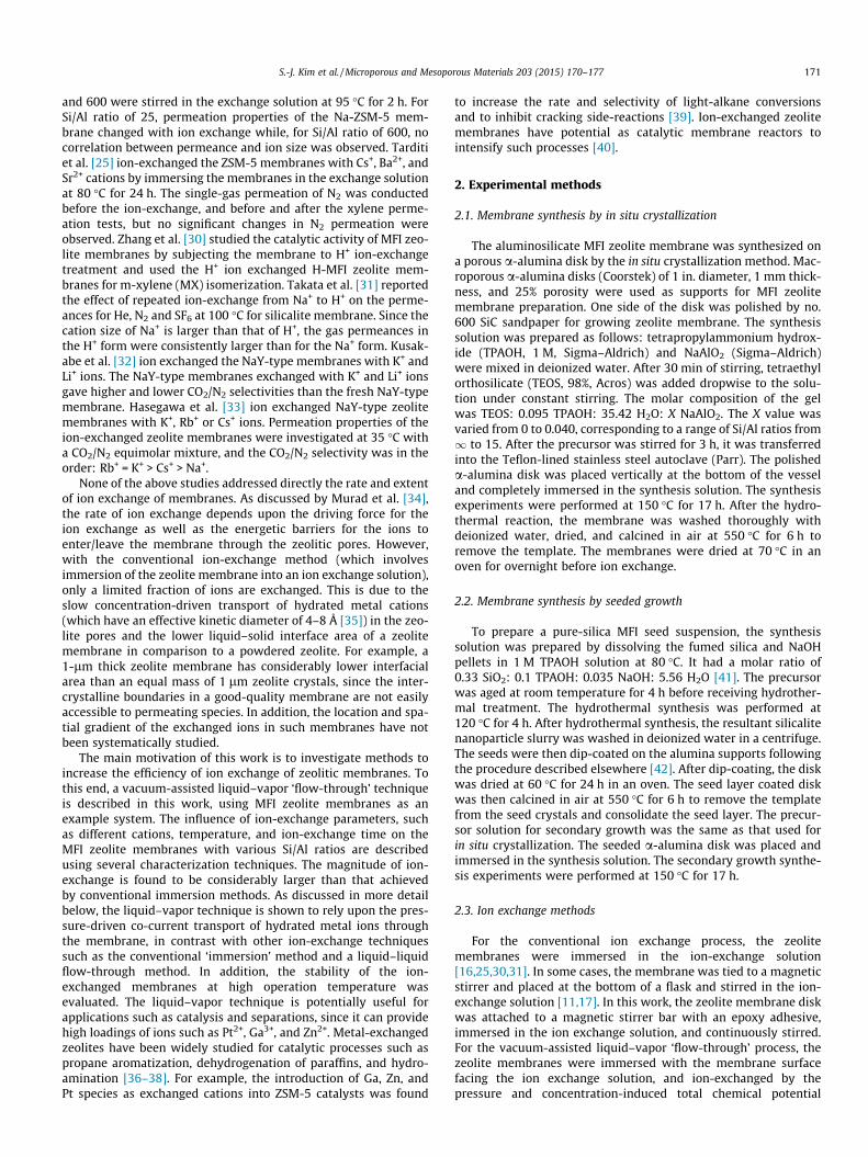
Fig. 3 shows the surface EDX analysis of Ga3+ ion-exchangedsecondary grown membranes as a function of ion exchange time.The Ga/Na ratio of the membrane ion-exchanged at 70 �C wasmuch higher than that of the membrane exchanged at 23 �C, andthe differences became more significant as the ion exchange timeincreased. For the membrane exchanged by the vacuum-assisted‘flow-through’ technique, Ga/Na was about five times higher thanthat of the membrane exchanged by the conventional immersionmethod. This clearly indicated a much larger driving force acrossthe membrane in the vacuum-assisted process. Table 2 shows adirect comparison of the three ion exchange methods using sec-ondary-grown membranes at 70 �C and a duration of 24 h. It isclearly seen that the vacuum-assisted liquid–vapor method pro-vides 5–10 times more efficient ion exchange than the other twomethods. Furthermore, the liquid–liquid method produces a muchsmaller level of ion exchange than the other two methods. The dif-ferences between these three methods, which are not immediatelyobvious, can be understood in terms of the type and direction ofthe driving forces for ion transport. In the vacuum-assistedliquid–vapor method, the pressure and concentration drivingforces for permeation of water, Ga3+, and Na+ all exist in the samedirection, i.e., from the feed side to the permeate side. Thisco-current flow of water and ions can be maintained throughoutthe ion exchange process. In the conventional immersion process,there is no pressure driving force for permeation. The concentra-tion driving forces for Ga3+ and Na+ transport oppose each other.Finally, the liquid–liquid process is limited by the large osmoticdifferential (about 2.2, 2.4, and 1.7 atm for Ga3+, Zn2+, and Pt2+,respectively) that opposes the applied pressure differential(1 atm) and the ion concentration gradient. The large back-permeation of water prevents effective ion exchange, and a muchlarger feed pressure will be required for effective ion exchange.
Fig. 4 shows a comparison of the Ga/Al, Zn/Al, and Pt/Al ratiosresulting from ion-exchange of in situ and secondary-grown Na-MFI membranes with two different Si/Al ratios (15 and 25). Asexpected these ratios increased with decreasing Si/Al ratios,because the membrane with lower Si/Al ratio has more ion-exchange sites. The membranes made by in situ crystallization con-sistently showed higher ion exchange than the secondary-grownmembranes under the same ion exchange conditions (23 �C and5 h). This is clearly due to the slower rate of transport of cationsin the secondary-grown membranes (which are (h0l)-oriented)in comparison to the in situ membranes (which are (h00)/(0k0)oriented and have the straight and sinusoidal pore channels
olutions with Si/Al ratios of 25, before and after vacuum-assisted ‘flow-through’ ion, respectively. The atomic % values are on an oxygen-free basis.
Si/Alb Na/Al Ga/Al Zn/Al Pt/Al
n Pt
– 29 0.79 – – –– 25 0.06 0.29 – –– 29 0.82 – – –
.18 – 27 0.24 – 0.34 –– 24 0.62 – – –0.74 25 0.24 – – 0.19
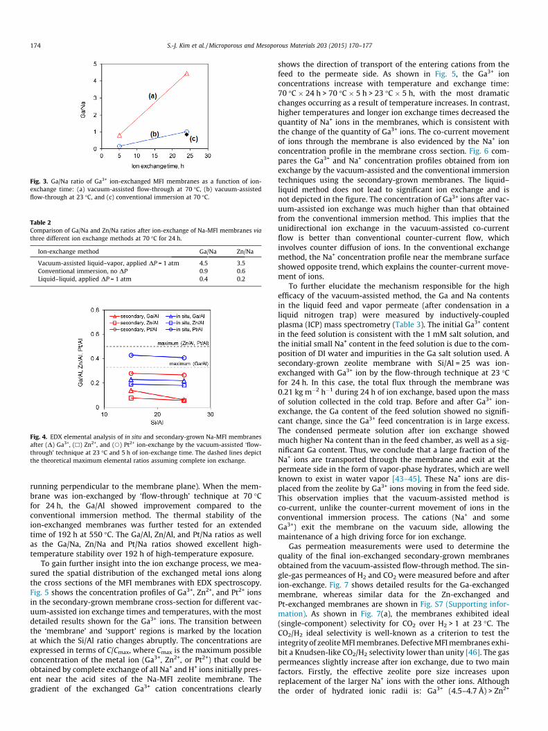
Fig. 3. Ga/Na ratio of Ga3+ ion-exchanged MFI membranes as a function of ion-exchange time: (a) vacuum-assisted flow-through at 70 �C, (b) vacuum-assistedflow-through at 23 �C, and (c) conventional immersion at 70 �C.
Table 2Comparison of Ga/Na and Zn/Na ratios after ion-exchange of Na-MFI membranes viathree different ion exchange methods at 70 �C for 24 h.
Ion-exchange method Ga/Na Zn/Na
Vacuum-assisted liquid–vapor, applied DP = 1 atm 4.5 3.5Conventional immersion, no DP 0.9 0.6Liquid–liquid, applied DP = 1 atm 0.4 0.2
Fig. 4. EDX elemental analysis of in situ and secondary-grown Na-MFI membranesafter (D) Ga3+, (h) Zn2+, and (s) Pt2+ ion-exchange by the vacuum-assisted ‘flow-through’ technique at 23 �C and 5 h of ion-exchange time. The dashed lines depictthe theoretical maximum elemental ratios assuming complete ion exchange.
174 S.-J. Kim et al. / Microporous and Mesoporous Materials 203 (2015) 170–177
running perpendicular to the membrane plane). When the mem-brane was ion-exchanged by ‘flow-through’ technique at 70 �Cfor 24 h, the Ga/Al showed improvement compared to theconventional immersion method. The thermal stability of theion-exchanged membranes was further tested for an extendedtime of 192 h at 550 �C. The Ga/Al, Zn/Al, and Pt/Na ratios as wellas the Ga/Na, Zn/Na and Pt/Na ratios showed excellent high-temperature stability over 192 h of high-temperature exposure.
To gain further insight into the ion exchange process, we mea-sured the spatial distribution of the exchanged metal ions alongthe cross sections of the MFI membranes with EDX spectroscopy.Fig. 5 shows the concentration profiles of Ga3+, Zn2+, and Pt2+ ionsin the secondary-grown membrane cross-section for different vac-uum-assisted ion exchange times and temperatures, with the mostdetailed results shown for the Ga3+ ions. The transition betweenthe ‘membrane’ and ‘support’ regions is marked by the locationat which the Si/Al ratio changes abruptly. The concentrations areexpressed in terms of C/Cmax, where Cmax is the maximum possibleconcentration of the metal ion (Ga3+, Zn2+, or Pt2+) that could beobtained by complete exchange of all Na+ and H+ ions initially pres-ent near the acid sites of the Na-MFI zeolite membrane. Thegradient of the exchanged Ga3+ cation concentrations clearly
shows the direction of transport of the entering cations from thefeed to the permeate side. As shown in Fig. 5, the Ga3+ ionconcentrations increase with temperature and exchange time:70 �C � 24 h > 70 �C � 5 h > 23 �C � 5 h, with the most dramaticchanges occurring as a result of temperature increases. In contrast,higher temperatures and longer ion exchange times decreased thequantity of Na+ ions in the membranes, which is consistent withthe change of the quantity of Ga3+ ions. The co-current movementof ions through the membrane is also evidenced by the Na+ ionconcentration profile in the membrane cross section. Fig. 6 com-pares the Ga3+ and Na+ concentration profiles obtained from ionexchange by the vacuum-assisted and the conventional immersiontechniques using the secondary-grown membranes. The liquid–liquid method does not lead to significant ion exchange and isnot depicted in the figure. The concentration of Ga3+ ions after vac-uum-assisted ion exchange was much higher than that obtainedfrom the conventional immersion method. This implies that theunidirectional ion exchange in the vacuum-assisted co-currentflow is better than conventional counter-current flow, whichinvolves counter diffusion of ions. In the conventional exchangemethod, the Na+ concentration profile near the membrane surfaceshowed opposite trend, which explains the counter-current move-ment of ions.
To further elucidate the mechanism responsible for the highefficacy of the vacuum-assisted method, the Ga and Na contentsin the liquid feed and vapor permeate (after condensation in aliquid nitrogen trap) were measured by inductively-coupledplasma (ICP) mass spectrometry (Table 3). The initial Ga3+ contentin the feed solution is consistent with the 1 mM salt solution, andthe initial small Na+ content in the feed solution is due to the com-position of DI water and impurities in the Ga salt solution used. Asecondary-grown zeolite membrane with Si/Al = 25 was ion-exchanged with Ga3+ ion by the flow-through technique at 23 �Cfor 24 h. In this case, the total flux through the membrane was0.21 kg m�2 h�1 during 24 h of ion exchange, based upon the massof solution collected in the cold trap. Before and after Ga3+ ion-exchange, the Ga content of the feed solution showed no signifi-cant change, since the Ga3+ feed concentration is in large excess.The condensed permeate solution after ion exchange showedmuch higher Na content than in the feed chamber, as well as a sig-nificant Ga content. Thus, we conclude that a large fraction of theNa+ ions are transported through the membrane and exit at thepermeate side in the form of vapor-phase hydrates, which are wellknown to exist in water vapor [43–45]. These Na+ ions are dis-placed from the zeolite by Ga3+ ions moving in from the feed side.This observation implies that the vacuum-assisted method isco-current, unlike the counter-current movement of ions in theconventional immersion process. The cations (Na+ and someGa3+) exit the membrane on the vacuum side, allowing themaintenance of a high driving force for ion exchange.
Gas permeation measurements were used to determine thequality of the final ion-exchanged secondary-grown membranesobtained from the vacuum-assisted flow-through method. The sin-gle-gas permeances of H2 and CO2 were measured before and afterion-exchange. Fig. 7 shows detailed results for the Ga-exchangedmembrane, whereas similar data for the Zn-exchanged andPt-exchanged membranes are shown in Fig. S7 (Supporting infor-mation). As shown in Fig. 7(a), the membranes exhibited ideal(single-component) selectivity for CO2 over H2 > 1 at 23 �C. TheCO2/H2 ideal selectivity is well-known as a criterion to test theintegrity of zeolite MFI membranes. Defective MFI membranes exhi-bit a Knudsen-like CO2/H2 selectivity lower than unity [46]. The gaspermeances slightly increase after ion exchange, due to two mainfactors. Firstly, the effective zeolite pore size increases uponreplacement of the larger Na+ ions with the other ions. Althoughthe order of hydrated ionic radii is: Ga3+ (4.5–4.7 Å) > Zn2+

Fig. 5. Ion concentration profiles measured by EDX spectroscopy along the zeolite membrane cross-section of Na-MFI membranes secondary-grown from precursors with Si/Al = 25, before and after (a1 and a2) Ga3+, (b1 and b2) Zn2+, and (c1 and c2) Pt2+ ion-exchange by the vacuum-assisted liquid–vapor ‘flow through’ method.
Fig. 6. Ga3+ and Na+ ion concentration profiles measured by EDX spectroscopy along the zeolite membrane cross-section of Na-MFI membranes secondary-grown fromprecursors with Si/Al = 25, after ion-exchange for 24 h at 70 �C by the vacuum-assisted liquid–vapor ‘flow through’ method and the conventional immersion method.
Table 3Concentrations of Ga and Na in the feed and (condensed) permeate solution asdetermined by ICP analysis, for a secondary-grown Na-MFI membrane with Si/Al = 25before and after Ga3+ ion-exchange by vacuum-assisted ‘flow-through’ technique at23 �C for 24 h.
Ga (ppm) Na (ppm)
Feed before ion-exchange 52 7Feed after ion-exchange 54 10Permeate after ion-exchange 5 20
S.-J. Kim et al. / Microporous and Mesoporous Materials 203 (2015) 170–177 175
(4.3 Å) > Pt2+ (4.0–4.4 Å) > Na+ (3.6 Å), the dehydrated ionic radiiare in the reverse order: Na+ (1.16 Å) > Pt2+ (0.94 Å) > Zn2+
(0.88 Å) > Ga3+ (0.74 Å). The latter ionic radii are likely more
appropriate in relation to the above permeation measurements,performed on calcined membranes that were further degassedovernight before permeation measurements. Secondly, it is alsoclear that the number of metal cations present in the membranedrastically decreases when the monovalent Na+ cations are replacedby divalent (Pt2+, Zn2+) and trivalent (Ga3+) cations. The CO2/H2
permselectivities did not change significantly after ion exchange,indicating that the membrane integrity was not affected by the vac-uum-assisted ion exchange process. The temperature dependencesof the H2 and CO2 permeances for the Na-MFI and the Ga-exchanged-MFI membranes are also similar. The single-gas H2 andCO2 permeation properties were further tested at 550 �C after agingfor 0 h, 48 h, 96 h, 144 h, 192 h, and 240 h, respectively, as shown in
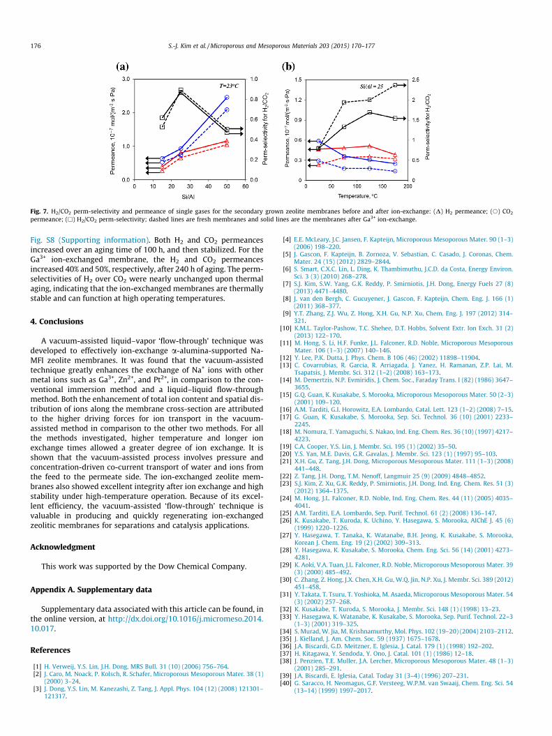
Fig. 7. H2/CO2 perm-selectivity and permeance of single gases for the secondary grown zeolite membranes before and after ion-exchange: (D) H2 permeance; (s) CO2
permeance; (h) H2/CO2 perm-selectivity; dashed lines are fresh membranes and solid lines are the membranes after Ga3+ ion-exchange.
176 S.-J. Kim et al. / Microporous and Mesoporous Materials 203 (2015) 170–177
Fig. S8 (Supporting information). Both H2 and CO2 permeancesincreased over an aging time of 100 h, and then stabilized. For theGa3+ ion-exchanged membrane, the H2 and CO2 permeancesincreased 40% and 50%, respectively, after 240 h of aging. The perm-selectivities of H2 over CO2 were nearly unchanged upon thermalaging, indicating that the ion-exchanged membranes are thermallystable and can function at high operating temperatures.
4. Conclusions
A vacuum-assisted liquid–vapor ‘flow-through’ technique wasdeveloped to effectively ion-exchange a-alumina-supported Na-MFI zeolite membranes. It was found that the vacuum-assistedtechnique greatly enhances the exchange of Na+ ions with othermetal ions such as Ga3+, Zn2+, and Pt2+, in comparison to the con-ventional immersion method and a liquid–liquid flow-throughmethod. Both the enhancement of total ion content and spatial dis-tribution of ions along the membrane cross-section are attributedto the higher driving forces for ion transport in the vacuum-assisted method in comparison to the other two methods. For allthe methods investigated, higher temperature and longer ionexchange times allowed a greater degree of ion exchange. It isshown that the vacuum-assisted process involves pressure andconcentration-driven co-current transport of water and ions fromthe feed to the permeate side. The ion-exchanged zeolite mem-branes also showed excellent integrity after ion exchange and highstability under high-temperature operation. Because of its excel-lent efficiency, the vacuum-assisted ‘flow-through’ technique isvaluable in producing and quickly regenerating ion-exchangedzeolitic membranes for separations and catalysis applications.
Acknowledgment
This work was supported by the Dow Chemical Company.
Appendix A. Supplementary data
Supplementary data associated with this article can be found, inthe online version, at http://dx.doi.org/10.1016/j.micromeso.2014.10.017.
References
[1] H. Verweij, Y.S. Lin, J.H. Dong, MRS Bull. 31 (10) (2006) 756–764.[2] J. Caro, M. Noack, P. Kolsch, R. Schafer, Microporous Mesoporous Mater. 38 (1)
(2000) 3–24.[3] J. Dong, Y.S. Lin, M. Kanezashi, Z. Tang, J. Appl. Phys. 104 (12) (2008) 121301–
121317.
[4] E.E. McLeary, J.C. Jansen, F. Kapteijn, Microporous Mesoporous Mater. 90 (1–3)(2006) 198–220.
[5] J. Gascon, F. Kapteijn, B. Zornoza, V. Sebastian, C. Casado, J. Coronas, Chem.Mater. 24 (15) (2012) 2829–2844.
[6] S. Smart, C.X.C. Lin, L. Ding, K. Thambimuthu, J.C.D. da Costa, Energy Environ.Sci. 3 (3) (2010) 268–278.
[7] S.J. Kim, S.W. Yang, G.K. Reddy, P. Smirniotis, J.H. Dong, Energy Fuels 27 (8)(2013) 4471–4480.
[8] J. van den Bergh, C. Gucuyener, J. Gascon, F. Kapteijn, Chem. Eng. J. 166 (1)(2011) 368–377.
[9] Y.T. Zhang, Z.J. Wu, Z. Hong, X.H. Gu, N.P. Xu, Chem. Eng. J. 197 (2012) 314–321.
[10] K.M.L. Taylor-Pashow, T.C. Shehee, D.T. Hobbs, Solvent Extr. Ion Exch. 31 (2)(2013) 122–170.
[11] M. Hong, S. Li, H.F. Funke, J.L. Falconer, R.D. Noble, Microporous MesoporousMater. 106 (1–3) (2007) 140–146.
[12] Y. Lee, P.K. Dutta, J. Phys. Chem. B 106 (46) (2002) 11898–11904.[13] C. Covarrubias, R. Garcia, R. Arriagada, J. Yanez, H. Ramanan, Z.P. Lai, M.
Tsapatsis, J. Membr. Sci. 312 (1–2) (2008) 163–173.[14] M. Demertzis, N.P. Evmiridis, J. Chem. Soc., Faraday Trans. I (82) (1986) 3647–
3655.[15] G.Q. Guan, K. Kusakabe, S. Morooka, Microporous Mesoporous Mater. 50 (2–3)
(2001) 109–120.[16] A.M. Tarditi, G.I. Horowitz, E.A. Lombardo, Catal. Lett. 123 (1–2) (2008) 7–15.[17] G. Guan, K. Kusakabe, S. Morooka, Sep. Sci. Technol. 36 (10) (2001) 2233–
2245.[18] M. Nomura, T. Yamaguchi, S. Nakao, Ind. Eng. Chem. Res. 36 (10) (1997) 4217–
4223.[19] C.A. Cooper, Y.S. Lin, J. Membr. Sci. 195 (1) (2002) 35–50.[20] Y.S. Yan, M.E. Davis, G.R. Gavalas, J. Membr. Sci. 123 (1) (1997) 95–103.[21] X.H. Gu, Z. Tang, J.H. Dong, Microporous Mesoporous Mater. 111 (1–3) (2008)
441–448.[22] Z. Tang, J.H. Dong, T.M. Nenoff, Langmuir 25 (9) (2009) 4848–4852.[23] S.J. Kim, Z. Xu, G.K. Reddy, P. Smirniotis, J.H. Dong, Ind. Eng. Chem. Res. 51 (3)
(2012) 1364–1375.[24] M. Hong, J.L. Falconer, R.D. Noble, Ind. Eng. Chem. Res. 44 (11) (2005) 4035–
4041.[25] A.M. Tarditi, E.A. Lombardo, Sep. Purif. Technol. 61 (2) (2008) 136–147.[26] K. Kusakabe, T. Kuroda, K. Uchino, Y. Hasegawa, S. Morooka, AIChE J. 45 (6)
(1999) 1220–1226.[27] Y. Hasegawa, T. Tanaka, K. Watanabe, B.H. Jeong, K. Kusakabe, S. Morooka,
Korean J. Chem. Eng. 19 (2) (2002) 309–313.[28] Y. Hasegawa, K. Kusakabe, S. Morooka, Chem. Eng. Sci. 56 (14) (2001) 4273–
4281.[29] K. Aoki, V.A. Tuan, J.L. Falconer, R.D. Noble, Microporous Mesoporous Mater. 39
(3) (2000) 485–492.[30] C. Zhang, Z. Hong, J.X. Chen, X.H. Gu, W.Q. Jin, N.P. Xu, J. Membr. Sci. 389 (2012)
451–458.[31] Y. Takata, T. Tsuru, T. Yoshioka, M. Asaeda, Microporous Mesoporous Mater. 54
(3) (2002) 257–268.[32] K. Kusakabe, T. Kuroda, S. Morooka, J. Membr. Sci. 148 (1) (1998) 13–23.[33] Y. Hasegawa, K. Watanabe, K. Kusakabe, S. Morooka, Sep. Purif. Technol. 22–3
(1–3) (2001) 319–325.[34] S. Murad, W. Jia, M. Krishnamurthy, Mol. Phys. 102 (19–20) (2004) 2103–2112.[35] J. Kielland, J. Am. Chem. Soc. 59 (1937) 1675–1678.[36] J.A. Biscardi, G.D. Meitzner, E. Iglesia, J. Catal. 179 (1) (1998) 192–202.[37] H. Kitagawa, Y. Sendoda, Y. Ono, J. Catal. 101 (1) (1986) 12–18.[38] J. Penzien, T.E. Muller, J.A. Lercher, Microporous Mesoporous Mater. 48 (1–3)
(2001) 285–291.[39] J.A. Biscardi, E. Iglesia, Catal. Today 31 (3–4) (1996) 207–231.[40] G. Saracco, H. Neomagus, G.F. Versteeg, W.P.M. van Swaaij, Chem. Eng. Sci. 54
(13–14) (1999) 1997–2017.

S.-J. Kim et al. / Microporous and Mesoporous Materials 203 (2015) 170–177 177
[41] Vroon, Z.A.E.P., Synthesis and transport properties of thin ceramic supportedzeolite (MFI) membranes (Ph.D. Dissertation) University of Twente, TheNetherlands, 1995.
[42] Z. Tang, S.J. Kim, X.H. Gu, J.H. Dong, Microporous Mesoporous Mater. 118 (1–3)(2009) 224–231.
[43] S.K. Searles, P. Kebarle, Can. J. Chem. 47 (1969) 2619–2627.
[44] A.T. Blades, P. Jayaweera, M.G. Ikonomou, P. Kebarle, J. Chem. Phys. 92 (10)(1990) 5900–5906.
[45] A. Kerridge, N. Kaltsoyannis, Chem. Eur. J. 17 (18) (2011) 5060–5067.[46] H.B. Wang, Y.S. Lin, Microporous Mesoporous Mater. 142 (2–3) (2011) 481–
488.


![Martin Wolf - utwente.nlapplication is their integration in catalytic membrane reactors for, e.g., non-oxidative coupling of methane and aromatization [46,56]. Zeolite membranes represent](https://static.fdocuments.net/doc/165x107/60ff1b3f7b9557609f2c94da/martin-wolf-application-is-their-integration-in-catalytic-membrane-reactors-for.jpg)


