
Ion activation energy delivered to wounds by...
12
IOP PUBLISHING JOURNAL OF PHYSICS D: APPLIED PHYSICS J. Phys. D: Appl. Phys. 45 (2012) 115203 (12pp) doi:10.1088/0022-3727/45/11/115203 Ion activation energy delivered to wounds by atmospheric pressure dielectric-barrier discharges: sputtering of lipid-like surfaces Natalia Yu Babaeva 1 , Ning Ning 2 , David B Graves 2 and Mark J Kushner 1,3 1 University of Michigan, Department of Electrical Engineering and Computer Science, 1301 Beal Ave., Ann Arbor, MI 48109-2122, USA 2 University of California, Department of Chemical and Biomolecular Engineering, 201 Gilman Hall, Berkeley, CA 94720-1462, USA E-mail: [email protected], [email protected], [email protected] and [email protected] Received 9 December 2011, in final form 13 February 2012 Published 5 March 2012 Online at stacks.iop.org/JPhysD/45/115203 Abstract The application of atmospheric pressure plasmas to human tissue has been shown to have therapeutic effects for wound healing and in treatment of skin diseases. These effects are attributed to production of UV photon fluxes, electric fields and beneficial radicals which intersect with biological reaction chains, and to energetic ions bombarding the surface. In this paper we report on results from a computational investigation of the ion energy and angular distributions (IEADs) in a dielectric-barrier discharge sustained in air incident directly on cell membranes for small dry and wet wounds in human skin. We found that ion energies in excess of 20–30 eV can be delivered onto cell membranes of dry wounds, and up to 60 eV onto the liquid interface of the wet wound. The details of the IEADs depend on the orientation of the cell membrane and on the relative location of the plasma streamer to the wound. Using results from a molecular dynamics simulation of ion sputter probabilities of typical lipid-like material, we show that prolonged exposure of the cell membrane to such IEADs can produce significant carbon removal. (Some figures may appear in colour only in the online journal) 1. Introduction Cold atmospheric pressure plasma (CAPP) treatment of living tissue is being used in a variety of therapies now referred to as plasma medicine [1–5]. Some examples of medical applications of CAPP are the use of plasmas in the treatment of dental cavities [6], sterilization of surfaces [7], and treatment of skin diseases [8, 9] and melanoma [3, 10]. In particular, CAPP has been shown to have therapeutic effects in wound healing [11]. The direct application of plasma triggers a sequence of biological responses in tissues and cells which speeds the recovery of ulcerated skin and wounds. This is partly due to the high bactericidal effectiveness of plasmas 3 Author to whom any correspondence should be addressed. while not harming mammalian cells. CAPP produces a unique environment of reactive oxygen species (ROS) and reactive nitrogen species (RNS), charged particles, photons, heat, and electrostatic and electromagnetic fields, many of which are known to induce biological effects [12]. For example, nitric oxides (NO) can promote cell proliferation while hydroxyl radicals (OH) are anti-bacterial agents [8, 9, 13], as are UV photons [1, 14]. An issue of current research is the manner of penetration of plasma produced species into tissue or the biological fluid which covers most wounds and tissue. For example, the maximum penetration depth of plasma produced ROS/RNS into biological fluids prior to reacting may be at most a few tens of microns. The penetration into the skin or living tissue may be even more limited [15]. 0022-3727/12/115203+12$33.00 1 © 2012 IOP Publishing Ltd Printed in the UK & the USA
-
Upload
truongthuan -
Category
Documents
-
view
215 -
download
1
Transcript of Ion activation energy delivered to wounds by...
IOP PUBLISHING JOURNAL OF PHYSICS D: APPLIED PHYSICS
J. Phys. D: Appl. Phys. 45 (2012) 115203 (12pp) doi:10.1088/0022-3727/45/11/115203
Ion activation energy deliveredto wounds by atmospheric pressuredielectric-barrier discharges: sputteringof lipid-like surfacesNatalia Yu Babaeva1, Ning Ning2, David B Graves2 and Mark J Kushner1,3
1 University of Michigan, Department of Electrical Engineering and Computer Science, 1301 Beal Ave.,Ann Arbor, MI 48109-2122, USA2 University of California, Department of Chemical and Biomolecular Engineering, 201 Gilman Hall,Berkeley, CA 94720-1462, USA
E-mail: [email protected], [email protected], [email protected] and [email protected]
Received 9 December 2011, in final form 13 February 2012Published 5 March 2012Online at stacks.iop.org/JPhysD/45/115203
AbstractThe application of atmospheric pressure plasmas to human tissue has been shown to havetherapeutic effects for wound healing and in treatment of skin diseases. These effects areattributed to production of UV photon fluxes, electric fields and beneficial radicals whichintersect with biological reaction chains, and to energetic ions bombarding the surface. In thispaper we report on results from a computational investigation of the ion energy and angulardistributions (IEADs) in a dielectric-barrier discharge sustained in air incident directly on cellmembranes for small dry and wet wounds in human skin. We found that ion energies in excessof 20–30 eV can be delivered onto cell membranes of dry wounds, and up to 60 eV onto theliquid interface of the wet wound. The details of the IEADs depend on the orientation of thecell membrane and on the relative location of the plasma streamer to the wound. Using resultsfrom a molecular dynamics simulation of ion sputter probabilities of typical lipid-like material,we show that prolonged exposure of the cell membrane to such IEADs can produce significantcarbon removal.
(Some figures may appear in colour only in the online journal)
1. Introduction
Cold atmospheric pressure plasma (CAPP) treatment of livingtissue is being used in a variety of therapies now referredto as plasma medicine [1–5]. Some examples of medicalapplications of CAPP are the use of plasmas in the treatment ofdental cavities [6], sterilization of surfaces [7], and treatmentof skin diseases [8, 9] and melanoma [3, 10]. In particular,CAPP has been shown to have therapeutic effects in woundhealing [11]. The direct application of plasma triggers asequence of biological responses in tissues and cells whichspeeds the recovery of ulcerated skin and wounds. This ispartly due to the high bactericidal effectiveness of plasmas
3 Author to whom any correspondence should be addressed.
while not harming mammalian cells. CAPP produces a uniqueenvironment of reactive oxygen species (ROS) and reactivenitrogen species (RNS), charged particles, photons, heat, andelectrostatic and electromagnetic fields, many of which areknown to induce biological effects [12]. For example, nitricoxides (NO) can promote cell proliferation while hydroxylradicals (OH) are anti-bacterial agents [8, 9, 13], as are UVphotons [1, 14]. An issue of current research is the mannerof penetration of plasma produced species into tissue or thebiological fluid which covers most wounds and tissue. Forexample, the maximum penetration depth of plasma producedROS/RNS into biological fluids prior to reacting may be atmost a few tens of microns. The penetration into the skin orliving tissue may be even more limited [15].
0022-3727/12/115203+12$33.00 1 © 2012 IOP Publishing Ltd Printed in the UK & the USA
J. Phys. D: Appl. Phys. 45 (2012) 115203 N Y Babaeva et al
The role of kinetically energetic particles, such as ionsproduced by the plasma, in these processes is even less clear.It is well known that ions having energies of many keV areeffective at sputtering cell membranes and biological tissue[16]. In prior studies [17] we found that dielectric-barrierdischarges (DBDs) sustained in atmospheric pressure air, acommon plasma source used in plasma medicine [7], are able todeliver pulses of energetic ions to dielectric surfaces lasting upto a few ns. Depending on the voltage and dielectric constant ofthe underlying material, ion energies in excess of tens of eV canbe delivered to the top surface, accounting for a few percent ofincident ions averaged over the pulse. In an analogous manner,it is likely that DBDs incident onto living tissue and biologicalfluids also deliver bursts of energetic ions. The details of theinteraction of such low-energy ions with biological tissue andfluids are not clearly known. However, given that the energyof these ions can exceed the bond and dissociation energies ofthe molecules in biological fluids and on the surface of cells,it is likely that some bond breaking occurs, as quantitativelyobserved in low pressure microwave plasma exposure oflipid layers [18]. As such, ion bombardment may produceROS/RNS within the fluid or on the surface of cells, or activatethe surface to enable otherwise endothermic processes to occurin analogy to activation of etching and deposition processesin semiconductor processing [19]. Therefore, the therapeuticeffects of CAPP may also be partially attributed to energeticions impinging onto wounds and tissue surfaces [1, 7].
In this paper, we discuss one of the least investigatedsources of activation energy in the CAPP treatment of livingtissue and wounds—pulses of energetic ions produced byDBDs. We computationally investigated ion energy andangular distributions (IEADs) incident onto a small wound inhuman skin, and onto the surface of a liquid filled wound.Using molecular dynamics (MD) simulations of lipid-likelayers that have some of the properties of cell membranes,we predict the carbon sputter probabilities by low-energy ionbombardment (<150 eV). Using the computed IEADs andthese probabilities, we comment on the possible effects ofCAPP exposure of these cell membranes.
We found that ion energies in excess of 20–30 eV can bedelivered within the small wound depending on the locationof the filament relative to the wound. Ion energies up to60 eV can be incident onto the surface of a liquid filled wound,higher average energies than onto the dry wound due to thelarger dielectric constant of the fluid compared to the barecells. It is well known that ions play an important role inplasma-treated liquids (such as blood serum) as catalysts andin triggering biological responses. Although the physical–chemical interaction of these ions with the liquid coveringthe wound is a critically important issue, the mechanisms arepoorly understood, and their discussion is beyond the scope ofthis particular investigation.
Results from the MD simulations indicate that carbonatom sputtering yields from lipid-like films following argonion bombardment range from 1.0 for energies of 30–40 eV toin excess of 10 for ion energies in excess of 100 eV. Whenconvolved with the predicted IEADs, effective sputteringyields in excess of 0.1 are produced. We note that the lipid-like films used in these MD simulations are not intended to
represent the lipid bi-layers of cell membranes, but in theabsence of better models of the tissue material interacting withCAPP, we have used these films as approximate models.
The models used in this investigation are described insections 2 and 3. We quantify IEADs delivered to dry woundsresulting from DBD filaments arriving directly on and adjacentto the wounds in section 4. IEADs incident onto the surfaceof a wound filled with blood serum are also discussed insection 4. Results from the MD simulations are in section 5,and a discussion of the implications of the MD simulations onDBD treatment of cells is in section 6. Our concluding remarksare in section 7.
2. Description of the plasma model
To provide insights into the IEADs delivered by filamentsin DBDs intersecting with wounded human skin, wecomputationally investigated the dynamics of a single plasmafilament at different locations near the wound. The model,nonPDPSIM is the same used in [17, 20]. nonPDPSIM is atwo-dimensional simulation implemented on an unstructurednumerical mesh in which Poisson’s equation and transportequations for charged and neutral species are solved. Poisson’sequation is solved throughout the entire computational domain(except in metals where the potential is specified as a boundarycondition). Continuity equations for gas phase chargedand neutral particles are only solved in the plasma region.Conservation equations for surface and volume charge aresolved on and inside all non-metallic materials.
An unstructured mesh having a dynamic range of >1000is used to enable both the DBD reactor scale and the sheath atthe surface of the skin, as well as cellular structure withinthe wound to be resolved in a single mesh [20]. Theunstructured numerical mesh has triangular elements withrefinement regions. The meshes consist of approximately10 000–12 000 nodes, of which about 4000–6000 are in theplasma region. The plasma is sustained in 1 atm of dry air.The reaction mechanism is discussed in [17]. Note that typicalexperiments on plasma tissue interactions are often conductedin humid air, and so our calculation is idealized in this regard.In discharges sustained in humid air, in addition to nitrogenand oxygen ions, water ions and water-cluster ions are formed.The fraction of water ions that are initially produced during thecurrent pulse is roughly proportional to the mole fraction of thewater vapour, at most a few percent. During the short currentpulse (< a few ns), there is insufficient time for the series ofcharge exchange reactions to occur that produce water-clusterions. Therefore, even in humid air, the majority of ions incidentonto the wound during the current pulse are those of nitrogenand oxygen. As such, our idealized conditions are a goodapproximation.
IEADs to surfaces are computed using the PlasmaChemistry Monte Carlo Module (PCMCM), as described in[21]. The PCMCM is executed on a Cartesian mesh thatoverlays a subset of the computational domain. Pseudo-particles representing ions are launched from sites within thePCMCM mesh with weightings proportional to their rate ofgeneration by electron impact and heavy particle reactions.
2
J. Phys. D: Appl. Phys. 45 (2012) 115203 N Y Babaeva et al
Pseudo-particles are also launched from the boundaries of thePCMCM mesh in proportion to the entering fluxes of ions.Monte Carlo techniques are used to advance their trajectoriesin time varying electric fields while accounting for elastic andinelastic collisions. Electric potentials as a function of positioncomputed on the unstructured mesh are interpolated ontothe rectilinear structured mesh that overlays the unstructuredmesh to enable the Monte Carlo algorithms to more rapidlyexecute. The energy and angle of particles as they strikesurfaces are recorded over a predetermined period of time toprovide IEADs as a function of location on the solid surface andtime. The typical spatial resolution for the structured PCMCMmeshes is 0.3 µm.
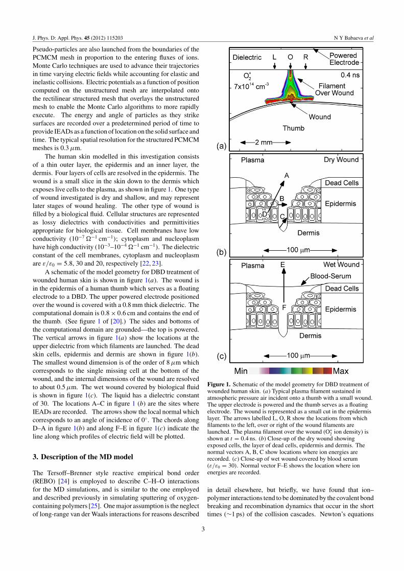
The human skin modelled in this investigation consistsof a thin outer layer, the epidermis and an inner layer, thedermis. Four layers of cells are resolved in the epidermis. Thewound is a small slice in the skin down to the dermis whichexposes live cells to the plasma, as shown in figure 1. One typeof wound investigated is dry and shallow, and may representlater stages of wound healing. The other type of wound isfilled by a biological fluid. Cellular structures are representedas lossy dielectrics with conductivities and permittivitiesappropriate for biological tissue. Cell membranes have lowconductivity (10−7 �−1 cm−1); cytoplasm and nucleoplasmhave high conductivity (10−3–10−4 �−1 cm−1). The dielectricconstant of the cell membranes, cytoplasm and nucleoplasmare ε/ε0 = 5.8, 30 and 20, respectively [22, 23].
A schematic of the model geometry for DBD treatment ofwounded human skin is shown in figure 1(a). The wound isin the epidermis of a human thumb which serves as a floatingelectrode to a DBD. The upper powered electrode positionedover the wound is covered with a 0.8 mm thick dielectric. Thecomputational domain is 0.8 × 0.6 cm and contains the end ofthe thumb. (See figure 1 of [20].) The sides and bottoms ofthe computational domain are grounded—the top is powered.The vertical arrows in figure 1(a) show the locations at theupper dielectric from which filaments are launched. The deadskin cells, epidermis and dermis are shown in figure 1(b).The smallest wound dimension is of the order of 8 µm whichcorresponds to the single missing cell at the bottom of thewound, and the internal dimensions of the wound are resolvedto about 0.5 µm. The wet wound covered by biological fluidis shown in figure 1(c). The liquid has a dielectric constantof 30. The locations A–C in figure 1 (b) are the sites whereIEADs are recorded. The arrows show the local normal whichcorresponds to an angle of incidence of 0◦. The chords alongD–A in figure 1(b) and along F–E in figure 1(c) indicate theline along which profiles of electric field will be plotted.
3. Description of the MD model
The Tersoff–Brenner style reactive empirical bond order(REBO) [24] is employed to describe C–H–O interactionsfor the MD simulations, and is similar to the one employedand described previously in simulating sputtering of oxygen-containing polymers [25]. One major assumption is the neglectof long-range van der Waals interactions for reasons described
Figure 1. Schematic of the model geometry for DBD treatment ofwounded human skin. (a) Typical plasma filament sustained inatmospheric pressure air incident onto a thumb with a small wound.The upper electrode is powered and the thumb serves as a floatingelectrode. The wound is represented as a small cut in the epidermislayer. The arrows labelled L, O, R show the locations from whichfilaments to the left, over or right of the wound filaments arelaunched. The plasma filament over the wound (O+
2 ion density) isshown at t = 0.4 ns. (b) Close-up of the dry wound showingexposed cells, the layer of dead cells, epidermis and dermis. Thenormal vectors A, B, C show locations where ion energies arerecorded. (c) Close-up of wet wound covered by blood serum(ε/ε0 = 30). Normal vector F–E shows the location where ionenergies are recorded.
in detail elsewhere, but briefly, we have found that ion–polymer interactions tend to be dominated by the covalent bondbreaking and recombination dynamics that occur in the shorttimes (∼1 ps) of the collision cascades. Newton’s equations
3
J. Phys. D: Appl. Phys. 45 (2012) 115203 N Y Babaeva et al
of motion are integrated numerically with the velocity Verletalgorithm using a time step of 0.1 fs. The Berendsen thermostatis used to control the system temperature. The initialsimulation cell consists of sets of 36 vertically aligned acylchains (6×6 arrays) of our model lipid A molecules, followingapproximately the structure described by Kato et al [26]. Theacyl chains consist of C15H29O2 and C15H28O3 (attached tobeta hydroxy group), with the ratio of 2 : 1.
The initial surface is constructed from these 36 chainsand is allowed to equilibrate under the simulation procedurefor several tens of picoseconds to yield a relaxed surface at300 K. The dimensions of the simulated film are approximately2.3 nm × 3.6 nm and 6.8 nm deep. The initial density of thefilm was found to match typical polymers (∼0.8 g cm−3). Thelateral boundaries are treated as periodic and the bottom layer(consisting in this case of entire lipid A chains) is initially heldfixed. In order to allow simulations of films deeper than a singleC15 chain, we connect these model lipid A segments togetherand as material is sputtered from the surface, additional chainsare added. This is thought to mimic real films with manylayers of biopolymer present. We note that similar strategiesworked well in simulation of ion sputtering of non-biologicalpolymers [25]. Simulated Ar+ ions are initially placed atrandom positions laterally at a height beyond the cut-off of thepotential, and are directed at normal incidence to the surface.Ions are assumed to be neutralized before impact via Augerprocesses and therefore all species are treated as fast neutrals.A Moliere-type potential is used to model interactions of Arwith all other species. At the end of each impact lastingbetween 0.5 and 10 ps, any sputtered products and remainingAr are removed and the cell is cooled to 300 K. The next ionis launched and the process is repeated until results such asaverage sputtering yield reaches a steady state.
4. IEADs onto dry and wet wounds
We launched positive plasma filaments from locations L (left),O (over) and R (right) from the upper dielectric. Theselocations determine the position of the filament to the left,over or to the right of the wound, respectively, as shown infigure 1(a). The skin is initially uncharged and the DBDvoltage is 40 kV. Typical plasma densities are 1015 cm−3.When the plasma strikes the surface of the thumb, the surfacecharges as in a conventional DBD, resulting in a spreadingof the plasma along the surface, as shown in figure 1(a).This behaviour is very similar to the interaction of DBDswith organic materials, such as hydrocarbon polymers. Thebehaviour and spreading of such filaments is discussed in [17].
When the plasma filament is far from the surface, theelectric field in the tip of the filament is of the order of150–200 kV cm−1. When the filament strikes a surface, inthis case a cell membrane, thereby bridging the gap with aconductive channel, the majority of the applied voltage ismomentarily transferred to the sheath at the surface of thewound. This results in electric fields being many hundredsof kV cm−1 lasting for a few ns. Given these electric fields,with mean free paths of about one-half micron for ions atatmospheric pressure, one might expect ion energies of up to
tens of eV incident onto the membrane surface produced byacceleration in the sheath. (The time to accelerate an oxygenion across its mean free path of 0.5 µm to an energy of 20 eVin an electric field of 400 kV cm−1 is <0.1 ns.)
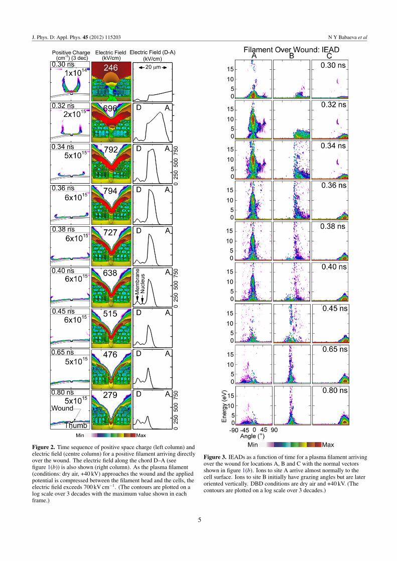
The propagation of the space charge wave in the head ofthe filament in the vicinity of the wound and the electric fieldin the wound for the positive filament directly over the woundare shown in figure 2. The space charge, having densitiesexceeding 6×1015 cm−3, defines the location of the ionizationfront of the filament. After striking the wound, the filamentspreads over the tissue surface with a speed of 5 × 108 cm s−1.With an electron density of nearly 1015 cm−3 and electrontemperature of 3–5 eV, the Debye length λD < 1 µm. As aresult, the plasma is able to penetrate into the wound. A sheathis formed conformal to the surface of the exposed cells, thoughnot into the narrowest feature at the centre of the wound. Asthe filament approaches the wound and electric potential iscompressed between the head of the filament and the exposedcells, the electric field in the sheath exceeds 700 kV cm−1,after which it begins to dissipate. The thickness of the sheathdecreases from 15 µm to 7 µm as the discharge spreads alongthe surface.
The time evolution of IEADs for O+2 onto the cell surfaces
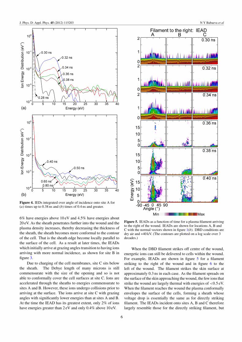
at sites A, B and C is shown in figure 3. The angle integratedion energy distributions (IEDs) for location A are shown infigure 4. Normal vectors to these sites are shown in figure 1(b).Ions incident onto site A arrive nearly normally to the surfaceof the cell. Ions incident onto sites B and C initially havegrazing angles. As the head of the plasma filament approachesthe wound (t < 0.3 ns), the potential is expelled from theconductive channel of the filament and compressed in the spaceahead of the channel and the surface. Ions incident onto thewound are mostly produced by photoionization ahead of theionization front and are accelerated in this enhanced field. Ionenergies are 0.1–1 eV. These energies are commensurate withthe effective equilibrium drift temperature of oxygen ions inthe vacuum fields [27]. As the ionization front enters into thewound and the sheath is formed at the surface of the cells,the ion energies onto the cells increase. At site A, whosesurface normal is nearly vertical, the bulk of the IEAD extendsto 15 eV at 0.32 ns with a tail that extends to nearly 100 eVcorresponding to the peak electric field of> 700 kV cm−1. Theepithermal ions (energies � 1 eV) have essentially isotropicangles of incidents. At the time when the tail of the IEADextends to the highest energy (0.34 ns) 14% of ions haveenergies above 2 eV, 12% above 5 eV, 8% above 10 eV and5% above 20 eV. The angle of incidence of ions above 1 eV is±20◦. The IEAD begins to degrade in energy as the sheathspreads and the sheath voltage diminishes. However, there isstill a substantial tail to the IEAD that extends above 40 eV.
The IEADs incident onto site B have nearly the samethermal component as site A and the ions have nearly the samemaximum extent in energy, however, the ions initially arrive atgrazing angles. Since the length of the chord for ions to travelthrough the sheath to arrive at Site B is longer than for site A,the ions are moderately more collisional, and so the thermalcomponent is larger. At the time that the tail of the IEADextends to its greatest energy, 11% have energies above 2 eV,
4
J. Phys. D: Appl. Phys. 45 (2012) 115203 N Y Babaeva et al
Figure 2. Time sequence of positive space charge (left column) andelectric field (centre column) for a positive filament arriving directlyover the wound. The electric field along the chord D–A (seefigure 1(b)) is also shown (right column). As the plasma filament(conditions: dry air, +40 kV) approaches the wound and the appliedpotential is compressed between the filament head and the cells, theelectric field exceeds 700 kV cm−1. (The contours are plotted on alog scale over 3 decades with the maximum value shown in eachframe.)
Figure 3. IEADs as a function of time for a plasma filament arrivingover the wound for locations A, B and C with the normal vectorsshown in figure 1(b). Ions to site A arrive almost normally to thecell surface. Ions to site B initially have grazing angles but are lateroriented vertically. DBD conditions are dry air and +40 kV. (Thecontours are plotted on a log scale over 3 decades.)
5
J. Phys. D: Appl. Phys. 45 (2012) 115203 N Y Babaeva et al
Figure 4. IEDs integrated over angle of incidence onto site A for(a) times up to 0.38 ns and (b) times of 0.4 ns and greater.
6% have energies above 10 eV and 4.5% have energies about20 eV. As the sheath penetrates further into the wound and theplasma density increases, thereby decreasing the thickness ofthe sheath, the sheath becomes more conformal to the contourof the cell. That is the sheath edge become locally parallel tothe surface of the cell. As a result at later times, the IEADswhich initially arrive at grazing angles transition to having ionsarriving with more normal incidence, as shown for site B infigure 3.
Due to charging of the cell membranes, site C sits belowthe sheath. The Debye length of many microns is stillcommensurate with the size of the opening and so is notable to conformally cover the cell surfaces at site C. Ions areaccelerated through the sheaths to energies commensurate tosites A and B. However, these ions undergo collisions prior toarriving at the surface. The ions arrive at site C with grazingangles with significantly lower energies than at sites A and B.At the time the IEAD has its greatest extent, only 2% of ionshave energies greater than 2 eV and only 0.4% above 10 eV.
Figure 5. IEADs as a function of time for a plasma filament arrivingto the right of the wound. IEADs are shown for locations A, B andC with the normal vectors shown in figure 1(b). DBD conditions aredry air and +40 kV. (The contours are plotted on a log scale over 3decades.)
When the DBD filament strikes off centre of the wound,energetic ions can still be delivered to cells within the wound.For example, IEADs are shown in figure 5 for a filamentstriking to the right of the wound and in figure 6 to theleft of the wound. The filament strikes the skin surface atapproximately 0.3 ns in each case. As the filament spreads onthe surface of the skin approaching the wound, the few ions thatstrike the wound are largely thermal with energies of <0.5 eV.When the filament reaches the wound the plasma conformallyenvelopes the surface of the cells, forming a sheath whosevoltage drop is essentially the same as for directly strikingfilament. The IEADs incident onto sites A, B and C thereforelargely resemble those for the directly striking filament, but
6
J. Phys. D: Appl. Phys. 45 (2012) 115203 N Y Babaeva et al
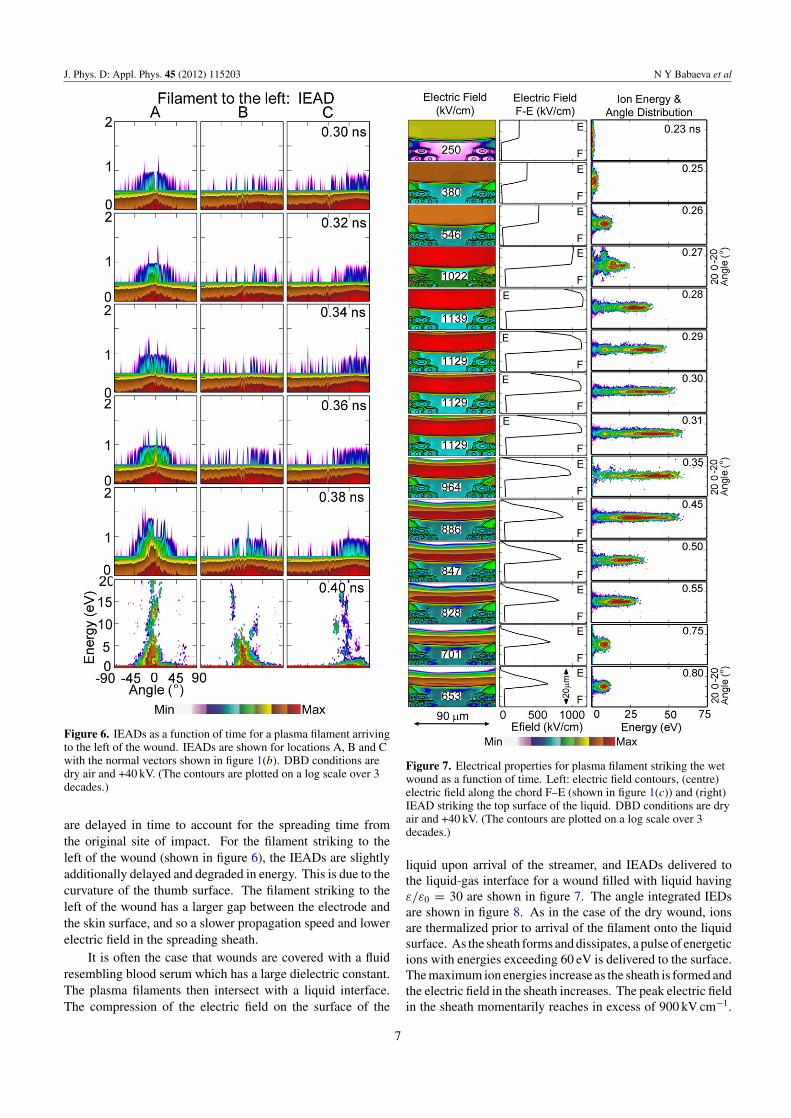
Figure 6. IEADs as a function of time for a plasma filament arrivingto the left of the wound. IEADs are shown for locations A, B and Cwith the normal vectors shown in figure 1(b). DBD conditions aredry air and +40 kV. (The contours are plotted on a log scale over 3decades.)
are delayed in time to account for the spreading time fromthe original site of impact. For the filament striking to theleft of the wound (shown in figure 6), the IEADs are slightlyadditionally delayed and degraded in energy. This is due to thecurvature of the thumb surface. The filament striking to theleft of the wound has a larger gap between the electrode andthe skin surface, and so a slower propagation speed and lowerelectric field in the spreading sheath.
It is often the case that wounds are covered with a fluidresembling blood serum which has a large dielectric constant.The plasma filaments then intersect with a liquid interface.The compression of the electric field on the surface of the
Figure 7. Electrical properties for plasma filament striking the wetwound as a function of time. Left: electric field contours, (centre)electric field along the chord F–E (shown in figure 1(c)) and (right)IEAD striking the top surface of the liquid. DBD conditions are dryair and +40 kV. (The contours are plotted on a log scale over 3decades.)
liquid upon arrival of the streamer, and IEADs delivered tothe liquid-gas interface for a wound filled with liquid havingε/ε0 = 30 are shown in figure 7. The angle integrated IEDsare shown in figure 8. As in the case of the dry wound, ionsare thermalized prior to arrival of the filament onto the liquidsurface. As the sheath forms and dissipates, a pulse of energeticions with energies exceeding 60 eV is delivered to the surface.The maximum ion energies increase as the sheath is formed andthe electric field in the sheath increases. The peak electric fieldin the sheath momentarily reaches in excess of 900 kV cm−1.
7
J. Phys. D: Appl. Phys. 45 (2012) 115203 N Y Babaeva et al
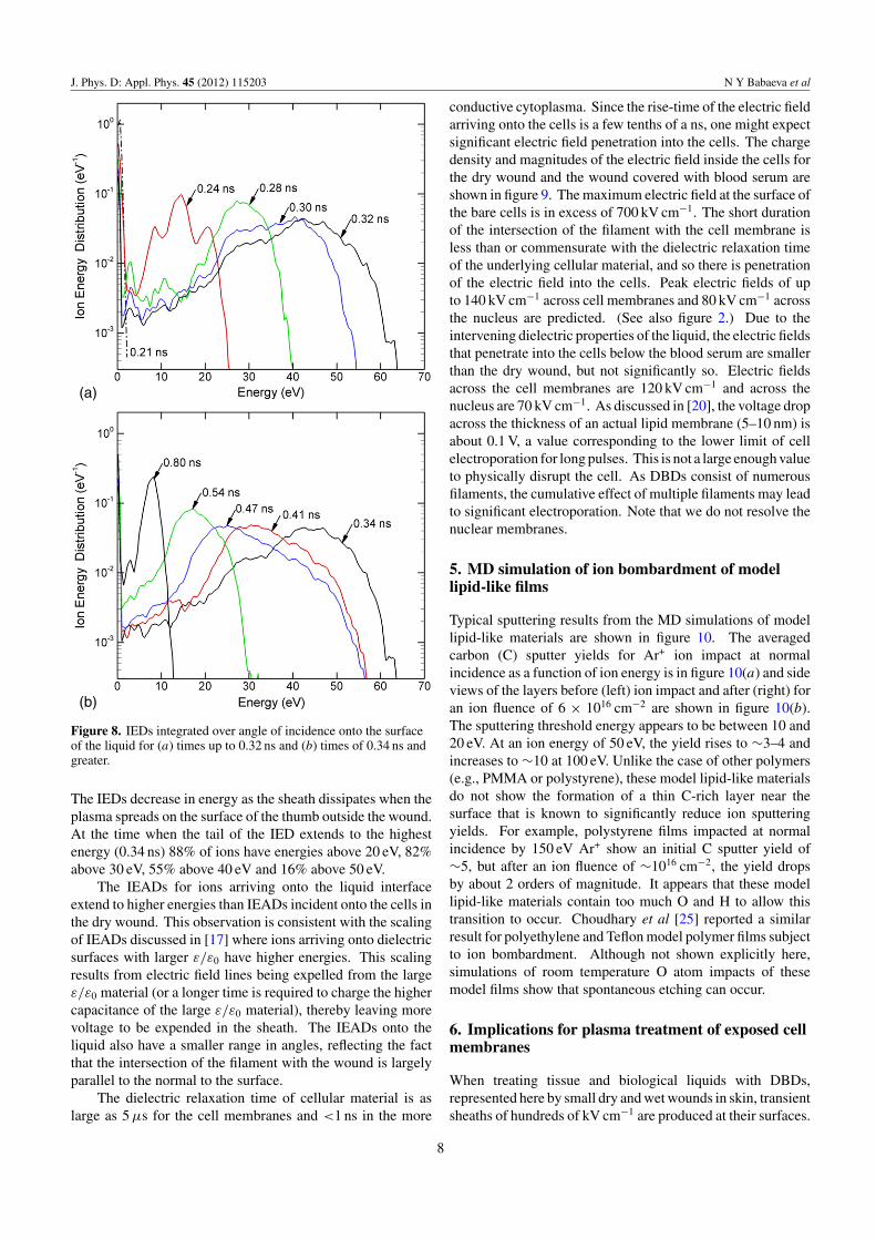
Figure 8. IEDs integrated over angle of incidence onto the surfaceof the liquid for (a) times up to 0.32 ns and (b) times of 0.34 ns andgreater.
The IEDs decrease in energy as the sheath dissipates when theplasma spreads on the surface of the thumb outside the wound.At the time when the tail of the IED extends to the highestenergy (0.34 ns) 88% of ions have energies above 20 eV, 82%above 30 eV, 55% above 40 eV and 16% above 50 eV.
The IEADs for ions arriving onto the liquid interfaceextend to higher energies than IEADs incident onto the cells inthe dry wound. This observation is consistent with the scalingof IEADs discussed in [17] where ions arriving onto dielectricsurfaces with larger ε/ε0 have higher energies. This scalingresults from electric field lines being expelled from the largeε/ε0 material (or a longer time is required to charge the highercapacitance of the large ε/ε0 material), thereby leaving morevoltage to be expended in the sheath. The IEADs onto theliquid also have a smaller range in angles, reflecting the factthat the intersection of the filament with the wound is largelyparallel to the normal to the surface.
The dielectric relaxation time of cellular material is aslarge as 5 µs for the cell membranes and <1 ns in the more
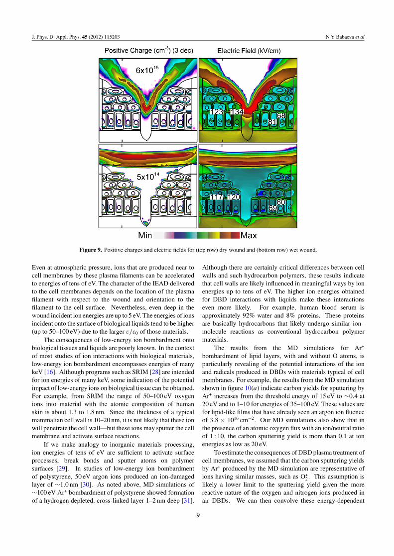
conductive cytoplasma. Since the rise-time of the electric fieldarriving onto the cells is a few tenths of a ns, one might expectsignificant electric field penetration into the cells. The chargedensity and magnitudes of the electric field inside the cells forthe dry wound and the wound covered with blood serum areshown in figure 9. The maximum electric field at the surface ofthe bare cells is in excess of 700 kV cm−1. The short durationof the intersection of the filament with the cell membrane isless than or commensurate with the dielectric relaxation timeof the underlying cellular material, and so there is penetrationof the electric field into the cells. Peak electric fields of upto 140 kV cm−1 across cell membranes and 80 kV cm−1 acrossthe nucleus are predicted. (See also figure 2.) Due to theintervening dielectric properties of the liquid, the electric fieldsthat penetrate into the cells below the blood serum are smallerthan the dry wound, but not significantly so. Electric fieldsacross the cell membranes are 120 kV cm−1 and across thenucleus are 70 kV cm−1. As discussed in [20], the voltage dropacross the thickness of an actual lipid membrane (5–10 nm) isabout 0.1 V, a value corresponding to the lower limit of cellelectroporation for long pulses. This is not a large enough valueto physically disrupt the cell. As DBDs consist of numerousfilaments, the cumulative effect of multiple filaments may leadto significant electroporation. Note that we do not resolve thenuclear membranes.
5. MD simulation of ion bombardment of modellipid-like films
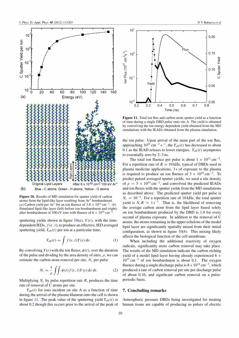
Typical sputtering results from the MD simulations of modellipid-like materials are shown in figure 10. The averagedcarbon (C) sputter yields for Ar+ ion impact at normalincidence as a function of ion energy is in figure 10(a) and sideviews of the layers before (left) ion impact and after (right) foran ion fluence of 6 × 1016 cm−2 are shown in figure 10(b).The sputtering threshold energy appears to be between 10 and20 eV. At an ion energy of 50 eV, the yield rises to ∼3–4 andincreases to ∼10 at 100 eV. Unlike the case of other polymers(e.g., PMMA or polystyrene), these model lipid-like materialsdo not show the formation of a thin C-rich layer near thesurface that is known to significantly reduce ion sputteringyields. For example, polystyrene films impacted at normalincidence by 150 eV Ar+ show an initial C sputter yield of∼5, but after an ion fluence of ∼1016 cm−2, the yield dropsby about 2 orders of magnitude. It appears that these modellipid-like materials contain too much O and H to allow thistransition to occur. Choudhary et al [25] reported a similarresult for polyethylene and Teflon model polymer films subjectto ion bombardment. Although not shown explicitly here,simulations of room temperature O atom impacts of thesemodel films show that spontaneous etching can occur.
6. Implications for plasma treatment of exposed cellmembranes
When treating tissue and biological liquids with DBDs,represented here by small dry and wet wounds in skin, transientsheaths of hundreds of kV cm−1 are produced at their surfaces.
8
J. Phys. D: Appl. Phys. 45 (2012) 115203 N Y Babaeva et al
Figure 9. Positive charges and electric fields for (top row) dry wound and (bottom row) wet wound.
Even at atmospheric pressure, ions that are produced near tocell membranes by these plasma filaments can be acceleratedto energies of tens of eV. The character of the IEAD deliveredto the cell membranes depends on the location of the plasmafilament with respect to the wound and orientation to thefilament to the cell surface. Nevertheless, even deep in thewound incident ion energies are up to 5 eV. The energies of ionsincident onto the surface of biological liquids tend to be higher(up to 50–100 eV) due to the larger ε/ε0 of those materials.
The consequences of low-energy ion bombardment ontobiological tissues and liquids are poorly known. In the contextof most studies of ion interactions with biological materials,low-energy ion bombardment encompasses energies of manykeV [16]. Although programs such as SRIM [28] are intendedfor ion energies of many keV, some indication of the potentialimpact of low-energy ions on biological tissue can be obtained.For example, from SRIM the range of 50–100 eV oxygenions into material with the atomic composition of humanskin is about 1.3 to 1.8 nm. Since the thickness of a typicalmammalian cell wall is 10–20 nm, it is not likely that these ionwill penetrate the cell wall—but these ions may sputter the cellmembrane and activate surface reactions.
If we make analogy to inorganic materials processing,ion energies of tens of eV are sufficient to activate surfaceprocesses, break bonds and sputter atoms on polymersurfaces [29]. In studies of low-energy ion bombardmentof polystyrene, 50 eV argon ions produced an ion-damagedlayer of ∼1.0 nm [30]. As noted above, MD simulations of∼100 eV Ar+ bombardment of polystyrene showed formationof a hydrogen depleted, cross-linked layer 1–2 nm deep [31].
Although there are certainly critical differences between cellwalls and such hydrocarbon polymers, these results indicatethat cell walls are likely influenced in meaningful ways by ionenergies up to tens of eV. The higher ion energies obtainedfor DBD interactions with liquids make these interactionseven more likely. For example, human blood serum isapproximately 92% water and 8% proteins. These proteinsare basically hydrocarbons that likely undergo similar ion–molecule reactions as conventional hydrocarbon polymermaterials.
The results from the MD simulations for Ar+
bombardment of lipid layers, with and without O atoms, isparticularly revealing of the potential interactions of the ionand radicals produced in DBDs with materials typical of cellmembranes. For example, the results from the MD simulationshown in figure 10(a) indicate carbon yields for sputtering byAr+ increases from the threshold energy of 15 eV to ∼0.4 at20 eV and to 1–10 for energies of 35–100 eV. These values arefor lipid-like films that have already seen an argon ion fluenceof 3.8 × 1016 cm−2. Our MD simulations also show that inthe presence of an atomic oxygen flux with an ion/neutral ratioof 1 : 10, the carbon sputtering yield is more than 0.1 at ionenergies as low as 20 eV.
To estimate the consequences of DBD plasma treatment ofcell membranes, we assumed that the carbon sputtering yieldsby Ar+ produced by the MD simulation are representative ofions having similar masses, such as O+
2. This assumption islikely a lower limit to the sputtering yield given the morereactive nature of the oxygen and nitrogen ions produced inair DBDs. We can then convolve these energy-dependent
9
J. Phys. D: Appl. Phys. 45 (2012) 115203 N Y Babaeva et al
Figure 10. Results of MD simulation for sputter yield of carbonatoms from the lipid-like layer resulting from Ar+ bombardment.(a) Carbon yield per Ar+ for an ion fluence of 3.8 × 1016 cm−2. (b)Simulated lipid-like layer (left) before ion bombardment and (right)after bombardment of 100 eV ions with fluence of 6 × 1016 cm−2.
sputtering yields shown in figure 10(a), Y (ε), with the time-dependent IEDs, f (ε, t), to produce an effective, IED averagedsputtering yield, Yeff(t) per ion at a particular time,
Yeff(t) =∫
f (ε, t)Y (ε) dε. (1)
By convolving Y (ε) with the ion fluxes, φ(t), over the durationof the pulse and dividing by the area density of sites, ρ, we canestimate the carbon atom removal per site, Nc per pulse
Nc = 1
ρ
∫ ∫φ(t)f (ε, t)Y (ε) dε dt . (2)
Multiplying Nc by pulse repetition rate R, produces the timerate of removal of C atoms per site.
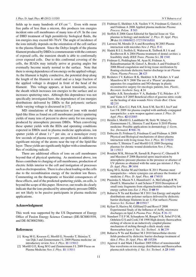
Yeff(t) for ions incident on site A as a function of timeduring the arrival of the plasma filament onto the cell is shownin figure 11. The peak value of the sputtering yield Yeff(t) isabout 0.2 though this occurs prior to the arrival of the peak of
Figure 11. Total ion flux and carbon atom sputter yield as a functionof time during a single DBD pulse onto site A. The yield is obtainedby convolving the ion energy-dependent yield obtained from the MDsimulations with the IEADs obtained from the plasma simulation.
the ion pulse. Upon arrival of the main part of the ion flux,approaching 1022 cm−2 s−1, the Yeff(t) has decreased to about0.1 as the IEAD relaxes to lower energies. Yeff(t) asymptotesto essentially zero by 2–3 ns.
The total ion fluence per pulse is about 1 × 1012 cm−2.For a repetition rate of R = 10 kHz, typical of DBDs used inplasma medicine applications, 3 s of exposure to the plasmais required to produce an ion fluence of 3 × 1016 cm−2. Topredict pulsed averaged sputter yields, we used a site densityof ρ = 5 × 1014 cm−2, and convolved the predicted IEADsand ion fluxes with the sputter yields from the MD simulationsas described above. The predicted sputter yield per pulse isNc = 10−4. For a repetition rate of 10 kHz, the total sputteryield is NcR ≈ 1 s−1. That is, the likelihood of removingthe average carbon atom from the lipid layer based solelyon ion bombardment produced by the DBD is 1.0 for everysecond of plasma exposure. In addition to the removal of Catoms, the atoms remaining in the upper echelons of the modellipid layer are significantly spatially mixed from their initialconfiguration, as shown in figure 10(b). This mixing likelyaffects the biological function of the cell membrane.
When including the additional reactivity of oxygenradicals, significantly more carbon removal may take place.The results of the MD simulation indicate the carbon etchingyield of a model lipid layer having already experienced 6 ×1015 cm−2 of ion bombardment is about 0.1. The oxygenfluence during a single discharge pulse is 8×1014 cm−2, whichproduced a rate of carbon removal per site per discharge pulseof about 0.16, and significant carbon removal on a pulse-periodic basis.
7. Concluding remarks
Atmospheric pressure DBDs being investigated for treatinghuman tissue are capable of producing ns pulses of electric
10
J. Phys. D: Appl. Phys. 45 (2012) 115203 N Y Babaeva et al
fields up to many hundreds of kV cm−1. Even with meanfree paths of less than a micron, this produces ion energiesincident onto cell membranes of many tens of eV. In the caseof DBD treatment of high permittivity biological fluids, theion energies may exceed 60–70 eV. The angle of incidence ofthe ions initially depends on the orientation of the cell surfaceto the plasma filament. Since the Debye length of the plasmafilament produced by DBDs is commensurate with the contoursof exposed cells, the transient sheath is able to conformallycover exposed cells. Due to this conformal covering of thecells, the IEADs may initially arrive at grazing angles buteventually become nearly normal to the surface. Note thatthere is strong dependence of ion energy on the applied voltage.As the filament is highly conductive, the potential drop alongthe length of the filament is small and so a large fraction ofthe applied voltage is dropped in front of the head of thefilament. This voltage appears, at least transiently, acrossthe sheath which increases ion energies to the surface and soincreases sputtering rates. Although this dependence was notspecifically investigated here, the dependence of ion energiesdistributions delivered by DBDs to flat polymeric surfaceswhile varying voltage is discussed in [17].
MD simulations of the interaction of ions with modellipid-like films as found on cell membranes predict sputteringyields of many tens of percent to above unity for ion energiesproduced by atmospheric pressure DBDs. When convolvingthese sputter yields with the IEDs and operating conditionsexpected in DBDs used in plasma medicine applications, ionsputter yields of about 1 s−1 per site, or a monolayer everyfew seconds of plasma exposure, are predicted in addition tosignificant mixing of the atoms near the top of the lipid-likelayer. These yields are significantly higher with a simultaneousflux of oxidizing radicals.
There are additional effects of ions on cell membranesbeyond that of physical sputtering. As mentioned above, ionfluxes contribute to charging of cell membranes, production ofelectric fields interior to the cell and instigation of processessuch as electroporation. There is also a heat loading on the cellsdue to the recombination energy of the incident ion fluxes.Commenting on the therapeutic or biocidal consequences ofthese effects, and of the predicted sputtering yields, on cells, isbeyond the scope of this paper. However, our results do clearlyindicate that the ions produced by atmospheric pressure DBDsare not likely to be passive participants in plasma medicineapplications.
Acknowledgment
This work was supported by the US Department of EnergyOffice of Fusion Energy Science Contract (DE-SC0001939,and DE-SC0002588).
References
[1] Kong M G, Kroesen G, Morfill G, Nosenko T, Shimizu T,van Dijk J and Zimmermann J L 2009 Plasma medicine: anintroductory review New J. Phys. 11 115012
[2] Morfill G E, Kong M G and Zimmermann J L 2009 Focus onPlasma Medicine New J. Phys. 11 115011
[3] Fridman G, Shekhter A B, Vasilets V N, Friedman G, Gutsol Aand Fridman A 2008 Applied plasma medicine PlasmaProcess. Polym. 5 503
[4] Stoffels E 2006 Guest Editorial for Special Issue on ‘Gasplasmas in biology and medicine’ J. Phys. D: Appl. Phys.39 doi:10.1088/0022-3727/39/16/E01
[5] Laroussi M, Mendis D A and Rosenberg M 2003 Plasmainteraction with microbes New J. Phys. 5 41
[6] Sladek R E J, Stoffels E, Walraven R, Tielbeek R J A andKoolhoven R A 2004 Plasma treatment of dental cavities: afeasibility study IEEE Trans. Plasma Sci. 32 1540
[7] Fridman G, Peddinghaus M, Ayan H, Fridman A,Balasubramanian M, Gutsol A, Brooks A and Friedman G2006 Blood coagulation and living tissue sterilization byfloating-electrode dielectric barrier discharge in air PlasmaChem. Plasma Process. 26 425
[8] Reshetov I V, Kabisov R K, Shekhter A B, Pekshev A V andManeilova M V 2000 The use of a ‘Plason’ air-plasmaapparatus for coagulation and NO-therapy in plasticreconstructive surgery for oncologic patients Ann. Plastic,Reconstr. Aesthetic Surg. 4 24
[9] Shekhte A B, Serezhenkov V A, Rudenko T G, Pekshev A Vand Vanin A F 2005 Beneficial effect of gaseous nitric oxideon the healing of skin wounds Nitric Oxide-Biol. Chem.12 210
[10] Kim G C, Kim G J, Park S R, Jeon S M, Seo H J, Iza F andLee J K 2009 Air plasma coupled with antibody-conjugatednanoparticles: a new weapon against cancer J. Phys. D:Appl. Phys. 42 032005
[11] Heinlin J, Morfill G, Landthaler M, Stolz W, Isbary G,Zimmermann J L, Shimizu T and Karrer S 2010 Plasmamedicine: Possible applications in dermatology J. Germ.Soc. Dermatol. 8 968–76
[12] Dobrynin D, Fridman G, Friedman G and Fridman A 2009Physical and Biological mechanisms of direct plasmainteraction with living tissue New J. Phys. 11 115020
[13] Nosenko T, Shimizu T and Morfill G E 2009 Designingplasmas for chronic wound disinfection New J. Phys.11 115013
[14] Boudam M K, Moisan M, Saoudi B, Popovici C, Gherardi Nand Massines F 2006 Bacterial spore inactivation byatmospheric-pressure plasmas in the presence or absence ofUV photons as obtained with the same gas mixture J. Phys.D: Appl. Phys. 39 3494
[15] Kong M G, Keidar M and Ostrikov K 2011 Plasmas meetnanoparticles—where synergies can advance the frontier ofmedicine J. Phys. D: Appl. Phys. 44 174018
[16] Ptasinska S, Mason N J, Hunniford C A, McCullough R W,Denifl S, Mauracher A and Scheier P 2010 Desorption ofsmall ionic fragments from oligonucleotides induced by lowenergy carbon ions Eur. J. Phys. D 60 59
[17] Babaeva N Yu and Kushner M J 2011 Ion Energy and angulardistributions onto polymer surfaces delivered by dielectricbarrier discharge filaments in air: I. Flat surfaces PlasmaSources Sci. Technol. 20 035017
[18] Kylian O, Hasiwa M, Gilliland D and Rossi F 2008Experimental Study of the Influence of Ar/H2 microwavedischarges on lipid A Plasma Proc. Polym. 5 26–32
[19] Standaert T E F M, Schaepkens M, Rueger N R, Sebel P G M,Oehrlein G S and Cook J M 1998 High density fluorocarbonetching of silicon in an inductively coupled plasma:mechanism of etching through a thick steady statefluorocarbon layer J. Vac. Sci. Technol. A 16 239
[20] Babaeva N Yu and Kushner M J 2010 Intracellular electricfields produced by dielectric barrier discharge treatment ofskin J. Phys. D: Appl. Phys. 43 185206
[21] Agarwal A and Mark J Kushner 2005 Effect of nonsinusoidalbias waveforms on ion energy distributions and fluorocarbonplasma etch selectivity J. Vac. Sci. Technol. A 23 1440
11

J. Phys. D: Appl. Phys. 45 (2012) 115203 N Y Babaeva et al
[22] Feldman Y, Ermolina I and Hayashi Y 2003 Time domaindielectric spectroscopy study of biological systems IEEETrans. Dielectr. Electr. Insul. 10 728
[23] Ermolina I, Polevaya Y, Feldman Y, Ginzburg B andSchlesinger M 2001 Study of normal and malignant whiteblood cells by time domain dielectric spectroscopy IEEETrans. Dielectr. Electr. Insul. 8 253
[24] Ni B, Lee K H and Sinnott S B 2004 A reactiveempirical bond order (REBO) potential forhydrocarbon–oxygen interactions J. Phys.: Condens. Matter16 7261
[25] Choudhary G K, Vegh J J and Graves D B 2009 Moleculardynamics simulations of oxygen-containing polymersputtering and the Ohnishi parameter J. Appl. Phys. D:Appl. Phys. 42 242001
[26] Kato N, Sugiyama T, Naito S, Arakawa Y, Ito H, Kido N,Ohta M and Sasaki K 2000 Molecular structure of bacterialendotoxin (Escherichia coli Re lipopolysaccharide):implications for formation of a novel heterogeneous latticestructure Mol. Microbiol. 36 796
[27] Mason E A and Daniel E W 1988 Transport Properties of Ionsin Gases (New York: Wiley)
[28] SRIM 2008 (Stopping and Range of Ions in Matter)SRIM-2008, http://www.srim.org/
[29] Oehrlein G S, Phaneuf R J and Graves D B 2011Plasma–polymer interactions: a review of progress inunderstanding polymer resist mask durability during plasmaetching for nanoscale fabrication J. Vac. Sci. Technol. B29 010801
[30] Bruce R L, Weilnboeck F, Lin T, Phaneuf R J, Oehrlein G S,Long B K, Willson C G, Vegh J J, Nest D and Graves D B2010 Relationship between nanoscale roughness andion-damaged layer in argon plasma exposed polystyrenefilms J. Appl. Phys. 107 084310
[31] Vegh J J, Nest D, Graves D B, Bruce R L, Engelmann S,Kwon T, Phaneuf R J, Oehrlein G S, Long B K andWillson C G 2008 Molecular dynamics simulations ofnear-surface modification of polystyrene: bombardmentwith Ar+ and Ar+/radical chemistries J. Appl. Phys.104 034308
12