Ion Acceleration by Radiation Pressure in Thick and Thin ... · Andrea Macchi CNR/INFM/polyLAB and...
78
Andrea Macchi CNR/INFM/polyLAB and Dipartimento di Fisica “Enrico Fermi”, Università di Pisa,Italy Ion Acceleration by Radiation Pressure in Thick and Thin Targets COULOMB09 Workshop, Senigallia, June 16, 2009
Transcript of Ion Acceleration by Radiation Pressure in Thick and Thin ... · Andrea Macchi CNR/INFM/polyLAB and...

Andrea Macchi
CNR/INFM/polyLAB and
Dipartimento di Fisica “Enrico Fermi”, Università di Pisa,Italy
Ion Acceleration by Radiation Pressure in Thick and Thin Targets
COULOMB09 Workshop, Senigallia, June 16, 2009

Contributors
Silvia Veghini, Sara Tuveri,Francesco Pegoraro
Dipartimento di Fisica “Enrico Fermi”, Università di Pisa and CNISM, Italy
Tatiana V. Liseikina
Max Planck Institute for Nuclear Physics,Heidelberg, Germany
Carlo Benedetti
Dipartimento di Fisica, Università di Bologna and INFN, Italy

- Ion acceleration by Radiation Pressure Acceleration
(using Circularly Polarized pulses):
the thick (“Hole Boring”) and thin target (“Light Sail”) regimes
- thick targets: acceleration with few-cycle pulses and
preplasma effects
- thin targets: the “Light Sail” (accelerating mirror) model
revisited
Outline

Why Circular Polarization?
Using CP and normal incidence (an experimentalist's nightmare...) fast electron generation by the jXB force is strongly suppressed, maximizing radiation pressure and obtaining a “smooth” acceleration of the bulk target
A.Macchi et al, Phys.Rev.Lett. 94 (2005) 165003
Studies of thick (semi-infinite) targets (“Hole Boring”):
T.V.Liseikina & A.Macchi, Appl.Phys.Lett. 94 (2007) 165003;N.Naumova et al, Phys.Rev.Lett. 102 (2009) 025002;A.P.L.Robinson et al, Plasma Phys.Contr.Fus. 51 (2009) 024004.
Studies of ultrathin (sub-wavelength) targets (“Light sail”):
X.Zhang et al, Phys. Plasmas 14 (2007) 073101 & 123108; A.P.L.Robinson et al, New J. Phys. 10 (2008) 013201;O.Klimo et al, Phys. Rev. ST-AB 11 (2008) 031301;X.Q.Yan et al, Phys.Rev.Lett. 100, (2008) 135003 ;B.Qiao et al, Phys.Rev.Lett. 102 (2009) 145002;V.K.Tripathi et al, Plasma Phys.Contr.Fus. 51 (2009) 024014.

Why Circular Polarization?
Using CP and normal incidence (an experimentalist's nightmare...) fast electron generation by the jXB force is strongly suppressed, maximizing radiation pressure and obtaining a “smooth” acceleration of the bulk target
A.Macchi et al, Phys.Rev.Lett. 94 (2005) 165003
Variations on the CP theme (side effects, structured targets, optimization studies ...)
T.V.Liseikina et al, Plasma Phys.Contr.Fus. 50 (2008) 124033;S.G.Rykovanov et al., New J. Phys. 10, (2008) 113005;L.Ji et al, Phys.Rev.Lett. 101 (2008) 164802;Y.Yin et al, Phys.Plasmas 15 (2008) 093106; A.R.Holkundkara and N.K.Gupta, Phys.Plasmas 15 (2008) 123104;M.Chen et al, Phys.Plasmas 15 (2008) 113103;X.Zhang et al, PRST-AB 12 (2009) 021301;A.A.Gonoskov et al, Phys.Rev.Lett. 102 (2009) 145002;X.Q.Yan et al, arXiv:0903.4584;M.Chen et al, arXiv: 0903.3567.
Experimental investigations are highly desired!!!

Why Circular Polarization?
Using CP and normal incidence (an experimentalist's nightmare...) fast electron generation by the jXB force is strongly suppressed, maximizing radiation pressure and obtaining a “smooth” acceleration of the bulk target
A.Macchi et al, Phys.Rev.Lett. 94 (2005) 165003
Variations on the CP theme (side effects, structured targets, optimization studies ...)
T.V.Liseikina et al, Plasma Phys.Contr.Fus. 50 (2008) 124033;S.G.Rykovanov et al., New J. Phys. 10, (2008) 113005;L.Ji et al, Phys.Rev.Lett. 101 (2008) 164802;Y.Yin et al, Phys.Plasmas 15 (2008) 093106; A.R.Holkundkara and N.K.Gupta, Phys.Plasmas 15 (2008) 123104;M.Chen et al, Phys.Plasmas 15 (2008) 113103;X.Zhang et al, PRST-AB 12 (2009) 021301;A.A.Gonoskov et al, Phys.Rev.Lett. 102 (2009) 145002;X.Q.Yan et al, arXiv:0903.4584;M.Chen et al, arXiv: 0903.3567.
Experimental investigations now coming!!!(LIBRA experiment at GEMINI, MBI experiment, ...)

Laser penetration discriminates thick vs. thin targets
In the early stage the laser pulse penetrates into the target creating an electron depletion (0<x<d ) and an electron compression (d<x<d+l
s ) layer
A balance between the electrostatic field E
x
and the ponderomotive force (=local radiation pressure)is established.

In the early stage the laser pulse penetrates into the target creating an electron depletion (0<x<d ) and an electron compression (d<x<d+l
s ) layer
A balance between the electrostatic field E
x
and the ponderomotive force (=local radiation pressure)is established.
Laser penetration discriminates thick vs. thin targets
Ions in this layer d<x<d+l
sare accelerated
“by RPA” (actually by the electric field
balancing theradiation pressure
on electrons)

In the early stage the laser pulse penetrates into the target creating an electron depletion (0<x<d ) and an electron compression (d<x<d+l
s ) layer
A balance between the electrostatic field E
x
and the ponderomotive force (=local radiation pressure)is established.
Laser penetration discriminates thick vs. thin targets
Ions in the “front” layer ofelectron depletion
0<x<dare accelerated by theirown space-charge field
(Coulomb explosion)and do not reach “RPA”
ions

“Hole boring” and thick vs. thin targets
A simple modeling for RPA of semi-infinite targets (“hole boring” regime) accounts for the dynamics observed in PIC data and gives scalings for ion energy and acceleration time
Macchi et al, PRL 94 (2005) 165003
The faster ions originate from the layer d<x<d+l
s (l
s≈c/2
p)
The ions pile up at x≈d+ls and there
“wavebreaking” and bunchformation occurs.
A “thin” target shouldend here, i.e
have a thicknessℓ≈d+l
s in order to
allow “repeated”acceleration of the
“fast” ion layer

Thick Targets:“Hole Boring” Acceleration
with Few-Cycle Pulses

Scaling laws in the hole boring regime
“Piston parameter”
Cut-off velocity and energyfor non-relativistic ions[A.Macchi et al, PRL 94 (2005) 165003]
Relativistic corrections accounting for laser energy depletion in the Lab frame[A.P.L.Robinson et al, PPCF 51 (2009) 024004]

Hole Boring: Pro et Contra
- Ion energy scales with intensity, not with pulse energy
- For solid-densities only a few MeV energies may be obtained (maybe not sufficient even to cross the target!)
BUT - with respect to “Light Sail” (requiring ultrathin targets) the scheme seems more robust and less prone to, e.g., prepulse effects
- HB works in “preplasma”: lower densities boost ion energy [Liseikina, Borghesi, Macchi, Tuveri, PPCF 50 (2008) 124033]
- if a moderately overdense gas or liquid jet can be used asa target, higher energies may be obtained in combination with high repetition rate - gas jet with CO2 laser? (collaboration with A.Sgattoni et al.) - liquid hydrogen jet with Ti:Sa laser?

Hole Boring Acceleration with Few-Cycle Pulses
Future laser systems may produce few-cycle pulses with intensities >1022 W/cm2 and high repetition rate
Such short pulses could “concentrate” all their energy into the acceleration of a single ion bunch
In combination with a liquid hydrogen jet they could provide an efficient, high repetition rate source of multi-MeV protons
Case study:
Hydrogen slab with ne =50n
c =8.6 X 1022 cm3
CP laser pulse with =0.8m and 2 cycles duration (FWHM)Peak intensity I=4.9 X 10²² W/cm2 (a
0 =106)
(suggestion by M.Borghesi & M.Zepf, QUB, Belfast)

The ion spectrum is improved by a density gradient
Step-like density profiles:- multiple ion bunches- multiple peaks in the ion spectrum, cut-off energy at ~140 MeV
(bunch production time is less than laser cycle)
Inhomogeneous density profile (3m preplasma):- single bunch produced- spectrum dominated by single peak at ~180 MeV, <10% energy spread

Circular Polarization stabilizes CE phase effects
Laser-matter interactionwith few-cycle pulses is sensitive to the Carrier-Envelope phase :
E(t)=f(t)sin(t+)
For linearly polarized pulses the ion spectrum is broadand strongly dependent on :
For circular polarization,there is almost no dependence on
because |E(t)|2 isconstant in this case

2D simulations with the AlaDyn code
(C.Benedetti et al.)
ne =50n
c
H slab4 preplasma
CP Gaussian pulse 2X2a
0 =106

2D simulations with the AlaDyn code
(C.Benedetti et al.)
ne =50n
c
H slab4 preplasma
CP Gaussian pulse 2X2a
0 =106

2D simulations with the AlaDyn code
(C.Benedetti et al.)
ne =50n
c
H slab4 preplasma
CP Gaussian pulse 2X2a
0 =106

2D simulations with the AlaDyn code
(C.Benedetti et al.)
ne =50n
c
H slab4 preplasma
CP Gaussian pulse 2X2a
0 =106

2D simulations with the AlaDyn code
(C.Benedetti et al.)
ne =50n
c
H slab4 preplasma
CP Gaussian pulse 2X2a
0 =106

2D simulations with the AlaDyn code
(C.Benedetti et al.)
ne =50n
c
H slab4 preplasma
CP Gaussian pulse 2X2a
0 =106

2D simulations with the AlaDyn code
(C.Benedetti et al.)
ne =50n
c
H slab4 preplasma
CP Gaussian pulse 2X2a
0 =106

2D simulations with the AlaDyn code
(C.Benedetti et al.)
ne =50n
c
H slab4 preplasma
CP Gaussian pulse 2X2a
0 =106

2D simulations with the AlaDyn code
Bunch energy on the axis ~150 MeV in agreement with 1D results

2D simulations with the AlaDyn code
Bunch energy on the axis ~150 MeV in agreement with 1D results
Work in progress to:
- find optimal and “stable” conditions
- enhance/control energy spread
- check effects of pulse profile, focusing, etc.

Thin Foil Acceleration:the “Light Sail” Model Revisited

The “Light Sail” or (Accelerating Mirror) model
Model: a perfectly reflecting, rigid mirrorof mass M=ℓS boosted by a plane light wave
G.Marx, Nature 211, 22 (1966)J.F.L.Simmons and C.R.McInnes, Am.J.Phys. 61, 205 (1993)
Mirror velocity as a function of the laser pulseintensity I and duration and of the surfacedensity n
eℓ of of the target:

The “Light Sail” or (Accelerating Mirror) model
The efficiency of the acceleration process can be obtained by a simple argument of conservation of “number of photons” plus the Doppler shift of the reflected light:
G.Marx, Nature 211, 22 (1966)J.F.L.Simmons and C.R.McInnes, Am.J.Phys. 61, 205 (1993)
100% efficiency in the relativistic limit

Comparison of LS model with 1D PIC simulations
Laser pulse: a0=5-50, =8 cycles (“flat-top” envelope)
Thin foil target: ne=250n
c , ℓ=0.01-0.1 (=7.8-78.5)
A.Macchi, S.Veghini, F.Pegoraro, arXiv:0905.2068
A narrow spectral peak is observed for a
0<.
The energy of the peak is in good agreement with the LS formula
For a0>, the
dynamics is dominated by a Coulomb explosionof the foil

A.Macchi, S.Veghini, F.Pegoraro, arXiv:0905.2068
Laser pulse: a0=5-50, =8 cycles (“flat-top” envelope)
Thin foil target: ne=250n
c , ℓ=0.01-0.1 (=7.8-78.5)
Energy spectra vs. a0 and ℓ:
Comparison of LS model with 1D PIC simulations

A.Macchi, S.Veghini, F.Pegoraro, arXiv:0905.2068
Laser pulse: a0=5-50, =8 cycles (“flat-top” envelope)
Thin foil target: ne=250n
c , ℓ=0.01-0.1 (=7.8-78.5)
Energy spectra vs. a0 and ℓ:
A narrow spectral peak is observed for a
0<. The max
energy is at a
0=(dotted line)
The energy of the peak is in good agreement with the LS formula(dashed black line)
Comparison of LS model with 1D PIC simulations

3D simulations “support” 1D modeling
Gaussian intensity profiles lead to early “burnthough” due to lateral expansion of the targetSupergaussian “flat-top” profiles, keeping a “quasi-1D geometry” are needed for efficient acceleration and to ensure high collimation and monoenergeticity
[T.V.Liseikina et al, PPCF 50 (2008) 124033]

However, some questions remain...
- What determines the “optimal thickness” condition a0< ?
- Does the foil remain neutral after the acceleration?
- A “puzzle”: the CPA peak contains only ~30% of all the ions (and ~64% of their energy)
Only part of the foil is accelerated?
Why there is very good agreement of the energy with the LS formula when using the whole mass of the target (and not ~30% of it)?

Nonlinear reflectivity accounts for optimal thickness
Ultrathin slab model: ne(x)=n
0ℓ(x) , foil thickness ℓ<<
Total radiation pressure in rest frame Prad
=(2I/c)RNonlinear reflectivity R=R(,a
0) can be computed analytically
approximated (but rather precise) formula:
R≈2/(2+1) for a0<
R≈2/a02 for a
0>
Prad
does not depend on
a0 for a
0> ! (since I∼a
02)
The maximum boost of the foil is at a0≈

Modified energy formula for R<1, a0<
(S.Veghini, M.Sc. Thesis, 2009)
Useful for “extremely ultrathin” foils ≈110 .

Balance of radiation and electrostatic pressures
For a0< the maximum electrostatic pressure P
es (corresponding to complete electron depletion) exceeds the radiation pressure; electrons are held back (for circular polarization and quasi-equilibrium conditions!)
Prad
=(2I/c)R < Pes=2(en
0ℓ)2 for a
0<
Prad
=Pes
for a0=
If a0< and , R≈ and no electrons are pushed away
(the ponderomotive force at the rear surface is zero)
For a0 all the electrons must pile up near the rear surface
in order to establish the equilibrium between Prad
and Pes .
→ the compression layer is much thinner than the foil → only a fraction of the foil is accelerated

1D PIC simulations confirm model suggestions
Laser pulse: a0=30, =8 cycles (“flat-top” envelope)
Thin foil target: ne=250n
c , ℓ=0.04 , =31.4,

1D PIC simulations confirm model suggestions
Laser pulse: a0=30, =8 cycles (“flat-top” envelope)
Thin foil target: ne=250n
c , ℓ=0.04 , =31.4,

1D PIC simulations confirm model suggestions
Laser pulse: a0=30, =8 cycles (“flat-top” envelope)
Thin foil target: ne=250n
c , ℓ=0.04 , =31.4,

1D PIC simulations confirm model suggestions
Laser pulse: a0=30, =8 cycles (“flat-top” envelope)
Thin foil target: ne=250n
c , ℓ=0.04 , =31.4,

1D PIC simulations confirm model suggestions
Laser pulse: a0=30, =8 cycles (“flat-top” envelope)
Thin foil target: ne=250n
c , ℓ=0.04 , =31.4,

1D PIC simulations confirm model suggestions
Laser pulse: a0=30, =8 cycles (“flat-top” envelope)
Thin foil target: ne=250n
c , ℓ=0.04 , =31.4,

1D PIC simulations confirm model suggestions
Laser pulse: a0=30, =8 cycles (“flat-top” envelope)
Thin foil target: ne=250n
c , ℓ=0.04 , =31.4,
Electrons pile up in a very thin layer at the rear surface as expected; almost no electrons leave the foil

1D PIC simulations confirm model suggestions
Laser pulse: a0=30, =8 cycles (“flat-top” envelope)
Thin foil target: ne=250n
c , ℓ=0.04 , =31.4,

1D PIC simulations confirm model suggestions
Laser pulse: a0=30, =8 cycles (“flat-top” envelope)
Thin foil target: ne=250n
c , ℓ=0.04 , =31.4,

1D PIC simulations confirm model suggestions
Laser pulse: a0=30, =8 cycles (“flat-top” envelope)
Thin foil target: ne=250n
c , ℓ=0.04 , =31.4,

1D PIC simulations confirm model suggestions
Laser pulse: a0=30, =8 cycles (“flat-top” envelope)
Thin foil target: ne=250n
c , ℓ=0.04 , =31.4,

1D PIC simulations confirm model suggestions
Laser pulse: a0=30, =8 cycles (“flat-top” envelope)
Thin foil target: ne=250n
c , ℓ=0.04 , =31.4,

1D PIC simulations confirm model suggestions
Laser pulse: a0=30, =8 cycles (“flat-top” envelope)
Thin foil target: ne=250n
c , ℓ=0.04 , =31.4,
Only the ions in the thin compression layer are pushed by RPA; the effectively accelerated “foil” is thinner and is negatively charged (excess of electrons)

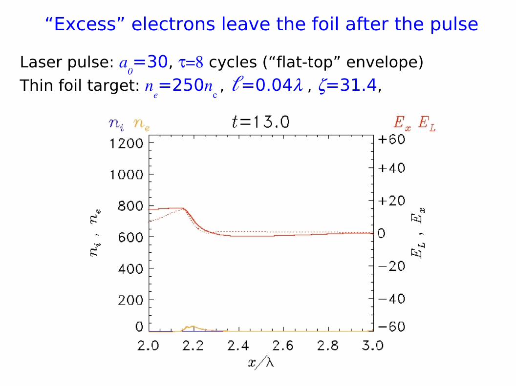
“Excess” electrons leave the foil after the pulse
Laser pulse: a0=30, =8 cycles (“flat-top” envelope)
Thin foil target: ne=250n
c , ℓ=0.04 , =31.4,

“Excess” electrons leave the foil after the pulse
Laser pulse: a0=30, =8 cycles (“flat-top” envelope)
Thin foil target: ne=250n
c , ℓ=0.04 , =31.4,

“Excess” electrons leave the foil after the pulse
Laser pulse: a0=30, =8 cycles (“flat-top” envelope)
Thin foil target: ne=250n
c , ℓ=0.04 , =31.4,

“Excess” electrons leave the foil after the pulse
Laser pulse: a0=30, =8 cycles (“flat-top” envelope)
Thin foil target: ne=250n
c , ℓ=0.04 , =31.4,

“Excess” electrons leave the foil after the pulse
Laser pulse: a0=30, =8 cycles (“flat-top” envelope)
Thin foil target: ne=250n
c , ℓ=0.04 , =31.4,

“Excess” electrons leave the foil after the pulse
Laser pulse: a0=30, =8 cycles (“flat-top” envelope)
Thin foil target: ne=250n
c , ℓ=0.04 , =31.4,

“Excess” electrons leave the foil after the pulse
Laser pulse: a0=30, =8 cycles (“flat-top” envelope)
Thin foil target: ne=250n
c , ℓ=0.04 , =31.4,

“Excess” electrons leave the foil after the pulse
Laser pulse: a0=30, =8 cycles (“flat-top” envelope)
Thin foil target: ne=250n
c , ℓ=0.04 , =31.4,
“Excess” electrons leave the foil after the pulse
Laser pulse: a0=30, =8 cycles (“flat-top” envelope)
Thin foil target: ne=250n
c , ℓ=0.04 , =31.4,

“Excess” electrons leave the foil after the pulse
Laser pulse: a0=30, =8 cycles (“flat-top” envelope)
Thin foil target: ne=250n
c , ℓ=0.04 , =31.4,

“Excess” electrons leave the foil after the pulse
Laser pulse: a0=30, =8 cycles (“flat-top” envelope)
Thin foil target: ne=250n
c , ℓ=0.04 , =31.4,

“Light Sail” RPA is not “front side” acceleration
The effective acceleration of only a thin rear layer implies that the scheme may work in double-layer targets (either manufactured or “natural”- hydrogen impurities on the surface) and might be used for the acceleration of protons
Note: This may explain why the “transition to RPA dominance” was observed in numerical experiments for double layer targets
[T.Esirkepov et al., PRL 96, 105001 (2006)]
Such simulations were performed for linear polarization, showing a “transition to RPA dominance” at I>1023 W/cm2 (“Laser-Piston”) which has not a simple explanation (strongly relativistic effects probably need to be considered)
[T.Esirkepov et al., PRL 92, 175003 (2004)]

Simulation of double layer target
Laser pulse: a0=30, =8 cycles (“flat-top” envelope)
Thin foil target: ne=250n
c , ℓ=0.04 , =31.4, C and H layers

Simulation of double layer target
Laser pulse: a0=30, =8 cycles (“flat-top” envelope)
Thin foil target: ne=250n
c , ℓ=0.04 , =31.4, C and H layers

Simulation of double layer target
Laser pulse: a0=30, =8 cycles (“flat-top” envelope)
Thin foil target: ne=250n
c , ℓ=0.04 , =31.4, C and H layers

Simulation of double layer target
Laser pulse: a0=30, =8 cycles (“flat-top” envelope)
Thin foil target: ne=250n
c , ℓ=0.04 , =31.4, C and H layers

Simulation of double layer target
Laser pulse: a0=30, =8 cycles (“flat-top” envelope)
Thin foil target: ne=250n
c , ℓ=0.04 , =31.4, C and H layers

Simulation of double layer target
Laser pulse: a0=30, =8 cycles (“flat-top” envelope)
Thin foil target: ne=250n
c , ℓ=0.04 , =31.4, C and H layers

Simulation of double layer target
Laser pulse: a0=30, =8 cycles (“flat-top” envelope)
Thin foil target: ne=250n
c , ℓ=0.04 , =31.4, C and H layers

Simulation of double layer target
Laser pulse: a0=30, =8 cycles (“flat-top” envelope)
Thin foil target: ne=250n
c , ℓ=0.04 , =31.4, C and H layers

Simulation of double layer target
Laser pulse: a0=30, =8 cycles (“flat-top” envelope)
Thin foil target: ne=250n
c , ℓ=0.04 , =31.4, C and H layers

Simulation of double layer target
Laser pulse: a0=30, =8 cycles (“flat-top” envelope)
Thin foil target: ne=250n
c , ℓ=0.04 , =31.4, C and H layers
H
C

The effective mass of the foil
We are left with one question:
Why the foil velocity is given by the LS formula where thewhole mass (≡thickness) of the foil must be used BUT only athinner, lower mass “foil” is accelerated?
Energy stored in the electrostatic field E
x :
“Conversion efficiency” into electrostatic energy
es :
For a0= , the depletion width d≈ℓ thus
es≈2 :
most of the stored energy is converted into electrostatic energy

The effective mass of the foil
We are left with one question:
Why the foil velocity is given by the LS formula where thewhole mass (≡thickness) of the foil must be used BUT only athinner, lower mass “foil” is accelerated?
For a0= , the depletion width d≈ℓ thus
es≈2 :
most of the stored energy is converted into electrostatic energy
Stored electrostatic energy ≡ inertial mass
total mass=accelerated ions mass + “electrostatic mass” =
initial mass of the foil
the effective conversion into ion energy < 21+A.Macchi, S.Veghini, F.Pegoraro, arXiv:0905.2068

Conclusions
- Hole boring RPA: - more “robust” - less favorable scaling - preplasma control may improve the energy spectrum - interesting for next-future few-cycle interactions and if suitable “flowing”, moderate-density targets can be used
- Light Sail RPA: - (much) more challenging (ultra-high contrast pulse needed, flat-top profiles important...) - very attractive for energy and efficiency - revisited LS model accounts for most of the numerical observations - in principle suitable for double-layer targets and proton acceleration
This talk may be downloaded fromwww.df.unipi.it/~macchi/talks.html