IO-Link Devices – Commissioning - TURCKpdb2.turck.de/repo/media/_de/Anlagen/d900634.pdfIO-Link...
104
Your Global Automation Partner User Manual IO-Link Devices Commissioning
-
Upload
truonglien -
Category
Documents
-
view
230 -
download
1
Transcript of IO-Link Devices – Commissioning - TURCKpdb2.turck.de/repo/media/_de/Anlagen/d900634.pdfIO-Link...
Your Global Automation Partner
User Manual
IO-Link DevicesCommissioning

2 Hans Turck GmbH & Co. KG | T +49 208 4952-0 | F +49 208 4952-264 | [email protected] | www.turck.com
Contents

3 2018/01
Com
mis
sion
ing
with
IO-L
ink
1 About these instructions 5
1.1 Target groups 51.2 Explanation of symbols 51.3 Other documents 51.4 Feedback about these instructions 5
2 Notes on the system 6
2.1 Device identification 62.2 Manufacturer and service 6
3 For your safety 6
3.1 Intended use 6
4 System description 7
4.1 System features 74.2 System design 84.3 Operating principle 94.4 Functions and operating modes 94.4.1 IO-Link mode 94.4.2 Standard I/O mode (SIO mode) 11
5 Connection 12
5.1 Wiring diagrams 125.1.1 IO-Link master 125.1.2 IO-Link device 12
6 Configuring and commissioning 13
6.1 Setting devices via a PC with a configuration tool 146.1.1 Setting with USB adapter and configuration tool 146.1.2 Setting with IO-Link master and configuration tool 246.2 Configuring devices via the PLC program 346.2.1 Commissioning with BLxx and programmable gateway in CODESYS 2 346.2.2 Commissioning with BLxx and TX500 in CODESYS 3 376.3 Commissioning with TBEN and TX507 in CODESYS 3 406.3.1 Commissioning with BLxx and Siemens PLC in Simatic Manager (V5.5) 526.3.2 Commissioning with TBEN and Siemens PLC in Simatic Manager (V5.5) 556.3.3 Commissioning with BLxx and Siemens PLC in the TIA Portal V13 SP1 606.3.4 Commissioning with TBEN and Siemens PLC in the TIA Portal 64
7 Setting 68
7.1 Setting devices via the PLC program with a function block 687.1.1 Setting with a programmable gateway and CODESYS 3 717.1.2 Setting with a programmable gateway and CODESYS 2 797.1.3 Setting with an S7-1200/1500 Siemens PLC and TIA Portal 887.1.4 Setting with an S7-300/400 Siemens PLC and STEP7 V5.5 93
8 Operation 101
8.1 Combining Turck IO-Link devices 102
Contents

4 Hans Turck GmbH & Co. KG | T +49 208 4952-0 | F +49 208 4952-264 | [email protected] | www.turck.com
5 2018/01
Com
mis
sion
ing
with
IO-L
ink
1 About these instructionsThese operating instructions describe the setup, the functions and use of the system, and help you to commission the Turck IO-Link devices. Read this manual carefully before using the sys-tem. This will prevent the risk of personal injury and damage to property. Keep this manual safe during the service life of the system.
1.1 Target groups
These instructions are written for suitably qualified and trained personnel and must be read and followed by anyone configuring and commissioning the system.
1.2 Explanation of symbols
The following symbols are used in these instructions:
NOTENOTE indicates tips, recommendations and important information. The notes contain information, particular operating steps that facilitate work and possibly help to avoid additional work resulting from incorrect procedures.
➤ MANDATORY ACTIONThis symbol denotes actions that the user must carry out.
➥ RESULT OF ACTIONThis symbol denotes the relevant results of actions and procedures.
1.3 Other documents
Besides this document the following material can be found on the Internet at www.turck.com: ■ Product-specific data sheets ■ Product-specific operating instructions ■ TBEN-S2-4IOL user manual (D301369) ■ TBEN-L…-8IOL user manual (D301407) ■ IO-Link master user manual for BLxx (D301339) ■ User manual for TBPN-L1-FDIO1-2IOL hybrid safety I/O module (D301379) ■ IO-Link parameter manuals ■ Safety manuals ■ Device approvals
1.4 Feedback about these instructions
We make every effort to ensure that these instructions are as informative and as clear as pos-sible. If you have any suggestions for improving the design or if some information is missing in the document, please send your suggestions to [email protected].

6 Hans Turck GmbH & Co. KG | T +49 208 4952-0 | F +49 208 4952-264 | [email protected] | www.turck.com
Notes on the system
2 Notes on the system2.1 Device identification
This manual applies to all IO-Link capable Turck devices.
2.2 Manufacturer and service
Turck supports you in your projects – from the initial analysis right through to the commission-ing of your application. The Turck product database offers you several software tools for pro-gramming, configuring or commissioning, as well as data sheets and CAD files in many export formats. You can access the Product Database directly via the following address: www.turck.de/productsFor further inquiries in Germany contact the Sales and Service Team on:Sales: +49 208 4952-380Technical: +49 208 4952-390Internet: www.turck.com/support
For overseas inquiries contact your national Turck representative.
Hans Turck GmbH & Co. KGWitzlebenstraße 745472 Mülheim an der RuhrGermany
3 For your safetyThe product is designed according to state of the art technology. Residual hazards, however, still exist. Observe the following warnings and safety regulations in order to prevent danger to persons and property. Turck accepts no liability for damage caused by failure to observe these warnings and safety instructions.
3.1 Intended use
IO-Link is a digital point-to-point connection for use in industrial automation applications. The IO-Link interface enables IO-Link sensors and actuators to be set and operated. Cyclical process data and acyclical data as well as energy can be transferred between an IO-Link master and an IO-Link device.
IO-Link enables different devices (e.g. a temperature sensor and a linear position sensor) to be operated on one input module.
For further information refer to
7 2018/01
Com
mis
sion
ing
with
IO-L
ink
4 System descriptionIO-Link is a fieldbus independent communication interface for sensors and actuators. Signals and energy can be exchanged between any networks, fieldbuses and backplane buses via a digital, serial point-to-point connection.
Each IO-Link system consists of an IO-Link master and an IO-Link device (e.g. sensor, I/O hub, valve block). An IO-Link master is provided with at least one IO-Link port (channel). One IO-Link device can be connected to each port. The system components are interconnected according to the port specification via unshielded 3-wire or 5-wire standard cables.
The IO-Link technology is described in the “IO-Link Interface and System Specification” and IEC 61131-9. IO-Link-capable devices comply either with specification V1.0 or specification V1.1.
The properties, functions and parameters of the IO-Link device are represented in an electronic device description (IODD). The IODDs for Turck devices can be downloaded via the Turck Soft-ware Manager and can also be obtained free of charge from www.turck.com. The IODDs of all devices have the same structure and contain the following information for system integration: ■ Communication properties ■ Device parameters with value range and default value ■ Identification, process and diagnostic data ■ Device data ■ Text description ■ Picture of the device ■ Logo of the manufacturer
The structure of the IODD is defined by the IO-Link specification and is the same for all IO-Link devices. The IODD is based on indexes. The communication properties, device parameters, identification, process, diagnostic and device data are assigned to fixed indexes in the IODD, via which the parameters can be controlled. Some indexes are further divided by subindexes.
4.1 System features
■ Point-to-point connection (max. cable length: 20 m) ■ Unshielded 3-wire or 5-wire standard cables ■ Cyclical process data transmission ■ Acyclical data transmission, e.g. device data and events ■ Communication between IO-Link master and IO-Link device possible in 3 baud rates ■ Parallel exchange of device data without influencing the process data ■ Communication via 24 V pulse modulation, standard UART protocol

8 Hans Turck GmbH & Co. KG | T +49 208 4952-0 | F +49 208 4952-264 | [email protected] | www.turck.com
System description
4.2 System design
At least one IO-Link master and one IO-Link device (e.g. sensors or actuators) are required for IO-Link communication. IO-Link master and IO-Link device are interconnected via an unshield-ed 3-wire or 5-wire standard cable. The setting can be carried out with a configuration tool or via the fieldbus level. The IO-Link master establishes the connection between IO-Link device and the higher-level control system. An IO-Link master can have several IO-Link ports. Only one IO-Link device can be connected to each port.IO-Link hubs also make it possible to integrate devices without an IO-Link output in automation systems via IO-Link.Standard tools and functions are provided for the integration, commissioning and configura-tion of the IO-Link communication.
Fig. 1: IO-Link system overview
BL6
7-B
-4M
8
0
2
1
0
3
2
BL6
7-B
-4M
12-P
0
1
2
3
4
5
6
7
0
Power BL6
7-B
-1R
SM
DBL67 DBL67 DBL67
BL6
7-B
-8M
8
DBL67
1
3
DBL67DBL67
1 1 1 1 1
0
2
4
6
3
5
7
0 0
2
0
2
4
6
3
5
7
0
2
3
5
4
7
6
BL6
7-B
-2M
12
0
1
2
3
9 2018/01
Com
mis
sion
ing
with
IO-L
ink
4.3 Operating principle
IO-Link is a digital point-to-point connection between an IO-Link master and an IO-Link device. Process data and other information such as parameters and diagnostic messages are trans-ferred with a 24 V pulse modulation via a combined switching status and data channel (C/Q).
IO-Link communication is independent of the fieldbus used.
4.4 Functions and operating modes
The operating mode can be set separately at any port of the IO-Link master.
Two operating modes are available for the IO-Link master ■ IO-Link mode: IO-Link communication possible ■ Standard I/O mode (SIO): digital I/O communication
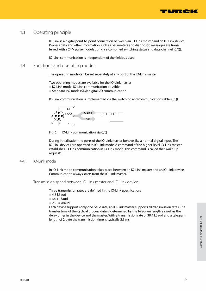
IO-Link communication is implemented via the switching and communication cable (C/Q).
Fig. 2: IO-Link communication via C/Q
During initialization the ports of the IO-Link master behave like a normal digital input. The IO-Link devices are operated in IO-Link mode. A command of the higher-level IO-Link master establishes IO-Link communication in IO-Link mode. This command is called the “Wake-up request”.
4.4.1 IO-Link mode
In IO-Link mode communication takes place between an IO-Link master and an IO-Link device. Communication always starts from the IO-Link master.
Transmission speed between IO-Link master and IO-Link device
Three transmission rates are defined in the IO-Link specification: ■ 4.8 kBaud ■ 38.4 kBaud ■ 230.4 kBaud
Each device supports only one baud rate, an IO-Link master supports all transmission rates. The transfer time of the cyclical process data is determined by the telegram length as well as the delay times in the device and the master. With a transmission rate of 38.4 kBaud and a telegram length of 2 byte the transmission time is typically 2.3 ms.
2
1
3
L+
C/Q
L–
4
5
IO-Link
SIO

10 Hans Turck GmbH & Co. KG | T +49 208 4952-0 | F +49 208 4952-264 | [email protected] | www.turck.com
System description
Response times
The response time of the IO-Link system provides information on the frequency and speed of the data transmission between IO-Link master and IO-Link device. This response time depends on the following factors: ■ Minimum cycle time: Intervals defined in the IODD in which the IO-Link master addresses the IO-Link device. Different minimum cycle times can be defined for different devices.
■ Internal processing time of the IO-Link master and the IO-Link device
Cyclical and acyclical communication
The data exchanged between IO-Link master and the IO-Link device can be divided into cyclical process data and acyclical data. Process data and value states are transferred cyclically. Acyclical data is transferred separately to cyclic process data. Acyclical data includes device data, param-eter functions and events such as diagnostic information, which is only transferred on request. The two communication types are independent of each other and do not interact.
Cyclical communication
Process data Value status (port qualifier)
– 0…32 bytes of process data possible per device (each input and output) – Process data size determined by the device
– The Port Qualifier indicates whether the process data is valid or not
Acylical communication
Device data Events
– Parameters, identification data or diagnostic information – Replacement on request of the IO-Link master – Device data can be written to the device or read from the device
– Device indicates event to master: Error messages and warnings – Master indicates event to device: e.g. cable break or communication abort
Combining IO-Link devices with different specifications
Only devices of specification V1.0 can be operated on IO-Link masters of specification V1.0. Devices of specification V1.0 and V1.1 can be operated on IO-Link masters of specification V1.1.
IO-Link device V1.0 IO-Link device V1.1
IO-Link master V1.0
IO-Link master V1.1

11 2018/01
Com
mis
sion
ing
with
IO-L
ink
Data retention mode
NOTEData retention mode is only available for devices complying with the IO-Link specifica-tion V1.1.
Data retention mode makes it possible to replace IO-Link devices without the need for a reconfiguration. The IO-Link master or the IO-Link device save the device parameters set in the previous con-figuration. In data retention mode the parameter data memories of IO-Link master and IO-Link device are synchronized.If data retention mode is activated in the IO-Link master, the master writes the stored device pa-rameters to the new device after a device is replaced. The application can be restarted without having to perform a new configuration.
Fig. 3: Data retention mode (example)
4.4.2 Standard I/O mode (SIO mode)
In standard I/O mode IO-Link devices behave like digital sensors or actuators. In this mode the devices only send input or output data to the higher-level instance. IO-Link access to the device is not possible.
IO-Link-Master(IOLM)
IO-Link-Device(IOLD)
DS_UPLOAD_FLAG

12 Hans Turck GmbH & Co. KG | T +49 208 4952-0 | F +49 208 4952-264 | [email protected] | www.turck.com
Connection
5 ConnectionA Turck IO-Link master is provided with one or several ports for connecting IO-Link devices. The IO-Link devices are connected via unshielded 3-wire or 5-wire standard cables to the ports of the IO-Link master. The maximum cable length is 20 m.
The IO-Link specification for IO-Link masters defines two different types of ports with different power supplies. ■ Port class A: The functions of pins 2 and 5 are manufacturer specific. For example, pin 2 can be assigned with an additional digital channel.
■ Port class B: An additional electrically isolated power supply is provided via pins 2 and 5. Class B IO-Link ports are suitable for connecting IO-Link devices with a greater power requirement. A 5-wire standard cable is required to use the additional power supply.
Adapters (ident no. 6629515 and 6629516) are available for connecting Port class B devices to Port class A masters.
5.1 Wiring diagrams
5.1.1 IO-Link master
Pin Pin assignment Wiring diagram
Pin 1 V1+
4
1 3
2
5
Pin 2 manufacturer specific (e.g. additional digital channel)
Pin 3 V1-
Pin 4 C/Q
Pin 5 n. c.
Fig. 4: Wiring diagram of IO-Link master Port class A
Pin Pin assignment Wiring diagram
Pin 1 V1+
4
1 3
2
5
Pin 2 V2+
Pin 3 V1-
Pin 4 C/Q
Pin 5 V2-
Fig. 5: Wiring diagram of IO-Link master Port class B
5.1.2 IO-Link device
Pin Pin assignment Wiring diagram
Pin 1 V1+
3
2
4
1
5
Pin 2 not specified
Pin 3 V1-
Pin 4 C/Q
Pin 5 n. c.
Fig. 6: Wiring diagram of IO-Link device Port class A
13 2018/01
Com
mis
sion
ing
with
IO-L
ink
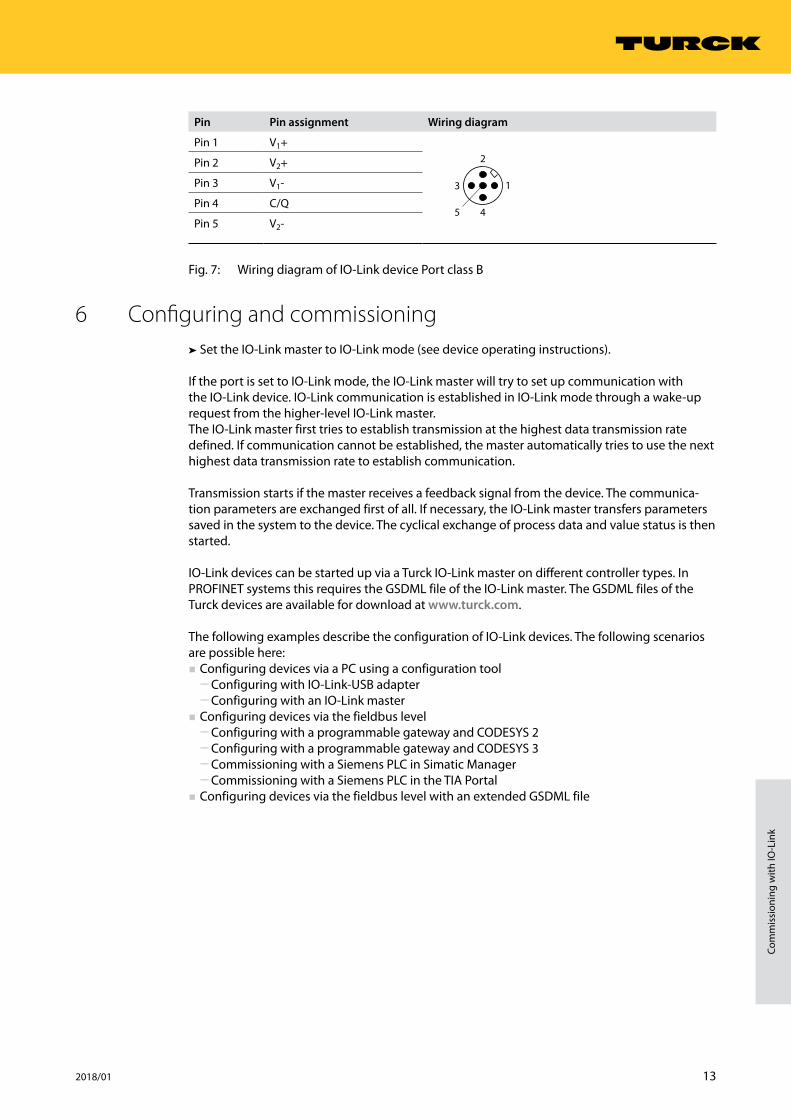
Pin Pin assignment Wiring diagram
Pin 1 V1+
3
2
4
1
5
Pin 2 V2+
Pin 3 V1-
Pin 4 C/Q
Pin 5 V2-
Fig. 7: Wiring diagram of IO-Link device Port class B
6 Configuring and commissioning➤➤ Set the IO-Link master to IO-Link mode (see device operating instructions).
If the port is set to IO-Link mode, the IO-Link master will try to set up communication with the IO-Link device. IO-Link communication is established in IO-Link mode through a wake-up request from the higher-level IO-Link master. The IO-Link master first tries to establish transmission at the highest data transmission rate defined. If communication cannot be established, the master automatically tries to use the next highest data transmission rate to establish communication.
Transmission starts if the master receives a feedback signal from the device. The communica-tion parameters are exchanged first of all. If necessary, the IO-Link master transfers parameters saved in the system to the device. The cyclical exchange of process data and value status is then started.
IO-Link devices can be started up via a Turck IO-Link master on different controller types. In PROFINET systems this requires the GSDML file of the IO-Link master. The GSDML files of the Turck devices are available for download at www.turck.com.
The following examples describe the configuration of IO-Link devices. The following scenarios are possible here: ■ Configuring devices via a PC using a configuration tool
ū Configuring with IO-Link-USB adapter ū Configuring with an IO-Link master
■ Configuring devices via the fieldbus level ū Configuring with a programmable gateway and CODESYS 2 ū Configuring with a programmable gateway and CODESYS 3 ū Commissioning with a Siemens PLC in Simatic Manager ū Commissioning with a Siemens PLC in the TIA Portal
■ Configuring devices via the fieldbus level with an extended GSDML file
14 Hans Turck GmbH & Co. KG | T +49 208 4952-0 | F +49 208 4952-264 | [email protected] | www.turck.com
Configuring and commissioning
6.1 Setting devices via a PC with a configuration tool
IO-Link devices can be set via a PC with a configuration tool (e.g. PACTware™).
All the required Turck software components can be downloaded via the Turck Software Man-ager. The Turck Software Manager is available free of charge from www.turck.com.
6.1.1 Setting with USB adapter and configuration tool
Software used
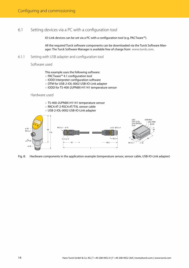
This example uses the following software: ■ PACTware™ 4.1 configuration tool ■ IODD Interpreter configuration software ■ DTM for USB-2-IOL-0002 USB-IO-Link adapter ■ IODD for TS-400-2UPN8X-H1141 temperature sensor
Hardware used
■ TS-400-2UPN8X-H1141 temperature sensor ■ RKC4.4T-2-RSC4.4T/TXL sensor cable ■ USB-2-IOL-0002 USB-IO-Link adapter
���
�������������
���
����
42
11.5
ø 15M12 x 1
L
M12 x 1ø 15
49.5
18.2 41
24
54
M12 x 1 16
USB-Mini
IN-DC
LED:CH1 (C/Q)CH2 (DI/DO)Error
LED: PWR
Fig. 8: Hardware components in the application example (temperature sensor, sensor cable, USB-IO-Link adapter)
15 2018/01
Com
mis
sion
ing
with
IO-L
ink
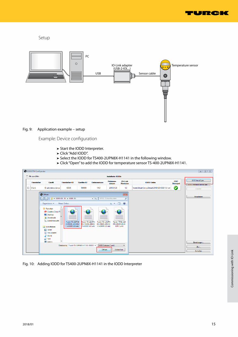
Setup
Fig. 9: Application example – setup
Example: Device configuration
➤➤ Start the IODD Interpreter.➤➤ Click “Add IODD”.➤➤ Select the IODD for TS400-2UPN8X-H1141 in the following window.➤➤ Click “Open” to add the IODD for temperature sensor TS-400-2UPN8X-H1141.
Fig. 10: Adding IODD for TS400-2UPN8X-H1141 in the IODD Interpreter
USB
PC
Sensor cable
IO-Link adapter(USB-2-IOL...)
Temperature sensor
16 Hans Turck GmbH & Co. KG | T +49 208 4952-0 | F +49 208 4952-264 | [email protected] | www.turck.com
Configuring and commissioning
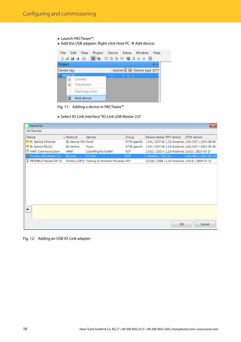
➤➤ Launch PACTware™.➤➤ Add the USB adapter: Right-click Host PC Add device.
Fig. 11: Adding a device in PACTware™
➤➤ Select IO-Link interface “IO-Link USB Master 2.0”.
Fig. 12: Adding an USB-IO-Link adapter

17 2018/01
Com
mis
sion
ing
with
IO-L
ink
➤➤ Start the topology scan in order to find devices connected to the IO-Link adapter: Right-click the IO-Link adapter Click the topology scan.
Fig. 13: Starting the topology scan
18 Hans Turck GmbH & Co. KG | T +49 208 4952-0 | F +49 208 4952-264 | [email protected] | www.turck.com
Configuring and commissioning
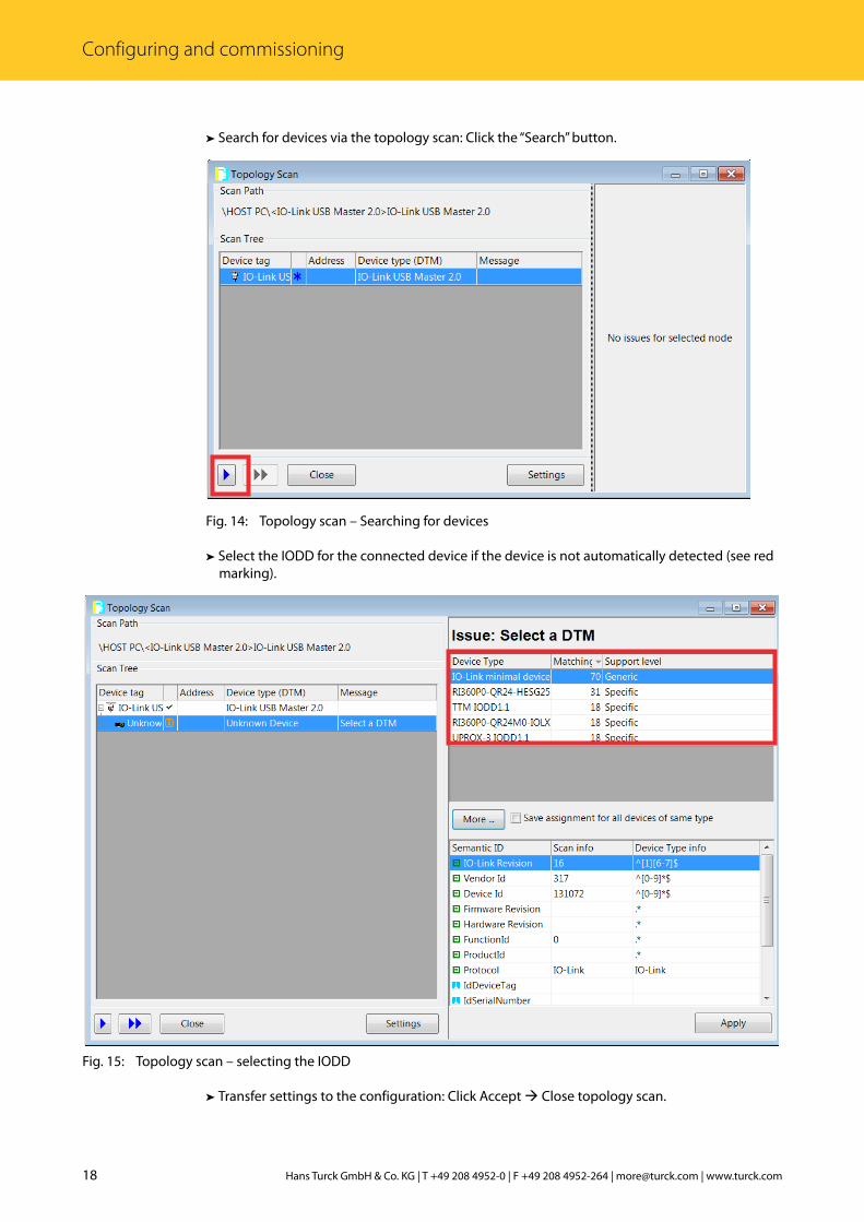
➤➤ Search for devices via the topology scan: Click the “Search” button.
Fig. 14: Topology scan – Searching for devices
➤➤ Select the IODD for the connected device if the device is not automatically detected (see red marking).
Fig. 15: Topology scan – selecting the IODD
➤➤ Transfer settings to the configuration: Click Accept Close topology scan.
19 2018/01
Com
mis
sion
ing
with
IO-L
ink
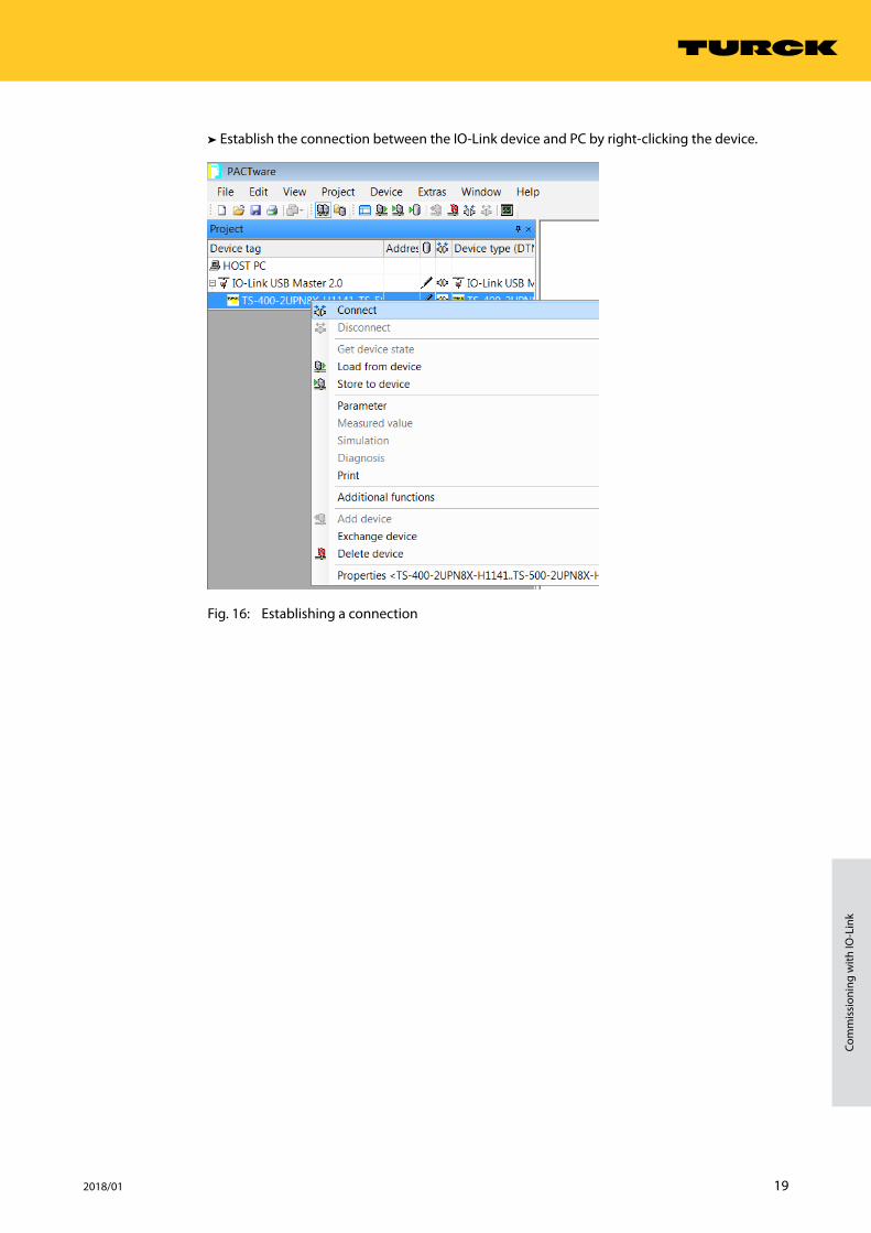
➤➤ Establish the connection between the IO-Link device and PC by right-clicking the device.
Fig. 16: Establishing a connection

20 Hans Turck GmbH & Co. KG | T +49 208 4952-0 | F +49 208 4952-264 | [email protected] | www.turck.com
Configuring and commissioning
➤➤ Start Expert mode by right-clicking the adapter.
Fig. 17: Starting Expert mode
21 2018/01
Com
mis
sion
ing
with
IO-L
ink
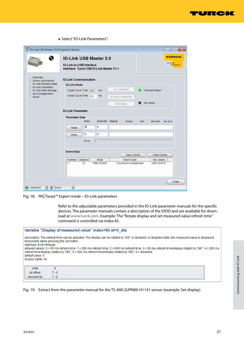
➤➤ Select “IO-Link Parameters”.
Fig. 18: PACTware™ Expert mode – IO-Link parameters
Refer to the adjustable parameters provided in the IO-Link parameter manuals for the specific devices. The parameter manuals contain a description of the IODD and are available for down-load at www.turck.com. Example: The “Rotate display and set measured value refresh time” command is controlled via index 85.
Fig. 19: Extract from the parameter manual for the TS-400-2UPN8X-H1141 sensor (example: Set display)
22 Hans Turck GmbH & Co. KG | T +49 208 4952-0 | F +49 208 4952-264 | [email protected] | www.turck.com
Configuring and commissioning
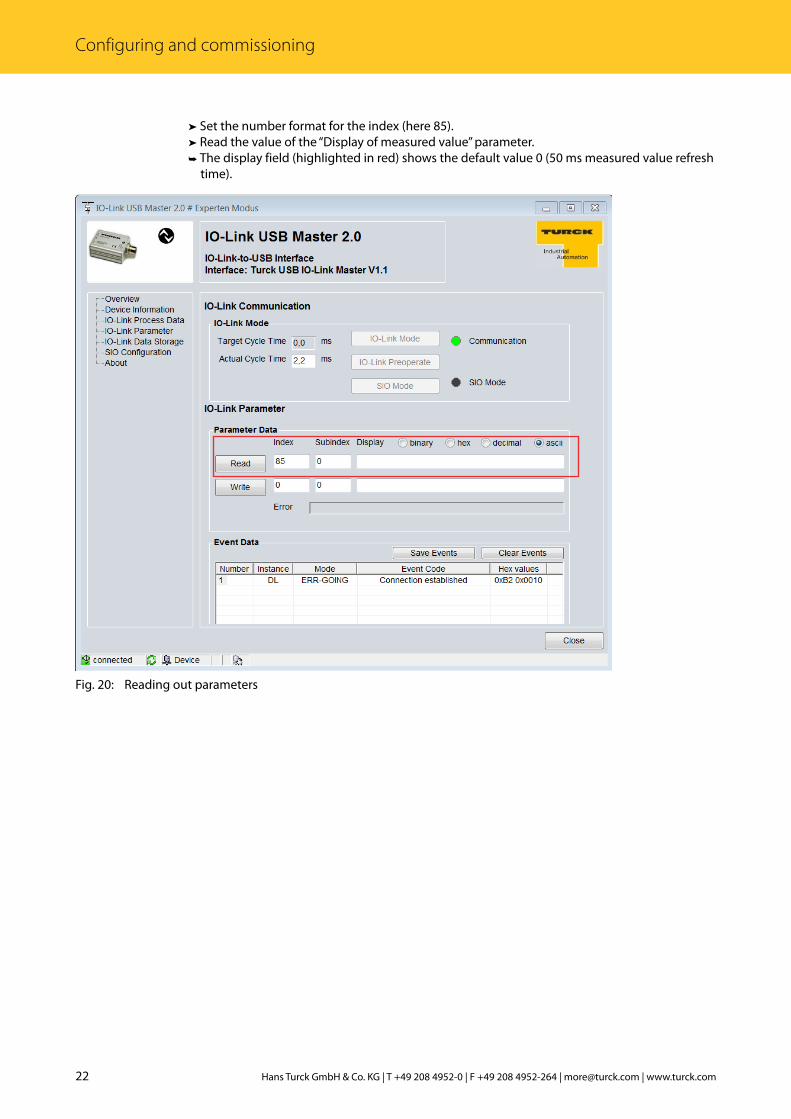
➤➤ Set the number format for the index (here 85).➤➤ Read the value of the “Display of measured value” parameter.➤➥ The display field (highlighted in red) shows the default value 0 (50 ms measured value refresh time).
Fig. 20: Reading out parameters
23 2018/01
Com
mis
sion
ing
with
IO-L
ink
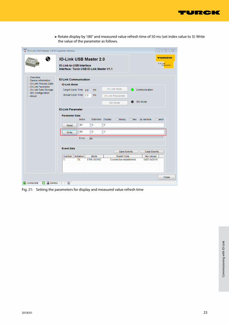
➤➤ Rotate display by 180° and measured value refresh time of 50 ms (set index value to 3): Write the value of the parameter as follows.
Fig. 21: Setting the parameters for display and measured value refresh time
24 Hans Turck GmbH & Co. KG | T +49 208 4952-0 | F +49 208 4952-264 | [email protected] | www.turck.com
Configuring and commissioning
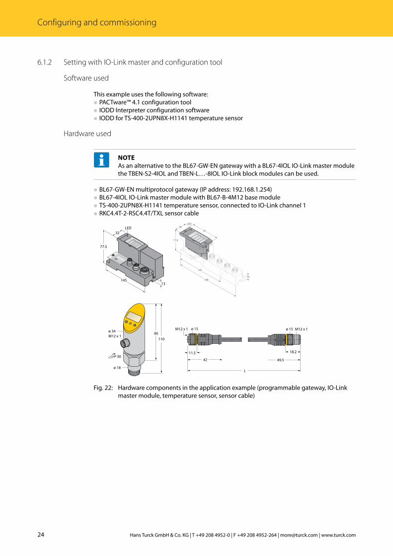
6.1.2 Setting with IO-Link master and configuration tool
Software used
This example uses the following software: ■ PACTware™ 4.1 configuration tool ■ IODD Interpreter configuration software ■ IODD for TS-400-2UPN8X-H1141 temperature sensor
Hardware used
NOTEAs an alternative to the BL67-GW-EN gateway with a BL67-4IOL IO-Link master module the TBEN-S2-4IOL and TBEN-L…-8IOL IO-Link block modules can be used.
■ BL67-GW-EN multiprotocol gateway (IP address: 192.168.1.254) ■ BL67-4IOL IO-Link master module with BL67-B-4M12 base module ■ TS-400-2UPN8X-H1141 temperature sensor, connected to IO-Link channel 1 ■ RKC4.4T-2-RSC4.4T/TXL sensor cable
LED
77.5
145
32
13
���
��
��
����
�����
���
���
�������������
���
����
42
11.5
ø 15M12 x 1
L
M12 x 1ø 15
49.5
18.2
Fig. 22: Hardware components in the application example (programmable gateway, IO-Link master module, temperature sensor, sensor cable)

25 2018/01
Com
mis
sion
ing
with
IO-L
ink
Setup
Fig. 23: Application example – setup
Example: Device configuration
➤➤ Start the IODD Interpreter.➤➤ Click “Add IODD”.➤➤ Select the IODD for TS400-2UPN8X-H1141 in the following window.➤➤ Click “Open” to add the IODD for temperature sensor TS-400-2UPN8X-H1141.
Fig. 24: Adding IODD for TS400-2UPN8X-H1141 in the IODD Interpreter
BL6
7-B
-4M
12-P
0
1
2
3
4
5
6
7
DBL67DBL67
1
0
2
4
6
3
5
7
Ethernet- orservice cable
PC
Sensor cable
BL67/IOL-Master
Temperature sensor

26 Hans Turck GmbH & Co. KG | T +49 208 4952-0 | F +49 208 4952-264 | [email protected] | www.turck.com
Configuring and commissioning
➤➤ Launch PACTware™.➤➤ Add IODD in PACTware™ (View Device Catalog Refresh Device Catalog).➤➤ Add Ethernet interface (right-click Host PC Add device).
Fig. 25: Adding a device in PACTware™
➤➤ Select “BL Service Ethernet” interface.
Fig. 26: Adding BL Service Ethernet
27 2018/01
Com
mis
sion
ing
with
IO-L
ink
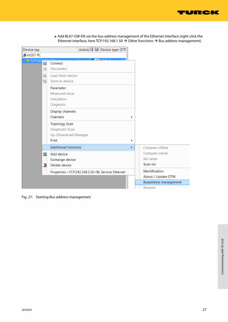
➤➤ Add BL67-GW-EN via the bus address management of the Ethernet interface (right-click the Ethernet interface, here TCP:192.168.1.50 Other functions Bus address management).
Fig. 27: Starting Bus address management
28 Hans Turck GmbH & Co. KG | T +49 208 4952-0 | F +49 208 4952-264 | [email protected] | www.turck.com
Configuring and commissioning
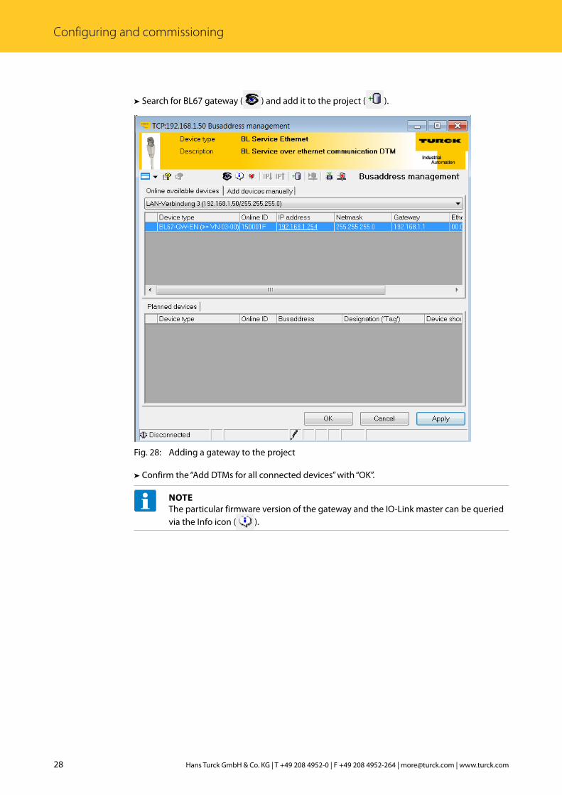
➤➤ Search for BL67 gateway ( ) and add it to the project ( ).
Fig. 28: Adding a gateway to the project
➤➤ Confirm the “Add DTMs for all connected devices” with “OK”.
NOTEThe particular firmware version of the gateway and the IO-Link master can be queried via the Info icon ( ).

29 2018/01
Com
mis
sion
ing
with
IO-L
ink
➤➤ Start the topology scan in order to find devices connected to the IO-Link master.
Fig. 29: Starting the topology scan

30 Hans Turck GmbH & Co. KG | T +49 208 4952-0 | F +49 208 4952-264 | [email protected] | www.turck.com
Configuring and commissioning
➤➤ If a DTM is found during a topology scan instead of an IODD, load the IODD manually.
Fig. 30: Replacing DTM with IODD
31 2018/01
Com
mis
sion
ing
with
IO-L
ink
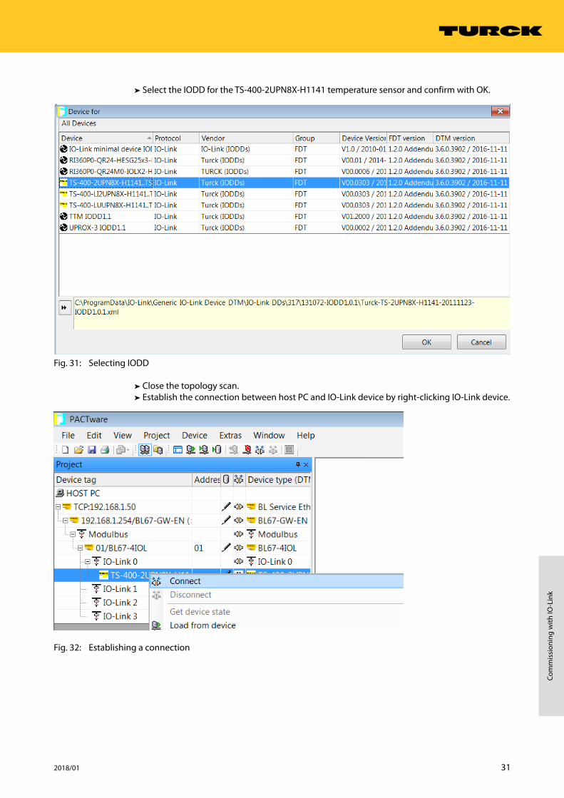
➤➤ Select the IODD for the TS-400-2UPN8X-H1141 temperature sensor and confirm with OK.
Fig. 31: Selecting IODD
➤➤ Close the topology scan.➤➤ Establish the connection between host PC and IO-Link device by right-clicking IO-Link device.
Fig. 32: Establishing a connection

32 Hans Turck GmbH & Co. KG | T +49 208 4952-0 | F +49 208 4952-264 | [email protected] | www.turck.com
Configuring and commissioning
➤➤ In the tree structure double-click the IO-Link device in order to display the parameters.
Fig. 33: IO-Link parameters

33 2018/01
Com
mis
sion
ing
with
IO-L
ink
➤➤ Set the Measured value display parameter to “50 ms refresh time, 180° rotated”.
Fig. 34: Setting the measured value display
➤➤ Write parameters to the device.
Fig. 35: Writing parameters to the device
34 Hans Turck GmbH & Co. KG | T +49 208 4952-0 | F +49 208 4952-264 | [email protected] | www.turck.com
Configuring and commissioning
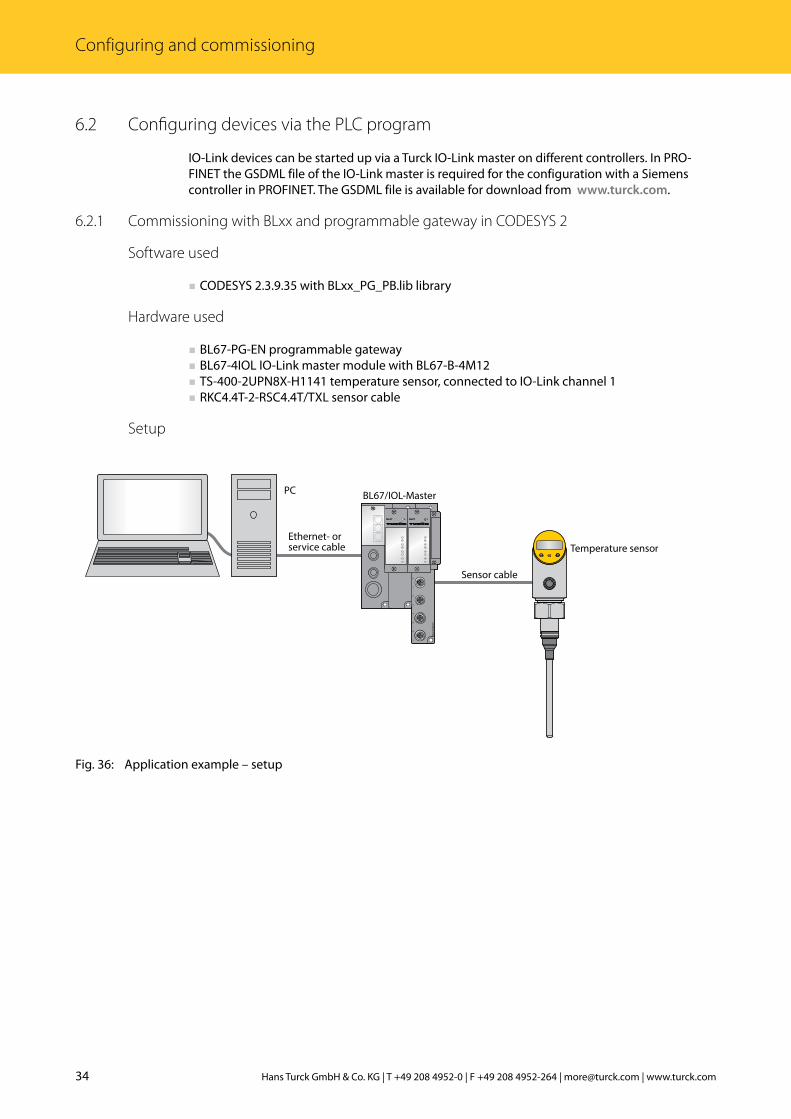
6.2 Configuring devices via the PLC program
IO-Link devices can be started up via a Turck IO-Link master on different controllers. In PRO-FINET the GSDML file of the IO-Link master is required for the configuration with a Siemens controller in PROFINET. The GSDML file is available for download from www.turck.com.
6.2.1 Commissioning with BLxx and programmable gateway in CODESYS 2
Software used
■ CODESYS 2.3.9.35 with BLxx_PG_PB.lib library
Hardware used
■ BL67-PG-EN programmable gateway ■ BL67-4IOL IO-Link master module with BL67-B-4M12 ■ TS-400-2UPN8X-H1141 temperature sensor, connected to IO-Link channel 1 ■ RKC4.4T-2-RSC4.4T/TXL sensor cable
Setup
Fig. 36: Application example – setup
BL6
7-B
-4M
12-P
0
1
2
3
4
5
6
7
DBL67DBL67
1
0
2
4
6
3
5
7
Ethernet- orservice cable
PC
Sensor cable
BL67/IOL-Master
Temperature sensor

35 2018/01
Com
mis
sion
ing
with
IO-L
ink
Example: Generic device configuration
NOTEThe BLxx-4IOL IO-Link master can only be configured generically. The connected de-vices must be configured separately.
➤➤ Configure hardware in CODESYS.
Fig. 37: Configuring hardware in CODESYS
36 Hans Turck GmbH & Co. KG | T +49 208 4952-0 | F +49 208 4952-264 | [email protected] | www.turck.com
Configuring and commissioning
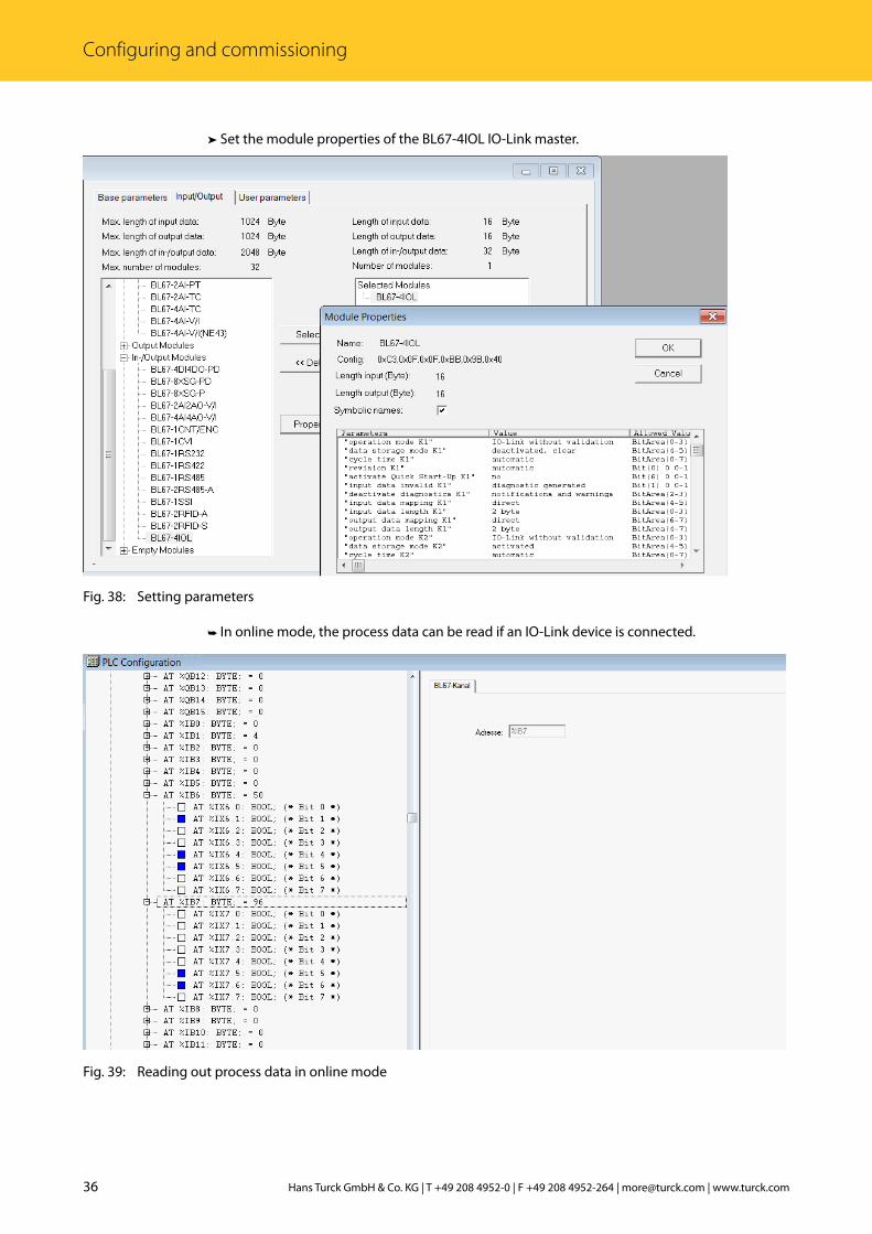
➤➤ Set the module properties of the BL67-4IOL IO-Link master.
Fig. 38: Setting parameters
➤➥ In online mode, the process data can be read if an IO-Link device is connected.
Fig. 39: Reading out process data in online mode

37 2018/01
Com
mis
sion
ing
with
IO-L
ink
6.2.2 Commissioning with BLxx and TX500 in CODESYS 3
Software used
■ CODESYS 3.5 SP8 Patch 1 ■ GSDML file for BL67-GW-EN
Hardware used
■ BL67-GW-EN multiprotocol gateway ■ BL67-4IOL IO-Link master module with BL67-B-4M12 base module ■ TS-400-2UPN8X-H1141 temperature sensor, connected to IO-Link channel 1 ■ RKC4.4T-2-RSC4.4T/TXL sensor cable ■ TX507 visual HMI/PLC device
Setup
Fig. 40: Application example – setup
BL6
7-B
-4M
12-P
0
1
2
3
4
5
6
7
DBL67DBL67
1
0
2
4
6
3
5
7
TX500
Sensor cable
BL67/IOL-Master
Temperature sensorEthernet cable

38 Hans Turck GmbH & Co. KG | T +49 208 4952-0 | F +49 208 4952-264 | [email protected] | www.turck.com
Configuring and commissioning
Example: Configuring the device
NOTEThe BLxx-4IOL IO-Link master can only be configured generically. The connected de-vices must be configured separately.
➤➤ Configure hardware in CODESYS.
Fig. 41: Configuring hardware in CODESYS
39 2018/01
Com
mis
sion
ing
with
IO-L
ink
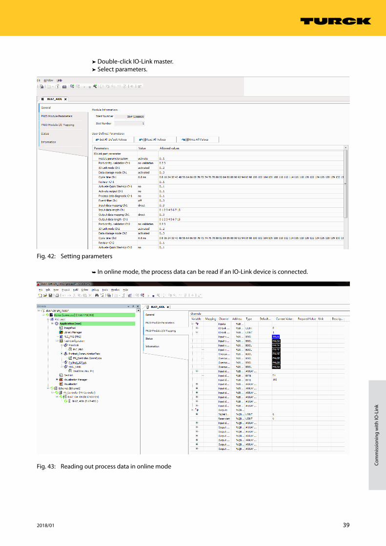
➤➤ Double-click IO-Link master.➤➤ Select parameters.
Fig. 42: Setting parameters
➤➥ In online mode, the process data can be read if an IO-Link device is connected.
Fig. 43: Reading out process data in online mode

40 Hans Turck GmbH & Co. KG | T +49 208 4952-0 | F +49 208 4952-264 | [email protected] | www.turck.com
Configuring and commissioning
6.3 Commissioning with TBEN and TX507 in CODESYS 3
Software used
■ CODESYS 3.5 SP8 Patch 1 ■ GSDM file for TBEN-S2-4IOL
Hardware used
NOTEAs an alternative to the TBEN-S2-4IOL IO-Link block module, the TBEN-L…-8IOL IO-Link block modules can be used.
■ TBEN-S2-4IOL IO-Link master ■ TS-400-2UPN8X-H1141 temperature sensor, connected to IO-Link channel 1 ■ RKC4.4T-2-RSC4.4T/TXL sensor cable ■ TX507 visual HMI/PLC device
Example: Generic device configuration
➤➤ Configure hardware in CODESYS.
Fig. 44: Hardware configuration
41 2018/01
Com
mis
sion
ing
with
IO-L
ink
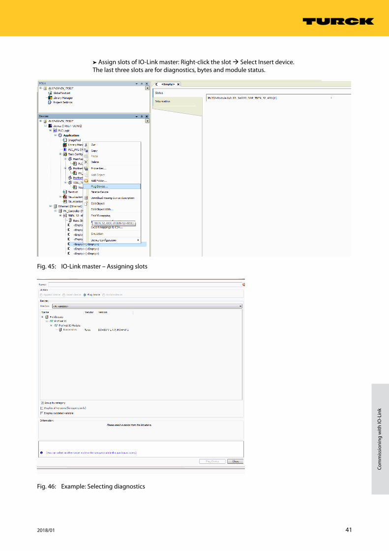
➤➤ Assign slots of IO-Link master: Right-click the slot Select Insert device.The last three slots are for diagnostics, bytes and module status.
Fig. 45: IO-Link master – Assigning slots
Fig. 46: Example: Selecting diagnostics
42 Hans Turck GmbH & Co. KG | T +49 208 4952-0 | F +49 208 4952-264 | [email protected] | www.turck.com
Configuring and commissioning
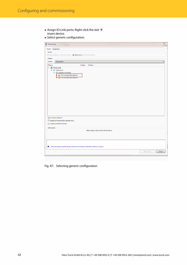
➤➤ Assign IO-Link ports: Right-click the slot Insert device.
➤➤ Select generic configuration.
Fig. 47: Selecting generic configuration

43 2018/01
Com
mis
sion
ing
with
IO-L
ink
➤➤ Configure port.
Fig. 48: Configuring port

44 Hans Turck GmbH & Co. KG | T +49 208 4952-0 | F +49 208 4952-264 | [email protected] | www.turck.com
Configuring and commissioning
➤➥ Online mode enables the process values to be observed.
Fig. 49: Online mode – Observing process values

45 2018/01
Com
mis
sion
ing
with
IO-L
ink
Example: Specific device configuration
NOTEThe TBEN-S2-4IOL IO-Link master can be configured specifically. The connected devices can be configured via the configura-tion program of the PLC.
➤➤ Configure hardware in CODESYS.
Fig. 50: Hardware configuration
46 Hans Turck GmbH & Co. KG | T +49 208 4952-0 | F +49 208 4952-264 | [email protected] | www.turck.com
Configuring and commissioning
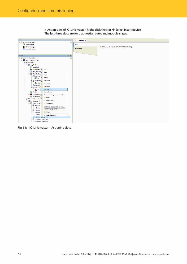
➤➤ Assign slots of IO-Link master: Right-click the slot Select Insert device.The last three slots are for diagnostics, bytes and module status.
Fig. 51: IO-Link master – Assigning slots

47 2018/01
Com
mis
sion
ing
with
IO-L
ink
Fig. 52: Example: Selecting diagnostics
48 Hans Turck GmbH & Co. KG | T +49 208 4952-0 | F +49 208 4952-264 | [email protected] | www.turck.com
Configuring and commissioning
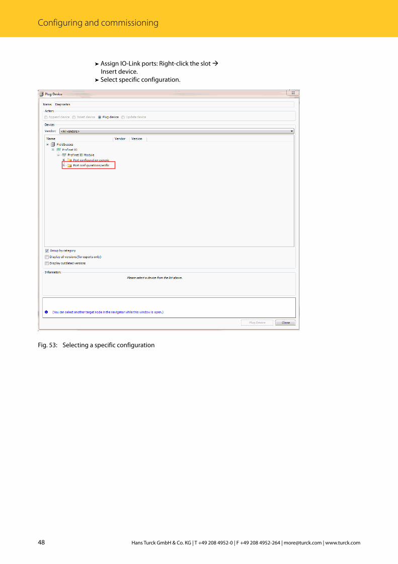
➤➤ Assign IO-Link ports: Right-click the slot Insert device.
➤➤ Select specific configuration.
Fig. 53: Selecting a specific configuration

49 2018/01
Com
mis
sion
ing
with
IO-L
ink
➤➤ Select IO-Link device.
Fig. 54: Selecting the IO-Link device
50 Hans Turck GmbH & Co. KG | T +49 208 4952-0 | F +49 208 4952-264 | [email protected] | www.turck.com
Configuring and commissioning
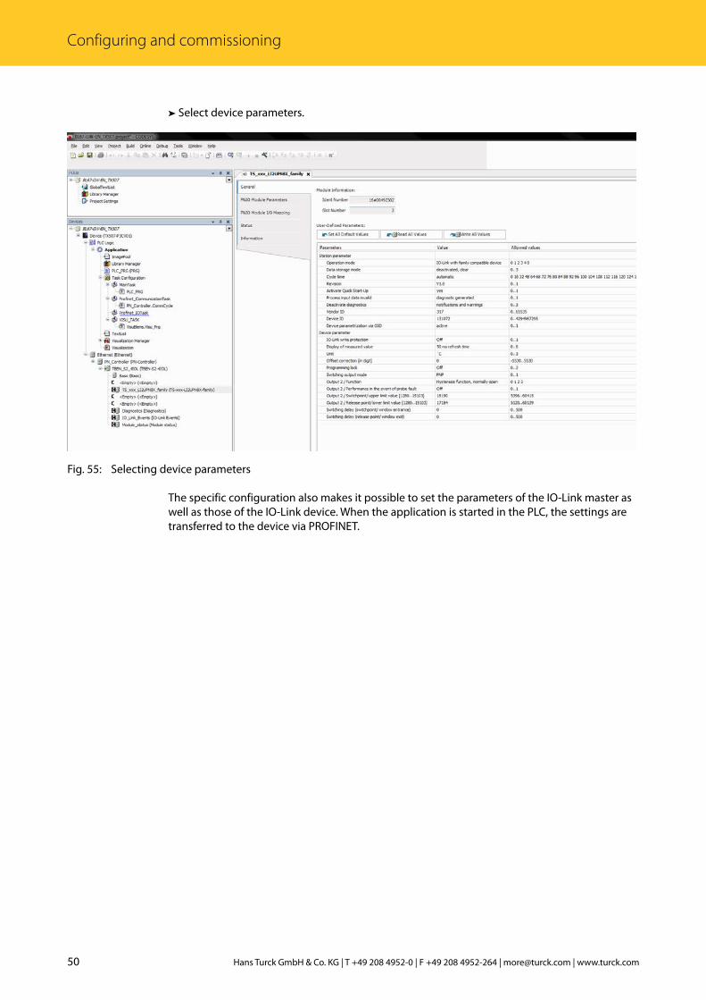
➤➤ Select device parameters.
Fig. 55: Selecting device parameters
The specific configuration also makes it possible to set the parameters of the IO-Link master as well as those of the IO-Link device. When the application is started in the PLC, the settings are transferred to the device via PROFINET.

51 2018/01
Com
mis
sion
ing
with
IO-L
ink
➤➥ Online mode enables the process values to be observed.
Fig. 56: Online mode – Observing process values
52 Hans Turck GmbH & Co. KG | T +49 208 4952-0 | F +49 208 4952-264 | [email protected] | www.turck.com
Configuring and commissioning
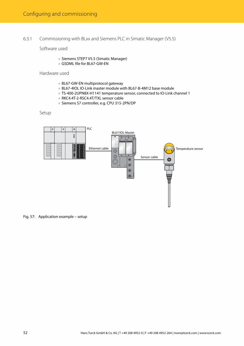
6.3.1 Commissioning with BLxx and Siemens PLC in Simatic Manager (V5.5)
Software used
■ Siemens STEP7 V5.5 (Simatic Manager) ■ GSDML file for BL67-GW-EN
Hardware used
■ BL67-GW-EN multiprotocol gateway ■ BL67-4IOL IO-Link master module with BL67-B-4M12 base module ■ TS-400-2UPN8X-H1141 temperature sensor, connected to IO-Link channel 1 ■ RKC4.4T-2-RSC4.4T/TXL sensor cable ■ Siemens S7 controller, e.g. CPU 315-2PN/DP
Setup
Fig. 57: Application example – setup
BL6
7-B
-4M
12-P
0
1
2
3
4
5
6
7
DBL67DBL67
1
0
2
4
6
3
5
7
Ethernet cable
PLC
Sensor cable
BL67/IOL-Master
Temperature sensor

53 2018/01
Com
mis
sion
ing
with
IO-L
ink
Example: Generic device configuration
NOTEThe BLxx-4IOL IO-Link master can only be configured generically. The connected de-vices must be configured separately.
➤➤ Configure the hardware in Simatic Manager.➤➤ Write the I/O addresses.
Fig. 58: Writing the I/O addresses in Simatic Manager

54 Hans Turck GmbH & Co. KG | T +49 208 4952-0 | F +49 208 4952-264 | [email protected] | www.turck.com
Configuring and commissioning
➤➤ Double-click IO-Link master.➤➤ Select parameters.
Fig. 59: Setting parameters
➤➥ In online mode, the process data can be read if an IO-Link device is connected.
Fig. 60: Reading out process data in online mode
55 2018/01
Com
mis
sion
ing
with
IO-L
ink
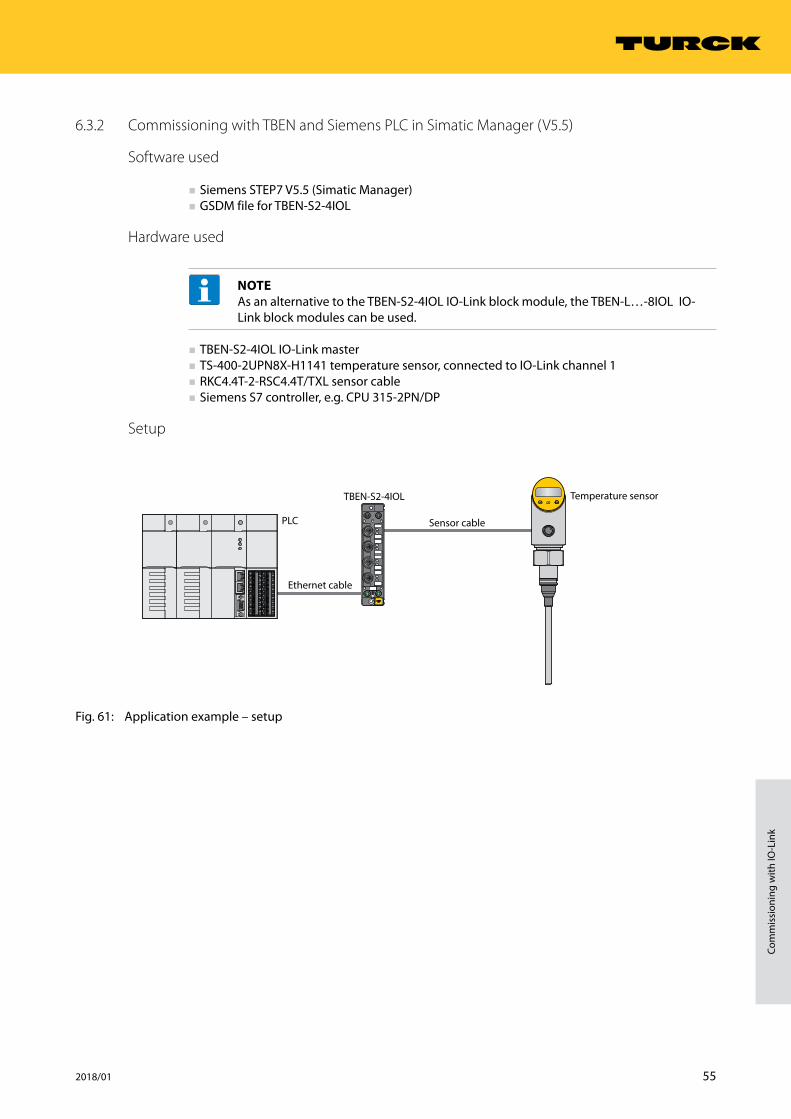
6.3.2 Commissioning with TBEN and Siemens PLC in Simatic Manager (V5.5)
Software used
■ Siemens STEP7 V5.5 (Simatic Manager) ■ GSDM file for TBEN-S2-4IOL
Hardware used
NOTEAs an alternative to the TBEN-S2-4IOL IO-Link block module, the TBEN-L…-8IOL IO-Link block modules can be used.
■ TBEN-S2-4IOL IO-Link master ■ TS-400-2UPN8X-H1141 temperature sensor, connected to IO-Link channel 1 ■ RKC4.4T-2-RSC4.4T/TXL sensor cable ■ Siemens S7 controller, e.g. CPU 315-2PN/DP
Setup
Fig. 61: Application example – setup
Ethernet cable
PLC Sensor cable
TBEN-S2-4IOL Temperature sensor

56 Hans Turck GmbH & Co. KG | T +49 208 4952-0 | F +49 208 4952-264 | [email protected] | www.turck.com
Configuring and commissioning
Example: Specific device configuration
NOTEThe TBEN-S2-4IOL IO-Link master can be configured specifically or generically. The connected Turck devices can be configured via the PLC program.
➤➤ Configure the hardware in Simatic Manager.➤➤ Assign the device ports of the TBEN IO-Link master.
Fig. 62: Assigning device ports
57 2018/01
Com
mis
sion
ing
with
IO-L
ink
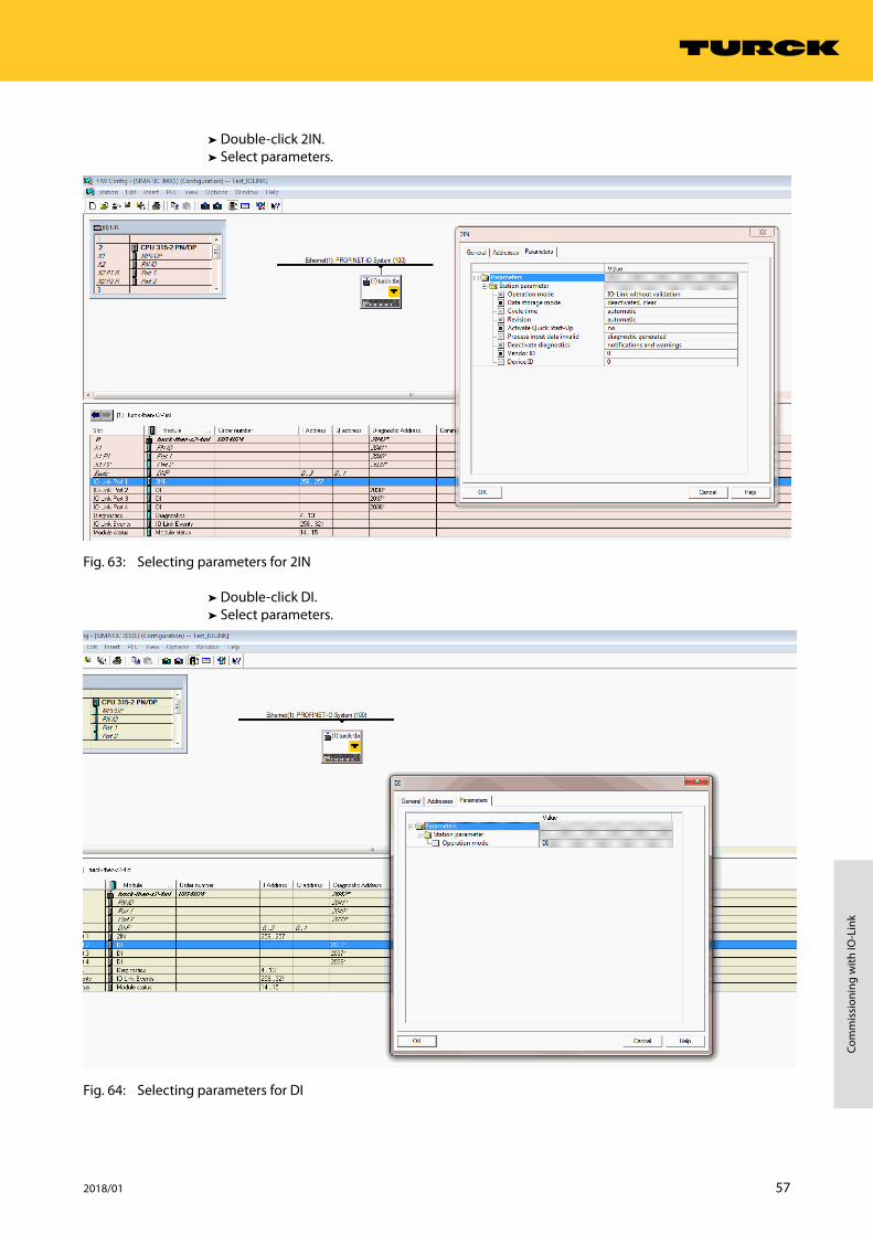
➤➤ Double-click 2IN.➤➤ Select parameters.
Fig. 63: Selecting parameters for 2IN
➤➤ Double-click DI.➤➤ Select parameters.
Fig. 64: Selecting parameters for DI
58 Hans Turck GmbH & Co. KG | T +49 208 4952-0 | F +49 208 4952-264 | [email protected] | www.turck.com
Configuring and commissioning
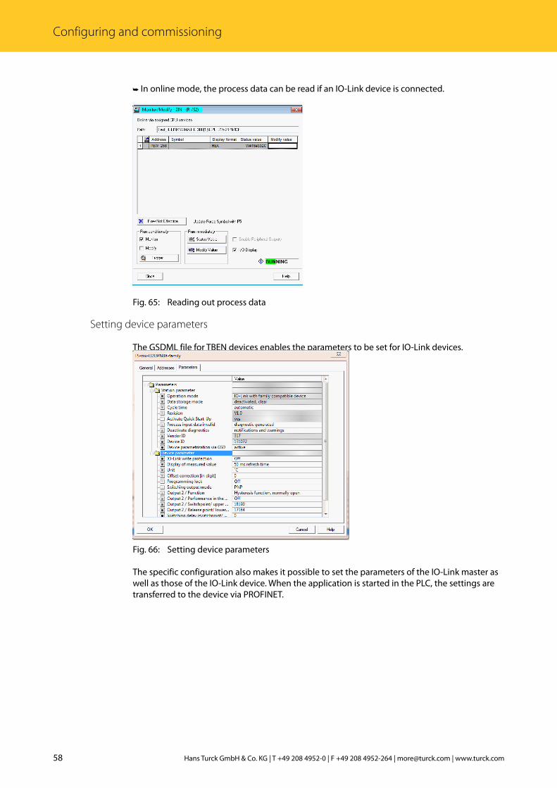
➤➥ In online mode, the process data can be read if an IO-Link device is connected.
Fig. 65: Reading out process data
Setting device parameters
The GSDML file for TBEN devices enables the parameters to be set for IO-Link devices.
Fig. 66: Setting device parameters
The specific configuration also makes it possible to set the parameters of the IO-Link master as well as those of the IO-Link device. When the application is started in the PLC, the settings are transferred to the device via PROFINET.

59 2018/01
Com
mis
sion
ing
with
IO-L
ink
➤➥ Online mode enables the process data of the connected device to be read.
Fig. 67: Reading out process data
60 Hans Turck GmbH & Co. KG | T +49 208 4952-0 | F +49 208 4952-264 | [email protected] | www.turck.com
Configuring and commissioning
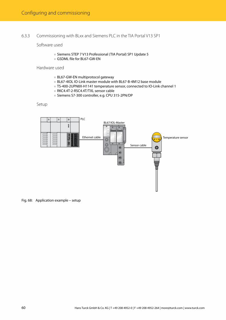
6.3.3 Commissioning with BLxx and Siemens PLC in the TIA Portal V13 SP1
Software used
■ Siemens STEP 7 V13 Professional (TIA Portal) SP1 Update 5 ■ GSDML file for BL67-GW-EN
Hardware used
■ BL67-GW-EN multiprotocol gateway ■ BL67-4IOL IO-Link master module with BL67-B-4M12 base module ■ TS-400-2UPN8X-H1141 temperature sensor, connected to IO-Link channel 1 ■ RKC4.4T-2-RSC4.4T/TXL sensor cable ■ Siemens S7-300 controller, e.g. CPU 315-2PN/DP
Setup
Fig. 68: Application example – setup
BL6
7-B
-4M
12-P
0
1
2
3
4
5
6
7
DBL67DBL67
1
0
2
4
6
3
5
7
Ethernet cable
PLC
Sensor cable
BL67/IOL-Master
Temperature sensor
61 2018/01
Com
mis
sion
ing
with
IO-L
ink
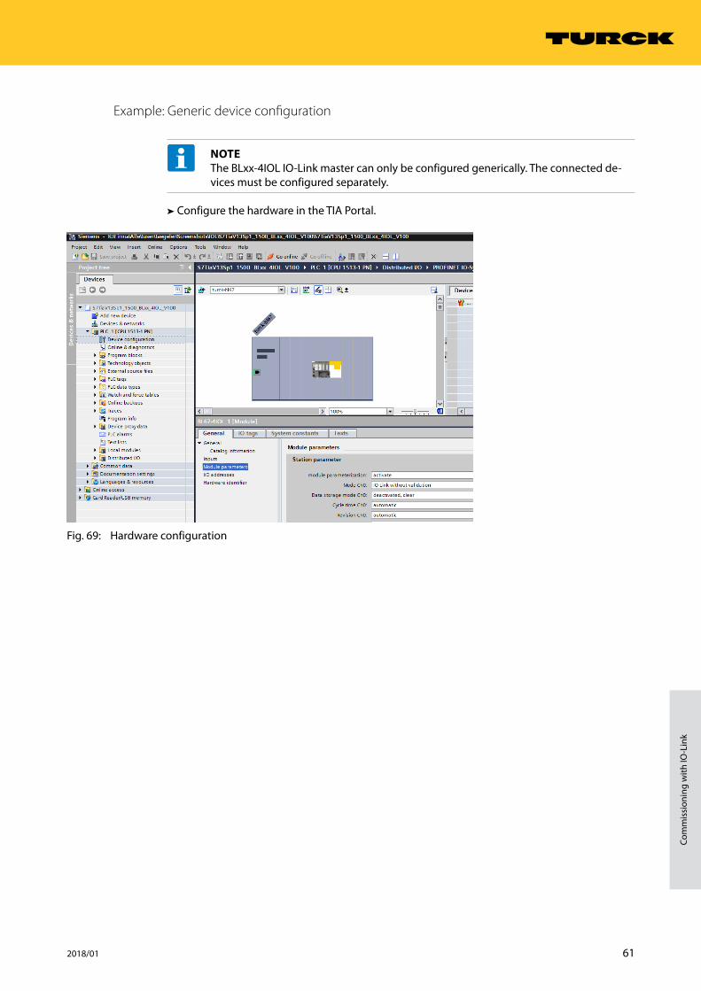
Example: Generic device configuration
NOTEThe BLxx-4IOL IO-Link master can only be configured generically. The connected de-vices must be configured separately.
➤➤ Configure the hardware in the TIA Portal.
Fig. 69: Hardware configuration
62 Hans Turck GmbH & Co. KG | T +49 208 4952-0 | F +49 208 4952-264 | [email protected] | www.turck.com
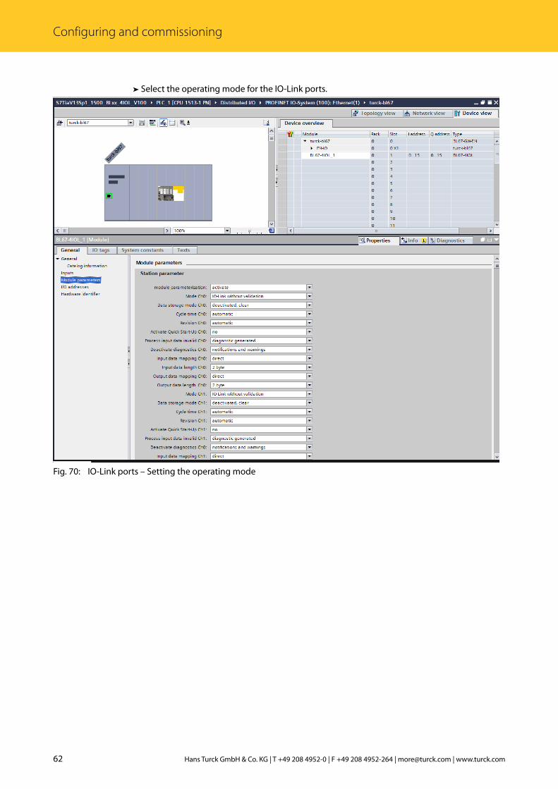
Configuring and commissioning
➤➤ Select the operating mode for the IO-Link ports.
Fig. 70: IO-Link ports – Setting the operating mode

63 2018/01
Com
mis
sion
ing
with
IO-L
ink
➤➥ Online mode enables the process values to be observed if an IO-Link device is connected.
Fig. 71: Online mode – Observing process values
64 Hans Turck GmbH & Co. KG | T +49 208 4952-0 | F +49 208 4952-264 | [email protected] | www.turck.com
Configuring and commissioning
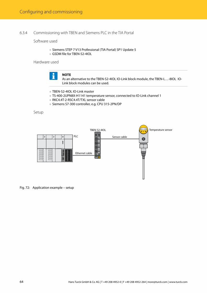
6.3.4 Commissioning with TBEN and Siemens PLC in the TIA Portal
Software used
■ Siemens STEP 7 V13 Professional (TIA Portal) SP1 Update 5 ■ GSDM file for TBEN-S2-4IOL
Hardware used
NOTEAs an alternative to the TBEN-S2-4IOL IO-Link block module, the TBEN-L…-8IOL IO-Link block modules can be used.
■ TBEN-S2-4IOL IO-Link master ■ TS-400-2UPN8X-H1141 temperature sensor, connected to IO-Link channel 1 ■ RKC4.4T-2-RSC4.4T/TXL sensor cable ■ Siemens S7-300 controller, e.g. CPU 315-2PN/DP
Setup
Fig. 72: Application example – setup
Ethernet cable
PLC Sensor cable
TBEN-S2-4IOL Temperature sensor

65 2018/01
Com
mis
sion
ing
with
IO-L
ink
Example: Specific device configuration
NOTEThe TBEN-S2-4IOL IO-Link master can be configured specifically. The connected devices can be configured via the PLC program.
➤➤ Configure the hardware in the TIA Portal.
Fig. 73: Hardware configuration

66 Hans Turck GmbH & Co. KG | T +49 208 4952-0 | F +49 208 4952-264 | [email protected] | www.turck.com
Configuring and commissioning
➤➤ Select the operating mode for the IO-Link ports.
Fig. 74: IO-Link ports – Setting the operating mode
NOTEThe I/O addresses are automatically displayed when a specific module is selected.

67 2018/01
Com
mis
sion
ing
with
IO-L
ink
➤➤ Select an IO-Link device for the required port.
Fig. 75: Selecting the IO-Link device
➤➥ Online mode enables the process values to be observed.
Fig. 76: Online mode – Observing process values
68 Hans Turck GmbH & Co. KG | T +49 208 4952-0 | F +49 208 4952-264 | [email protected] | www.turck.com
Setting
7 SettingThe following examples describe the setting of IO-Link devices during operation. The following scenarios are possible here: ■ Setting with a programmable gateway from VN03-00 and CODESYS 3 ■ Setting with a programmable gateway and CODESYS 2 ■ Setting with a Siemens PLC in Simatic Manager ■ Setting with a Siemens PLC in the TIA Portal
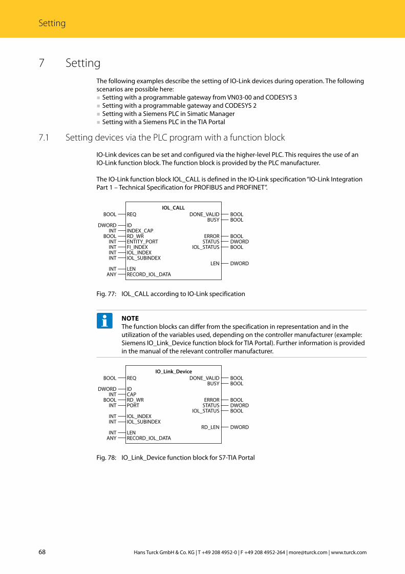
7.1 Setting devices via the PLC program with a function block
IO-Link devices can be set and configured via the higher-level PLC. This requires the use of an IO-Link function block. The function block is provided by the PLC manufacturer.
The IO-Link function block IOL_CALL is defined in the IO-Link specification “IO-Link Integration Part 1 – Technical Specification for PROFIBUS and PROFINET”.
Fig. 77: IOL_CALL according to IO-Link specification
NOTEThe function blocks can differ from the specification in representation and in the utilization of the variables used, depending on the controller manufacturer (example: Siemens IO_Link_Device function block for TIA Portal). Further information is provided in the manual of the relevant controller manufacturer.
Fig. 78: IO_Link_Device function block for S7-TIA Portal
IOL_CALLREQ
IDINDEX_CAPRD_WRENTITY_PORTFI_INDEXIOL_INDEXIOL_SUBINDEX
LENRECORD_IOL_DATA
BOOL
DWORDINT
BOOLINTINTINTINT
INTANY
BOOLBOOL
BOOLDWORDBOOL
DWORD
DONE_VALIDBUSY
ERRORSTATUS
IOL_STATUS
LEN
IO_Link_DeviceREQ
IDCAPRD_WRPORT
IOL_INDEXIOL_SUBINDEX
LENRECORD_IOL_DATA
BOOL
DWORDINT
BOOLINT
INTINT
INTANY
BOOLBOOL
BOOLDWORDBOOL
DWORD
DONE_VALIDBUSY
ERRORSTATUS
IOL_STATUS
RD_LEN

69 2018/01
Com
mis
sion
ing
with
IO-L
ink
Fig. 79: IO_Link_Device function block for CODESYS3
IOL_CALL function block – input variables
The following description of the input variables has been taken from the IO-Link specification.
Name as per IO-Link specification
Data type Meaning
REQ BOOL 0 1 0: Send command
ID DWORD Address of the IO-Link master – 3 S CODESYS: Slot number of the IO-Link master module – Siemens CPU 1200er, 1500er (PROFIBUS/PROFINET): Hardware identifier of the IO-Link master module – Siemens CPU 300er, 400er (PROFIBUS/PROFINET): Start address of the input data of the IO-Link master module
ITFMODULE Device name of the IO-Link master
Device name of the IO-Link master
INDEX_CAP INT Function block instance: 251…254
RD_WR BOOL 0: Read access1: Write access
ENTITY_PORT INT Address of the IO-Link port to be accessed.
FI_INDEX INT Fixed value (65098): Defines the access as IO-Link function block IOL_CALL
IOL_INDEX INT Number of the IO-Link index to be read or written.
IOL_SUBINDEX INT Number of the IO-Link subindex to be read or written
LEN INT Length of the data to be read or written
RECORD_IOL_DATA Source or target area of the data to be read or written
IO_Link_DeviceREQ
ITFMODULECAPRD_WRPORT
IOL_INDEXIOL_SUBINDEX
LENRECORD_IOL_DATA
BOOL
DWORDINT
BOOLINT
INTINT
INTANY
BOOLBOOL
BOOLDWORDBOOL
DWORD
DONE_VALIDBUSY
ERRORSTATUS
IOL_STATUS
RD_LEN
70 Hans Turck GmbH & Co. KG | T +49 208 4952-0 | F +49 208 4952-264 | [email protected] | www.turck.com
Setting
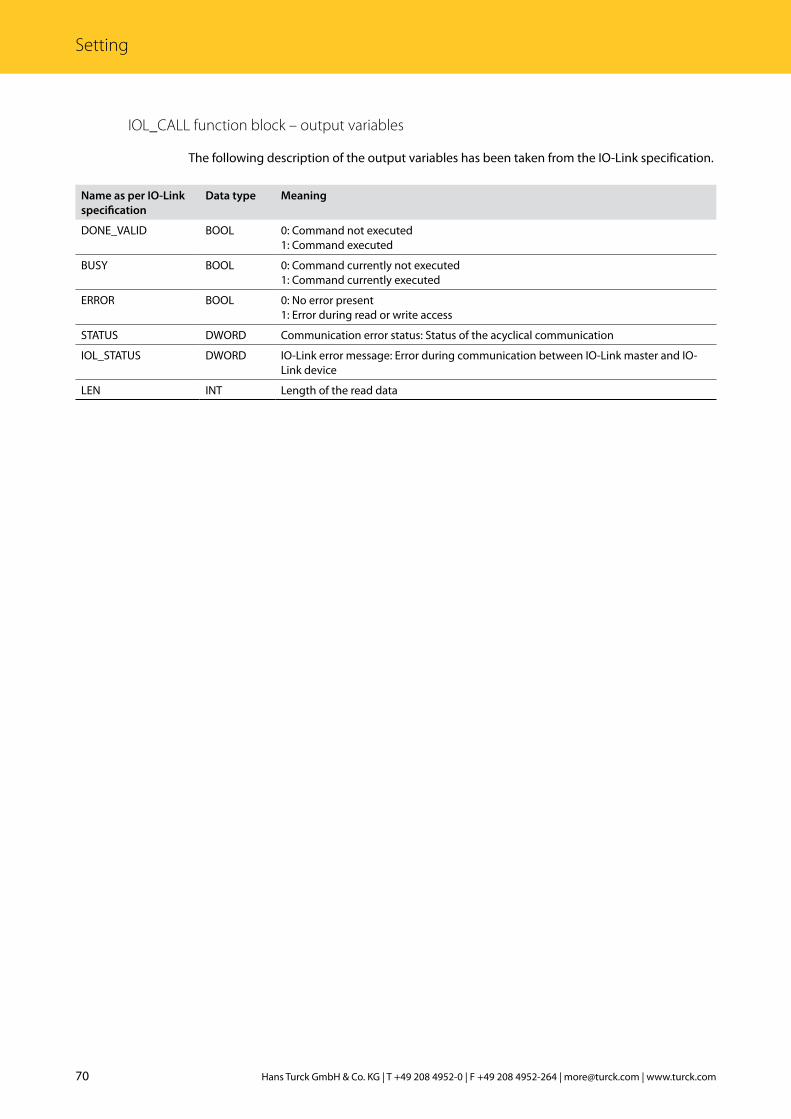
IOL_CALL function block – output variables
The following description of the output variables has been taken from the IO-Link specification.
Name as per IO-Link specification
Data type Meaning
DONE_VALID BOOL 0: Command not executed1: Command executed
BUSY BOOL 0: Command currently not executed1: Command currently executed
ERROR BOOL 0: No error present1: Error during read or write access
STATUS DWORD Communication error status: Status of the acyclical communication
IOL_STATUS DWORD IO-Link error message: Error during communication between IO-Link master and IO-Link device
LEN INT Length of the read data
71 2018/01
Com
mis
sion
ing
with
IO-L
ink
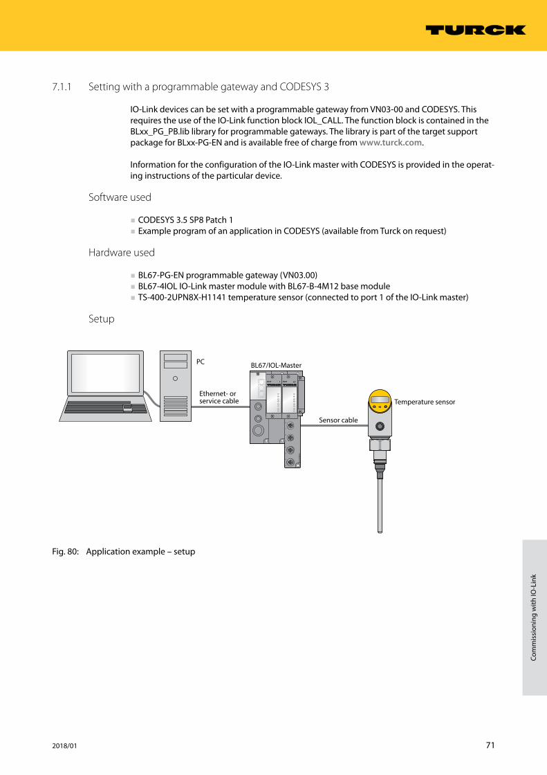
7.1.1 Setting with a programmable gateway and CODESYS 3
IO-Link devices can be set with a programmable gateway from VN03-00 and CODESYS. This requires the use of the IO-Link function block IOL_CALL. The function block is contained in the BLxx_PG_PB.lib library for programmable gateways. The library is part of the target support package for BLxx-PG-EN and is available free of charge from www.turck.com.
Information for the configuration of the IO-Link master with CODESYS is provided in the operat-ing instructions of the particular device.
Software used
■ CODESYS 3.5 SP8 Patch 1 ■ Example program of an application in CODESYS (available from Turck on request)
Hardware used
■ BL67-PG-EN programmable gateway (VN03.00) ■ BL67-4IOL IO-Link master module with BL67-B-4M12 base module ■ TS-400-2UPN8X-H1141 temperature sensor (connected to port 1 of the IO-Link master)
Setup
Fig. 80: Application example – setup
BL6
7-B
-4M
12-P
0
1
2
3
4
5
6
7
DBL67DBL67
1
0
2
4
6
3
5
7
Ethernet- orservice cable
PC
Sensor cable
BL67/IOL-Master
Temperature sensor
72 Hans Turck GmbH & Co. KG | T +49 208 4952-0 | F +49 208 4952-264 | [email protected] | www.turck.com
Setting
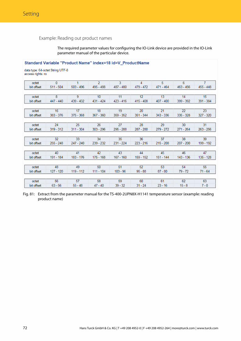
Example: Reading out product names
The required parameter values for configuring the IO-Link device are provided in the IO-Link parameter manual of the particular device.
Fig. 81: Extract from the parameter manual for the TS-400-2UPN8X-H1141 temperature sensor (example: reading product name)
73 2018/01
Com
mis
sion
ing
with
IO-L
ink
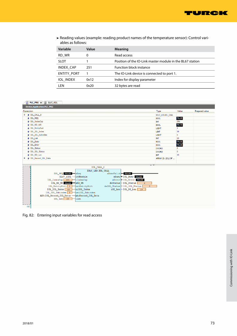
➤➤ Reading values (example: reading product names of the temperature sensor): Control vari-ables as follows:
Variable Value Meaning
RD_WR 0 Read access
SLOT 1 Position of the IO-Link master module in the BL67 station
INDEX_CAP 251 Function block instance
ENTITY_PORT 1 The IO-Link device is connected to port 1.
IOL_INDEX 0x12 Index for display parameter
LEN 0x20 32 bytes are read
Fig. 82: Entering input variables for read access
74 Hans Turck GmbH & Co. KG | T +49 208 4952-0 | F +49 208 4952-264 | [email protected] | www.turck.com
Setting
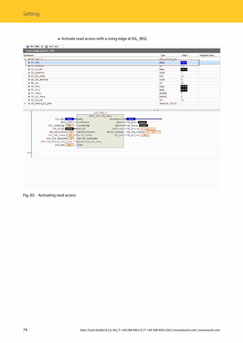
➤➤ Activate read access with a rising edge at IOL_REQ.
Fig. 83: Activating read access

75 2018/01
Com
mis
sion
ing
with
IO-L
ink
➤➥ The product name is displayed in the “READ” data array in hexadecimal code.
Fig. 84: “READ” process data array

76 Hans Turck GmbH & Co. KG | T +49 208 4952-0 | F +49 208 4952-264 | [email protected] | www.turck.com
Setting
Example: Writing values
The required parameter values of the IO-Link device are provided in the parameter manual of the particular IO-Link device.
Fig. 85: Extract from the parameter manual for the TS-400-2UPN8X-H1141 sensor (example: setting the display)

77 2018/01
Com
mis
sion
ing
with
IO-L
ink
➤➤ Writing values (example: Rotate display of the TS-400-2UPN8X-H1141 temperature sensor by 180° and set measured value refresh time to 200 ms): Control variables as follows:
Variable Value Meaning
RD_WR 1 Write access
SLOT 1 Position of the IO-Link master module in the BL67 station
INDEX_CAP 251 Function block instance
ENTITY_PORT 1 The IO-Link device is connected to port 1.
IOL_INDEX 0x55 Index for display parameter
LEN 1 1 byte is written
Fig. 86: Entering input variables for write access

78 Hans Turck GmbH & Co. KG | T +49 208 4952-0 | F +49 208 4952-264 | [email protected] | www.turck.com
Setting
➤➤ Enter value 5 to be written in array WRITE in order to rotate the display by 180° and set the measured value refresh time to 200 ms.
➤➤ Activate write access with a rising edge at REQ.
Fig. 87: Activating write access

79 2018/01
Com
mis
sion
ing
with
IO-L
ink
7.1.2 Setting with a programmable gateway and CODESYS 2
IO-Link devices can be set with a programmable gateway up to version 2 and CODESYS. This requires the use of the IO-Link function block IOL_CALL. The function block is contained in the BLxx_PG_PB.lib library for programmable gateways. The library is part of the target support package for BLxx-PG-EN and is available free of charge from www.turck.com.
Information for the configuration of the IO-Link master with CODESYS is provided in the operat-ing instructions of the particular device.
Software used
■ CODESYS 2.3 with BLxx_PG_PB.lib library ■ Example program of an application in CODESYS (available from Turck on request)
Hardware used
■ BL20-PG-EN programmable gateway ■ BL20-E-4IOL IO-Link master module ■ TS-400-2UPN8X-H1141 temperature sensor (connected to port 1 of the IO-Link master) ■ TBIL-M1-16DIP I/O hub (connected to Port 4 of the IO-Link master)
50.6
114.874.4
LED
����
�������
�����
����
���
�������������
���
����
C1 C3
C2 C4
C5
C6
C7
C873
107
44,7 32,2
150
1625,2
ø 4,3
54
M12 x 127,4
Fig. 88: Hardware components in the application example (programmable gateway, IO-Link master module, temperature sensor, IO-Link I/O hub)
80 Hans Turck GmbH & Co. KG | T +49 208 4952-0 | F +49 208 4952-264 | [email protected] | www.turck.com
Setting
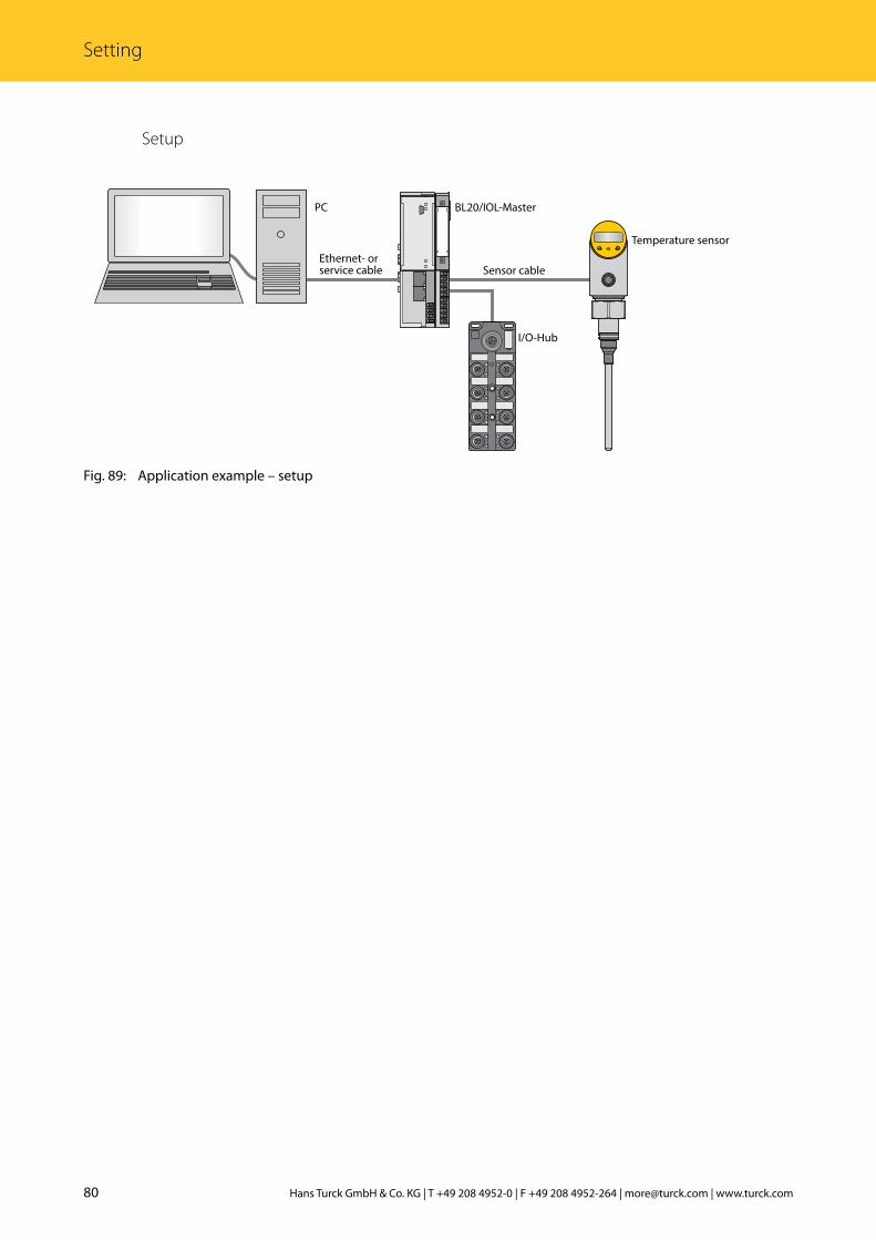
Setup
Fig. 89: Application example – setup
BL20-E-GW-EN
Temperature sensor
Ethernet- orservice cable
PC
Sensor cable
BL20/IOL-Master
I/O-Hub

81 2018/01
Com
mis
sion
ing
with
IO-L
ink
Example: Reading out product names
The required parameter values for configuring the IO-Link device are provided in the IO-Link parameter manual of the particular device.
Fig. 90: Extract from the parameter manual for the TBIL-M1-16DIP IO-Link I/O hub (example: reading product name)

82 Hans Turck GmbH & Co. KG | T +49 208 4952-0 | F +49 208 4952-264 | [email protected] | www.turck.com
Setting
➤➤ Reading values (example: Read product name of the IO-Link I/O hub): Control variables as follows:
Variable Value Meaning
RD_WR 0 Read access
SLOT 1 Position of the IO-Link master module in the BL67 station
INDEX_CAP 251 Function block instance
ENTITY_PORT 4 The IO-Link device is connected to port 4.
IOL_INDEX 0x12 Index for display parameter
LEN 0x20 32 bytes are read
Fig. 91: Entering input variables for read access

83 2018/01
Com
mis
sion
ing
with
IO-L
ink
➤➤ Activate read access with a rising edge at REQ.
Fig. 92: Activating read access
84 Hans Turck GmbH & Co. KG | T +49 208 4952-0 | F +49 208 4952-264 | [email protected] | www.turck.com
Setting
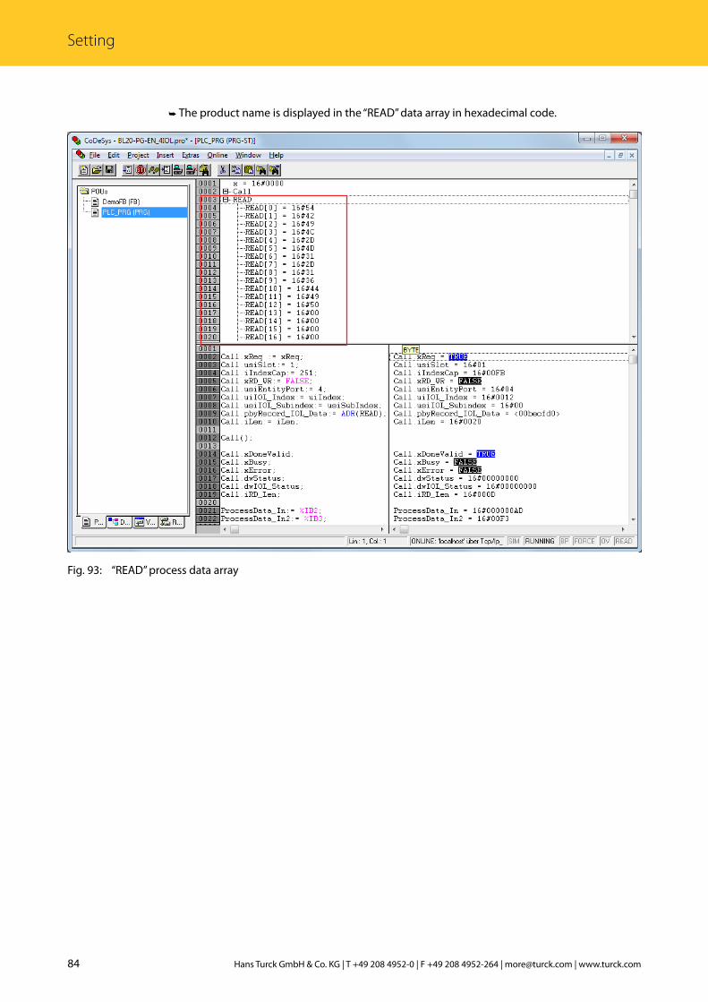
➤➥ The product name is displayed in the “READ” data array in hexadecimal code.
Fig. 93: “READ” process data array
85 2018/01
Com
mis
sion
ing
with
IO-L
ink
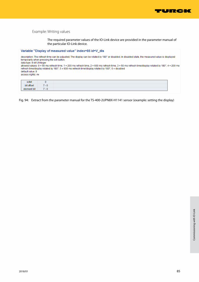
Example: Writing values
The required parameter values of the IO-Link device are provided in the parameter manual of the particular IO-Link device.
Fig. 94: Extract from the parameter manual for the TS-400-2UPN8X-H1141 sensor (example: setting the display)

86 Hans Turck GmbH & Co. KG | T +49 208 4952-0 | F +49 208 4952-264 | [email protected] | www.turck.com
Setting
➤➤ Writing values (example: Rotate display of the TS-400-2UPN8X-H1141 temperature sensor by 180° and set measured value refresh time to 200 ms): Control variables as follows:
Variable Value Meaning
RD_WR 1 Write access
SLOT 1 Position of the IO-Link master module in the BL67 station
INDEX_CAP 251 Function block instance
ENTITY_PORT 1 The IO-Link device is connected to port 1.
IOL_INDEX 0x55 Index for display parameter
LEN 1 1 byte is written
Fig. 95: Entering input variables for write access
87 2018/01
Com
mis
sion
ing
with
IO-L
ink
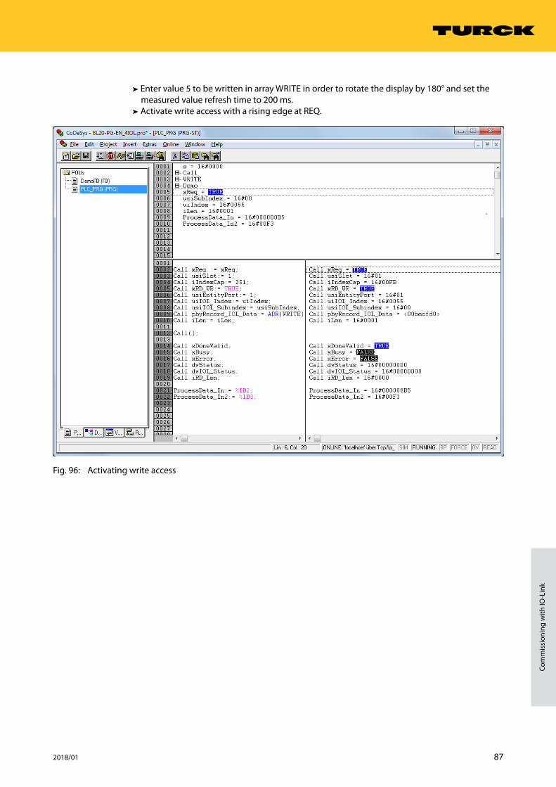
➤➤ Enter value 5 to be written in array WRITE in order to rotate the display by 180° and set the measured value refresh time to 200 ms.
➤➤ Activate write access with a rising edge at REQ.
Fig. 96: Activating write access

88 Hans Turck GmbH & Co. KG | T +49 208 4952-0 | F +49 208 4952-264 | [email protected] | www.turck.com
Setting
7.1.3 Setting with an S7-1200/1500 Siemens PLC and TIA Portal
IO-Link devices can be set and configured via a Turck-IO-Link master on a Siemens S7-1200/1500 PLC and STEP7 V12/13 TIA Portal. This requires the use of the IO-Link function block IOL_DEVICE and the GSDML file of the IO-Link master. The function block is provided in the li-brary IO_Link_Library_v13_SP1. The library is available on the website of the PLC manufacturer. The GSDML file is available for download from www.turck.com.
Information for the configuration of the IO-Link master with STEP7 V13 TIA Portal is provided in the operating instructions of the particular device.
Software used
■ Siemens STEP 7 V13 Professional (TIA Portal) SP1 Update 5 ■ GSDML file of the IO-Link master ■ Example program (available from Turck on request)
Hardware used
NOTEAs an alternative to the TBEN-S2-4IOL IO-Link block module, the TBEN-L…-8IOL IO-Link block modules can be used.
■ Siemens S7 controller, e.g. with CPU 1513-1PN ■ TBEN-S2-4IOL IO-Link master ■ TS-400-2UPN8X-H1141 temperature sensor (connected to port 1 of the IO-Link master)
Setup
Fig. 97: Application example – setup
Ethernet cable
PLC Sensor cable
TBEN-S2-4IOL Temperature sensor
89 2018/01
Com
mis
sion
ing
with
IO-L
ink
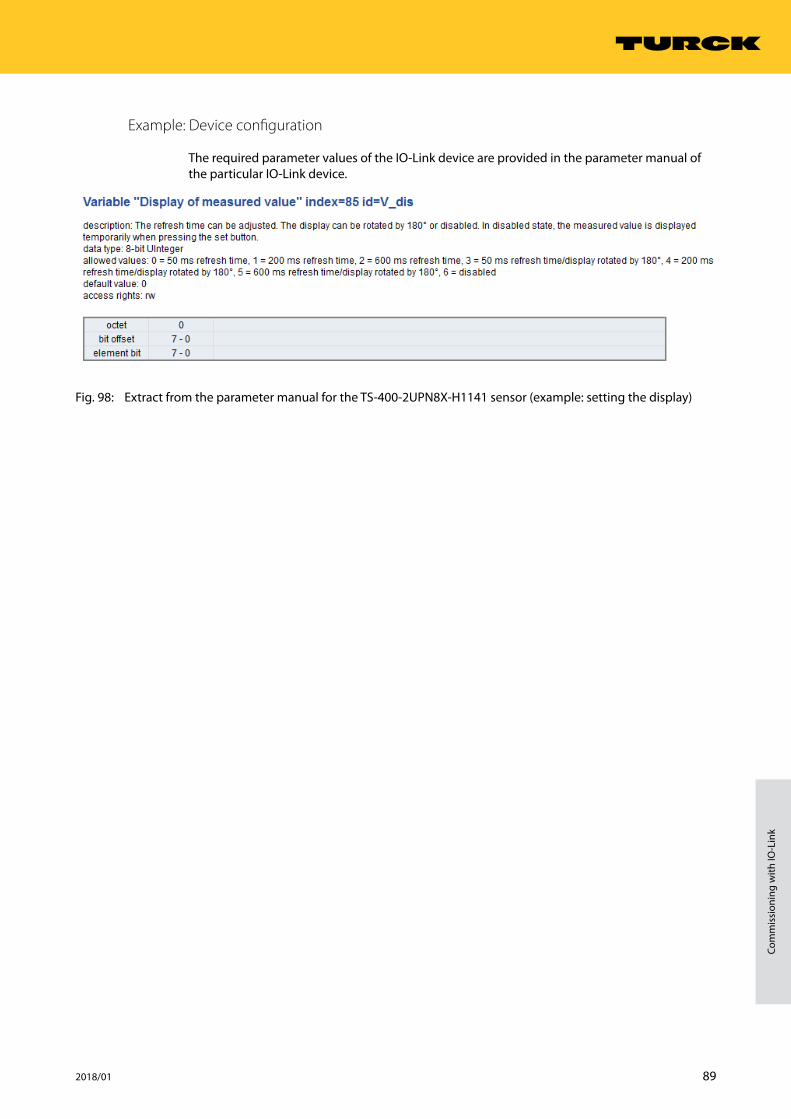
Example: Device configuration
The required parameter values of the IO-Link device are provided in the parameter manual of the particular IO-Link device.
Fig. 98: Extract from the parameter manual for the TS-400-2UPN8X-H1141 sensor (example: setting the display)

90 Hans Turck GmbH & Co. KG | T +49 208 4952-0 | F +49 208 4952-264 | [email protected] | www.turck.com
Setting
The processes are visualized in the example program in the “IOL1P1” visualization table.
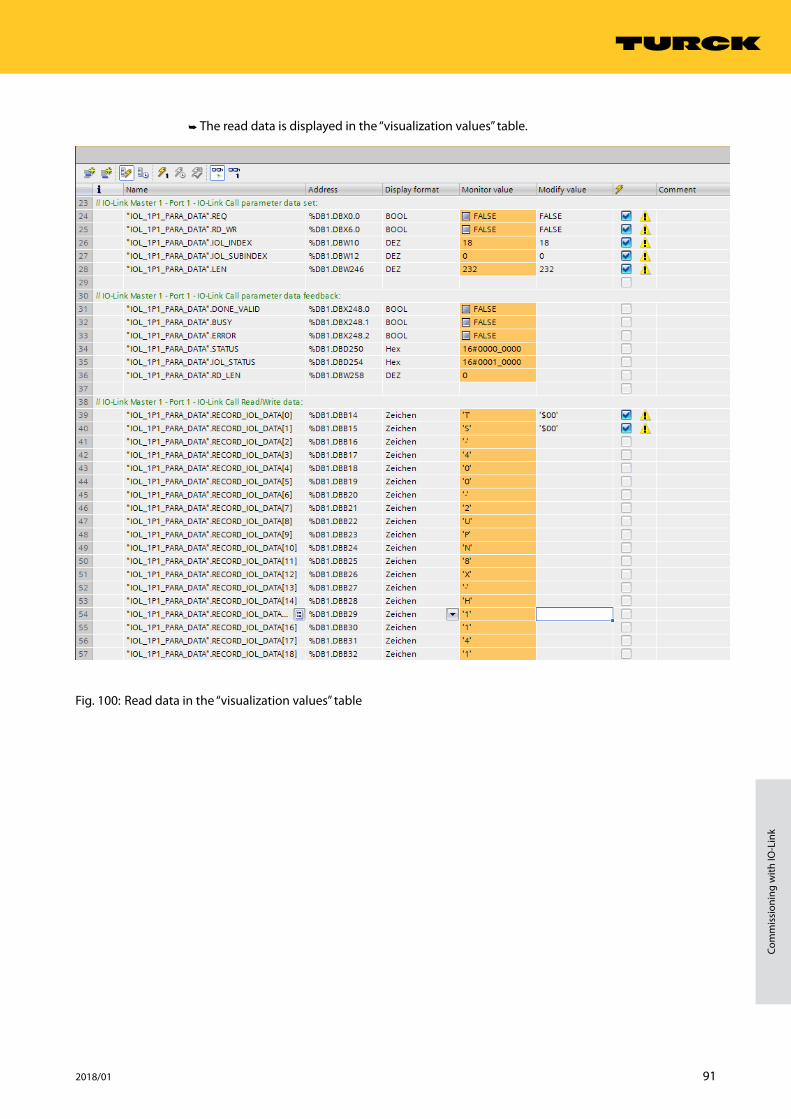
➤➤ Reading values (example: reading product names of the temperature sensor): Control vari-ables as follows:
Variable Value Meaning
RD_WR 0 Read access
CAP 251 Function block instance
PORT 1 The temperature sensor is connected to port 1.
IOL_INDEX 18 Index for display parameter
LEN 32 32 bytes are read
Fig. 99: Entering input variables for read access
➤➤ Activate read access with a rising edge at REQ.
91 2018/01
Com
mis
sion
ing
with
IO-L
ink
➤➥ The read data is displayed in the “visualization values” table.
Fig. 100: Read data in the “visualization values” table
92 Hans Turck GmbH & Co. KG | T +49 208 4952-0 | F +49 208 4952-264 | [email protected] | www.turck.com
Setting
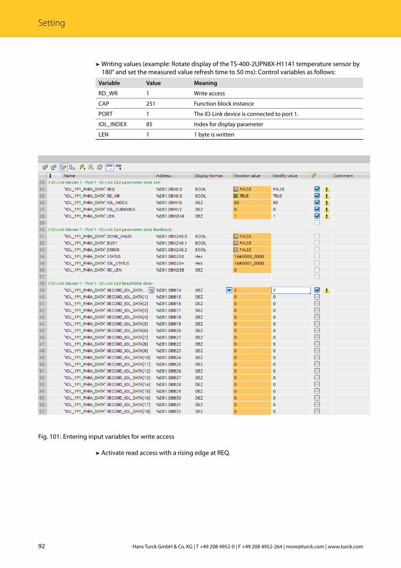
➤➤ Writing values (example: Rotate display of the TS-400-2UPN8X-H1141 temperature sensor by 180° and set the measured value refresh time to 50 ms): Control variables as follows:
Variable Value Meaning
RD_WR 1 Write access
CAP 251 Function block instance
PORT 1 The IO-Link device is connected to port 1.
IOL_INDEX 85 Index for display parameter
LEN 1 1 byte is written
Fig. 101: Entering input variables for write access
➤➤ Activate read access with a rising edge at REQ.

93 2018/01
Com
mis
sion
ing
with
IO-L
ink
7.1.4 Setting with an S7-300/400 Siemens PLC and STEP7 V5.5
IO-Link devices can be set and configured via a Turck-IO-Link master on a Siemens S7-300/400 PLC and STEP7 V5.5. This requires the use of the IO-Link function block IOL_CALL and the GS-DML file of the IO-Link master. The function block is available from the PLC manufacturer. The GSDML file is available for download from www.turck.com.
Information for the configuration of the IO-Link master with STEP7 V5.5 is provided in the oper-ating instructions of the particular device.
Software used
■ Siemens STEP7 V5.5 (Simatic Manager) ■ GSDML file for BL67-GW-EN ■ Example program (available from Turck on request)
Hardware used
■ BL67-GW-EN multiprotocol gateway (VN03-00) ■ BL67-B-4M12 base module with BL67-4IOL IO-Link master module ■ TS-400-2UPN8X-H1141 temperature sensor ■ Siemens S7 controller, e.g. CPU 315-2PN/DP
Example: Device configuration
The required parameter values of the IO-Link device are provided in the parameter manual of the particular IO-Link device.
Fig. 102: Extract from the parameter manual for the TS-400-2UPN8X-H1141 sensor (example: setting the display)

94 Hans Turck GmbH & Co. KG | T +49 208 4952-0 | F +49 208 4952-264 | [email protected] | www.turck.com
Setting
Fig. 103: Extract from the parameter manual for the TBIL-M1-16DIP IO-Link I/O hub (example: setting the display)

95 2018/01
Com
mis
sion
ing
with
IO-L
ink
The processes are visualized in the example program in the “HMI” variable table. The process data is shown in the “Sensor1” and “Sensor2” variable table.
➤➤ Reading values (example: Read product name of the IO-Link I/O hub): Control variables as follows:
Variable Value Meaning
RD_WR 0 Read access
ID 30 Start address of the output data of the module as per hardware configuration
INDEX_CAP 251 Function block instance
ENTITY_PORT 4 The IO-Link hub is connected to port 4.
IOL_INDEX 0x12 Index for display parameter
LEN 32 32 bytes are read
Fig. 104: Entering input variables for read access

96 Hans Turck GmbH & Co. KG | T +49 208 4952-0 | F +49 208 4952-264 | [email protected] | www.turck.com
Setting
➤➤ Activate read access with a rising edge at REQ.
Fig. 105: Activating read access
97 2018/01
Com
mis
sion
ing
with
IO-L
ink
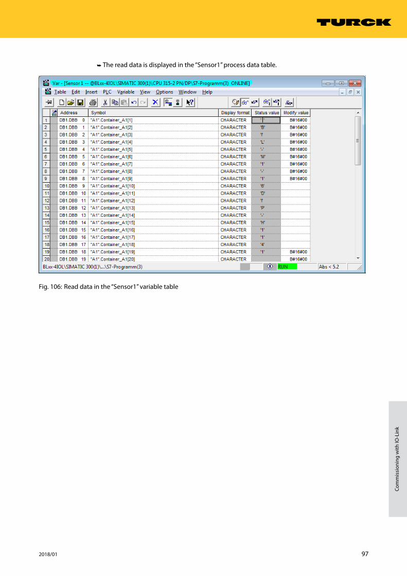
➤➥ The read data is displayed in the “Sensor1” process data table.
Fig. 106: Read data in the “Sensor1” variable table

98 Hans Turck GmbH & Co. KG | T +49 208 4952-0 | F +49 208 4952-264 | [email protected] | www.turck.com
Setting
➤➤ Writing values (example: Rotate display of the TS-400-2UPN8X-H1141 temperature sensor by 180° and set measured value refresh time to 200 ms): Control variables as follows:
Variable Value Meaning
RD_WR 1 Write access
ID 1 Position of the IO-Link master module in the BL67 station
INDEX_CAP 251 Function block instance
ENTITY_PORT 1 The IO-Link device is connected to port 1.
IOL_INDEX 0x55 Index for display parameter
LEN 1 1 byte is written
Fig. 107: Entering input variables for write access

99 2018/01
Com
mis
sion
ing
with
IO-L
ink
➤➤ Enter value 5 to be written in the variable table under “Control value” in order to rotate the display by 180° and set the measured value refresh time to 200 ms.
Fig. 108: Entering a control value for index 85 (0x55)

100 Hans Turck GmbH & Co. KG | T +49 208 4952-0 | F +49 208 4952-264 | [email protected] | www.turck.com
Setting
➤➤ Activate write access with a rising edge at REQ.
Fig. 109: Activating write access

101 2018/01
Com
mis
sion
ing
with
IO-L
ink
8 OperationThe communication system operates with a 24 V signal. If a transmission is not successful, the telegram is automatically repeated twice. If the second repeat attempt is not successful, the IO-Link master detects a communication abort. The error is automatically reported to the higher-level controller.
IO-Link devices can be set for the specific application or operated without any special settings. If no settings are required in the IO-Link device, the signals are forwarded directly to the higher control level.
Fig. 110: Overview – operating IO-Link devices
Further information on operating the IO-Link masters and the IO-Link devices is provided in the operating instructions of the particular device.
Parameterizing tool orIO-Link function block
EtherNet/IP™Modbus TCP
BLxx-IO-Link MasterTBEN-IO-Link Master
PROFINET
GSDMLfor IO-Link
Setting required
Operating the device
Direct signal transmission
Setting not required
102 Hans Turck GmbH & Co. KG | T +49 208 4952-0 | F +49 208 4952-264 | [email protected] | www.turck.com
Operation
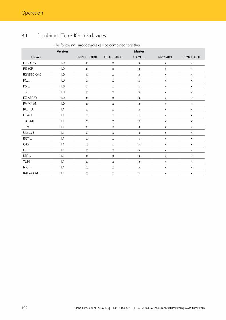
8.1 Combining Turck IO-Link devices
The following Turck devices can be combined together:
Version Master
Device TBEN-L…-8IOL TBEN-S-4IOL TBPN-… BL67-4IOL BL20-E-4IOL
Li…-Q25 1.0 x x x x x
Ri360P 1.0 x x x x x
B2N360-Q42 1.0 x x x x x
PC… 1.0 x x x x x
PS… 1.0 x x x x x
TS… 1.0 x x x x x
EZ-ARRAY 1.0 x x x x x
FM(X)-IM 1.0 x x x x x
RU…U 1.1 x x x x x
DF-G1 1.1 x x x x x
TBIL-M1 1.1 x x x x x
TTM 1.1 x x x x x
Uprox 3 1.1 x x x x x
BCT… 1.1 x x x x x
Q4X 1.1 x x x x x
LE… 1.1 x x x x x
LTF… 1.1 x x x x x
TL50 1.1 x x x x x
NIC… 1.1 x x x x x
IM12-CCM… 1.1 x x x x x

103 2018/01
Com
mis
sion
ing
with
IO-L
ink

D900634 | 2018/01
*D900634*
28 subsidiaries and over 60 representations worldwide!
www.turck.com