Invitation for Bid - procure.stateuniv.state.il.us · Invitation for Bid No. 1MCA1403 Gas Boiler...
122
Invitation for Bid No. 1MCA1403 Gas Boiler Replacement Project PROPOSAL ISSUED DATE: July 12, 2013 PROPOSAL DUE DATE: August 13, 2013 PROPOSAL DUE TIME: 2:00 PM Local Time NOTE: Proposer must complete the enclosed Standard Qualifications, Certifications, Representations, and Disclosures (Exhibits A, B, & C). Failure to complete and return these forms with Proposer’s response may result in its being considered non-responsive to this solicitation. Proposer is also required to be registered with the State of Illinois Board of Elections, prior to the solicitation opening. Please include a copy of the Board of Elections Certification in your solicitation response. All questions regarding general Bid Proposal procedures should be directed to: Mike Adams OBFS, UIUC Purchasing 212 Illini Plaza 1817 S. Neil St. Champaign, IL 61820 (217) 244-4916 [email protected] Send or deliver Bid Proposal to: University of Illinois Purchasing Division ATTN: Bid Desk 212 Illini Plaza 1817 S. Neil St. Champaign, IL 61820 Clearly mark 1MCA1403 on the outside of all packages. BIDDERS SHOULD SUBMIT THE FOLLOWING WITH THEIR RESPONSE: Subject Matter # of Originals # of Hard Copies # of CDs or Other Electronic Media (submit documentation using .pdf format) Bidders should submit the following with their response 1 3 1
Transcript of Invitation for Bid - procure.stateuniv.state.il.us · Invitation for Bid No. 1MCA1403 Gas Boiler...

Invitation for Bid
No. 1MCA1403
Gas Boiler Replacement Project
PROPOSAL ISSUED DATE: July 12, 2013
PROPOSAL DUE DATE: August 13, 2013
PROPOSAL DUE TIME: 2:00 PM Local Time NOTE: Proposer must complete the enclosed Standard Qualifications, Certifications, Representations, and Disclosures (Exhibits A, B, & C). Failure to complete and return these forms with Proposer’s response may result in its being considered non-responsive to this solicitation. Proposer is also required to be registered with the State of Illinois Board of Elections, prior to the solicitation opening. Please include a copy of the Board of Elections Certification in your solicitation response.
All questions regarding general Bid Proposal procedures should be directed to:
Mike Adams OBFS, UIUC Purchasing 212 Illini Plaza 1817 S. Neil St. Champaign, IL 61820 (217) 244-4916 [email protected]
Send or deliver Bid Proposal to: University of Illinois Purchasing Division ATTN: Bid Desk 212 Illini Plaza 1817 S. Neil St. Champaign, IL 61820
Clearly mark 1MCA1403 on the outside of all packages.
BIDDERS SHOULD SUBMIT THE FOLLOWING WITH THEIR RESPONSE: Subject Matter # of Originals # of Hard
Copies # of CDs or Other Electronic Media (submit documentation using .pdf format)
Bidders should submit the following with their response
1 3 1

Purchasing Division Illini Plaza, Suite 212 1817 South Neil Street Champaign, IL 61820-5752 Invitation for Bid
No 1MCA1403
July 12, 2013
August 13, 2013 Bid is due by
2:00 PM Local Time Bid Proposal Date Date Bid Due
Deliveries are to be Urbana Champaign unless otherwise designated.
Company Name Address Suite, PO Box # City, State, Zip
F. O. B.
Shipping Point Shipping Weight Delivery Time (Time required after receipt of order)
Payment Terms %
days
(discount)
Net days
THE FOLLOWING GENERAL TERMS AND CONDITIONS WILL APPLY UNLESS OTHERWISE SPECIFIED IN THE BID PROPOSAL
THIS TRANSACTION is subject to Procurement Rules of the Chief Procurement Officer for Public Institutions of Higher Education.
TAXES: Sales to the University are exempt from Illinois R.O.T., Use, S.O.T., Service Use Tax, and Leasing Tax. FEDERAL TAXES are exempted. Certificate will be furnished upon request. SPECIFICATIONS: Unless otherwise indicated, any reference to trade names and specific manufacturers’ numbers or descriptions are used to establish minimum quality and/or performance characteristics. Any commodity (or service) of an approved equal or better will be considered. Give complete specifications for any substitutions offered. TIME is of essence, therefore accurate delivery schedules may be considered in making an award. DISCOUNTS for prompt payment shall be shown hereon. Discount periods will be computed from the date when acceptable merchandise has been received, or receipt of invoice, whichever is later. PACKING, DEPOSITS and OTHER COSTS will not be allowed in billing unless included in your Bid Proposal. SHIPMENTS are to be fully insured and made by the most expeditious method consistent with customs of the trade, terms of the Bid Proposal, weight and value of the merchandise and current tariff regulations. STANDARD WARRANTIES must be stated. When appropriate, you may submit your Bid Proposal on any of the items listed, and we also reserve the right to accept or reject all or part of your offer.
The undersigned offers the prices, terms, and delivery in this bid proposal. Vendor Name
(Signature of responsible officer)
Date
Buyer Mike Adams
Note: Respondent must complete the enclosed Standard Qualifications, Certifications, Representations, and Disclosures Attachment (Exhibits A, B, & C). Failure to complete and return the enclosed Exhibits A, B, & C may result in your offer being considered as "non-responsive" to this solicitation. AVAILABILITY OF DOCUMENTS: All State Universities in Illinois publish their competitive Bid/RFP and other
procurement notices, as well as award information at: http://www.procure.stateuniv.state.il.us
Firms intending to respond to any posted requirement are encouraged to visit that site to insure that they have
received a complete and current set of documents. Some notices may provide a downloadable copy of the
pertinent procurement documents, as well as any amendments to those documents. Any firm receiving a copy of
procurement documents from a third party is solely responsible for insuring that they have received all necessary
procurement documentation, including amendments. The issuing University is not responsible for insuring that all
or any procurement documentation is received by a firm that is not formally registered with the issuing University.
Furnish new dual-fuel packaged water-tube steam generating boiler.
Bid Total $___________________________
Note Mandatory Pre-Bid Meeting to be held at the North Conference Trailer at the Abbott Power Plant
on July 24, 2013 at 10AM.

Bid No: 1MCA1403
Page 3 of 38
STATE OF ILLINOIS REQUIREMENT FOR ALL BIDDERS
Please Read Carefully Before Responding.
If you wish to submit a bid or proposal in response to this solicitation and are required to register with the State Board of Elections, please submit a copy of your certificate of registration with your bid or proposal. Compliance with Public Act 095-0971 (Registration with State Board of Elections)
If you have not already reviewed Public Act 095-0971, which went into effect on January 1, 2009, we strongly recommend that you do so immediately. The Act is available at http://www.ilga.gov/legislation/publicacts/fulltext.asp?Name=095-0971. The Act was amended by P.A. 095-1038 effective March 11, 2009, and the amendment is available at http://www.ilga.gov/legislation/publicacts/fulltext.asp?Name=095-1038.
STATE BOARD OF ELECTIONS CERTIFICATE OF REGISTRATION EXAMPLE
Bid No: 1MCA1403
Page 4 of 38
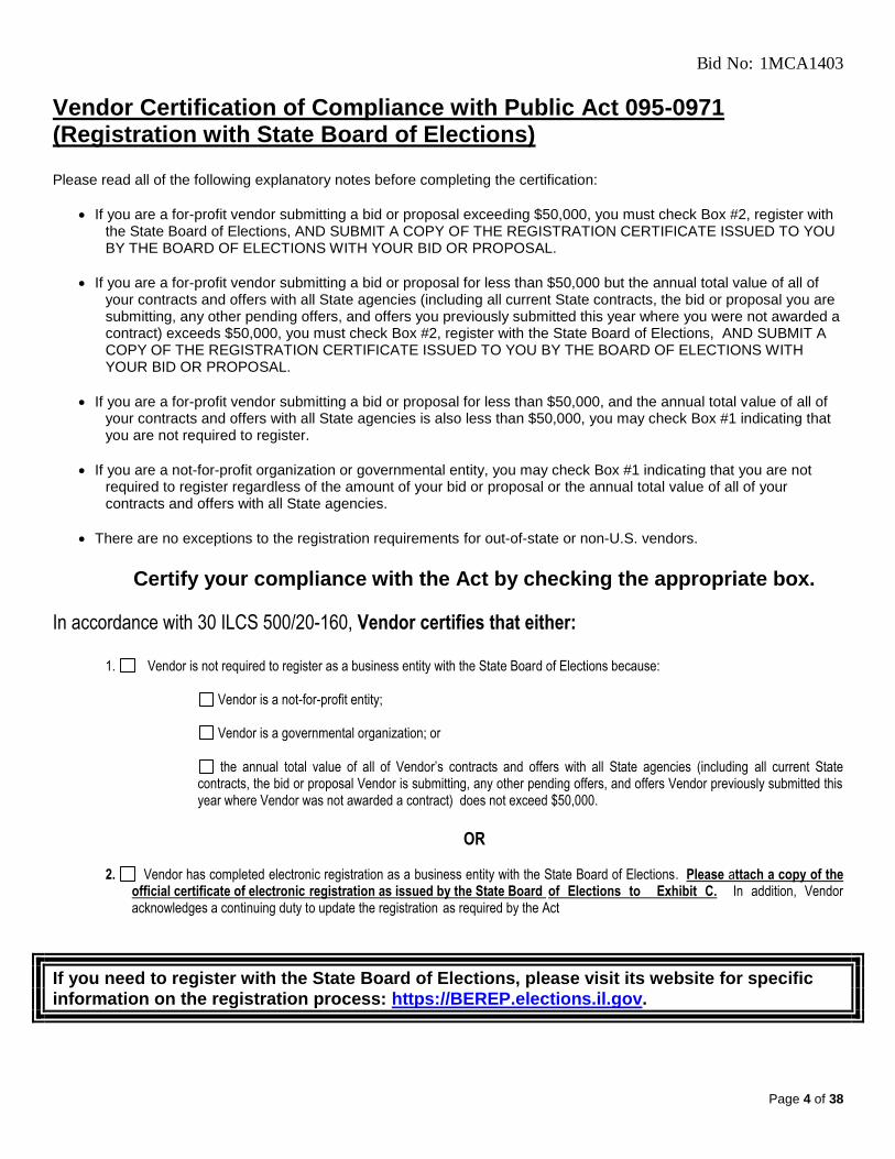
Vendor Certification of Compliance with Public Act 095-0971 (Registration with State Board of Elections)
Please read all of the following explanatory notes before completing the certification:
If you are a for-profit vendor submitting a bid or proposal exceeding $50,000, you must check Box #2, register with the State Board of Elections, AND SUBMIT A COPY OF THE REGISTRATION CERTIFICATE ISSUED TO YOU BY THE BOARD OF ELECTIONS WITH YOUR BID OR PROPOSAL.
If you are a for-profit vendor submitting a bid or proposal for less than $50,000 but the annual total value of all of your contracts and offers with all State agencies (including all current State contracts, the bid or proposal you are submitting, any other pending offers, and offers you previously submitted this year where you were not awarded a contract) exceeds $50,000, you must check Box #2, register with the State Board of Elections, AND SUBMIT A COPY OF THE REGISTRATION CERTIFICATE ISSUED TO YOU BY THE BOARD OF ELECTIONS WITH YOUR BID OR PROPOSAL.
If you are a for-profit vendor submitting a bid or proposal for less than $50,000, and the annual total value of all of your contracts and offers with all State agencies is also less than $50,000, you may check Box #1 indicating that you are not required to register.
If you are a not-for-profit organization or governmental entity, you may check Box #1 indicating that you are not required to register regardless of the amount of your bid or proposal or the annual total value of all of your contracts and offers with all State agencies.
There are no exceptions to the registration requirements for out-of-state or non-U.S. vendors.
Certify your compliance with the Act by checking the appropriate box.
In accordance with 30 ILCS 500/20-160, Vendor certifies that either:
1. Vendor is not required to register as a business entity with the State Board of Elections because:
Vendor is a not-for-profit entity;
Vendor is a governmental organization; or
the annual total value of all of Vendor’s contracts and offers with all State agencies (including all current State contracts, the bid or proposal Vendor is submitting, any other pending offers, and offers Vendor previously submitted this year where Vendor was not awarded a contract) does not exceed $50,000.
OR
2. Vendor has completed electronic registration as a business entity with the State Board of Elections. Please attach a copy of the
official certificate of electronic registration as issued by the State Board of Elections to Exhibit C. In addition, Vendor acknowledges a continuing duty to update the registration as required by the Act
If you need to register with the State Board of Elections, please visit its website for specific information on the registration process: https://BEREP.elections.il.gov.

Bid No: 1MCA1403
Page 5 of 38
ADDITIONAL STATE OF ILLINOIS REGISTRATION REQUIREMENTS
State of Illinois Business Entity Registration: Companies are required to register with the State of Illinois, including the Illinois Secretary of State and Illinois Department of Revenue, to comply with various required reporting obligations. It is critical that you complete this registration prior to submitting your proposal. In particular, bidders should be aware that Section 20-43 of the Illinois Procurement Code (30 ILCS 500/20-43) provides “In addition to meeting any other requirements of law or rule, a person (other than an individual acting as a sole proprietor) may qualify as a bidder . . . only if the person is a legal entity authorized to do business in Illinois prior to submitting the bid.” In the case of a corporation, for example, that authorization would come through the Office of the Secretary of State (for contact information and forms, see http://www.cyberdriveillinois.com/departments/business_services/home.html). For legal advice, however, contact your own legal counsel. Other information regarding registration and associated fees may be found at http://business.illinois.gov/default.cfm.
Illinois Department of Human Rights
All respondents must register for an eligible bidder number through the Illinois Department of Human Rights (DHR) by filing an Employer Report Form (PC-1) with the DHR Public Contracts unit. All proposals
require this number or a statement by the respondent that a PC-1 Employer Report Form has been received by the DHR prior to the Bid due date for the respondent to be eligible to propose an offer for this contract. The Employer Report form is available at http://www.state.il.us/dhr/Programs/DHR_PBCT.htm. Include the DHR number in Taxpayer Identification and Certifications and Conflicts.
Note: DHR numbers are valid for five years from the date of issuance. If a Proposer’s DHR number was issued in excess of the five years, the proposer is required to renew their number with the DHR Public Contracts unit.
In the event of the contractor's non-compliance with the provisions of this Equal Employment Opportunity Clause, the Illinois Human Rights Act or the Rules and Regulations of the Illinois Department of Human Rights ("Department"), the contractor may be declared ineligible for future contracts or subcontracts with the State of Illinois or any of its political subdivisions or municipal corporations, and the contract may be canceled or voided in whole or in part, and such other sanctions or penalties may be imposed or remedies invoked as provided by statute or regulation
For more information, contact the DHR, Public Contracts Unit, Suite 10-100, 100 West Randolph Street, Chicago, Illinois 60601, (312) 814-2431, or see the following Web Sites: http://www.state.il.us/dhr/Programs/DHR_PBCT.htm.

Bid No: 1MCA1403
Page 6 of 38
SPECIFICATIONS
Mandatory Pre-bid Meeting at the North Construction Trailer, Abbott Power Plant, 1117 S Oak Street, Champaign, IL 61820 on Wednesday, July 24, 2013 at 10AM local time. Detailed specifications for the Boiler are included in Appendix A

Bid No: 1MCA1403
Page 7 of 38
PRICING Item Description:
Please indicate pricing for the following per the attached specifications (U12145): 1. Boiler $__________________
A. Procurement of dual-fuel packaged water-tube steam generating boiler. Dual-fuel boiler shall have natural gas as primary fuel and No. 2 fuel oil as secondary fuel. Boiler shall be capable of
producing 175,000 pounds per hour (pph) of steam at 850 psig and 740F. Boiler shall be factory-fabricated boiler package including following items: 1. Steam generation boiler with superheat system. 2. Feed water economizer. 3. Forced draft fan, motor and variable frequency drive. 4. Dual fuel burner system with NFPA 85 required safety systems and devices. 5. Boiler flue gas stack and connecting duct work. 6. Boiler safety relief valves with drip pan elbows. 7. Boiler non-return valve. 8. Boiler stop valve. 9. Instrument nozzle connections as defined in remainder of specifications. 10. Services of qualified installation field service technical representative during offloading,
placement, and start-up and commissioning of boiler equipment package. 11. Services of qualified technical training representative for training of operating and maintenance
personnel at Abbott Power Plant for a three 8-hour periods as determined by Buyer. Training shall cover all components of boiler equipment package.
2. Option Price for 2-year maintenance contract for manufacturer-required maintenance items including normal
wear items as provided in a listing provided with Proposal. $________________________
3. Option Price for delivery of an identical boiler equipment package between 2014 and 2020. $_______________
4. Option Price for five additional 2-year service and spare parts purchase contracts at conclusion of first
maintenance and spare parts contract. $_____________________
5. Price for yearly preventative maintenance contract $_______________
6. Alternate component pricing for boiler and economizer soot blower equipment $______________________
7. Alternate pricing component to provide insulation thickness sufficient to provide 120°F (48.9°C) with an ambient temperature of 90°F (32°C), surface emissivity of 0.10, and ambient wind speed of 2 fps (0.61 m/s) $______________

Bid No: 1MCA1403
Page 8 of 38
Modification of Original Documents: The vendor hereby certifies that they have not altered or modified the original content of the University Bid/RFP specifications, or the associated documents including original drawings or graphics. Vendor understands that failure to comply with this requirement may result in the offer being disqualified and, if determined to be a deliberate attempt to misrepresent the offer, may be considered sufficient basis to suspend or debar the violating party from consideration for future contract awards. ___________________________________ ________________________________ Signature Title
Exceptions and/or Alternate Offers:
If selected for award the vendor agrees to enter into a contract the terms of which shall include the specifications, terms and conditions stated herein as modified by any exceptions or additions identified by the vendor and accepted by the university. Material exceptions to mandatory requirements, as determined by the university, will result in rejection of your bid or offer. Non-material exceptions may be accepted or negotiated by the university. Please list exceptions below. (NOTE: Reference to any attached brochures will not satisfy the requirement for listing exceptions to specifications. Respondent must list exceptions below and using additional pages if necessary and noted with the heading "Exceptions and/or Alternate Offers".) Exceptions must refer to item or item number or topic and page number.
________________________________________________________________________________
________________________________________________________________________________
________________________________________________________________________________
________________________________________________________________________________
________________________________________________________________________________
________________________________________________________________________________
________________________________________________________________________________
________________________________________________________________________________
________________________________________________________________________________
________________________________________________________________________________
________________________________________________________________________________
Use additional pages if necessary
Bid No: 1MCA1403
Page 9 of 38
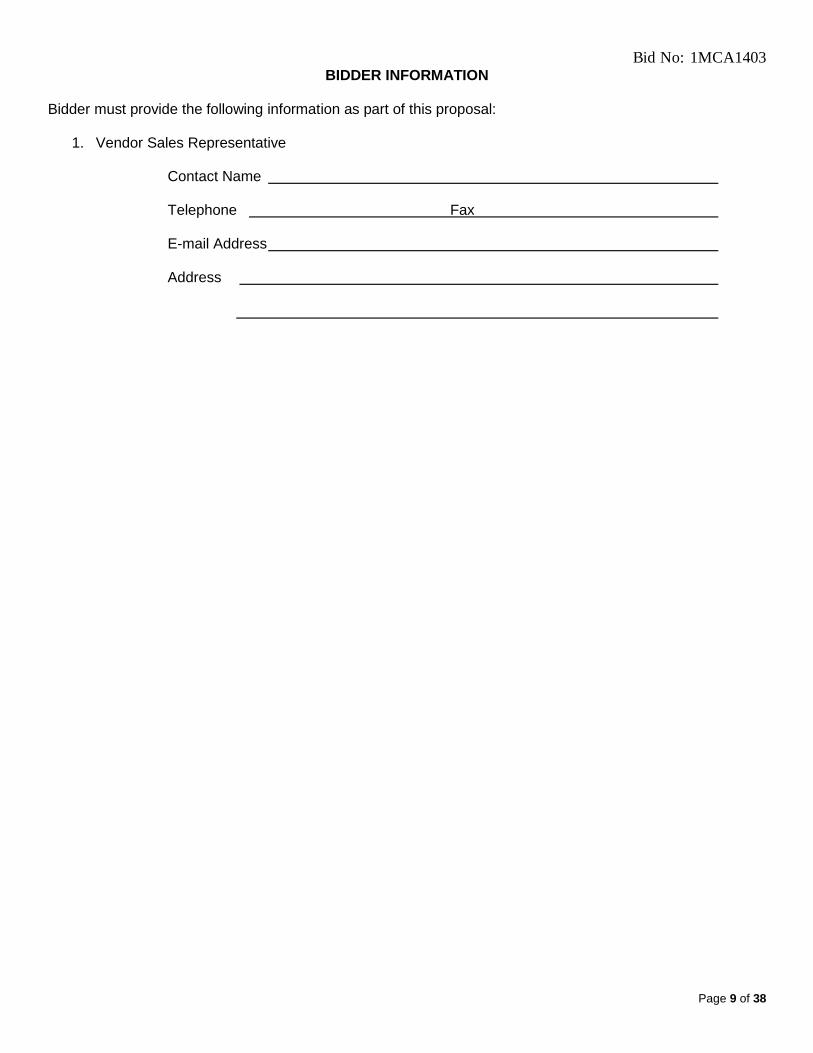
BIDDER INFORMATION Bidder must provide the following information as part of this proposal:
1. Vendor Sales Representative
Contact Name Telephone Fax E-mail Address Address

Bid No: 1MCA1403
Page 10 of 38
SPECIAL TERMS AND CONDITIONS
WARRANTY AND SERVICE INFORMATION The information provided below must be completed and accurate and may be used in evaluating the offers received. WARRANTY: (To be completed by vendor)
LENGTH OF WARRANTY
__________________ months labor __________________ months parts __________________ months travel
COVERAGE:
List any exclusions or limitations that apply to your warranty (e.g., expendables [give details], on call hours, etc.)
________________________________________________________________________ ________________________________________________________________________ ________________________________________________________________________ ________________________________________________________________________ EXTENDED WARRANTY:
Is extended warranty available on the equipment offered? ____________ Yes ____________ No If Yes, indicate the current cost for the following duration(s) of warranty extension: $_________________ 12 month warranty extension $_________________ 24 month warranty extension

Bid No: 1MCA1403
Page 11 of 38
Service Information Sheet: List the average response time for service: If call is received prior to 12:00 p.m. If call is received after 12:01 p.m. Hours of available service on weekends and evenings Hourly cost of service weekdays during normal working hours Is there a premium charge for after hours: Yes_______ No_______ Charge______ Is there a charge for mileage: Yes_______ No_______ Charge______ Is there a hourly charge for travel time: Yes_______ No_______ Charge______ Is travel time charged: To only: Yes_______ No _______ To and from: Yes_______ No _______ Is there a premium charge for Saturday: Yes_______ No_______ Charge______ Is there a premium charge for Sunday: Yes_______ No_______ Charge______ Is there a premium charge for Holidays: Yes_______ No_______ Charge______ List Holidays charge applies to: When a service engineer is brought in for consultation with the local engineer regarding a service problem, from what location is time and travel charged?
_______________________________________________ During warranty service what is the charge for after hours, Saturday, Sunday and Holiday:
_______________________________________________ List percentage of parts, that are critical for normal operation of the equipment, that are not available from local service center and would take more than one full day to receive from another area to fix equipment.
%___________________ What parts are carried by your service personnel i.e., transistors, tubes, switches, fuses, bulbs, etc.
_______________________________________________

Bid No: 1MCA1403
Page 12 of 38
GENERAL TERMS AND CONDITIONS
1. Standard Qualifications, Certifications, Representations, and Disclosures Attachment: The
respondent must complete, sign where appropriate, and return the enclosed "Standard Qualifications, Certifications, Representations, and Disclosures Attachment (Exhibits A, B, & C)”. Please attach Exhibits A, B, & C to your offer. In the event that further clarification is required on any of the information provided, the University reserves the right to make any necessary communication with a respondent for such purpose. Such communication, if made, may include a deadline by which time any necessary clarifying information must be submitted.
2. State of Illinois Business Entity Registration: Companies are required to register with the State of Illinois, including the Illinois Secretary of State and Illinois Department of Revenue, to comply with various required reporting obligations. It is critical that you complete this registration prior to submitting your proposal. Information regarding registration and associated fees may be found at http://business.illinois.gov/default.cfm.
3. Illinois Department of Human Rights Number: All respondents must register for an eligible bidder number through the Illinois Department of Human Rights (DHR) by filing an Employer Report Form (PC-1) with the DHR Public Contracts unit. All proposals require this number or a statement by the respondent that a PC-1 Employer Report Form has been submitted to the DHR prior to the Bid due date for the respondent to be eligible to propose an offer for this contract. The Employer Report form is available at http://www.state.il.us/dhr/Programs/DHR_PBCT.htm. Include the DHR number in Taxpayer Identification and Certifications and Conflicts.
Note: DHR numbers are valid for five years from the date of issuance. If a Proposer’s DHR number was issued in excess of the five years, the proposer is required to renew their number with the DHR Public Contracts unit.
In the event of the contractor's non-compliance with the provisions of this Equal Employment Opportunity Clause, the Illinois Human Rights Act or the Rules and Regulations of the Illinois Department of Human Rights ("Department"), the contractor may be declared ineligible for future contracts or subcontracts with the State of Illinois or any of its political subdivisions or municipal corporations, and the contract may be canceled or voided in whole or in part, and such other sanctions or penalties may be imposed or remedies invoked as provided by statute or regulation
For more information, contact the DHR, Public Contracts Unit, Suite 10-100, 100 West Randolph Street, Chicago, Illinois 60601, (312) 814-2431, or see the following Web Sites: http://www.state.il.us/dhr/Programs/DHR_PBCT.htm.
4. Procurement Rules: All bidding, proposals, offers and procurement will be conducted in accordance
with the Procurement Rules of the Chief Procurement Officer for Public Institutions of Higher Education, which have been adopted pursuant to the Illinois Procurement Code. All respondents will be strictly held to these statutes and rules and they are considered incorporated herein by reference as if attached hereto. The Respondent remains solely responsible for insuring that its Proposal is received at the time, date, place, and office specified.
5. University Form: Please use our solicitation form for submitting your offer. If you do not comply, we
may reject your offer as “non-responsive.”
6. Exceptions: The University discourages taking exceptions. Any exceptions taken may result in rejection of the bid/proposal, and exceptions that would violate the Procurement Code, the rules adopted thereunder (including rules on rejection due to failure to meet acceptability requirements), or other law shall

Bid No: 1MCA1403
Page 13 of 38
result in rejection. Any exceptions to the University’s language or requirements must be provided on the ”Exceptions and/or Alternate Offer” section above.
7. Signatures: This solicitation should be signed in any space provided in this solicitation by an authorized official of the respondents' organization.
8. Offer Acceptance: All responses should be firm for acceptance for a period of 90 days. 9. Contacts: Questions regarding bidding, proposals or procedures should be addressed to 10. Specifications: Any reference to brand names and numbers in the solicitation is descriptive, but not
restrictive, unless otherwise specified. Offers on equivalent items meeting the standards of quality thereby indicated will be considered, unless otherwise specified, providing the offer clearly describes the article offered and how it differs from the referenced brands. Unless the respondent specified otherwise, it is understood that the respondent is offering a referenced brand item as specified in the solicitation. The University will determine whether a substitute offer is equivalent to and meets the standards of quality indicated by the brand name referenced; and the University may require a respondent offering a substitute to supply additional descriptive material and a sample.
If Items requested have quality guidelines of brand name or equal, the items offered must be equal to or better than the brands and model numbers specified as determined by the University of Illinois. The use of brand names in this solicitation are for the purpose of describing the standard of quality, performance and characteristics desired and is not intended to limit or restrict competition. Substantially equivalent products to those designated may be considered for award. “Or Equal” submissions will not be rejected because of minor differences in design, construction or features that do not affect the suitability of the product for its intended use.
11. Samples: If requested, samples of items must be furnished free of charge and if not destroyed will,
upon request, be returned at the respondents expense. Request for the return of samples must be made within ten (10) days following opening of Bid or RFP or submittal of samples, whichever is later. Each individual sample must be labeled with respondents' name, manufacturer's brand name and product number, bid or RFP number and item referenced. The University reserves the right to keep the samples of the low respondent. Failure to submit samples when requested will be considered grounds for rejection of your offer. DO NOT submit samples unless you are specifically requested to do so. Samples should arrive within 7 working days from receipt of request.
12. Clarifications: Should any respondent have questions concerning conditions and specifications, or find
discrepancies in or omissions from the specifications, or be in doubt as to their meaning, they should notify the Purchasing Division no later than five (5) days prior to the opening and obtain clarification prior to submitting a solicitation. Such inquires must reference the date of opening and University bid or RFP number.
Interpretations that change the terms, conditions, or specifications will be made in the form of an amendment to the solicitation by the University. If issued, the University will send the amendment to all parties solicited in the original solicitation. In the event there are any conflicts between the general terms and conditions and any special terms and conditions, the special terms and conditions shall take precedence.
13. Quality: It is the intention of the University of Illinois to purchase high quality material and/or services and evaluation of responses will be made on this basis.
14. Product Documentation: Furnish with your response, descriptive literature, including manufacturer's
specifications, performance, other operational capabilities and contents if applicable.
Bid No: 1MCA1403
Page 14 of 38
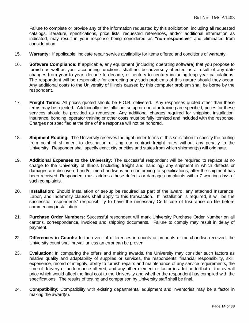
Failure to complete or provide any of the information requested by this solicitation, including all requested catalogs, literature, specifications, price lists, requested references, and/or additional information as indicated, may result in your response being considered as "non-responsive" and eliminated from consideration.
15. Warranty: If applicable, indicate repair service availability for items offered and conditions of warranty. 16. Software Compliance: If applicable, any equipment (including operating software) that you propose to
furnish as well as your accounting functions, shall not be adversely affected as a result of any date changes from year to year, decade to decade, or century to century including leap year calculations. The respondent will be responsible for correcting any such problems of this nature should they occur. Any additional costs to the University of Illinois caused by this computer problem shall be borne by the respondent.
17. Freight Terms: All prices quoted should be F.O.B. delivered. Any responses quoted other than these terms may be rejected. Additionally if installation, setup or operator training are specified, prices for these services should be provided as requested. Any additional charges required for shipping, installation, insurance, bonding, operator training or other costs must be fully itemized and included with the response. Charges not specified at the time of the response will not be honored.
18. Shipment Routing: The University reserves the right under terms of this solicitation to specify the routing from point of shipment to destination utilizing our contract freight rates without any penalty to the University. Responder shall specify exact city or cities and states from which shipment(s) will originate.
19. Additional Expenses to the University: The successful respondent will be required to replace at no
charge to the University of Illinois (including freight and handling) any shipment in which defects or damages are discovered and/or merchandise is non-conforming to specifications, after the shipment has been received. Respondent must address these defects or damage complaints within 7 working days of such complaints.
20. Installation: Should installation or set-up be required as part of the award, any attached Insurance,
Labor, and Indemnity clauses shall apply to this transaction. If installation is required, it will be the successful respondents' responsibility to have the necessary Certificate of Insurance on file before commencing installation.
21. Purchase Order Numbers: Successful respondent will mark University Purchase Order Number on all
cartons, correspondence, invoices and shipping documents. Failure to comply may result in delay of payment.
22. Differences in Counts: In the event of differences in counts or amounts of merchandise received, the
University count shall prevail unless an error can be proven. 23. Evaluation: In comparing the offers and making awards, the University may consider such factors as
relative quality and adaptability of supplies or services, the respondents' financial responsibility, skill, experience, record of integrity, ability to furnish repairs and maintenance of any service requirements, the time of delivery or performance offered, and any other element or factor in addition to that of the overall price which would affect the final cost to the University and whether the respondent has complied with the specifications. The results of testing and comparison by University staff shall be final.
24. Compatibility: Compatibility with existing departmental equipment and inventories may be a factor in
making the award(s).

Bid No: 1MCA1403
Page 15 of 38
25. Delivery Schedule: Time is of the essence and delivery schedules may be considered in the overall analysis.
26. Pricing: All price and cost information requested in this solicitation should be provided by the respondent.
While price is usually a primary factor in the evaluation of responses received, the relevant importance of price may vary based on the nature of the purchase and the related significance of other criteria as may be expressed elsewhere in this solicitation. In evaluating price, the University may give consideration to all cost factors relevant to determine the total final cost to the University, including but not limited to: life cycle cost, cost of replacing existing inventory, and administrative cost of issuing multiple awards. The University will be the sole determinant of the relevant and appropriate cost factors to be used in evaluating any Base or Alternate offers and/or Options.
27. Awards: The University may, at its discretion evaluate all offers submitted on the basis of any Base or
Alternate offers and/or Options indicated in this solicitation. If offers on trade-in equipment are requested, the University reserves the right to evaluate and award with or without trade-in, whichever is in the best interest of the University. If trade-in equipment is part of this transaction, the vendor is responsible for removal of trade-in equipment including dismantling, crating, cartage, and/or shipping related costs unless otherwise indicated.
28. Split Awards: Unless otherwise stated in this solicitation, the University makes every attempt to award orders on an overall basis to the lowest responsible respondent meeting the specifications, terms and conditions. However, the right is reserved to make separate awards. If a split award is not acceptable to a respondent, it must be so stated in the response.
29. University Rights: The University reserves the right to reject any and all offers, to waive any informality in the offers and, unless otherwise specified by the vendor, to accept any item in the offer. The University also reserves the right to accept or reject all or part of your offer, in any combination that is economically advantageous to the University of Illinois.
30. Subcontracting: Any contract or purchase order arising from this solicitation shall not be assigned or
sublet in whole or in part without the written consent of the University of Illinois. 31. Cancellation for cause: Any purchase agreement or contract arising from this solicitation will be subject
to cancellation by the University of Illinois upon written notice and without penalty to the University of Illinois if, in the opinion of the University of Illinois, the quality, delivery schedule, specifications, terms, conditions, and other service requirements are not maintained as originally stated and accepted by the vendor.
32. Multiple Year Contracts: If the initial term of the contract spans multiple fiscal years (July 1 through June
30) the following funding clause is applicable. Any purchase agreement or contract arising from this solicitation is subject to termination and cancellation in any year for which the General Assembly fails to make an appropriation to make payments under the terms of the purchase agreement contract.
33. Federal Funding: In the event that Federal funds are used for any purchase arising from this
solicitation, the “FEDERAL SUBCONTRACT/PURCHASE ORDER FLOWDOWN PROVISIONS” if attached apply to this transaction and will apply to any subsequent purchase order.
The resulting contract may be partially or totally funded with Federal Funds. Upon notice of intent to award, the percentage of the good/service involved which is federally funded and the dollar amount of such Federal funds will be disclosed and provided as an amendment to the contract.
34. Taxes: Sales to the University, unless otherwise stated, are exempt from Illinois R.O.T. and Federal
Taxes. The University of Illinois tax exempt number is E9989-9779-04.

Bid No: 1MCA1403
Page 16 of 38
The University is an instrumentality of the State of Illinois, and as such it is exempt from Federal Income Tax under Sections 115 and 501(c)(3) of the Internal Revenue Code and is exempt from State of Illinois Income Tax in accordance with the Illinois Income Tax Act (35 ILCS 5/205). However, the University is subject to Federal and State of Illinois Income Tax only if, and to the extent, it has unrelated business taxable income. In addition, the University is exempt from payment of state and local Retailers' Occupation Tax, state and local Service Occupation Tax, state Use Tax, and state Service Use Tax, as provided by Illinois law. Certificates of exemption will be provided upon written request.
36. Procurement Card: Does respondent accept Procurement Cards (Master Card). Yes ____ No _____. 37. Payment Terms: Payment(s) in relation to any award for this proposal are subject to the State Prompt
Payment Act (30 ILCS 540). Prompt payment discounts, of less than 30 days, will not be considered for evaluation purposes, however, applicable discount(s) will be taken if processed within the stated time limit.
38. State Preference Percentage: If respondent is an out-of-state vendor (not having an establishment for transacting business within Illinois), and if respondent’s state has a preference law favoring in-state vendors, what is the percentage preference? ___________ %
39. Recycling: Packaging which is readily recyclable, made with recyclable materials, and designed to minimize potential adverse effects on the environment when disposed of by incineration or in a landfill is desired to the extent possible. Product(s) offered which contain recycled materials may be acceptable provided they meet all pertinent specifications and performance criteria outlined in this proposal. If the product(s) offered are manufactured utilizing recycled materials, identify the percentage composition and nature of the recycled content:
40. Alteration/Modification of Original Documents: The contractor certifies that no alterations or modifications may be made to the original content of this Bid/RFP or other procurement documents (either text or graphics and whether transmitted electronically or hard copy). Any alternates or exceptions (whether to products, services, terms, conditions, or other procurement document subject matter) are apparent and clearly noted in the offered response. Contractor understands that failure to comply with this requirement may result in the offer being disqualified and, if determined to be a deliberate attempt to misrepresent the offer, may be considered as sufficient basis to suspend or debar the violating party from consideration for future contract awards.
41. Protest Review Office: Vendors may submit a written protest to the Protest Review Office following the requirements of the Higher Education Standard Procurement Rules 44 ILL. ADMIN. CODE 4.5550. For protests related to specifications, the Protest Review Office must physically receive the protest no later than 14 days after the solicitation or related addendum was posted to the Bulletin. For protests related to rejection of individual proposals or awards, the protest must be received by close of business no later than 14 days after the protesting party knows or should have known of the facts giving rise to the protest. The Protest Review Office’s information is as follows:
Chief Procurement Office Phone: (217) 558-3724 Attn: Protest Review Office Facsimile: (217) 558-2164 Suite 513 Stratton Office Building
401 South Spring Street Illinois Relay: (800) 526-0844 Springfield, IL 62706

Bid No: 1MCA1403
Page 17 of 38
If the protest is submitted via email, it must be sent to both of the following email addresses:

Bid No: 1MCA1403
Page 18 of 38
COMPLIANCE WITH LAWS, REGULATIONS AND LABOR AND EMPLOYMENT PROVISIONS:
The Contractor agrees to comply with all laws, statutes, regulations, ordinances, rulings, or enactments of
any governmental authority that are applicable to the work or which in any way pertain to the project
including, without limiting the foregoing thereto, the following State of Illinois statutes:
a. “An Act concerning Construction contracts; responsible bidder requirements (30 ILCS 500/30-22). To be
considered a responsible bidder on a construction contract for purposes of this Code, a bidder must comply with all of the following requirements and must present satisfactory evidence of that compliance to the appropriate construction agency: (1)The bidder must comply with all applicable laws concerning the bidder's entitlement to conduct business in Illinois. (2) The bidder must comply with all applicable provisions of the Prevailing Wage Act. (3) The bidder must comply with Subchapter VI ("Equal Employment Opportunities") of Chapter 21 of
Title 42 of the United States Code (42 U.S.C. 2000e and following) and with Federal Executive Order No. 11246 as amended by Executive Order No. 11375.
(4) The bidder must have a valid Federal Employer Identification Number or, if an individual, a valid Social Security Number.
(5) The bidder must have a valid certificate of insurance showing the following coverages: general liability, professional liability, product liability, workers' compensation, completed operations, hazardous occupation, and automobile.
(6) The bidder and all bidder's subcontractors must participate in applicable apprenticeship and training programs approved by and registered with the United States Department of Labor's Bureau of Apprenticeship and Training.
The provisions of this Section shall not apply to federally funded construction projects if such application would jeopardize the receipt or use of federal funds in support of such a project.
(Source: P.A. 93-642, eff. 6-1-04.)
b. "AN Act concerning the distribution of certain federal grants and the employment of Illinois workers" (30
ILCS 570). The Act requires the employment of only Illinois laborers on all public works projects or improvements or for the clean-up and on-site disposal of hazardous waste whenever there is a period of excessive unemployment in Illinois, except when qualified Illinois laborers are unavailable or incapable of performing the particular type of work involved. The term "Illinois Laborer" is defined as any person who has resided in Illinois for at least 30 days and intends to become or remain an Illinois resident. The term "labor" is defined to include all manual or nonmanual labor, whether skilled, semiskilled or unskilled. An exception to the above requirement is permitted by the statute in that the Contractor may place up to three of his regularly employed non-resident executive and technical experts on the job (six in some specific instances), even though they do not qualify as Illinois laborers.
c. "AN Act to give preference to veterans of the United States military and naval service in appointments and
employment upon public works by, or for the use of, the State or its political subdivision" (330 ILCS 55). This Act requires that preference in employment on public works to be given qualified veterans of wartime military or naval service who were honorably discharged therefrom, including persons on inactive or reserve duty, who are residents of the district where the work is to be done. It is not required that nonresident veterans be given preference over nonveteran residents.
d. "AN Act to prohibit discrimination and intimidation on account of race, creed, color, sex, religion, physical or
mental handicap unrelated to ability or national origin in employment under contracts for public buildings or public works" (755 ILCS 10). This Act requires that no person may be refused or denied employment in any capacity on the ground of unlawful discrimination, as that term is defined in the Illinois Human Rights Act, nor be subjected to unlawful discrimination in any manner in connection with the contracting for or the performance of any work or service of any kind, by, on behalf of, or for the benefit of this State, or of any department, bureau, commission, board, or other political subdivision or agency thereof and that no

Bid No: 1MCA1403
Page 19 of 38
contractor, subcontractor or person on behalf of either shall discriminate against or intimidate any employee for such reason, and provides penalties and recoveries for violation of its provisions.
e. The Illinois Human Rights Act (775 ILCS 5). The purpose of this Act is to secure for all individuals within
Illinois the freedom from sexual harassment, from discrimination because of race, color, religion, sex, national origin, ancestry, age, marital status, physical or mental handicap, or unfavorable discharge from military service in connection with employment, real estate transaction, access to financial credit, and the availability of public accommodations. The Illinois Department of Human Rights and the Illinois Human Rights Commission are assigned duties for the enforcement of the Act. Violation of the Act might result in penalties, including the payment of damages, termination of public contract or prohibition from participating in public contracts for up to three years.
f. "AN Act regulating wages of laborers, mechanics and other workmen employees in any public works by
the State, county, city or any public body or any political subdivision or by any one under contract for public works" (8201 ILCS 130). This Act requires that wages not less than the general prevailing rate of hourly wages for work of a similar character in the locality in which the work is performed, and not less than the general prevailing rate of hourly wages for legal holiday and overtime work in that locality shall be paid to all laborers, workmen and mechanics employed on the work (a determination of the prevailing rates for all crafts is, as required by the Act, on file at the University of Illinois Personnel Services Office, Gregory Drive, Champaign, Illinois). It is further required by the Act and by these General Conditions that the Contractor and each of his subcontractors shall keep, or cause to be kept, an accurate record showing the names and occupation of all laborers, workmen and mechanics employed by them in connection with the work, and showing also the actual hourly wages paid to each of such workers, which record shall be open at all reasonable hours to the inspection of the Owner, its officers and agents and to the Director of the Department of Labor of the State of Illinois and his deputies and agents. "Prevailing rate of wages" mean the hourly cash wages, plus fringe benefits for health and welfare, insurance, vacations and pensions paid generally, in the locality in which the work is being performed, to employees engaged in work of similar character.
"NOTE: The above labor clauses apply to all trade labor employed in the installation of purchased goods
on University property and includes the unloading of trucks and other service vehicles if required as part of the contract (award)."
g. "AN Act relating to the health and safety of persons employed, vesting in the industrial commission power
to make reasonable rules relating thereto; providing for the enforcement thereof; and repealing certain acts herein named (820 ILC0S 225/01/5). This Act makes it the duty of every employer under the Act to provide reasonable protection to the life, health and safety and to furnish to each of his employees employment and a place of employment which are free from recognized hazards that are causing or are likely to cause death or serious physical harm to these employees and requires that occupational safety and health standards be complied with.
The above explanations of these Acts are much condensed and not intended to be a complete detailed account of all duties imposed thereby, and hence by these General Conditions, upon the Contractor. The Contractor agrees to, and shall comply with all of the provisions of the above Acts, whether herein set forth or not, as well as with the provisions of all other applicable legislation and regulations promulgated thereunder, and especially agrees to keep the records described in paragraph (e) and pay the prevailing rate of hourly wages as required. The Contractor shall carry insurance to cover any injuries to his employees or damage to University property. FN-88 (06/05)

Bid No: 1MCA1403
Page 20 of 38
INDEMNITY AGREEMENT AND LIABILITY INSURANCE: The Contractor shall indemnify and hold harmless the Owner and Owner's agents, servants and employees against all loss, damage and expense which they may sustain or become liable for on account of injury to or death of persons, or on account of damage to or destruction of property resulting from the performance of work under the Contract by the Contractor or his Subcontractors or due to or arising in any manner from the wrongful act or negligence of the Contractor or his Subcontractors or any employee of any of them. If required under the terms of award or if work on any University property is to be performed by the Vendor/Contractor, the Vendor/Contractor receiving the award shall cause a Certificate of Insurance to be issued showing the following required coverage in no less than the minimum coverage limits listed below. The insurance companies providing coverage must have a B+:VI or better rating in the current edition of Best’s Key Rating Guide. The Vendor/Contractor must agree to maintain such insurance for the duration of the project or the term for which services will be rendered.
A. Worker’s Compensation (including Occupational Disease) - Statutory Limits Employer’s Liability (Part B) - $500,000 Policy Limit
B. Commercial General Liability
(including Products & Completed Operations) Combined Single Limit - $1,000,000 per occurrence OR Bodily Injury: $1,000,000 per occurrence, and Property Damage: $1,000,000 per occurrence
C. Commercial Automobile Liability
Combined Single Limit - $1,000,000 per occurrence OR
Bodily Injury: $1,000,000 per occurrence, and Property Damage: $1,000,000 per occurrence
Assigned subcontractors must comply with the same insurance coverage requirements as the Vendor/Contractor. Subcontractors shall submit the required Certificate of Insurance through the primary Vendor/Contractor. With respect to the required Commercial General Liability insurance, The Board of Trustees of the University of Illinois shall be named as an additional insured. In order to meet this requirement, the following wording should appear on any Certificate of Insurance provided: "The Board of Trustees of the University of Illinois is an additional insured for any liability incurred by the University arising from the activities of the Vendor/Contractor and/or Subcontractor performing work on behalf of the Vendor/Contractor." Umbrella liability insurance may be used to meet the general liability coverage limit requirements.

Bid No: 1MCA1403
Page 21 of 38
INDEMNITY AGREEMENT AND LIABILITY INSURANCE (Continued): The Vendor/Contractor shall furnish the University of Illinois, Purchasing Division, Illini Plaza, Suite 212, 1817 South Neil Street, Champaign, IL 61820 any original Certificate(s) of Insurance evidencing the required coverage to be in force on the date of this agreement, and any renewal Certificate(s) of Insurance if coverage has an expiration or renewal date occurring during the term of this agreement. The receipt of any certificate does not constitute agreement by the University that insurance requirements have been met. Failure of the University to obtain certificates or other insurance evidence from the vendor/contractor shall not be deemed a waiver by the University. Failure to comply with insurance requirements may be regarded as a breach of contract terms. Any Purchase Order Number and/or Contract Number that is the basis for issuance of the Certificate must be indicated on the Certificate of Insurance provided to the University. *****************
Bid No: 1MCA1403
Page 22 of 38
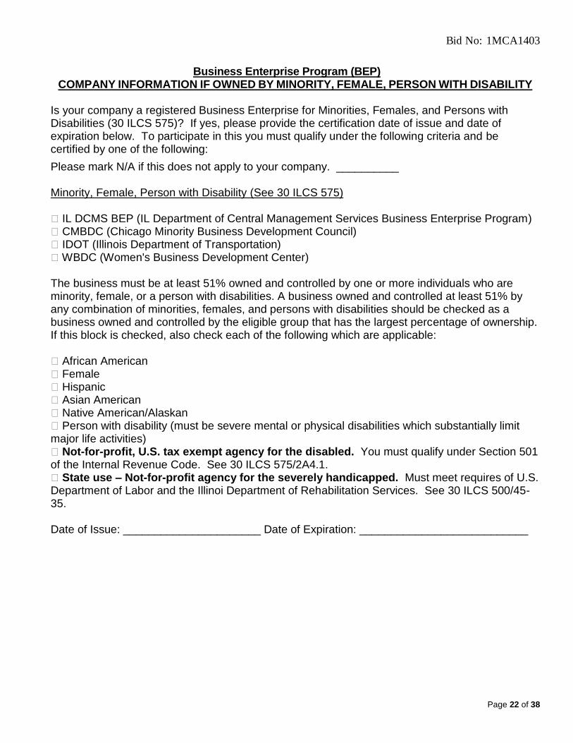
Business Enterprise Program (BEP)
COMPANY INFORMATION IF OWNED BY MINORITY, FEMALE, PERSON WITH DISABILITY
Is your company a registered Business Enterprise for Minorities, Females, and Persons with Disabilities (30 ILCS 575)? If yes, please provide the certification date of issue and date of expiration below. To participate in this you must qualify under the following criteria and be certified by one of the following:
Please mark N/A if this does not apply to your company. __________ Minority, Female, Person with Disability (See 30 ILCS 575) � IL DCMS BEP (IL Department of Central Management Services Business Enterprise Program) � CMBDC (Chicago Minority Business Development Council) � IDOT (Illinois Department of Transportation) � WBDC (Women's Business Development Center) The business must be at least 51% owned and controlled by one or more individuals who are minority, female, or a person with disabilities. A business owned and controlled at least 51% by any combination of minorities, females, and persons with disabilities should be checked as a business owned and controlled by the eligible group that has the largest percentage of ownership. If this block is checked, also check each of the following which are applicable: � African American � Female � Hispanic � Asian American � Native American/Alaskan � Person with disability (must be severe mental or physical disabilities which substantially limit major life activities) � Not-for-profit, U.S. tax exempt agency for the disabled. You must qualify under Section 501 of the Internal Revenue Code. See 30 ILCS 575/2A4.1. � State use – Not-for-profit agency for the severely handicapped. Must meet requires of U.S. Department of Labor and the Illinoi Department of Rehabilitation Services. See 30 ILCS 500/45-35. Date of Issue: ______________________ Date of Expiration: ___________________________

Bid No: 1MCA1403
Page 23 of 38
ADDITIONAL REQUIREMENTS AND CERTIFICATIONS Standard Qualifications, Certifications, Representations, and Disclosures Attachment: Contractor shall confirm compliance with the Standard Qualifications, Certifications, Representations, and Disclosures attached as Exhibits A, B, & C, which is hereby incorporated into this solicitation by reference. Taxpayer Identification Certification: The Internal Revenue Service requires that the University request the following certification. See instructions below for completing the certification. Under penalties of perjury, I certify that no. is my correct Federal Taxpayer Identification Number. I am doing business as a (check one): Individual Real Estate Agent Sole Proprietorship Governmental Entity Partnership Tax Exempt Organization IRC 501(a) only Corporation Trust or Estate Not-for-profit Corporation Services Provider Corporation Medical and Health Care Signature_______________________________ Date_______________________________ Instructions: Enter your Taxpayer Identification Number (TIN) in the appropriate space. For individuals and sole proprietors, this is your Social Security Number. For other entities, it is your employer identification number. Federal Employer Identification Numbers (FEIN's) must not be used for sole proprietorships. If you do not have a TIN, apply for one immediately. To apply, get Form SS-5, Application for Social Security Number Card (for individuals) from your local office of the Social Security Administration, or Form SS-4, Application for Employer Identification Number (for businesses and all other entities), from your local Internal Revenue Service office. To complete the certification if you do not have a TIN, fill out the certification indicating that TIN has been applied for, sign and date the form, and return it to the University. As soon as you receive your TIN, fill out another such form including your TIN, sign and date the form, and return it to the University. If you fail to furnish your correct TIN to this agency, you are subject to an IRS penalty of $50.00 for each such failure unless your failure is due to reasonable cause and not to willful neglect. Willfully falsifying TIN related certifications or affirmations may subject you to criminal penalties including fines and/or imprisonment. Contact Information: Respondent's phone number to place orders: 800- If no 800 number: FAX number: Sales representative's e-mail:

Bid No: 1MCA1403
Page 24 of 38
(if needed) COMBINED PAYMENT AND PERFORMANCE BOND
UNIVERSITY OF ILLINOIS AT URBANA\CHAMPAIGN, ILLINOIS We,______________________________________________________________________________________ _____________________________, as Principal, and______________________________________________ _________________________________________________________________________________________ a corporation organized as existing under the laws of the State of ______________, and duly authorized to transact business in the State of Illinois, as Surety,(hereinafter referred to as Surety) are held firmly bound unto The Board of Trustees of the University of Illinois (hereafter referred to as University) in the sum of______________________ Dollars ($___________________) lawful money of the United States, well and truly to be paid unto said University for the payment of which we bind ourselves, our heirs, executors, administrators, successors and assigns jointly and severally, to pay to the University this sum under the conditions of this instrument. WHEREAS THE CONDITION OF THE FOREGOING OBLIGATION IS SUCH that the said Principal has entered into a written contract with the University for the completion of work on the contract to which this is attached, which contract is hereby referred to and made a part hereof, as if written herein at length, and whereby the said Principal has promised and agreed to perform said work in accordance with the terms of said contract, and has promised to pay all sums of money due, defend, indemnify and hold harmless the University from all claims, demands, liens or suits by any person or entity who furnished any labor, services, materials, apparatus, fixtures or machinery furnished to such Principal for the purpose of performing such work and has further agreed to pay all direct and indirect damages to any person, firm, company, or corporation suffered or sustained on account of the performance of such work during the time thereof and until such work is completed and accepted and any warranty period applicable thereto completed; and has further agreed that this bond shall inure to the benefit of any person, firm, company, or corporation, to whom any money may be due from the Principal, subcontractor or otherwise, for any such labor, services, materials, apparatus, fixtures or machinery so furnished and that suit may be maintained on such Bond by any such person, firm, company, or corporation, for the recovery of any such money; provided however, that the University shall have first priority on all funds to make themselves whole as to the original consideration of the contract. Residual funds, if any, will then be distributed to third party claimants to the amount remaining. NOW, THEREFORE, if the said Principal shall well and truly perform said work in accordance with the terms of said contract, and shall pay all sums of money due or to become due, defends, indemnifies and holds harmless the University from all claims demands, liens or suits by any person or entity who furnished any labor, services, materials, apparatus, fixtures or machinery furnished to the Principal for the purpose of completing such work, and shall commence and complete the work within the time prescribed in said contract, and shall pay and discharge all damages, direct and indirect, that may be suffered or sustained on account of such work during the time of the performance thereof and until the said work shall have been accepted, and any warranty period applicable thereto completed, and shall hold the University and its employees and agents as required in said Contract on account of any such damages and shall in all respects fully and faithfully comply with all the provisions, conditions and requirements of said contract, then this obligation to be void; otherwise to remain in full force and effect and upon notice to the Surety of the Principal's failure to perform, the Surety shall perform the obligations of the Principal hereunder. The University may request payment on this Bond from the Surety or may sue on this Bond for breach of any contract terms, and any person furnishing material or performing labor, either as an individual or as a Subcontractor, shall have the right to sue on this Bond in the name of the University for its use and benefit.

Bid No: 1MCA1403
Page 25 of 38
The said Surety, for value received, hereby stipulates and agrees that no change, extension of time, alteration or addition to the terms of the Contract or the Contract Documents accompanying the same or to the Work to be performed thereunder shall in any way affect its obligations on this Bond, and it does hereby waive notice of any such change, extension of time, alteration or addition to the terms of the Contract or to the Work or to the Contract Documents. PROVIDED, FURTHER, that no final settlement between the University and the Contractor shall abridge the right of any beneficiary hereunder, whose claim may be unsatisfied. In addition, the Principal and Surety, their heirs, executors, administrators, successors, and assigns, jointly and severally, expressly guarantee that all services to be performed, all materials to be furnished, and all performance under the Contract shall be fulfilled in accordance with all requirements of the Contract and the Contract Documents. In addition, Principal and Surety, their heirs, executors, administrators, successors, and assigns, jointly and severally, expressly guarantee that in the event University is required to enforce this Bond in a court of law, University will be indemnified with respect to all court costs and reasonable attorneys' and witness fees which are related to such enforcement proceedings. The Surety hereby waives notice of any alteration or extension of time made by the University. Whenever Contractor shall be, declared by the University to be in default under the Contract, the University having performed its obligations thereunder, the Surety may promptly remedy the default, or shall promptly: Complete the Contract in accordance with its terms and conditions, or
Obtain a bid or bids from qualified bidders acceptable to the University for a contract for performance and completion of the Contract, arrange for a contract to be prepared for execution by the University and the bidder selected with the University's concurrence, to be secured with a combined payment and performance bond executed by a qualified surety equivalent to the Bond issued on the Contract, and make available as Work progresses sufficient funds to pay the cost of completion and the cost and damages for which the Surety may be liable hereunder in excess of the Balance of the Contract.
Any suit under this bond must be instituted before the expiration of two (2) years from the date on which final payment under the Contract falls due.

Bid No: 1MCA1403
Page 26 of 38
IN TESTIMONY WHEREOF, the said Principal and the said Surety have caused this instrument to be signed by their respective officers and their corporate seals to be hereunto affixed this __________day of _________, A.D. 20___. In The Presence of: WITNESS INDIVIDUAL PRINCIPAL 1. as to (Seal) 2. as to (Seal) 3. as to (Seal) 4. as to (Seal) Attest: Corporate Principal
Name
Title
Business Address Affix Corporate Seal
Corporate Surety
Name
By
Business Address Affix Corporate Seal
_________________________________________________________________________________________ University of Illinois Acceptance Approvals: Supervisor of Insurance____________________ _______________ Approved Date Legal Counsel ____________________ _______________
Approved Date

Bid No: 1MCA1403
Page 27 of 38
EXHIBIT A. CERTIFICATIONS
By executing the Contract Vendor certifies it is under no legal prohibition on contracting with the State of Illinois, has no known conflicts of interest and further specifically certifies that: 1. Vendor, its employees and subcontractors will comply with applicable provisions of the U.S. Civil Rights Act, Section 504 of the Federal Rehabilitation
Act, the Americans with Disabilities Act (42 U.S.C. § 12101 et seq.) and applicable rules in performance under this Contract. 2. This applies to individuals, sole proprietorships, partnerships and LLCs, but is not otherwise applicable . Vendor is not in
default on an educational loan (5 ILCS 385/3).
3. Vendor is an existing legal entity, and as applicable: has obtained an assumed name certificate from the appropriate authority, is registered to conduct business in Illinois, and is in good standing with the Illinois Secretary of State (30 ILCS 500/1.15.80).
4. This applies only to certain service contracts and does NOT include contracts for professional or artistic services. . If this is a service
contract as defined in 30 ILCS 500/25-80, Vendor (i) will offer to assume the collective bargaining obligations of the prior employer, including any existing collective bargaining agreement with the bargaining representative of any existing collective bargaining unit or units performing substantially similar work to the services covered by the Contract subject to its bid or offer, and (ii) shall offer employment to all employees currently employed in any existing bargaining unit performing substantially similar work that will be performed under this Contract). This certification does not apply to heating and air-conditioning, plumbing and electrical service contracts. If this Contract includes janitorial, window cleaning, building and grounds, site technical, natural resource, security, or food services amounting to $2,000 or more (or $200 or more per month), Vendor shall pay its employees who are to provide the services the prevailing wage rate and provide working conditions no less favorable than those prevalent in the locality where the Contract is to be performed (30 ILCS 500/25-60).
5. If this Contract includes printing services in any amount, Vendor shall pay its employees who are to provide the printing services the prevailing
wage rate and provide working conditions no less favorable than those prevalent in the locality where the Contract is to be performed (30 ILCS 500/25-60). Unless otherwise indicated in the Contract documentation, any printing services provided shall be made using soybean oil-based ink (30 ILCS 500/45-15).
6. Vendor has not been convicted of bribing or attempting to bribe an officer or employee of the State of Illinois or any other State, nor has Vendor made
an admission of guilt of such conduct that is a matter of record (30 ILCS 500/50-5). 7. If Vendor has been convicted of a felony, at least five years have passed after the date of completion of the sentence for such felony, unless no
person held responsible by a prosecutor’s office for the facts upon which the conviction was based continues to have any involvement with the business (30 ILCS 500/50-10).
8. If Vendor, or any officer, director, partner, or other managerial agent of Vendor, has been convicted of a felony under the Sarbanes-Oxley Act of
2002, or a Class 3 or Class 2 felony under the Illinois Securities Law of 1953, at least five years have passed since the date of the conviction. Vendor further certifies that it is not barred from being awarded a contract and acknowledges that the State shall declare the Contract void if this certification is false (30 ILCS 500/50-10.5).
9. Vendor and its affiliates are not delinquent in the payment of any debt to the State (or if delinquent has entered into a deferred payment plan to
pay the debt), and Vendor and its affiliates acknowledge the State may declare the Contract void if this certification is false (30 ILCS 500/50-11) or if Vendor or an affiliate later becomes delinquent and has not entered into a deferred payment plan to pay off the debt (30 ILCS 500/50-60).
10. Vendor and all affiliates shall collect and remit Illinois Use Tax on all sales of tangible personal property into the State of Illinois in accordance
with provisions of the Illinois Use Tax Act (30 ILCS 500/50-12) and acknowledges that failure to comply can result in the Contract being declared void.
11. Vendor certifies that it has not committed a willful or knowing violation of the Environmental Protection Act (relating to Civil Penalties under the Environmental Protection Act) within the last five years, and is therefore not barred from being awarded a contract. If the State later determines that this certification was falsely made by the Vendor, the Vendor acknowledges that the State may declare the Contract void (30 ILCS 500/50-14).
12. Vendor has not paid any money or valuable thing to induce any person to refrain from bidding on a State contract, nor has Vendor accepted any
money or other valuable thing, or acted upon the promise of same, for not bidding on a State contract (30 ILCS 500/50-25). 13. Vendor is not in violation of the “Revolving Door” section of the Illinois Procurement Code (30 ILCS 500/50-30).

Bid No: 1MCA1403
Page 28 of 38
14. Vendor will report to the Illinois Attorney General and the Chief Procurement Officer any suspected collusion or other anti-competitive practice among any bidders, offerors, contractors, proposers or employees of the State (30 ILCS 500/50-40, 50-45, 50-50).
15. In accordance with the Steel Products Procurement Act, steel products used or supplied in the performance of a contract for public works shall
be manufactured or produced in the United States, unless the executive head of the procuring agency grants an exception (30 ILCS 565).
16. If Vendor employs 25 or more employees and this Contract is worth more than $5,000, Vendor certifies that it will provide a drug free workplace in accordance with the requirements of the Illinois Drug-Free Workplace Act (30ILCS 580).
17. If Vendor is an individual and this Contract is worth more than $5,000, Vendor shall not engage in the unlawful manufacture, distribution,
dispensation, possession or use of a controlled substance during the performance of the Contract (30 ILCS 580). 18. Neither Vendor nor any substantially owned affiliate is participating or shall participate in an international boycott in violation of the U.S. Export
Administration Act of 1979 or the applicable regulations of the U.S. Department of Commerce. This certification applies to contracts that exceed $10,000 (30 ILCS 582).
19. Vendor has not been convicted of the offense of bid rigging or bid rotating or any similar offense of any state or of the United States (720 ILCS
5/33 E-3, E-4). 20. Vendor certifies that it will comply with all applicable provisions of the Equal Opportunity Employment Clause at 44 Ill. Adm. Code 750, Appx. A,
which forms a part of this Contract by reference. (775 ILCS 5/2-105). 21. Vendor does not pay dues to, or reimburse or subsidize payments by its employees for any dues or fees to any “discriminatory club” (775 ILCS
25/2). 22. Vendor complies with the State Prohibition of Goods from Forced Labor Act, and certifies that no foreign-made equipment, materials, or
supplies furnished to the State under the Contract have been or will be produced in whole or in part by forced labor, or indentured labor under penal sanction (30 ILCS 583).
23. Vendor certifies that no foreign-made equipment, materials, or supplies furnished to the State under the Contract have been produced in whole
or in part by the labor or any child under the age of 12 (30 ILCS 584). 24. Vendor certifies that it has not committed a willful or knowing violation of the Lead Poisoning Prevention Act (410 ILCS 45) and acknowledges
that it is prohibited from doing business with the State until the violation is mitigated. (30 ILCS 500/50-14.5). 25. This applies to information technology contracts and is otherwise not applicable. Vendor acknowledges that all information technology,
including electronic information, software, systems and equipment, developed or provided under this Contract must be accessible to individuals with disabilities to the greatest extent possible, in accordance with the Illinois Information Technology Accessibility Act Standards published at www.dhs.state.il.us/iitaa (30 ILCS 587).
26. Vendor has disclosed, if required, on forms provided by the State, and agrees it is under a continuing obligation to disclose to the State,
financial or other interests (public or private, direct or indirect) that may be a potential conflict of interest or that would prohibit Vendor from having or continuing the Contract.
27. In accordance with 30 ILCS 500/20-160, Vendor certifies that either:
Vendor is not required to register as a business entity with the State Board of Elections. OR Vendor has registered as a business entity with the State Board of Elections and acknowledges a continuing duty to update the registration as required by the Act.
28. Vendor will include these terms in any subcontract and acknowledges that the State may declare this Contract void without penalty or obligation
to pay additional compensation if any certifications are false or if this Contract has been made in violation of the Procurement Code or any other law.
29. In the event of a conflict between these contract certifications and a purchase order these contract certifications shall control.
30. Vendor certifies that neither it nor any of its employees or subcontractors who may provide services pursuant to this Contract is currently subject of an investigation or proceeding to exclude it as a provider under Medicare or Medicaid or under any other federal or state health care program or under any third party insurance program, nor is it currently excluded or debarred from submitting claims to Medicare or Medicaid or to any

Bid No: 1MCA1403
Page 29 of 38
other federal or state health care program or to any third party insurer. Vendor represents and warrants it has checked the U.S. General Service Administration’s (GSA) Excluded Party Listing System (EPLS), which lists parties excluded from federal procurement and non-procurement programs. The EPLS website includes GSA/EPLS, the U.S. Department of Health and Human Services (HHS) Office of Inspector General’s (OIG) List of Excluded Individuals/Entities (LEIE), and the Department of Treasury’s (Treasury) Specially Designated Nationals (SDN) list. Vendor also represents and warrants it has checked the Illinois Department of Public Aid (IDPA) OIG Provider Sanctions list of individuals and entities excluded from state procurement with respect to Vendor’s employees and agents. See the following websites: http://epls.arnet.gov and http://www.state.il.us/agency/oig/search.asp. University will terminate Contract without penalty to University if Vendor becomes excluded during life of this Contract.
31. The Vendor (and any Subcontractors) is required under 30 ILCS 500/20-65 to maintain, for a period of three (3) years after the later of the date of completion of this Contract or the date of final payment under the Contract, all books and records relating to the performance of the Contract and necessary to support amounts charged to the University under the Contract. The Contract and all books and records related to the Contract shall be available for review and audit by the University and the Illinois Auditor General. If this Contract is funded from contract/grant funds provided by the U.S. Government, the Contract, books, and records shall be available for review and audit by the Comptroller General of the U.S. and/or the Inspector General of the federal sponsoring agency. The Vendor agrees to cooperate fully with any audit and to provide full access to all relevant materials. Failure to maintain the required books and records shall establish a presumption in favor of the University for the recovery of any funds paid by the University under this Contract for which adequate books and records are not available.
32. The Federal Tax Payer Identification Number (FEIN) and legal status information provided by Vendor to the University in University’s vendor registration process is true and correct.
All subcontracts of $50,000 or more issued by Vendor under this Contract must include these Certifications (Exhibit A), and, if applicable, the Financial Disclosures and Conflicts of Interest Form (Exhibit B) If this is a multi-year contract, including the initial term and all optional renewals, Vendor and all subcontractors shall reconfirm compliance with the above certifications by July 1 of each year that this Contract remains in effect.

Bid No: 1MCA1403
Page 30 of 38
FINANCIAL DISCLOSURES AND CONFLICTS OF INTEREST EXHIBIT B Financial Disclosures and Conflicts of Interest forms (“forms”) must be accurately completed and submitted by the vendor, any parent entity(ies) and any subcontractors. There are nine steps to this form and each must be completed as instructed in the step heading, unless otherwise provided. A bid, offer, or proposal that does not include this form shall be considered not responsive. The University will consider this form when evaluating the bid, offer, or proposal or awarding the contract. The requirement of disclosure of financial interests and conflicts of interest is a continuing obligation. If circumstances change and the previously submitted form is no longer accurate, disclosing entities must provide an updated form. Separate forms are required for the vendor, any parent entity(ies) and any subcontractors. This disclosure is submitted for (check one):
Vendor
Vendor’s Parent Entity(ies) (100% ownership)
Subcontractor(s) >$50,000
Subcontractor’s Parent Entity(ies) > $50,000 Project Name and Reference #: Vendor Name: Doing Business As (DBA): Parent Entity: Subcontractor: Instrument of Ownership or Beneficial Interest (check one):
Sole Proprietorship Corporate Stock (C-Corporation, S-Corporation, Professional Corporation, Service Corporation) Limited Liability Company Membership Agreement (Series LLC, Low-Profit Limited Liability Partnership) Partnership Agreement (General Partnership, Limited Partnership, Limited Liability Partnership, Limited Liability
Limited Partnership) Not-for-Profit Trust Agreement (Beneficiary) Other
If you selected Other, please describe: ____________________________________________________________________________________
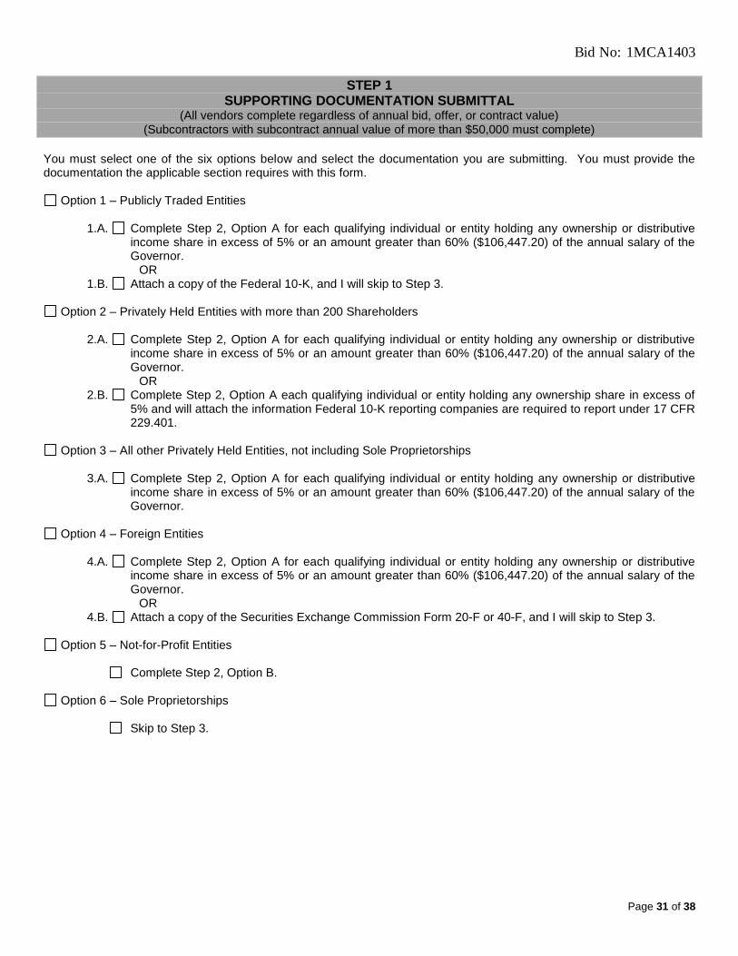
Bid No: 1MCA1403
Page 31 of 38
STEP 1 SUPPORTING DOCUMENTATION SUBMITTAL
(All vendors complete regardless of annual bid, offer, or contract value) (Subcontractors with subcontract annual value of more than $50,000 must complete)
You must select one of the six options below and select the documentation you are submitting. You must provide the documentation the applicable section requires with this form.
Option 1 – Publicly Traded Entities
1.A. Complete Step 2, Option A for each qualifying individual or entity holding any ownership or distributive income share in excess of 5% or an amount greater than 60% ($106,447.20) of the annual salary of the Governor.
OR 1.B. Attach a copy of the Federal 10-K, and I will skip to Step 3.
Option 2 – Privately Held Entities with more than 200 Shareholders
2.A. Complete Step 2, Option A for each qualifying individual or entity holding any ownership or distributive
income share in excess of 5% or an amount greater than 60% ($106,447.20) of the annual salary of the Governor.
OR 2.B. Complete Step 2, Option A each qualifying individual or entity holding any ownership share in excess of
5% and will attach the information Federal 10-K reporting companies are required to report under 17 CFR 229.401.
Option 3 – All other Privately Held Entities, not including Sole Proprietorships
3.A. Complete Step 2, Option A for each qualifying individual or entity holding any ownership or distributive
income share in excess of 5% or an amount greater than 60% ($106,447.20) of the annual salary of the Governor.
Option 4 – Foreign Entities
4.A. Complete Step 2, Option A for each qualifying individual or entity holding any ownership or distributive
income share in excess of 5% or an amount greater than 60% ($106,447.20) of the annual salary of the Governor.
OR 4.B. Attach a copy of the Securities Exchange Commission Form 20-F or 40-F, and I will skip to Step 3.
Option 5 – Not-for-Profit Entities
Complete Step 2, Option B.
Option 6 – Sole Proprietorships
Skip to Step 3.

Bid No: 1MCA1403
Page 32 of 38
STEP 2 DISCLOSURE OF FINANCIAL INTEREST OR BOARD OF DIRECTORS
(All vendors, except sole proprietorships, must complete regardless of annual bid, offer, or contract value) (Subcontractors with subcontract annual value of more than $50,000 must complete)
Complete either Option A (for all entities other than not-for-profits) or Option B (for not-for-profits). Additional rows may be inserted into the tables or an attachment may be provided if needed. OPTION A – Ownership Share and Distributive Income Ownership Share – If you selected Option 1.A., 2.A., 2.B., 3.A. or 4A. in Step 1, provide the name and address of each individual and entity and their percentage of ownership if said percentage exceeds 5%, or the dollar value of their ownership if said dollar value exceeds $106,447.20.
Check here if including an attachment with requested information in a format substantially similar to the format below.
TABLE - X
Name Address % of Ownership $ Value of Ownership
Distributive Income – If you selected Option 1.A., 2.A., 3.A., or 4A. in Step 1, provide the name and address of each individual and their percentage of the disclosing vendor’s total distributive income if said percentage exceeds 5% of the total distributive income of the disclosing entity, or the dollar value of their distributive income if said dollar value exceeds $106,447.20.
Check here if including an attachment with requested information in a format substantially similar to the format below.
TABLE - Y
Name Address % of Distributive Income $ Value of Distributive Income
Please certify that the following statements are true.
I have disclosed all individuals or entities that hold an ownership interest of greater than 5% or greater than $106,447.20. Yes No I have disclosed all individuals or entities that were entitled to receive distributive income in an amount greater than $106,447.20 or greater than 5% of the total distributive income of the disclosing entity. Yes No
OPTION B – Disclosure of Board of Directors (Not-for-Profits) If you selected Option 5 in Step 1, list members of your board of directors. Please include an attachment if necessary.
Name Address

Bid No: 1MCA1403
Page 33 of 38
STEP 3 DISCLOSURE OF LOBBYIST OR AGENT
(Complete only if bid, offer, or contract has an annual value over $25,000) (Subcontractors with subcontract annual value of more than $50,000 must complete)
Yes No. Is your company represented by or do you employ a lobbyist or other agent required to register under the
Lobbyist Registration Act (lobbyist must be registered pursuant to the Act with the Secretary of State) or other agent who is not identified through Step 2, Option A above and who has communicated, is communicating, or may communicate with any University officer or employee concerning the bid or offer? If yes, please identify each lobbyist and agent, including the name and address below.
Name Address Relationship to Disclosing Entity
Describe all costs/fees/compensation/reimbursements related to the assistance provided by each representative lobbyist or other agent to obtain a State/University contract:
STEP 4 PROHIBITED CONFLICTS OF INTEREST
(All vendors must complete regardless of annual bid, offer, or contract value) (Subcontractors with subcontract annual value of more than $50,000 must complete)
Step 4 must be completed for each person disclosed in Step 2, Option A and for sole proprietors identified in Step 1, Option 6 above. Please provide the name of the person for which responses are provided: 1. Do you hold or are you the spouse or minor child of any person who holds an elective office in
the State of Illinois or hold a seat in the General Assembly? Yes No
2. Have you, your spouse, or minor child been appointed to or employed in any offices or agencies of State government and receive compensation for such employment in excess of 60% ($106,447.20) of the salary of the Governor?
Yes No
3. Are you or are you the spouse or minor child of an officer or employee of the Capital Development Board or the Illinois Toll Highway Authority?
Yes No
4. Have you, your spouse, or an immediate family member who lives in your residence currently or who lived in your residence within the last 12 months been appointed as a member of a board, commission, authority, or task force authorized or created by State law or by executive order of the Governor?
Yes No
5. If you answered yes to any question in 1-4 above, please answer the following: Do you, your spouse, or minor child receive from the vendor more than 7.5% of the vendor’s total distributable income or an amount of distributable income in excess of the salary of the Governor ($177,412.00)?
Yes No
6. If you answered yes to any question in 1-4 above, please answer the following: Is there a combined interest of self with spouse or minor child more than 15% ($354,824.00) in the aggregate of the vendor’s distributable income or an amount of distributable income in excess of two times the salary of the Governor?
Yes No
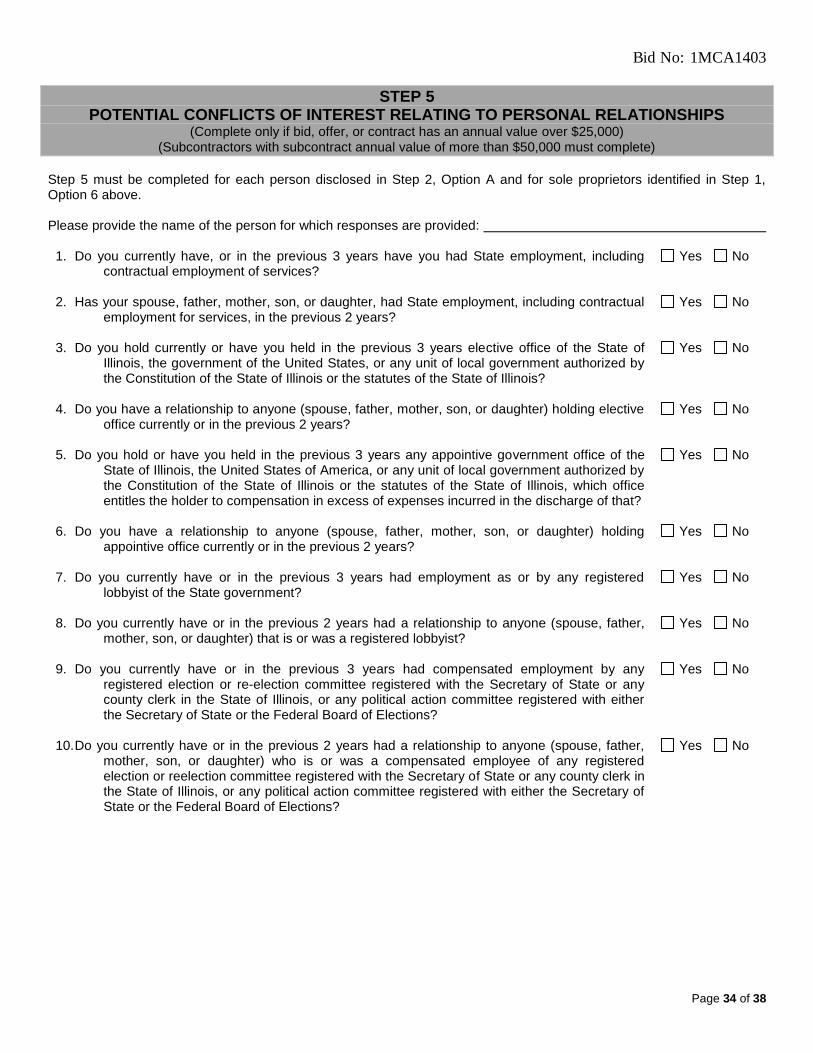
Bid No: 1MCA1403
Page 34 of 38
STEP 5 POTENTIAL CONFLICTS OF INTEREST RELATING TO PERSONAL RELATIONSHIPS
(Complete only if bid, offer, or contract has an annual value over $25,000) (Subcontractors with subcontract annual value of more than $50,000 must complete)
Step 5 must be completed for each person disclosed in Step 2, Option A and for sole proprietors identified in Step 1, Option 6 above. Please provide the name of the person for which responses are provided:
1. Do you currently have, or in the previous 3 years have you had State employment, including contractual employment of services?
Yes No
2. Has your spouse, father, mother, son, or daughter, had State employment, including contractual employment for services, in the previous 2 years?
Yes No
3. Do you hold currently or have you held in the previous 3 years elective office of the State of Illinois, the government of the United States, or any unit of local government authorized by the Constitution of the State of Illinois or the statutes of the State of Illinois?
Yes No
4. Do you have a relationship to anyone (spouse, father, mother, son, or daughter) holding elective office currently or in the previous 2 years?
Yes No
5. Do you hold or have you held in the previous 3 years any appointive government office of the State of Illinois, the United States of America, or any unit of local government authorized by the Constitution of the State of Illinois or the statutes of the State of Illinois, which office entitles the holder to compensation in excess of expenses incurred in the discharge of that?
Yes No
6. Do you have a relationship to anyone (spouse, father, mother, son, or daughter) holding appointive office currently or in the previous 2 years?
Yes No
7. Do you currently have or in the previous 3 years had employment as or by any registered lobbyist of the State government?
Yes No
8. Do you currently have or in the previous 2 years had a relationship to anyone (spouse, father, mother, son, or daughter) that is or was a registered lobbyist?
Yes No
9. Do you currently have or in the previous 3 years had compensated employment by any registered election or re-election committee registered with the Secretary of State or any county clerk in the State of Illinois, or any political action committee registered with either the Secretary of State or the Federal Board of Elections?
Yes No
10. Do you currently have or in the previous 2 years had a relationship to anyone (spouse, father, mother, son, or daughter) who is or was a compensated employee of any registered election or reelection committee registered with the Secretary of State or any county clerk in the State of Illinois, or any political action committee registered with either the Secretary of State or the Federal Board of Elections?
Yes No
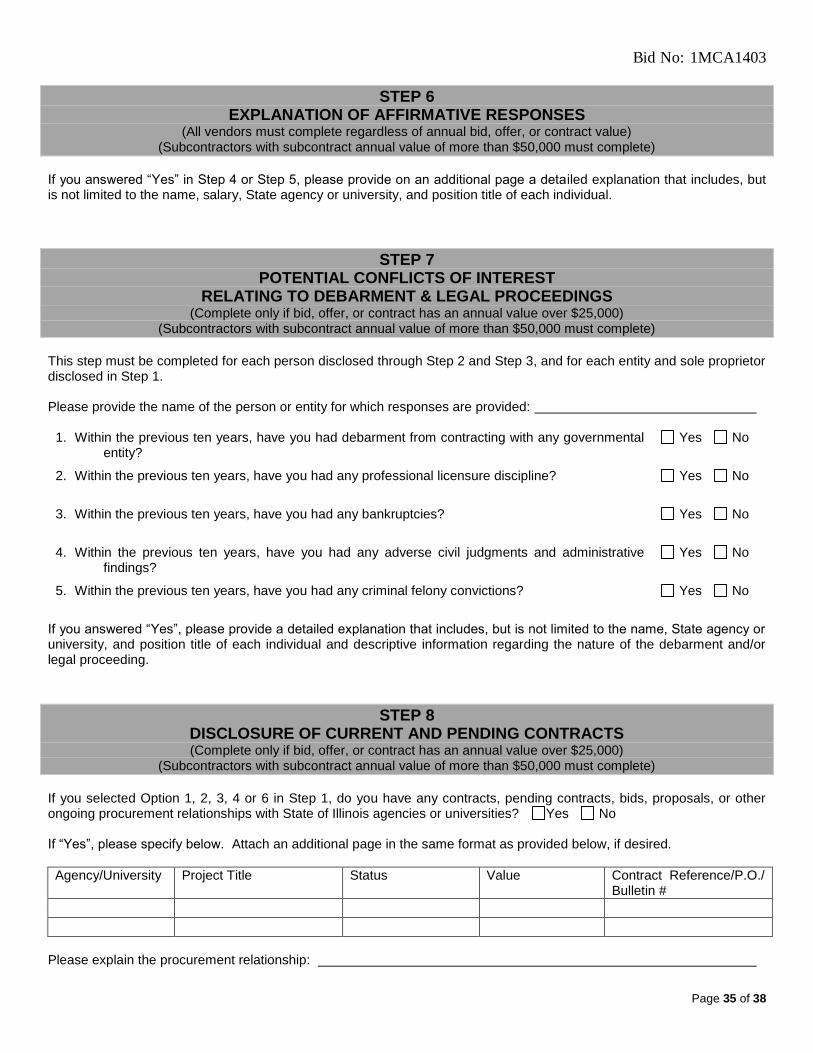
Bid No: 1MCA1403
Page 35 of 38
STEP 6 EXPLANATION OF AFFIRMATIVE RESPONSES
(All vendors must complete regardless of annual bid, offer, or contract value) (Subcontractors with subcontract annual value of more than $50,000 must complete)
If you answered “Yes” in Step 4 or Step 5, please provide on an additional page a detailed explanation that includes, but is not limited to the name, salary, State agency or university, and position title of each individual.
STEP 7 POTENTIAL CONFLICTS OF INTEREST
RELATING TO DEBARMENT & LEGAL PROCEEDINGS (Complete only if bid, offer, or contract has an annual value over $25,000)
(Subcontractors with subcontract annual value of more than $50,000 must complete)
This step must be completed for each person disclosed through Step 2 and Step 3, and for each entity and sole proprietor disclosed in Step 1. Please provide the name of the person or entity for which responses are provided:
1. Within the previous ten years, have you had debarment from contracting with any governmental entity?
Yes No
2. Within the previous ten years, have you had any professional licensure discipline? Yes No
3. Within the previous ten years, have you had any bankruptcies? Yes No
4. Within the previous ten years, have you had any adverse civil judgments and administrative findings?
Yes No
5. Within the previous ten years, have you had any criminal felony convictions? Yes No
If you answered “Yes”, please provide a detailed explanation that includes, but is not limited to the name, State agency or university, and position title of each individual and descriptive information regarding the nature of the debarment and/or legal proceeding.
STEP 8 DISCLOSURE OF CURRENT AND PENDING CONTRACTS (Complete only if bid, offer, or contract has an annual value over $25,000)
(Subcontractors with subcontract annual value of more than $50,000 must complete)
If you selected Option 1, 2, 3, 4 or 6 in Step 1, do you have any contracts, pending contracts, bids, proposals, or other ongoing procurement relationships with State of Illinois agencies or universities? Yes No If “Yes”, please specify below. Attach an additional page in the same format as provided below, if desired.
Agency/University Project Title Status Value Contract Reference/P.O./ Bulletin #
Please explain the procurement relationship:

Bid No: 1MCA1403
Page 36 of 38
STEP 9 SIGN THE DISCLOSURE
(All vendors must complete regardless of annual bid, offer, or contract value) (Subcontractors with subcontract annual value of more than $50,000 must complete)
This disclosure is signed and made under penalty of perjury by an authorized officer or employee on behalf of the bidder or offeror pursuant to Sections 50-13 and 50-35 of the Illinois Procurement Code. This disclosure information is submitted on behalf of: Name of Disclosing Entity: Signature: Date: Printed Name: Title: Phone Number: Email Address:

Bid No: 1MCA1403
Page 37 of 38
EXHIBIT C. Additional Conditions for Submitting Formal Bids and Proposals
1. Registration with State Board of Elections
In accordance with 30 ILCS 500/20-160, Vendor certifies that either:
1. Vendor is not required to register as a business entity with the State Board of Elections because:
Vendor is a not-for-profit entity;
Vendor is a governmental organization; or
the annual total value of all of Vendor’s contracts and offers with all State agencies (including all current State
contracts, the bid or proposal Vendor is submitting, any other pending offers, and offers Vendor previously submitted this year where Vendor was not awarded a contract) does not exceed $50,000.
OR
2. Vendor has completed electronic registration as a business entity with the State Board of Elections. Please attach a copy of the
official certificate of electronic registration as issued by the State Board of Elections to this Exhibit C. In addition, Vendor acknowledges a continuing duty to update the registration as required by the Act
Further information about the electronic registration process is available from the Board of Elections at:
https://berep.elections.il.gov/
2. Illinois Department of Human Rights (DHR) Public Contracts Number
If Vendor employs 15 or more full-time employees in Illinois, Vendor must have a current Public Contract Number or have proof of having submitted a completed application to DHR. Please complete the appropriate sections below.
Name of Company (and D/B/A): _____________________________________________________
DHR Public Contracts Number: _____________________________________________________
Date of Expiration: _____________________________________________________
____ (check if applicable) The DHR number is not required because Vendor has employed 14 or fewer full-time employees in Illinois during the last 365-day period.
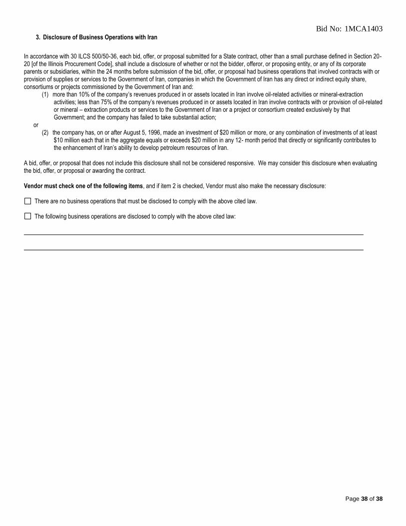
Bid No: 1MCA1403
Page 38 of 38
3. Disclosure of Business Operations with Iran
In accordance with 30 ILCS 500/50-36, each bid, offer, or proposal submitted for a State contract, other than a small purchase defined in Section 20-20 [of the Illinois Procurement Code], shall include a disclosure of whether or not the bidder, offeror, or proposing entity, or any of its corporate parents or subsidiaries, within the 24 months before submission of the bid, offer, or proposal had business operations that involved contracts with or provision of supplies or services to the Government of Iran, companies in which the Government of Iran has any direct or indirect equity share, consortiums or projects commissioned by the Government of Iran and:
(1) more than 10% of the company’s revenues produced in or assets located in Iran involve oil-related activities or mineral-extraction activities; less than 75% of the company’s revenues produced in or assets located in Iran involve contracts with or provision of oil-related or mineral – extraction products or services to the Government of Iran or a project or consortium created exclusively by that Government; and the company has failed to take substantial action;
or (2) the company has, on or after August 5, 1996, made an investment of $20 million or more, or any combination of investments of at least
$10 million each that in the aggregate equals or exceeds $20 million in any 12- month period that directly or significantly contributes to the enhancement of Iran’s ability to develop petroleum resources of Iran.
A bid, offer, or proposal that does not include this disclosure shall not be considered responsive. We may consider this disclosure when evaluating the bid, offer, or proposal or awarding the contract. Vendor must check one of the following items, and if item 2 is checked, Vendor must also make the necessary disclosure:
There are no business operations that must be disclosed to comply with the above cited law.
The following business operations are disclosed to comply with the above cited law:

©Stanley Consultants, Inc. 2013
00 01 01.doc
Project Manual for Boiler Procurement Gas Boiler Replacement Project (U12145) University of Illinois at Urbana-Champaign Urbana, Illinois
Revision 2
April 2013


24182.01.00 TABLE OF CONTENTS ms1259 SECTION 00 01 10 - Page 1
PACKAGE 1- BOILER PROCUREMENT GAS BOILER REPLACEMENT PROJECT (U12145)
UNIVERSITY OF ILLINOIS AT URBANA-CHAMPAIGN
URBANA, ILLINOIS
SPECIFICATIONS GROUP
GENERAL REQUIREMENTS SUBGROUP
Section Title Page DIVISION 01 GENERAL REQUIREMENTS 01 11 00 Summary of Work 1 thru 2 01 25 13 Product Substitutions Procedures 1 thru 2 Product Substitution Request Form 1 01 33 00 Submittal Procedures 1 thru 5 Submittal Transmittal Form 1 01 40 00 Quality Requirements 1 thru 3 01 45 16 Field Quality Control 1 thru 2 01 60 00 Product Requirements 1 01 78 23 Operating and Maintenance Data 1 thru 4 Operating and Maintenance Manual Cover Diagram 1
FACILITY SERVICES SUBGROUP DIVISION 23 HEATING, VENTILATING, AND AIR CONDITIONING 23 52 33 Packaged Water Tube Boiler 1 thru 14 DIVISION 26 ELECTRICAL 26 05 00 Common Work Results for Electrical Packaged Equipment 1 thru 8 26 05 09 Large Motors 1 thru 10 26 18 39-13 Medium-Voltage Variable Frequency Drives 1 thru 8
PROCESS EQUIPMENT SUBGROUP DIVISION 40 PROCESS INTEGRATION 40 05 23 General Duty Process Valves and Accessories 1 thru 9 DIVISION 44 POLLUTION CONTROL EQUIPMENT 44 11 39-13 Fabricated Stack 1 thru 5 REFERENCE DRAWINGS Bound Herein
X01 - Main Floor Boiler Areas X02 - Boiler #4 Bay South Elevation X03 - Boilers #3 and #4 Bay East Elevation
24182.01.00 SUMMARY OF WORK ms1259 SECTION 01 11 00 - Page 1, Rev. 2
PART 1 GENERAL
1.01 WORK COVERED BY CONTRACT DOCUMENTS
A. Procurement of dual-fuel packaged water-tube steam generating boiler. Dual-fuel boiler shall have natural gas as primary fuel and No. 2 fuel oil as secondary fuel. Boiler shall be capable of producing
175,000 pounds per hour (pph) of steam at 850 psig and 740°F. Boiler shall be factory-fabricated boiler package including following items: 1. Steam generation boiler with superheat system. 2. Feed water economizer. 3. Forced draft fan, motor and variable frequency drive. 4. Dual fuel burner system with NFPA 85 required safety systems and devices. 5. Boiler flue gas stack and connecting duct work. 6. Boiler safety relief valves with drip pan elbows. 7. Boiler non-return valve. 8. Boiler stop valve. 9. Instrument nozzle connections as defined in remainder of specifications. 10. Services of qualified installation field service technical representative during offloading, placement,
and start-up and commissioning of boiler equipment package. 11. Services of qualified technical training representative for training of operating and maintenance
personnel at Abbott Power Plant for a three 8-hour periods as determined by Buyer. Training shall cover all components of boiler equipment package.
12. An option price for 2-year maintenance contract for manufacturer-required maintenance items including normal wear items as provided in a listing provided with Proposal.
13. An option price for delivery of an identical boiler equipment package between 2014 and 2020. 14. An option price for five additional 2-year service and spare parts purchase contracts at conclusion
of first maintenance and spare parts contract. 15. Seller may propose a contract price for yearly preventative maintenance contract. 16. Alternate component pricing for boiler and economizer soot blower equipment. 17. Alternate pricing component to provide insulation thickness sufficient to provide 120°F (48.9°C)
with an ambient temperature of 90°F (32°C), surface emissivity of 0.10, and ambient wind speed of 2 fps (0.61 m/s).
1.02 AGREEMENT
A. Furnish and deliver Goods under single lump sum Agreement.
1.03 WORK BY OTHERS
A. Work on Project which will be executed after completion of Work of this Agreement, and which is excluded from this Agreement is as follows: 1. Receiving, unloading, and installation of boiler and ancillary equipment. 2. Installation of boiler control panel consisting of burner management system (BMS) and
combustion control system (CCS). 3. Programming and configuration of BMS and CCS logic.
1.04 WORK SEQUENCE
A. Furnish Buyer with schedule of engineering, fabrication, testing, and delivery dates.
B. Changes to final delivery date will be approved in writing by Buyer.
C. Anticipated Project sequence: 1. Notice of Award: September 20, 2013. 2. Seller submits Shop Drawings: November 1, 2013. 3. Equipment delivered on Site: on or before July 20, 2014. 4. Installation complete, by others: October 31, 2014. 5. Startup: November 1, 2014.

SUMMARY OF WORK 24182.01.00 Page 2 - SECTION 01 11 00, Rev. 2 ms1259
6. Testing and commissioning complete: December 1, 2014.
D. Final schedule: 1. Final schedule shall be coordinated with Buyer following Notice to Proceed. 2. Proposal shall allow variation in schedule of plus or minus 4 weeks, at Buyer’s option, from
anticipated dates without change in price.
E. Coordinate delivery schedule with Buyer.
1.05 DELIVERY OF GOODS
A. Buyer will occupy premises during delivery for conduct of its normal operations. Cooperate with Buyer in all operations to minimize conflict and to facilitate Buyer usage.
B. Location: Freight on Board (FOB), near University of Illinois Urbana-Champaign, Abbott Power Plant, Champaign, Illinois. Final delivery location to be determined by Owner’s installing contractor.
C. Access to site for delivery of Goods shall be coordinated with Buyer prior to shipment.
D. Installing contractor will be responsible for rigging and offloading equipment under supervision of boiler equipment manufacturer’s field service representative.
PART 2 PRODUCTS
NOT USED
PART 3 EXECUTION
NOT USED
END OF SECTION

24182.01.00 PRODUCT SUBSTITUTIONS PROCEDURES ms1259 SECTION 01 25 13 - Page 1
PART 1 GENERAL
1.01 SUBSTITUTIONS
A. Proposed Substitutions must be submitted to the Buyer by April 5, 2013. Buyer will respond to request for substitution no later than April 12, 2013. After this date, substitution requests will be considered only in case of product unavailability or other conditions beyond control of Seller.
B. Submit copy of request for substitution for consideration using attached Product Substitution Request Form. Limit each request to one proposed Substitution. Support each request with: 1. Complete data substantiating compliance of proposed substitutions with requirements stated in
Contract Documents. Burden of proof is on proposer. a. Product identification, including manufacturer's name and address. b. Manufacturer's literature; identify:
1) Product description. 2) Reference standards. 3) Performance and test data.
c. Samples, as applicable. d. Name and address of similar projects on which product has been used, and date of each installation.
2. Itemized comparison of proposed substitution with product specified; list significant variations. 3. Data relating to changes in construction schedule. 4. Any effect of substitution on separate contracts. 5. List of changes required in other work or products. 6. Accurate cost data comparing proposed substitution with product specified. Amount of any net
change to Contract Price. 7. Designation of required license fees or royalties. 8. Designation of availability of maintenance services, sources, or replacement materials.
C. Substitutions will not be considered for acceptance when: 1. They are indicated or implied on Shop Drawings. 2. They are requested directly by Subcontractor or supplier. 3. Acceptance will require substantial revision of Contract Documents.
D. Substitute products shall not be ordered or installed without written notification from Engineer of Buyer's acceptance.
E. Engineer will determine acceptability of proposed substitutions.
1.02 SELLER'S REPRESENTATION
A. In making formal request for substitution Seller represents that: 1. It has investigated proposed product and has determined that it is equal to or superior in all
respects to that specified. 2. It will provide same warranties or Bonds for substitution as for product specified or as required by
Buyer. 3. It will coordinate installation of accepted substitution into Goods, and will make such changes as
may be required for Goods to be complete in all respects. 4. It waives claims for additional costs caused by substitution which may subsequently become
apparent. 5. Cost data is complete and includes related costs under its Agreement, but not:
a. Costs under separate contracts. b. Engineer's costs for redesign or revision of Contract Documents.
6. It will reimburse Buyer for charges of Engineer or Engineer's consultants for evaluating any proposed substitute, whether proposed substitute is accepted or rejected.

PRODUCT SUBSTITUTION PROCEDURES 24182.01.00 Page 2 - SECTION 01 25 13 ms1259
1.03 ENGINEER DUTIES
A. Review Seller's requests for substitution with reasonable promptness and advise Buyer.
B. Notify Seller in writing of Buyer's decision to accept or reject requested substitution.
PART 2 PRODUCTS
NOT USED
PART 3 EXECUTION
NOT USED
END OF SECTION

PRODUCT SUBSTITUTION REQUEST FORM
To: Project: Specified Item: Section Page Paragraph Description The undersigned request consideration of the following: PROPOSED SUBSTITUTION Attached data includes product description, specifications, drawings, photographs, performance, and test data adequate for evaluation of the request; applicable portions of the data are clearly identified. Attached data also includes a description of changes to the Contract Documents that the proposed substitution will require for its proper installation. The undersigned certifies that the following paragraphs, unless modified by attachments are correct:
1. The proposed substitution does not affect specified dimensions.
2. The undersigned will pay for changes to the design, including engineering design, detailing, and construction costs caused by the requested substitution.
3. The proposed substitution will have no adverse affect on other trades, the construction schedule, or
specified warranty requirements.
4. Maintenance and service parts will be locally available for the proposed substitution. The undersigned further states that the function, appearance, and quality of the proposed substitution are equivalent or superior to the specified item. Submitted by: Signature For use by Engineer
Firm Approved Approved as noted
Address Not Approved Received too late By Date Date Telephone Remarks Attachments

24182.01.00 SUBMITTAL PROCEDURES ms1259 SECTION 01 33 00 - Page 1, Rev. 1
PART 1 GENERAL
1.01 SUBMITTAL PROCEDURES
A. Submit Shop Drawings as follows: 1. One set electronic shop drawings to Engineer at [email protected]. 2. One set electronic shop drawings to Buyer at [email protected]. 3. One set electronic shop drawings to [email protected] 4. One paper set to Buyer: Ms. Alaina Davis
Facilities and Services Construction Division Physical Plant Services Building, MC-800 1501 S. Oak St. Champaign, IL 61820
B. Submittals shall be in English language.
C. Weights, measures, and units shall be English units with SI metric values following in parenthesis.
D. Symbols and drawings shall conform to ANSI Y32.2/IEEE 315/CSA Z99.
E. Seller’s Shop Drawings shall be submitted complete within 6 weeks of signed Contract.
F. Provide expected schedule of Shop Drawing submittals with Proposal.
1.02 SUBMITTALS REQUIRED WITH REQUEST FOR PROPOSAL (RFP)
A. Preliminary P&ID’s of boiler equipment package.
B. Boiler predicted performance data for both natural gas and #2 Fuel Oil firing at 100, 75, 50, 25%, and 10% load for following: 1. Steam generation. 2. Steam outlet pressure and temperature. 3. Fuel rate. 4. Combustion air rate. 5. Flue gas recirculation rate. 6. Flue gas exhaust rate. 7. Net heat release rate. 8. Liberation rate. 9. Excess air and O2. 10. Draft losses. 11. Boiler FD fan horsepower 12. Anticipated boiler emissions:
a. NOx:__________ b. CO:__________ c. SOx:_________ d. 2.5 PPM: e. VOC:___________
13. Furnace flue gas exit temperature. 14. Boiler flue gas exit temperature. 15. Economizer flue gas exit temperature. 16. Economizer leaving water temperature 17. Radiated, Convective and Unaccounted losses. 18. Boiler efficiency.
C. Boiler equipment package general arrangement showing equipment fit and layout in drawings provided with bid package. Drawings shall show required maintenance areas including tube pull, and

SUBMITTAL PROCEDURES 24182.01.00 Page 2, Rev. 1 - SECTION 01 33 00 ms1259
burner pull space requirements. Drawings shall include all boiler system equipment being provided by boiler manufacturer.
D. Estimated maintenance yearly repair requirements and hourly effort for first 10 years of operations using manufacturer maintenance and repair contract personnel.
E. And other submittals as required in specification sections herein.
1.03 SELLER RESPONSIBILITIES
A. Review submittals prior to submission.
B. Determine and verify: 1. Field construction criteria. 2. Catalog numbers and similar data. 3. Conformance to Specifications.
C. Coordinate each submittal with other submittals and with requirements of Goods and Special Services and of Contract Documents.
D. Notify Engineer in writing, at time of submission, of any deviations in submittals from requirements of Contract Documents. Any such deviations permitted by Engineer will require modification of Contract Documents.
E. Provide space on Shop Drawings for Seller stamps and review comments.
F. When Shop Drawings are revised for resubmission, identify all changes made since previous submission.
G. Submittals containing language imposing duties on others (such as verification of dimensions or supply of related information) inconsistent with contract language shall be null and void.
H. Submittals shall not be used as media for inquiries for information or for verification of information that must be supplied by others to Seller. Inquiries or verification of information shall be made by separate Seller submittal using Request for Information (RFI) process.
I. Begin no fabrication of Goods requiring submittal review until return of submittals by Engineer with stamp, as either "Reviewed", “Reviewed as Noted", or “Reviewed as Noted-Resubmit.”
J. Distribute copies of reviewed submittals that carry reviewer stamp as either "Reviewed" or "Reviewed as Noted" as appropriate. Instruct parties to promptly report any inability to comply with requirements.
K. Submittals not requested will not be recognized or processed.
1.04 ENGINEER DUTIES
A. Review required submittals with reasonable promptness and in accord with schedule, only for general conformance to design concept of Project and compliance with information given in Contract Documents. Review shall not extend to means, methods, sequences, techniques, or procedures of construction or to safety precautions or program incident thereto. Review of a separate item as such will not indicate approval of assembly in which item functions.
B. Affix stamp and initials or signature, and indicate requirements for resubmittal, or review of submittal. Engineer's action on submittals is classified as follows: 1. Reviewed: Submittal has been reviewed and appears to be in conformance to design concept of
Project and Contract Documents. Seller may proceed with fabrication of work in submittal.

24182.01.00 SUBMITTAL PROCEDURES ms1259 SECTION 01 33 00 - Page 3, Rev. 1
2. Reviewed As Noted: Submittal has been reviewed and appears to be in conformance to design
concept of Project and Contract Documents, except as noted by reviewer. Seller may proceed with fabrication of work in submittal with modifications and corrections as indicated by reviewer.
3. Reviewed As Noted-Resubmit: Submittal has been reviewed and appears to be in conformance to design concept of Project and Contract Documents, except as noted by reviewer. Seller may proceed with fabrication of work in submittal with modifications and corrections as indicated by reviewer. Seller shall make any corrections indicated by reviewer and resubmit for review.
4. Resubmit: Submittal has been reviewed and appears not to be in conformance to design concept of Project or with Contract Documents. Seller shall not proceed with fabrication of work in submittal, but instead shall make any corrections required by reviewer and resubmit for review.
5. Returned without Review: Submittal is being returned without having been reviewed because: 1) not required by Contract Documents; 2) grossly incomplete; 3) indicates no attempt at conformance to Contract Documents; 4) cannot be reproduced; 5) lacks Seller's completed approval stamp; or 6) lacks design professional's seal when required by law or Contract Documents. If submittal is required by Contract Documents, Seller shall not proceed with Work as detailed in submittal, but instead shall correct defects and resubmit for review.
6. For Information Only: Submittal has not been reviewed but is being retained for informational purposes only.
7. Void: Submittal is voided because it is no longer required or has been superseded by another submittal.
C. Return submittals to Seller electronically.
D. Review of submittals shall not relieve Seller from responsibility for any variation from Contract Documents unless Seller has, in writing, called Engineer's attention to such variation at time of submission, and Engineer has given written concurrence pursuant to Contract Documents to specific variation, nor shall any concurrence by Engineer or other reviewer relieve Seller from responsibility for errors or omissions in submittals.
1.05 SHOP DRAWINGS SUBMITTALS
A. Submit for review for limited purpose of checking for conformance to information given and design concept expressed in Contract Documents.
B. Designate in submittal schedule, dates for submission and dates that reviewed submittals will be needed.
C. Make submittals promptly in accordance with approved schedule, and in such sequence as to cause no delay in Work or in work of other Sellers.
D. Present in clear and thorough manner, complete with respect to dimensions, design criteria, materials of construction, and like information to enable review of information as required.
E. Indicate special utility and electrical characteristics, utility connection requirements, and location of utility outlets for service for functional equipment and appliances.
F. Equipment which is identified on Contract Documents with tag number or name shall be identified on Shop Drawing with same tag.
G. For each submittal for review, allow 15 days.
H. Identify variations from Contract Documents and product or system limitations which may be detrimental to successful performance of completed Work.
I. Shop Drawings: 1. Submitted in electronic format:
a. Text documents shall be submitted in .pdf format. b. Drawings shall be submitted in .pdf format. c. Electronic submittal shall be suitable for reproduction in black and white.

SUBMITTAL PROCEDURES 24182.01.00 Page 4, Rev. 1 - SECTION 01 33 00 ms1259
2. Submitted in paper format:
a. Text documents shall be submitted on 8-1/2” x 11” paper. b. Drawings shall be submitted in adequate size to allow review and legibility of drawing content. c. Submittal shall be suitable for reproduction in black and white.
J. Submittals shall contain: 1. Date of submission and dates of any previous submissions. 2. Project title and number. 3. Contract identification. 4. Names of:
a. Seller. b. Supplier. c. Manufacturer.
5. Identification of product, with Specification section number and article number. 6. Applicable standards, such as ASTM or Federal Specification numbers. 7. Identification of deviations from Contract Documents. 8. Identification of revisions on resubmittals. 9. An 8" x 3" blank space for Seller stamps and review comments. 10. Indication of Seller's approval, initialed or signed, with wording substantially as follows:
"Seller represents to Buyer and Engineer that Seller has either determined and verified all quantities, dimensions, materials, catalog numbers, and similar data, or assumes full responsibility for doing so and has reviewed or coordinated each submittal with requirements of Work and Contract Documents."
K. Product Data: 1. Mark each copy to identify applicable products, models, options, and other data. Supplement
manufacturers' standard data to provide information specific to this Project. 2. Indicate product utility and electrical characteristics, utility connection requirements, and location
of utility outlets for service for functional equipment and appliances.
L. Design data: 1. Submit for Engineer's knowledge as contract administrator or for Buyer. 2. Submit for information for limited purpose of assessing conformance with information given and
design concept expressed in Contract Documents.
M. Data sheets: 1. Data sheets may require information not known until Seller’s engineering is complete. Furnish
estimated values based on good engineering judgment. Estimated values shall be identified by placement of “(est.)” next to value.
2. Data Sheets shall be updated and resubmitted by Seller once final values are known. 3. Do not leave items blank or labeled “To Be Determined” or “Later.” 4. Do not submit manufacturer Product Data instead of completed data sheets.
N. Test reports: 1. Submit for Engineer's knowledge as contract administrator or for Buyer. 2. Submit test reports for information for limited purpose of assessing conformance with information
given and design concept expressed in Contract Documents.
O. Certificates: 1. When specified in individual specification sections, submit certification by manufacturer. 2. Indicate material or product conforms to or exceeds specified requirements. Submit supporting
reference data, affidavits, and certifications as appropriate. 3. Certificates may be recent or previous test results on material or product, but must be acceptable
to reviewer.
P. Manufacturer's instructions: 1. When specified in individual specification sections, submit instructions for delivery, storage,
assembly, installation, start-up, adjusting and finishing.

24182.01.00 SUBMITTAL PROCEDURES ms1259 SECTION 01 33 00 - Page 5, Rev. 1
2. Indicate special procedures, perimeter conditions requiring special attention, and special
environmental criteria required for application or installation.
Q. Erection drawings: 1. Submit for information for limited purpose of assessing conformance with information given and
design concept expressed in Contract Documents. 2. Data indicating inappropriate or unacceptable Work may be subject to action by Engineer or
Buyer.
R. Operations and maintenance manuals: 1. Designate in construction schedule, or in separate coordinated schedule, dates for submission
and dates that reviewed operations and maintenance manuals will be needed. 2. Operations and maintenance manuals shall be presented in clear and thorough manner, complete
with respect to dimensions, design criteria, materials of construction, and like information to enable reviewer to review information as required.
1.06 RESUBMISSION REQUIREMENTS
A. Make any corrections or changes in submittals required by Engineer and resubmit until stamped as either "Reviewed," "Reviewed as Noted," or “For Information Only.”
B. Text and depictions changed on Submittal shall be back-circled (clouded).
C. Engineer will assume that portions of Submittal not back-circled have not been changed by Seller from previous submission.
D. Indicate revision number and date in document revision block.
1.07 SUBMITTAL TRANSMITTAL FORM PROCEDURES
A. Submittals shall be accompanied by completed copies of Submittal Transmittal form, bound herein. An electronic version of transmittal form is available and may be obtained from Engineer. Reproduce additional copies required.
B. Submit transmittal form for initial submittals and resubmittals. Sequentially number transmittal form. Revise submittals with original number and sequential alphabetic suffix.
C. Prior to submittal, complete information under heading “Seller's Transmittal.”
D. Engineer will complete information under “Reviewer's Action.”
E. Do not include submittals for more than one section of Specifications in each transmittal.
F. Identify project title, location, and number and contract title and number.
G. Identify preparer name and, submittal number, including preparer’s submittal revision number.
H. A brief description under "Title" should clearly identify specific application of equipment or material covered by Submittal, utilizing same title used in Contract Documents, where possible.
I. Identify Specification Section number.
J. Apply Seller's stamp, signed or initialed certifying that review, approval, verification of products required and coordination of information is in accordance with requirements of Contract Documents.
PART 2 PRODUCTS NOT USED
SUBMITTAL PROCEDURES 24182.01.00 Page 6, Rev. 1 - SECTION 01 33 00 ms1259
PART 3 EXECUTION NOT USED
END OF SECTION

23535.01.00 SUBMITTAL PROCEDURES ms1148 SECTION 01 33 00 - Page 7
Date Received
Date Distributed SUBMITTAL TRANSMITTAL Transmittal No.
Project Title Gas Boiler Replacement Project No. 24182 Contract No. 1
Project Location UIUC, Champaign, Illinois Contract Title Boiler Procurement
SELLER'S TRANSMITTAL
ENGINEER’S/ARCHITECT’S ACTIONStatus Abbreviations:
R - Reviewed RS – ResubmitRN - Reviewed as Noted RET - Returned Without Review RNR – Reviewed as Noted Resubmit FIO - For Information Only
V – Void
Preparer Preparer Submittal No.
Rev. No.
Title Section No.
SC Submittal
No. Status
Distribution (No.)
Cont RPR Own Des
Seller Remarks
Address
By _________________________________ Date ______________________________
By Signature above, the Seller shall certify that they have reviewed the submittal and that they comply with all
applicable specification sections and contract drawings. Action of any kind on submittal by Engineer/Architect does not
relieve Seller from responsibility for errors, correctness of details, or conformance to the contract.
Engineer/Architect Remarks
By
Date

SC3001 R4 0907 SHOP DRAWING TRANSMITTAL

24182.01.00 QUALITY REQUIREMENTS ms1259 SECTION 01 40 00 - Page 1
PART 1 GENERAL
1.01 QUALITY CONTROL
A. Monitor quality control over suppliers, manufacturers, products, services and workmanship, to produce Goods of specified quality.
B. Comply with specified standards as minimum quality for Goods, except where more stringent tolerances, codes or specified requirements indicate higher standards or more precise workmanship.
C. Perform Work by persons qualified to produce required and specified quality.
1.02 TOLERANCES
A. Monitor fabrication and installation tolerance control of Goods. Do not permit tolerances to accumulate.
B. Comply with manufacturers' tolerances. Should manufacturers' tolerances conflict with Contract Documents, request clarification from Engineer before proceeding.
C. Adjust products to appropriate dimensions; position before securing products in place.
1.03 REFERENCES
A. For products or workmanship specified by association, trade, or other consensus standards, comply with requirements of the standard, except when more rigid requirements are specified or are required by applicable codes.
B. Conform to reference standard by date of issue current on date for receiving bids, except where a specific date is established by code.
C. Obtain copies of standards where required by product specification sections.
D. Should specified reference standards conflict with Contract Documents, request clarification from the Engineer before proceeding.
E. Neither contractual relationships, duties, nor responsibilities of the parties in Contract nor those of the Engineer shall be altered from the Contract Documents by mention or inference otherwise in any reference document.
F. Abbreviations used in Contract Documents are as specified in ASME Y14.38 and IEEE 260.
G. Schedule of references: 1. ABMA - American Bearing Manufacturers Association 2. AISC - American Institute of Steel Construction 3. ANSI - American National Standards Institute 4. ASME - American Society of Mechanical Engineers 5. ASTM – International Standards Worldwide 6. AWS - American Welding Society 7. CSA - Canadian Standards Association. 8. ICEA - Insulated Cable Engineers Association 9. IEEE - Institute of Electrical and Electronics Engineers 10. ISO - International Standards Organization 11. NEMA - National Electrical Manufacturers' Association 12. NFPA - National Fire Protection Association 13. OSHA – U. S. Department of Labor, Occupational Safety and Health Administration 14. SSPC – The Society for Protective Coatings

QUALITY REQUIREMENTS 24182.01.00 Page 2 - SECTION 01 40 00 ms1259
15. UL - Underwriters' Laboratories, Inc.
1.04 WELDING REQUIREMENTS
A. Welding shall be performed by qualified welding operators using procedures which have been qualified in accordance with applicable codes and standards: 1. ANSI B31.1 Code for Pressure Piping. 2. ASME Boiler and Pressure Vessel Code. 3. AWS D1.1 Structural Welding Code.
B. Procedure qualification: 1. Fabricator performing welding under jurisdiction of referenced codes shall be responsible for
obtaining and qualifying welding procedures. Structural welding procedures conforming to AWS D1.1 are prequalified as defined in AWS D1.1, Chapter 5 and Appendix E.
2. Seller shall maintain records, and make available to Engineer and Buyer when requested, certifying successful completion of procedure qualification tests.
C. Performance qualification: 1. Fabricator performing welding under jurisdiction of referenced codes shall be responsible for
testing and qualifying its welding operators in accordance with applicable codes, using qualified procedures.
2. Unless welding operators have been previously qualified by Seller within last 6 months and have been continuously employed as welders by Seller following qualification, requalification tests must be performed.
D. Submittals: 1. Except for procedures exempted to AWS D1.1, Section 5.1, submit copy of each welding
procedure to Buyer and Engineer with certificate demonstrating successful qualification of welding procedures for each welding process: AWS D1.1 - Forms E-1, E-2, E-3, or ASME QW-483.
2. Prior to execution of any welding, submit to Buyer and Engineer copy of welder qualification form for each individual performing welding: AWS D1.1 Form E-4 or ASME QW-484.
1.05 SERVICE ENGINEER RESPONSIBILITIES
A. Seller shall provide a qualified Service Engineer(s), as necessary to: 1. Supervise assembly of equipment. 2. Inspect equipment after it is installed to assure that all details of installation are correct and that
equipment is prepared for operation in accordance with manufacturer's instructions and recommendations.
3. Check connections to equipment and adjust, or supervise adjustment of, control and indicating devices after equipment has been installed and connected.
4. Fully instruct Buyer's operating personnel in operation and maintenance of equipment. 5. Provide Seller and Engineer with duplicate copies of final alignment and clearance measurements
on all rotating or reciprocating equipment. Measurements shall clearly identify each piece of equipment.
6. Supervise preliminary operation of equipment and necessary adjustments.
B. Work and abilities of Service Engineer shall be subject to review of Buyer, Engineer and Contractor. If Buyer, Engineer or Contractor determines that any Service Engineer is not properly qualified, Seller shall replace Service Engineer upon written notification by Contractor. Seller shall provide resume of service technicians for boiler, burner, and FD fan packages for review by Buyer.
C. Seller shall provide continuity in assignment of Service Engineer to Work. In event substitution of Service Engineer is made which is not at request of Engineer, substitute's time for "familiarization" shall be at Seller's expense.
D. Seller shall provide 10 days of Service Engineer time with the bid. Service will be in 2 separate 5-day blocks. Daily service rates and per diem rates shall be included with Bid so Buyer has option to purchase additional Service Engineer time.

24182.01.00 QUALITY REQUIREMENTS ms1259 SECTION 01 40 00 - Page 3
E. Seller will provide, from manufacturer of equipment, Service Engineer who will perform functions
specified for equipment provided.
F. Seller shall pay for cost of time and trips to site of Service Engineer if additional time or trips are required because of defective workmanship, materials, or equipment furnished under this Agreement.
G. Buyer will be sole determining agent as to reasonableness of Service Engineer's claim for added compensation.
PART 2 PRODUCTS
NOT USED
PART 3 EXECUTION
NOT USED
END OF SECTION

24182.01.00 FIELD QUALITY CONTROL ms1259 SECTION 01 45 16 - Page 1, Rev. 1
PART 1 GENERAL
1.01 FIELD PERFORMANCE TESTS
A. After system or equipment and other equipment necessary for operation of Work are installed and in operating condition, Seller shall supervise operation of equipment or system for period sufficient to assure proper functioning, and make necessary observations, investigations, and adjustment.
B. Buyer will conduct tests it deems necessary to determine if equipment or systems function properly. If equipment or systems fail to function properly, or guaranteed performance is not indicated, Seller shall make necessary corrections, including replacement, at no cost to Buyer, and after such corrections are completed, demonstrate to Buyer that equipment or systems function properly and guaranteed performance is obtainable.
C. It is intent of Buyer to conduct, simultaneously, performance tests on all heat cycle and electric generating equipment components. These include steam generator and related equipment.
D. These performance tests will be scheduled as soon as practicable but not later than 120 days after all associated equipment have been placed in "on-line" operating service and proved capable for continuous normal operation. Shutdowns of limited duration for normal operational checks, inspections, and adjustments will not be considered as causing Goods to be incapable of continuous operation.
E. Delayed testing: 1. If any individual equipment component is operable but is not declared ready for testing within time
limit stated above and cannot be tested during initial scheduled performance tests, delayed performance tests will be conducted upon these Goods at later scheduled date.
2. All costs incidental to conducting delayed performance tests, except for cost of fuel, water, and Buyer's operating personnel, shall be borne by manufacturer, supplier, or supplier responsible for equipment which are not ready for testing at time of initial performance tests.
F. Performance tests: 1. Seller shall be responsible for each equipment component and shall notify Buyer in writing when
installation of its Goods is considered to be complete, in good operating condition, and ready for performance tests. a. This notice shall not be given until such time as all designed operational functions have been
positively proved in actual operation or by simulated operational tests. b. Simulated operational tests shall be made only when it is impractical to conduct an actual "in
operation" test. c. When simulated operational test involves sensing device, test shall establish operational
ability of sensing device. 2. Buyer will coordinate between concerned contractors and will establish schedule for performance
tests. Upon establishment of test schedule, Buyer will give minimum of 10 days' notice to all concerned parties.
3. Such tests as are deemed necessary by Buyer and Engineer to establish that equipment function properly and that guarantees are met will be conducted by Buyer.
4. Buyer will furnish fuel, oil, water, and one operating engineer for tests. 5. Seller shall witness tests and assist in their performance. 6. Station instruments, meters, pressure gages, and thermometers, supplemented by necessary
portable test instruments, will be used for tests. 7. All costs for initial performance tests, except for costs of Seller's personnel, will be borne by
Buyer.
G. If guaranteed performance is not achieved in initial or delayed performance tests, Seller shall make necessary changes and adjustments to equipment at no cost to Buyer and notify Buyer when ready for retesting or supplemental testing.
H. Retesting or supplemental testing:

FIELD QUALITY CONTROL 24182.01.00 Page 2, Rev. 1 - SECTION 01 45 16 ms1259
1. Buyer, after giving notice, will perform retesting or supplemental testing it deems necessary to
further check performance of Goods. 2. All costs, except for costs of fuel, oil, water, and Buyer's operating personnel, shall be borne by
Seller. 3. Buyer will render bill to be paid by Seller covering costs incurred by retesting or supplemental
testing, except as noted herein.
I. If there is serious question or disagreement regarding accuracy of test results and Seller considers tests of greater refinement necessary or desirable, Buyer, at Seller's request, may direct that further tests be conducted in accordance with ASME Power Test Codes. If so directed: 1. Seller shall make arrangements and provide facilities necessary for performance of ASME Power
Test Codes tests. 2. Buyer will furnish fuel, oil, water, and 1 operating engineer for tests. 3. Seller shall witness and assist in performance of tests. 4. Buyer shall reimburse Seller for actual cost of labor and materials for furnishing and installing
testing facilities only, as listed on itemized statement of costs to be submitted by Seller, only if ASME Power Test Codes tests reveal that equipment is performing in accordance with guarantees.
5. If ASME Power Test Codes tests indicate that equipment is not performing in accordance with guarantees, all costs of Buyer, Engineer, and Seller incidental to ASME Power Test Codes tests, except for fuel, water, and Buyer's operating personnel, shall be borne by Seller.
6. Billings to Seller for Buyer's or Engineer's costs for delayed testing, retesting, and supplemental testing, and ASME Power Test Codes testing as specified hereinbefore, shall be paid directly to Buyer or Engineer, as appropriate, within 30 calendar days from receipt by Seller. Seller's failure to pay such billings shall be cause for withholding final payment in amount equal to such costs.
J. Engineer's costs, when applicable, will be determined at Engineer's current per diem rates, plus direct expenses.
PART 2 PRODUCTS
NOT USED
PART 3 EXECUTION
NOT USED
END OF SECTION

24182.01.00 PRODUCT REQUIREMENTS ms1259 SECTION 01 60 00 - Page 1
PART 1 GENERAL
1.01 PRODUCTS
A. Provide products of qualified manufacturers suitable for intended use. Provide products of each type by a single manufacturer unless specified otherwise.
1.02 PRODUCT DELIVERY REQUIREMENTS
A. Transport and handle products in accordance with manufacturer's instructions.
B. Ensure that products comply with requirements, quantities are correct, and products are undamaged.
C. Provide equipment and personnel to handle products by methods to prevent soiling, disfigurement, or damage.
1.03 PRODUCT OPTIONS
A. For products specified only by reference standard, select product meeting that standard, by any manufacturer.
B. For products specified by naming several products or manufacturers, select any one of products and manufacturers named which complies with Specifications.
C. For products specified by naming one or more products or manufacturers and stating "or equal," submit request as for substitutions for any product or manufacturer which is not specifically named in accordance with Section 01 25 13.
D. For products specified by naming only one product and manufacturer, there is no option and no substitution will be allowed.
E. Whenever Specifications call for item by manufacturer's name and type and additional features of item are specifically required by Specifications, additional features specified shall be provided whether or not they are normally included in standard manufacturer's item listed.
1.04 SPARE PARTS
A. Provide startup and commissioning spare parts for all equipment provided.
PART 2 PRODUCTS
NOT USED
PART 3 EXECUTION
NOT USED
END OF SECTION
24182.01.00 OPERATING AND MAINTENANCE DATA ms1259 SECTION 01 78 23 - Page 1
PART 1 GENERAL
1.01 OPERATING AND MAINTENANCE DATA REQUIREMENTS
A. Operating and maintenance data shall be in English language.
B. Compile product data and related information appropriate for Buyer's maintenance and operation of products furnished under Agreement.
C. Prepare operating and maintenance data as specified in this section and as referenced in other pertinent sections of Specifications.
1.02 QUALITY ASSURANCE
A. Preparation of data shall be done by personnel: 1. Trained and experienced in maintenance and operation of described products. 2. Familiar with requirements of this section. 3. Skilled as technical writers to extent required to communicate essential data. 4. Skilled as draftsmen competent to prepare required drawings.
1.03 FORM OF SUBMITTALS
A. Prepare data in form of an instructional manual for use by Buyer's personnel. Provide 1 electronic format version of all manuals and 3 hard copy versions of all manuals as described below.
B. One copy of preliminary operations and maintenance manuals with estimated yearly preventative maintenance and repair costs shall be submitted with bid for use in life cycle costing analysis.
C. Format: 1. Sheet size: 8-1/2" x 11" minimum. 2. Paper: 20 lb minimum, white, for typed pages. 3. Text: Manufacturer's printed data, or neatly typewritten. 4. Drawings:
a. Provide reinforced punched binder tab, bind in with text. b. Larger size drawings shall be folded to 8-1/2” x 11”, and inserted into pockets.
5. Provide fly-leaf for each separate product, or each piece of operating equipment. a. Provide typed description of product, and major component parts of equipment. b. Provide indexed tabs.
6. Cover: Identify each volume with typed or printed title "OPERATING AND MAINTENANCE INSTRUCTIONS." List: a. Title of Project. b. Identity of general subject matter covered in manual.
7. Binders: a. Commercial quality 3-ring binders with durable and cleanable plastic covers. b. Maximum ring size: 1". c. When multiple binders are used, correlate data into related consistent groupings.
1.04 CONTENT OF MANUAL
A. Neatly typewritten table of contents for each volume, arranged in systematic order. 1. Seller, name of responsible principal, address, and telephone number. 2. Indicated Buyer-provided MEL number for each item in manual. 3. List of each product required to be included, indexed to content of volume. 4. List, with each product, name, address, and telephone number of:
a. Subcontractor or installer. b. Maintenance contractor, as appropriate. c. Identify area of responsibility of each. d. Local source of supply for parts and replacement and list of recommended spare parts.

OPERATING AND MAINTENANCE DATA 24182.01.00 Page 2 - SECTION 01 78 23 ms1259
5. Identify each product by product name and other identifying symbols as set forth in Contract
Documents, including nameplate information and shop order numbers for each item of equipment furnished.
B. Product data: 1. Include only those sheets which are pertinent to specific product. 2. Annotate each sheet to:
a. Clearly identify specific product or part installed. b. Clearly identify data applicable to installation. c. Delete references to inapplicable information.
C. Drawings: Supplement product data with Drawings as necessary to clearly illustrate following. 1. Relations of component parts of equipment and systems. 2. Control and flow diagrams. 3. Drawings shall use Buyer provided instrument and valve tag numbers.
D. Written text, as required to supplement product data for particular installation. 1. Organize in consistent format under separate headings for different procedures. 2. Provide logical sequence of instructions for each procedure.
E. Copy of each warranty, Bond, and service contract issued. 1. Provide information sheet for Buyer's personnel, giving:
a. Proper procedures in event of failure. b. Instances which might affect validity of warranties or Bonds.
1.05 MANUAL FOR EQUIPMENT AND SYSTEMS
A. Submit 3 hard copies of complete manual in final form, and 1 electronic version in final form.,
B. Contents, for each unit of equipment and system, as appropriate: 1. Description of unit and component parts:
a. Function, normal operating characteristics, and limiting conditions. b. Performance curves, engineering data, and tests. c. Complete nomenclature and commercial number of replaceable parts.
2. Operating procedures: a. Startup, break-in, routine, and normal operating instructions. b. Regulation, control, stopping, shutdown, and emergency instructions. c. Summer and winter operating instructions. d. Special operating instructions.
3. Maintenance procedures: a. Routine operations. b. Guide to "trouble-shooting." c. Disassembly, repair, and reassembly. d. Alignment, adjusting, and checking. e. Welding procedures used during shop construction.
4. Servicing and lubrication schedule: List of lubricants required with cross reference to compatible Mobil lubricant number
5. Manufacturer's printed operating and maintenance instructions. 6. Description of sequence of operation by control manufacturer. 7. Original manufacturer's parts list, illustrations, assembly drawings, and diagrams required for
maintenance. a. Predicted life of parts subject to wear. b. Items recommended to be stocked as spare parts.
8. As-installed control diagrams by controls manufacturer. 9. Chart of valve tag numbers, with location and function of each valve using Seller-provided valve
tag numbers. 10. List of original manufacturer's spare parts, manufacturer's current prices, and recommended
quantities to be maintained in storage. 11. Other data as required under pertinent sections of Specifications.

24182.01.00 OPERATING AND MAINTENANCE DATA ms1259 SECTION 01 78 23 - Page 3
C. Content, for each electrical and electronic system, as appropriate.
1. Description of system and component parts: a. Function, normal operating characteristics, and limiting conditions. b. Performance curves, engineering data, and tests. c. Complete nomenclature and commercial number of replacement parts.
2. Circuit directories of panelboards: a. Electrical service. b. Controls. c. Communications.
3. As-installed color-coded wiring diagrams. 4. Operating procedures:
a. Routine and normal operating instructions. b. Sequences required. c. Special operating instructions.
5. Maintenance procedures: a. Routine operations. b. Guide to "trouble-shooting." c. Disassembly, repair, and assembly. d. Adjustment and checking.
6. Manufacturer's printed operating and maintenance instructions. 7. List of original manufacturer's spare parts, manufacturer's current prices, and recommended
quantities to be maintained in storage. 8. Other data as required under pertinent sections of Specifications.
D. Additional requirements for operating and maintenance data: Respective sections of Specifications.
E. Provide complete information for products specified in: 1. 23 52 33: Packaged Water-Tube Boilers. 2. 26 05 09: Large Motors. 3. 26 18 39-13: Medium-Voltage Variable Frequency Drives. 4. 40 05 23: General Duty Process Valves and Accessories. 5. 44 11 39-13: Fabricated Stack.
1.06 SUBMITTAL SCHEDULE
A. Submit specified copies of completed data in final form a minimum of 15 days prior to shipment of Goods. Copy will be returned after acceptance, with comments, as necessary.
B. Submit specified copies of approved data in final form within 15 days after acceptance or receipt of comments, as applicable.
1.07 DEMONSTRATION AND INSTRUCTION OF BUYER'S PERSONNEL
A. Instruct Buyer's personnel in maintenance of products and in operation of equipment and systems. . Base contract shall include operator and mechanic training in 3 separate trips to project site. Each trip will consist of 8 hours of training for plant personnel.
B. Provide daily training rate and per diem.
C. Demonstrate operation and maintenance of products to Buyer's personnel 2 weeks prior to date of acceptance.
D. Demonstrate operation and maintenance of Goods to Buyer’s personnel by a qualified representative who is knowledgeable about the Project.
E. Utilize operation and maintenance manuals as basis for instruction. Review contents of manual with Buyer's personnel in detail to explain all aspects of operation and maintenance.
OPERATING AND MAINTENANCE DATA 24182.01.00 Page 4 - SECTION 01 78 23 ms1259
F. Demonstrate start-up, operation, control, adjustment, trouble-shooting, servicing, maintenance, and
shutdown of each item of equipment at scheduled time, at equipment location.
G. Prepare and insert additional data in operations and maintenance manuals when need for additional data becomes apparent during instruction.
H. Provide outline of training program to be provided to Buyer’s operations and maintenance personnel at proposal in GANT chart format covering manufacturing recommended training topics and duration.
PART 2 PRODUCTS
NOT USED
PART 3 EXECUTION
NOT USED
END OF SECTION

OPERATING AND MAINTENANCE MANUAL COVER DIAGRAM
UNIVERSITY OF
ILLINOIS URBANA-
CHAMPAIGN
BOILER NO(S). _____
BOILER
PROCUREMENT
VOLUME
NUMBER _____
UNIVERSITY OF ILLINOIS
URBANA-CHAMPAIGN
OPERATING AND MAINTENANCE MANUAL
FOR
BOILER NO(S). _____
VOLUME NUMBER _____
MANUFACTURER’S NAME
MANUFACTURER’S ADDRESS
STANLEY CONSULTANTS, INC.
MUSCATINE, IOWA
36 pt
36 pt
24 pt
36 pt
36 pt
36 pt
36 pt
24 pt
24 pt
14 pt
14 pt
SPINE
COVER
1. Imprinting shall be in Arial font. 2. Spine printing shall be 12-point. 3. Cover printing shall be in point sizes indicated. * If more than one volume is necessary, imprint cover with volume numbers.

24182.01.00 PACKAGED WATER TUBE BOILER ms1259 SECTION 23 52 33 - Page 1, Rev. 3
PART 1 GENERAL
1.01 SECTION INCLUDES
A. Furnish and deliver 1 shop-assembled, packaged-type, forced draft, D-type or O-type water tube boiler, accessories, and manufacturer’s field services.
B. Boiler trim.
C. Low-NOX burner.
D. Instrumentation.
E. Flue gas recirculation equipment.
F. Forced draft fan.
G. Economizer.
H. Superheater.
1.02 INFORMATIONAL SUBMITTALS
A. Submit with Bid: 1. Data sheets at end of section completely filled out. 2. Provide guaranteed maximum boiler load at which specified emission limits can be satisfied
without flue gas recirculation (FGR) for natural gas and No. 2 fuel oil.
B. Product Data: 1. Installation manuals. 2. Manufacturer's data report including shop and field inspection certificates as required by ASME
Boiler and Pressure Vessel Code (i.e., P-4, MTR, R-1, etc.). 3. Complete catalog information of boiler, burner and accessories showing arrangement and
construction of pressure parts, casing, internals and support frame. 4. Technical data including temperature rating and arrangement of refractory and insulation. 5. Amount of heating surface and combustion volume. 6. Weight of boiler empty, operating and flooded, including burner and accessories. 7. Water volume in boiler and in connected piping. 8. Weight of economizer empty and operating. 9. Performance data for Natural Gas and #2 Fuel Oil firing: At 10%, 25%, 50%, 75% and 100% of
maximum required output. 10. Provide maximum capable burner turn down rate for natural gas and No. 2 fuel oil. 11. ASME “P” Forms, Manufacturer’s data report, on boiler and economizer construction: Submit
after boiler and economizer are fabricated. 12. Recommended spare parts list with prices guaranteed for one year.
1.03 ACTION SUBMITTALS
A. Shop Drawings: 1. Composite arrangement drawings. 2. Outline drawings of component equipment. 3. Flow diagram of air and flue gas system locating and identifying function of each instrument and
tap connection. 4. Flow diagram of pressure parts locating and identifying function of each instrument connection. 5. Loading diagram of support frame. 6. Piping and Instrument Diagrams (P&IDs) which includes normal operating conditions, flows,
pressures, temperatures for each piece of equipment using Buyer-supplied instrument tag numbers.

PACKAGED WATER TUBE BOILER 24182.01.00 Page 2, Rev. 2 - SECTION 23 52 33 ms1259
B. Product Data:
1. Start-up procedures. 2. Piping connection sizes, locations, and types. 3. Connection allowable loads. Capability of steam nozzle and attachments to boiler shell to
withstand forces and moments imposed by connecting piping. 4. Design pressures and temperatures. 5. Sequence of operations. 6. Recommended anchorage of boiler support frame to foundation. 7. Furnace view port construction, locations. 8. Predicted external surface temperature of front, rear and sides of boiler. 9. ASME manufacturer's data sheets. 10. Information required for erection of all equipment, breeching/flue materials, trim and accessory
details, electrical wiring details. 11. FD fan curves, including curves for various speeds. Include, as a minimum:
a. Maximum and minimum speed. b. 100% (MCR), 75%, 50%, and 25%.
12. Information on insulation including binders. 13. Boiler trim:
a. Design, construction, and arrangement on boiler. b. Pressure drop across boiler non-return valve and boiler stop valve. c. Size, set pressure and capacity of safety valves. d. Sootblower nozzles with blind flanges will be provided with boiler. Sootblower equipment will
be provided as a pricing alternate. Provide schematic diagrams of sootblower piping. e. Bill of materials.
14. Burner, fuel valves, and piping trains: a. Main burner natural gas, fuel oil and atomizing steam pressures and flows at maximum
required firing rate. b. Igniter (pilot) fuel flow and burner pressure. c. Natural gas main fuel pressure at inlet and outlet of burner-mounted pressure regulator. d. Igniter (pilot) fuel (natural gas) pressures at inlet and outlet of burner-mounted pressure
regulators. e. Bill of materials.
15. Burner management system (BMS) sequence of operations, logic diagrams, and input/output list. 16. Instrument data sheets (in ISA format) for each instrument supplied. 17. MSDS sheets for applicable materials.
1.04 CLOSEOUT SUBMITTALS
A. Operation and maintenance manuals.
1.05 QUALITY ASSURANCE
A. Packaged boiler, economizer and accessories shall be designed and constructed in strict accordance with ASME Boiler and Pressure Vessel Code, Section I, Rules for Construction of Power Boilers, requirements and stamped and registered with National Board.
B. Packaged boiler and accessories shall conform to NFPA 85, NFPA 54, NFPA 31, state and local laws, regulations and codes having jurisdiction where plant is located. Champaign, Illinois.
C. Applicable components shall be designed and constructed in accordance with ASME Power Test Code and ABMA Manual of Industry Standards with additions or modifications as required by this specification.
D. Design structural components supplied with boiler package in accordance with IBC, AISC-LRFD, and ASME STS-1.
E. Motors shall be in accordance with NEMA MG-1 and IEEE 112.

24182.01.00 PACKAGED WATER TUBE BOILER ms1259 SECTION 23 52 33 - Page 3, Rev. 3
F. State and local building codes regarding pressure vessel design and installation shall supersede
manufacturer’s recommendations.
G. Nonboiler Boiler Code piping shall be in accordance with ASME B31.1.
1.06 DELIVERY, STORAGE AND HANDLING
A. Shipping: Minimize ship loose components of boiler package. Maximum size opening into boiler plant is 18’ (5.5 m) high x 15’ (4.5m) wide. Ship components in maximum sizes to minimize reassembly and still fit through plant opening.
B. Piping connections and other openings shall be plugged or capped to prevent entrance of foreign material.
C. Thoroughly coat exposed machined surfaces with rust preventative material.
D. Equipment shall be properly covered, skidded, and crated to facilitate handling and to withstand normal shipping and handling shocks and vibration.
E. Place desiccant in drums prior to shipping to prevent rust. Desiccant shall not contain silica.
1.07 TYPICAL FUEL ANALYSES
A. Natural gas (primary fuel, by volume): 1. Heating value (Btu/ft3): 1015.3 2. Ethane (%): 1.925 3. Propane (%): 0.178 4. Butane (%): 0.027 5. Isobutane (%): 0.026 6. Pentane (%): .018. 7. Methane (%): 95.931 8. Carbone Dioxide (%): 1.081 9. Nitrogen (%): 0.793 10. Hexane (%): .009 11. Heptane (%): .007 12. Octane (5): .003
B. Fuel oil (secondary fuel, by mass): 1. Heating value (Btu/lb): 19,351 2. Carbon (%): 86.87 3. Sulfur (%): 0.06 4. Hydrogen (%): 12.46 5. Nitrogen (%): <0.01 6. Oxygen (%): <0.54 7. Ash (%): 0.05
1.08 SITE CONDITIONS
A. Elevation above sea level (approximate): 740’.
B. Barometer (mean), inches of Hg: 29.14.
C. Outdoor temperature, dry bulb: 1. Maximum: 115°F. 2. Minimum: -20°F.
D. Relative humidity: 60%.
E. Indoor temperature, dry bulb:
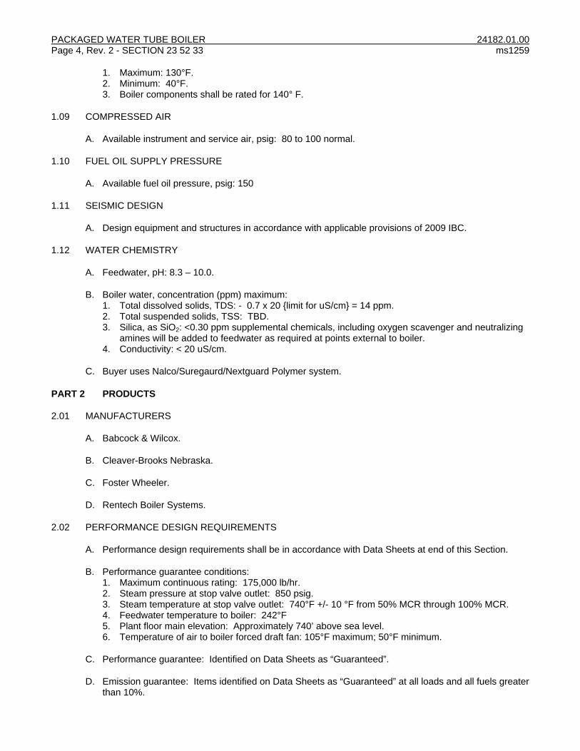
PACKAGED WATER TUBE BOILER 24182.01.00 Page 4, Rev. 2 - SECTION 23 52 33 ms1259
1. Maximum: 130°F. 2. Minimum: 40°F. 3. Boiler components shall be rated for 140° F.
1.09 COMPRESSED AIR
A. Available instrument and service air, psig: 80 to 100 normal.
1.10 FUEL OIL SUPPLY PRESSURE
A. Available fuel oil pressure, psig: 150
1.11 SEISMIC DESIGN
A. Design equipment and structures in accordance with applicable provisions of 2009 IBC.
1.12 WATER CHEMISTRY
A. Feedwater, pH: 8.3 – 10.0.
B. Boiler water, concentration (ppm) maximum: 1. Total dissolved solids, TDS: - 0.7 x 20 {limit for uS/cm} = 14 ppm. 2. Total suspended solids, TSS: TBD. 3. Silica, as SiO2: <0.30 ppm supplemental chemicals, including oxygen scavenger and neutralizing
amines will be added to feedwater as required at points external to boiler. 4. Conductivity: < 20 uS/cm.
C. Buyer uses Nalco/Suregaurd/Nextguard Polymer system.
PART 2 PRODUCTS
2.01 MANUFACTURERS
A. Babcock & Wilcox.
B. Cleaver-Brooks Nebraska.
C. Foster Wheeler.
D. Rentech Boiler Systems.
2.02 PERFORMANCE DESIGN REQUIREMENTS
A. Performance design requirements shall be in accordance with Data Sheets at end of this Section.
B. Performance guarantee conditions: 1. Maximum continuous rating: 175,000 lb/hr. 2. Steam pressure at stop valve outlet: 850 psig. 3. Steam temperature at stop valve outlet: 740°F +/- 10 °F from 50% MCR through 100% MCR. 4. Feedwater temperature to boiler: 242°F 5. Plant floor main elevation: Approximately 740’ above sea level. 6. Temperature of air to boiler forced draft fan: 105°F maximum; 50°F minimum.
C. Performance guarantee: Identified on Data Sheets as “Guaranteed”.
D. Emission guarantee: Items identified on Data Sheets as “Guaranteed” at all loads and all fuels greater than 10%.

24182.01.00 PACKAGED WATER TUBE BOILER ms1259 SECTION 23 52 33 - Page 5, Rev. 3
E. Boiler shall fit in allotted area, including required maintenance clearances, with combustion air duct
work using existing floor penetration between basement and operating floor. Refer to attached reference drawings. 3D model of existing boiler space, economizer and piping is available upon request. Verify all dimensions in reference drawings and model.
F. Boiler shall be able to co-fire for one 8-hour shift. Restrictions related to co-firing shall be identified in Bid.
2.03 PACKAGED WATER TUBE BOILER
A. Type: Factory-assembled, water tube boiler including: 1. Boiler drums. 2. Steam baffle system. 3. Boiler tubes. 4. Full membrane outer wall. 5. Two manways per drum (located on opposite ends), each manway shall be a minimum of 12" x
16" (300 mm x 400 mm). 6. Doors and access panels to permit access to tubes and furnace for cleaning, repairs, and
replacement. Doors and access panels shall be provided for ductwork between FD fan and burner, and between boiler outlet and economizer inlet.
7. Piping connections: a. Flanged or butt welded connections for pipe sizes 2-1/2” (64 mm) and greater. b. Flanged or socket welded connections permitted for pipe sizes less than 2-1/2” (64 mm). c. Connections include, but are not limited to, following:
Number Size Type
Steam Outlet 1 As Req’d Butt welded
Feedwater Inlet (opposite sides, spare capped)
2 As Req’d Butt welded
Continuous Blowdown (opposite sides, spare capped)
2 1-1/2” Flanged
Bottom Blowdown (opposite sides, spare capped)
2 1-1/2” Flanged
Chemical Feed (opposite sides, spare capped)
2 1” Flanged
Safety Valves As Req’d As Req’d Flanged
Air Vents As Req’d As Req’d Flanged
Steam Sampling (on drum steam outlet piping acceptable)
As Req’d 3/4” Flanged
Instrument Control (see applicable section)
Future mud drum standby warming coils 2 As Req’d Flanged
Atomizing steam to burner 1 As Req’d Flanged
Soot Blower Connection 2 As Req’d Flanged
8. Boiler base: Construct of heavy I-beams. Boiler weight shall be uniformly distributed over entire
area of I-beams. Water shall be completely drainable from boiler through blow-off valves. Material shall be SA-36.
9. Base frame for mounting on flat concrete base. Elements shall be level. Provide attachments for anchorage to concrete foundation.
10. Lifting lugs and provisions for jacking. 11. Refractory and insulation: Boiler manufacturer's standard and experience proven design. Except
for areas within 12” (300 mm) of casing penetrations, no part of external casing shall exceed OSHA requirements for equipment skin temperature where human contact can occur .
12. Casing: Manufacturer’s standard material minimum thickness 20-gage all areas of boiler shell. Flash or seal openings at top of boiler at piping and flue connections to prevent leakage of water into insulation.
13. Casing: Provide provisions for casing water drain should tube rupture cause casing flooding.
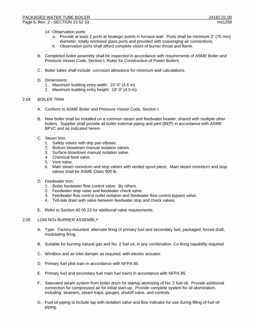
PACKAGED WATER TUBE BOILER 24182.01.00 Page 6, Rev. 2 - SECTION 23 52 33 ms1259
14. Observation ports:
a. Provide at least 2 ports at strategic points in furnace wall. Ports shall be minimum 3” (75 mm) diameter, totally enclosed glass ports and provided with scavenging air connections.
b. Observation ports shall afford complete vision of burner throat and flame.
B. Completed boiler assembly shall be inspected in accordance with requirements of ASME Boiler and Pressure Vessel Code, Section I, Rules for Construction of Power Boilers.
C. Boiler tubes shall include corrosion allowance for minimum wall calculations.
D. Dimensions: 1. Maximum building entry width: 15’-0” (4.5 m). 2. Maximum building entry height: 18’-0” (4.5 m).
2.04 BOILER TRIM
A. Conform to ASME Boiler and Pressure Vessel Code, Section I.
B. New boiler shall be installed on a common steam and feedwater header, shared with multiple other boilers. Supplier shall provide all boiler external piping and joint (BEP) in accordance with ASME BPVC and as indicated herein.
C. Steam trim: 1. Safety valves with drip pan elbows. 2. Bottom blowdown manual isolation valves. 3. Surface blowdown manual isolation valve. 4. Chemical feed valve. 5. Vent valve. 6. Main steam nonreturn and stop valves with vented spool piece. Main steam nonreturn and stop
valves shall be ASME Class 900 lb.
D. Feedwater trim: 1. Boiler feedwater flow control valve: By others. 2. Feedwater stop valve and feedwater check valve. 3. Feedwater flow control outlet isolation and feedwater flow control bypass valve. 4. Tell-tale drain with valve between feedwater stop and check valves.
E. Refer to Section 40 05 23 for additional valve requirements.
2.05 LOW NOx BURNER ASSEMBLY
A. Type: Factory-mounted; alternate firing of primary fuel and secondary fuel, packaged, forced draft, modulating firing.
B. Suitable for burning natural gas and No. 2 fuel oil, in any combination. Co-firing capability required.
C. Windbox and air inlet damper as required, with electric actuator.
D. Primary fuel pilot train in accordance with NFPA 85.
E. Primary fuel and secondary fuel main fuel trains in accordance with NFPA 85.
F. Saturated steam system from boiler drum for startup atomizing of No. 2 fuel oil. Provide additional connection for compressed air for initial start-up. Provide complete system for oil atomization, including strainers, steam traps, gauges, shutoff valve, and controls.
G. Fuel oil piping to include tap with isolation valve and flow indicator for use during filling of fuel oil piping.

24182.01.00 PACKAGED WATER TUBE BOILER ms1259 SECTION 23 52 33 - Page 7, Rev. 3
H. Control or supply tubing: ASTM A213 Type 316 seamless stainless steel.
I. Manufacturer: Coen (or Todd), Natcom, Hamworthy Peabody, Zeeco.
2.06 FLUE GAS RECIRCULATION (FGR) EQUIPMENT
A. FGR ducting from boiler outlet to FD fan inlet with electric-controlled FGR damper. Provide as required to meet specified emissions limits.
2.07 FORCED DRAFT FAN ASSEMBLY
A. Service: Design for required excess air and for static pressure based on losses from air intake to stack outlet, including economizer, at jobsite altitude.
B. Mounted in basement, forced draft fan assembly with airfoil or backwardly inclined wheel on integral steel base. Assembly complete with following components: 1. One inlet silencer to meet 85 dBA at 3' (1 m) in free-field. 2. Expansion joint at fan outlet.
C. Interconnecting ductwork and supports from fan to burner windbox inlet.
D. Margin of 110% design flow rate and 121% design static pressure shall be applied to fan.
E. Design fan and motor for required VFD operation.
F. Manufacturer: Buffalo Forge, Chicago Blower Corp., Howden, Clarage
2.08 ECONOMIZER ASSEMBLY
A. Tube material: ASTM SA-178A.
B. Maximum fins per inch: 5.
C. Economizer shall operate from 0% to 110% without steaming or flue gas from approaching acid dew point temperature. If needed, measures such as bypassing feedwater around portion of economizer heating surface may be used to prevent steaming. When bypassing is used, material and construction shall allow continuous operation in either normal or bypass mode and shall provide for automatic temperature controlled modulation between modes. Accessories required to accomplish bypassing shall be provided including control logic (implemented by others), temperature control valves, temperature sensor, and accessories.
D. Accessories: 1. Breeching from boiler to economizer. 2. Inlet transition with expansion joint. 3. Transition duct from economizer to stack with expansion joint. 4. Draft control damper (if required) with electric actuator to accept 4-20 mA signal from CCS. 5. Steel economizer support structure. 6. Safety relief valve(s). 7. All feedwater pipe downstream of the feedwater stop valve.
E. Design so access for tube inspection can be achieved by access doors.
F. Provide 2” (50 mm) threaded coupling at any low points in breeching and downstream of draft control damper (if required).
G. Gas side connections on economizer: Plate flange-type with drilling for bolt holes for aligning to adjacent components.
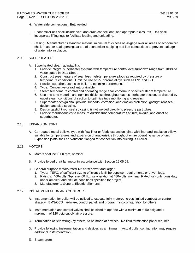
PACKAGED WATER TUBE BOILER 24182.01.00 Page 8, Rev. 2 - SECTION 23 52 33 ms1259
H. Water side connections: Butt welded.
I. Economizer unit shall include vent and drain connections, and appropriate closures. Unit shall incorporate lifting lugs to facilitate loading and unloading.
J. Casing: Manufacturer’s standard material minimum thickness of 20-gage over all areas of economizer shell. Flash or seal openings at top of economizer at piping and flue connections to prevent leakage of water into insulation.
2.09 SUPERHEATER
A. Superheated steam adaptability: 1. Provide integral superheater systems with temperature control over turndown range from 100% to
value stated in Data Sheet. 2. Construct superheaters of seamless high-temperature alloys as required by pressure or
temperature conditions. Limit the use of 9% chrome alloys such as P91 and T91. 3. Position superheaters inside boiler to optimize performance. 4. Type: Convective or radiant, drainable. 5. Steam temperature control and operating range shall conform to specified steam temperature. 6. Use one tube material and nominal thickness throughout each superheater section, as dictated by
outlet steam conditions of section to optimize tube monitoring and repairs. 7. Superheater design shall provide supports, corrosion, and erosion protection, gastight roof seal
design, and side spacing. 8. Design gastight roof seal so casing is not welded directly to pressure part tubes. 9. Provide thermocouples to measure outside tube temperatures at inlet, middle, and outlet of
superheater.
2.10 EXPANSION JOINT
A. Corrugated metal bellows type with flow liner or fabric expansion joints with liner and insulation pillow, suitable for temperatures and expansion characteristics throughout entire operating range of unit. Expansion joints shall be Vanstone flanged for connection into ducting, if circular.
2.11 MOTORS
A. Motors shall be 1800 rpm, nominal.
B. Provide forced draft fan motor in accordance with Section 26 05 09.
C. General purpose motors rated 1/2 horsepower and larger: 1. Type: TEFC, of sufficient size to efficiently fulfill horsepower requirements or driven load. 2. Ratings: 460-volts, 3-phase, 60 Hz, for operation at 480-volts, nominal. Rated for continuous duty
under ambient and altitude conditions specified for project. 3. Manufacturer’s: General Electric, Siemens.
2.12 INSTRUMENTATION AND CONTROLS
A. Instrumentation for boiler will be utilized to execute fully metered, cross-limited combustion control strategy. BMS/CCS hardware, control panel, and programming/configuration by others.
B. Instrumentation and control valves shall be sized to operate with a minimum of 50 psig and a maximum of 120 psig supply air pressure.
C. Termination of field wiring (by others) to be made at devices. No field termination panel required.
D. Provide following instrumentation and devices as a minimum. Actual boiler configuration may require additional instrumentation.
E. Steam drum:

24182.01.00 PACKAGED WATER TUBE BOILER ms1259 SECTION 23 52 33 - Page 9, Rev. 3
1. Three pairs of drum level taps as follows:
a. Pair 1: Differential pressure level transmitter; column assembly for level electrodes. b. Pair 2: Differential pressure level transmitter; bi-color backlit gage sight glass. Provide two (2)
bi-color gage glasses with two valve isolation and flanges so that one can be removed and repaired while the other remains in service.
c. Pair 3: Differential pressure level transmitter. 2. Shunt button for testing low water cutoffs without tripping boiler. 3. Pressure gage with root valve and 2-valve manifold. Locate on same tap as gage pressure
transmitter; capable of being independently isolated. 4. One gage pressure transmitter with root valve and 2-valve manifold. 5. Remote level relay panel:
a. Low-low water cutoff trip relay. b. High-high water cutoff trip relay. c. Relays as required for one remote level indicator.
F. Combustion air: 1. Differential pressure transmitter with manifold and root valve for measurement of combustion air
flow. 2. Low-low flow switch. 3. Thermowell. 4. Temperature element. 5. Windbox pressure transmitter with manifold and root valve. 6. Pressure gage.
G. Boiler feedwater: 1. Thermowell. 2. Temperature assembly: element and thermowell (by others). 3. Connection with root valve for pressure transmitter. Pressure transmitter, instrument tubing, and
2-valve manifold by others. 4. Pressure gage with siphon, block and bleed valve, and root valve. 5. Flow element and transmitter: By others.
H. Steam line: 1. Flow element and transmitter: By others. 2. Pressure gage with 2-valve manifold and root valve. 3. Pressure transmitter with 2-valve manifold and root valve. (by others) 4. Thermowell. 5. Temperature assembly: By others. 6. Steam sampling nozzle with socket-welded isolation valve.
I. Furnace: Pressure transmitter with 2-valve manifold (by others).
J. Continuous blowdown line: 1. Conductivity probe and transmitter: By others. 2. Intermittent and continuous blowdown bypass valves: By others. 3. Intermittent and continuous blowdown control valve: By others.
K. Economizer: 1. Flue side pressure transmitter with 2-valve manifold and root valve. 2. Flue side temperature assembly: Element and thermowell. 3. Thermowells. 4. Feedwater inlet temperature assembly: Element thermowell. 5. Feedwater outlet temperature assembly: Element thermowell.
L. Stack: 1. Oxygen analyzer, indicator, and transmitter complete with calibration station. 2. NOX analyzer, indicator, and transmitter with calibration station. 3. Opacity monitor for fuel oil.

PACKAGED WATER TUBE BOILER 24182.01.00 Page 10, Rev. 2 - SECTION 23 52 33 ms1259
M. Provide local indicating display for transmitters.
N. Impulse tubing: Type 316 seamless stainless steel, 1/2" OD x 0.049" wall, ASTM A213.
O. Control and instrument air supply tubing: ASTM A213 Type 316 seamless stainless steel, 3/8" ID with 0.035" wall.
P. Manufacturers: 1. Pressure:
a. Gages: Perma-Cal. b. Switches: Ashcroft Series Type 400 B-Series. c. Gage transmitters (with manifold): Rosemount Model 3051 series, Yokogawa Model EJX
series, or equal. d. Differential pressure transmitters (with manifold): Rosemount Model 3051 series, Yokogawa
Models EJA series. 2. Temperature:
a. Gages: Ashcroft Model 50-EL-42. b. Gage thermowell: Ashroft Model 75W. c. Switches: Ashcroft Type 400, B-Series. d. Elements:
1) RTD: Rosemount Series 68 with thermowell, or equal. 2) Thermocouple: Rosemount Series 183 Type J with thermowell, or equal.
3. Oxygen analyzers: Oxygen: Yokogawa ZR series. 4. Level:
a. Gage glass and accessories: Simpliport 180. b. Fuel cutout: High and low water level fuel cutout with bypass switch. Bypass switch and
LWCO drain test valve shall be located within view of level gage. c. Remote level:
1) Water column: Electrolev, 10 probes. 2) Relay panel: Electro eye-hye, 10–level control unit. 3) Level indicator: Miniature bi-color.
d. Manufacturer: Clark-Reliance. 5. Gas train shutoff valves: Maxon. 6. Flow:
a. Fuel oil: Micromotion R-series (coriolis) with indicating transmitter. b. Natural gas: Veris Veribar with Rosemount Model 3095 series multi-variable mass flow
transmitter. 7. Pneumatic positioner: Fisher DVC6000. 8. Electric actuators: Beck.
Q. Burner management system (BMS) and flame safety control system: 1. Provide sequence of operations, logic diagrams, and Input/Output listing for programming and
configuration of BMS logic required to satisfy requirements of latest edition of NFPA 85. 2. Conform to NFPA 85. Components shall be UL-listed and FM-approved. 3. Sequential interlocks and emergency shutdown. Sequential interlocks and controls in accordance
with current NFPA requirements. 4. Complete emergency shutdown of unit including interruption of fuel supply for following, but not
limited to, trip conditions: a. Boiler steam pressure high. b. Low water cutoff. c. Auxiliary low water cutoff from probe switch. d. High natural gas pressure. e. Low natural gas pressure. f. Low instrument air pressure. g. Loss of combustion air supply. h. Flame failure.

24182.01.00 PACKAGED WATER TUBE BOILER ms1259 SECTION 23 52 33 - Page 11, Rev. 3
i. High-high water cutoff from probe switch. j. Local emergency trip pushbutton. k. Remote emergency trip pushbutton. l. Critical input/output failure. m. Loss of combustion control system. n. Loss of control power or interlock power.
5. Flame scanners: a. Provide to prove pilot and main flame ignition for both natural gas and No. 2 fuel oil. b. Quantity: 2. c. Type: IR/UV. d. Manufacturer: Fireye or Coen.
2.13 PAINTING
A. Steel items shall receive following surface treatment: 1. SSPC-SP10 commercial blast to 1.5 to 2.0 mils profile depth. 2. Apply manufacturer's standard primer and finish coats to 8 mils minimum DFT on all steel items
except no paint within 3” of edges to be welded.
2.14 SOURCE QUALITY CONTROL
A. Factory cleaning, inspection, and testing: 1. Boiler drums, economizer, superheater, and interconnecting piping shall be flushed out with water
at factory in manner to remove foreign material. Thoroughly dry equipment, install desiccant in boiler drum, then seal connections following cleaning. Boiler shall be delivered to site in rust-free state.
2. Notify Buyer 2 weeks prior to test and make arrangements for Buyer to witness factory tests. 3. Boiler including economizer and superheater shall be individually factory hydrostatically-tested in
accordance with ASME Boiler Code. 4. Furnace casing shall be air tested to 1-1/2 times the working pressure . 5. Major boiler modules including ductwork, expansion bellows, boiler, economizer, and superheater
shall be match-marked to ensure match-up of field connections.
PART 3 EXECUTION
NOT USED

PACKAGED WATER TUBE BOILER 24182.01.00 Page 12, Rev. 2 - SECTION 23 52 33 ms1259
DATA SHEET
PACKAGED WATER TUBE BOILER
Equipment: Water Tube Boiler
Tag No.: Boiler No. LATER
DESCRIPTION UNITS SPEC DATA
VENDOR DATA
Name
Boiler Model Number
Performance
Rated Capacity (minimum) lb/hr 175,000 *
Design Heat Input (primary fuel) MMBtu/hr by Mfg
Heat Release Rate (maximum) Btu/ft3-hr by Mfg
Steam Operating Pressure at Stop Valve Outlet
psig 850 *
Steam Operating Temperature at Stop Valve Outlet
°F 740 *
Control Range for Specified Operating Temperature
% by Mfg
Moisture Carryover (maximum) % 0.5% *
Design Pressure (minimum) psig 975
Design Temperature °F 750
Inlet Air Temperature °F 80
Load % 25 50 75 100
Boiler Efficiencies (Primary Fuel - HHV) % by Mfg
Boiler Efficiencies with Economizer ( Primary Fuel – HHV) (Guaranteed)
83 *
Boiler Efficiencies (Secondary Fuel - HHV) % by Mfg
Boiler Efficiencies with Economizer (Secondary Fuel – HHV) (Guaranteed)
87 *
Emissions Limits: Primary Fuel
25 50 75 100
NOx (primary fuel) (lb/MMBtu) .04/.07 *
CO (primary fuel) (lb/MMBtu) .04/.08 *
SOx (primary fuel) (lb/MMBtu) 0.5 *
Particulate (primary fuel) (lb/MMBtu) 0.2 *
VOC (primary fuel) (lb/MMBtu)
0.005/0.005
*
Emissions Limits: Secondary Fuel
25 50 75 100
NOx (secondary fuel) (lb/MMBtu) .04/.07 *
CO (secondary fuel) (lb/MMBtu) .04/.08 *
SOx (secondary fuel) (lb/MMBtu) 0.5 *
Particulate (secondary fuel) (lb/MMBtu) 0.2 *
VOC (secondary fuel) (lb/MMBtu)
0.005/0.005
*
Flue Gas Recirculation (as applicable) % by Mfg
Feedwater Normal Operating Temperature (Economizer Inlet)
°F 242
Feedwater Normal Operating Pressure (Economizer Inlet)
psig LATER
Feedwater System Design Temperature °F 300
Feedwater System Design Pressure psig 1200
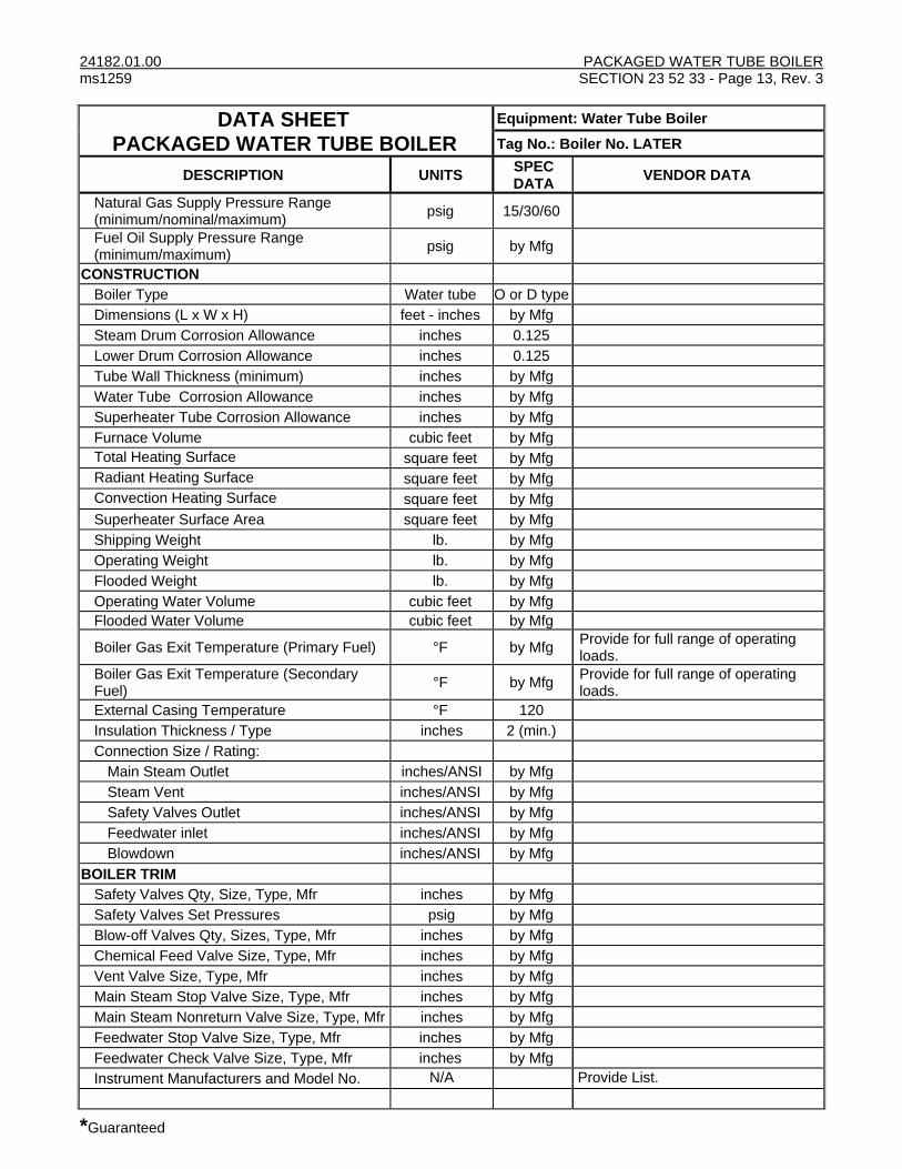
24182.01.00 PACKAGED WATER TUBE BOILER ms1259 SECTION 23 52 33 - Page 13, Rev. 3
*Guaranteed
DATA SHEET
PACKAGED WATER TUBE BOILER
Equipment: Water Tube Boiler
Tag No.: Boiler No. LATER
DESCRIPTION UNITS SPEC DATA
VENDOR DATA
Natural Gas Supply Pressure Range (minimum/nominal/maximum)
psig 15/30/60
Fuel Oil Supply Pressure Range (minimum/maximum)
psig by Mfg
CONSTRUCTION
Boiler Type Water tube O or D type
Dimensions (L x W x H) feet - inches by Mfg
Steam Drum Corrosion Allowance inches 0.125
Lower Drum Corrosion Allowance inches 0.125
Tube Wall Thickness (minimum) inches by Mfg
Water Tube Corrosion Allowance inches by Mfg
Superheater Tube Corrosion Allowance inches by Mfg
Furnace Volume cubic feet by Mfg
Total Heating Surface square feet by Mfg
Radiant Heating Surface square feet by Mfg
Convection Heating Surface square feet by Mfg
Superheater Surface Area square feet by Mfg
Shipping Weight lb. by Mfg
Operating Weight lb. by Mfg
Flooded Weight lb. by Mfg
Operating Water Volume cubic feet by Mfg
Flooded Water Volume cubic feet by Mfg
Boiler Gas Exit Temperature (Primary Fuel) °F by Mfg Provide for full range of operating loads.
Boiler Gas Exit Temperature (Secondary Fuel)
°F by Mfg Provide for full range of operating loads.
External Casing Temperature °F 120
Insulation Thickness / Type inches 2 (min.)
Connection Size / Rating:
Main Steam Outlet inches/ANSI by Mfg
Steam Vent inches/ANSI by Mfg
Safety Valves Outlet inches/ANSI by Mfg
Feedwater inlet inches/ANSI by Mfg
Blowdown inches/ANSI by Mfg
BOILER TRIM
Safety Valves Qty, Size, Type, Mfr inches by Mfg
Safety Valves Set Pressures psig by Mfg
Blow-off Valves Qty, Sizes, Type, Mfr inches by Mfg
Chemical Feed Valve Size, Type, Mfr inches by Mfg
Vent Valve Size, Type, Mfr inches by Mfg
Main Steam Stop Valve Size, Type, Mfr inches by Mfg
Main Steam Nonreturn Valve Size, Type, Mfr inches by Mfg
Feedwater Stop Valve Size, Type, Mfr inches by Mfg
Feedwater Check Valve Size, Type, Mfr inches by Mfg
Instrument Manufacturers and Model No. N/A Provide List.

PACKAGED WATER TUBE BOILER 24182.01.00 Page 14, Rev. 2 - SECTION 23 52 33 ms1259
DATA SHEET
PACKAGED WATER TUBE BOILER
Equipment: Water Tube Boiler
Tag No.: Boiler No. LATER
DESCRIPTION UNITS SPEC DATA
VENDOR DATA
BURNER ASSEMBLY
Manufacturer N/A by Mfg
Primary Fuel N/A Natural Gas
Secondary Fuel N/A No.2 Fuel
Oil
Igniter Manufacturer / Model N/A by Mfg
Turndown (Primary Fuel) N/A 10:1 *
Turndown (Secondary Fuel) N/A 8:1 *
Main Gas Train Piping schedule 40
Main Gas Connection Size / Rating inches/ANSI by Mfg
Main Gas Train Components N/A Provide List.
Pilot Gas Train Piping schedule 80
Pilot Gas Train Components N/A Provide List.
Fuel Oil Train Piping schedule 80
Fuel Oil Connection Size / Rating inches/ANSI by Mfg
Fuel Oil Train Components N/A Provide List.
Atomizing Steam and Air Train Piping schedule 80
Atomizing Steam and Air Train Components N/A Provide List.
Sound Level at Max. Firing Rate (at 3 feet) dBA 85
Burner Management System Manufacturer N/A N/A N/A
Panel Rating NEMA N/A N/A
Instrument Manufacturers and Model No. N/A Provide List.
FORCED DRAFT FAN
Manufacturer N/A by Mfg
Air Flow lb/hr by Mfg
Air Flow ACFM by Mfg
Air Flow SCFM by Mfg
Design Static Head In wg by Mfg
Silencer (at 3 feet) dBA 85
Motor Manufacturer / Model N/A by Mfg
VFD Manufacturer / Model N/A by Mfg
Power horsepower by Mfg
Electrical Requirement volts/phase/Hz by Mfg
rpm at rated load (maximum) rpm 1800
ECONOMIZER
Dimensions (L x W x H) feet - inches by Mfg
Design Pressure Psig by Mfg
Gas Exit Temperature (Primary Fuel) °F by Mfg Provide for full range of operating loads.
Gas Exit Temperature (Secondary Fuel) °F by Mfg Provide for full range of operating loads.
Feedwater Exit Temperature (Primary Fuel) °F by Mfg Provide for full range of operating loads.
Feedwater Exit Temperature (Secondary Fuel)
°F by Mfg Provide for full range of operating loads.
Tube Size and material inches / ASTM by Mfg

24182.01.00 PACKAGED WATER TUBE BOILER ms1259 SECTION 23 52 33 - Page 15, Rev. 3
*Guaranteed
DATA SHEET
PACKAGED WATER TUBE BOILER
Equipment: Water Tube Boiler
Tag No.: Boiler No. LATER
DESCRIPTION UNITS SPEC DATA
VENDOR DATA
No.
Tube Wall Corrosion Allowance inches by Mfg
Fin number/inch; material; height N/A by Mfg
Pressure Drop, waterside psi by Mfg
Pressure Drop, airside psi by Mfg
STACK
Height (from base of boiler) feet 115
Diameter (inside) inches
Material ASTM No. steel
Insulated and lagged N/A Yes/no
Thermometer Manufacturer and Model No. N/A by Mfg
END OF SECTION
1) M. R. Fritz, W. E. Hanno 2) B. A. Pankow

24182.01.00 COMMON WORK RESULTS FOR ELECTRICAL PACKAGED EQUIPMENT ms1259 SECTION 26 05 00 - Page 1
PART 1 GENERAL
1.01 SECTION INCLUDES
A. General electrical requirements for boiler equipment package and services including, but not limited to: 1. Auxiliary power. 2. Factory wiring. 3. Electrical enclosures. 4. Equipment safety grounding. 5. Low voltage fuses and fuse blocks. 6. Control relays and switches. 7. Pushbuttons. 8. Indicating lights. 9. Alarm and trip contacts. 10. Circuit breakers and disconnect switches. 11. Auxiliary power transformers. 12. Nameplates.
1.02 WORK BY OTHERS
A. Equipment foundations and supports.
B. Receiving, unloading and storing.
C. Final placement and assembly.
D. External power, control and grounding connections.
1.03 INFORMATIONAL SUBMITTALS
A. Product Data: 1. Equipment performance curves. 2. List of recommended spare parts required for equipment start-up, commissioning and operation. 3. List of special maintenance tools required for installation and operation of equipment.
1.04 ACTION SUBMITTALS
A. Shop Drawings: 1. Drawing submittal index. 2. Manufacturer’s catalog sheets marked to indicate specific type, model or catalog number of
equipment to be provided. 3. Equipment drawings showing layout of electrical components. 4. Elementary wiring diagrams and schematics for internal wiring and external connections.
Terminal points shall be clearly labeled.
1.05 CLOSEOUT SUBMITTALS
A. Operation and maintenance manuals. Provide at minimum: 1. Complete set of final drawings submitted for review and comment. 2. Product data. 3. Itemized equipment list. 4. General description and technical data. 5. Receiving, storage, installation, and testing instructions. 6. Operating and maintenance procedures. 7. Complete documentation of inspections and tests performed, including logs, curves, and
certificates. Documentation shall note any replacement of equipment or components that failed during testing.

COMMON WORK RESULTS FOR ELECTRICAL PACKAGED EQUIPMENT 24182.01.00 Page 2 - SECTION 26 05 00 ms1259
8. Lubrication recommendations. 9. Warranty information.
1.06 MAINTENANCE MATERIALS
A. Each piece of equipment shall be furnished with special tools as required for installation, maintenance, and dismantling of equipment. 1. Furnish in quantities as necessary to complete work on schedule. 2. Tools shall be new and shall become property of Buyer. 3. Tools and intended use shall be identified in assembly instructions. Tools shall only be used for
their intended purpose.
1.07 QUALITY ASSURANCE
A. Manufacturer of equipment specified shall be recognized in industry for normally supplying this type of equipment and shall be ISO certified.
B. Materials and equipment furnished for permanent installation shall be new, unused, and undamaged.
C. Asbestos not allowed.
D. Parts shall be manufactured to American industry standard sizes and gages to facilitate maintenance and interchangeability. Metric sized components not allowed unless specifically requested and approved.
1.08 DELIVERY, STORAGE, AND HANDLING
A. Pack, ship, handle, and store in accordance with manufacturer’s requirements.
B. Ship equipment completely factory assembled unless physical size, arrangement, configuration, or shipping and handling limitations make this impracticable.
C. Costs associated with sections, accessories, or appurtenances requiring field assembly shall be Contractor’s responsibility.
D. Separately packaged parts and accessories shall be consolidated and shipped together with equipment. Mark each container clearly to identify contents and as belonging with main equipment. 1. Provide individual weatherproof itemized packing slips attached to outside of each container for
contents included. Provide duplicate inside each container. 2. Attach master packing list, covering accessory items for equipment, to main piece of equipment. 3. Mark each container with project identification number for equipment and container number
followed by total number of containers.
E. Equipment shall be suitably protected during shipment, handling, and storage. Damage incurred during shipment shall be repaired at not cost to Buyer.
F. Protect coated surfaces against impact, abrasion, and discoloration.
G. Electrical equipment and insulation systems shall be protected against ingress of moisture. Use space heaters if necessary to protect against moisture.
H. Exposed threads shall be greased and protected.
I. Pipe, tube, and conduit connections shall be closed with rough usage plugs. Seal and tape open ends of piping, tubing, and conduit.
J. Equipment openings shall have covers, and taped to seal equipment.

24182.01.00 COMMON WORK RESULTS FOR ELECTRICAL PACKAGED EQUIPMENT ms1259 SECTION 26 05 00 - Page 3
K. Store materials in clean, dry place. Protect from weather, dirt, water, construction debris, and physical
damage in accordance with manufacture’s instructions.
PART 2 PRODUCTS
2.01 DESIGN REQUIREMENTS
A. Equipment and material furnished shall be suitable for intended service and installation location at project site. Equipment enclosures shall be NEMA 12 rated.
B. If equipment will be installed in or required for hazardous locations, equipment shall be carry appropriate UL-listing and have labeling for class, division, and group designation in accordance with NEC Article 500.
2.02 AUXILIARY POWER
A. Design auxiliary equipment for low voltage service, with electrical power designed to operate from one of nominal electrical power sources as follows and as indicated on Drawings:
Volts System Phase Frequency
480 Ungrounded Delta 3 60
B. Electrical power for ac control and instrumentation equipment: 1. Provide devices required for proper operation and protection of equipment during electrical power
supply and ambient temperature fluctuations specified. 2. Design for continuous operation at any voltage from 85% to 110% of nominal voltage. Dropout
voltage shall be 60% of nominal for relays and 75% for contactors and starters.
2.03 FACTORY WIRING
A. Select cable for electrical and environmental conditions of installation, and suitable for unusual service conditions where encountered. 1. Proper temperature application cable shall be used throughout, but shall be not less than 90ºC
rated. 2. Conductors routed over hinges shall use extra-flexible stranding. 3. Cable insulation shall be rated for maximum service voltage used, but not less than 600 volts. 4. Splices not allowed. 5. Mineral insulation (NEC Type MI), and polyvinyl chloride (PVC) insulation and jacketing (NEC
Types AWM, MTW, TA, TBS, THHN, THHW, THWN, TW, or THW) shall not be utilized.
B. Control panel cabinet and power wiring shall utilize flame retardant cross-linked polyethylene or flame retardant ethylene-propylene rubber insulation meeting requirements of UL 44 for Types MTW. Power wiring shall meet or exceed requirements of UL 44 for Types MTW. 1. Minimum size: No. 16 AWG. 2. Conductors: Annealed bare copper Class B stranding passing IEEE 1202 and UL VW-1 flame
test. a. Single conductor cables shall have moisture resistant, flame retardant ethylene-propylene
rubber insulation with Hypalon jacket. b. Multi-conductor cables shall have moisture resistant, flame retardant cross-linked
polyethylene conductor insulation (XHHW or RHW) and an overall Hypalon jacket c. For extreme ambient conditions (in excess of 70C) use one of following:
1) NEC Type SF-2 silicone rubber insulated cable with braided glass jacket. 2) NEC Type FEP fluorinated ethylene-propylene insulated cable.
C. Instrumentation, thermocouple, and thermocouple extension wire shall use twisted shielded pairs/triads having flame retardant cross-linked polyethylene (XLPE) insulation, and fiberglass insulated jacket. 1. Minimum size: No. 16 AWG (1.0 mm2).

COMMON WORK RESULTS FOR ELECTRICAL PACKAGED EQUIPMENT 24182.01.00 Page 4 - SECTION 26 05 00 ms1259
2. Conductor type:
a. Instrument: Annealed copper Class B stranding. b. Thermocouple: Solid alloy, ANSI MC 96.1.
3. Provide each pair/triad with shield. 4. Shielding shall consist of aluminum-polyester tape and flexible strand tin-coated No.18 AWG (0.75
mm2) copper drain wire. 5. Drain wire for each instrument cable shall be insulated with spaghetti sleeve. One end of shield
wire shall be terminated on grounded terminal. 6. Cables shall pass IEEE 1202 and ICEA 70,000 Btu/Hr vertical tray flame test, and each conductor
shall pass UL VW-1 flame test.
D. Terminations: 1. Conductor terminal connectors shall be insulated, ring tongue, compression type connectors
properly sized for conductor and terminal. a. Connectors shall be constructed of copper and shall be tin-plated. b. Interior surface of connector wire barrel shall be serrated; exterior surface of connector wire
barrel shall be furnished with crimp guides. 2. Non-insulated terminal connectors shall be used for conductors terminated on devices equipped
with individual fitted covers, such as, but not limited to, control switches and lockout relays. 3. Connections requiring disconnect plug and receptacle type devices shall be provided with factory-
terminated conductors on each plug and receptacle. a. Plugs and receptacles shall be factory wired into junction boxes containing terminal blocks for
external connections. b. Conductors on disconnect portion of plug-receptacle assemblies shall be in common jacket.
4. Prior to shipment of equipment, remove temporary wiring installed in factory for equipment testing. 5. Current transformers shall terminate on shorting type terminal blocks. Ship with shorting jumpers
installed.
E. Identification and labeling. 1. Provide conductor identification sleeve on each end of each internal conductor. Mark each sleeve
with opposite end destination identification with nonsmudging, permanent black ink. Sleeves shall be UV-resistant self-adhesive type or PVC, not less than 1/2” (13 mm) long.
2. Permanently label each terminal block, terminal, conductor, relay, breaker, fuse block, and other auxiliary devices to coincide with identification indicated on manufacturer’s drawings.
2.04 ELECTRICAL ENCLOSURES
A. Size junction boxes, pull boxes, and enclosures in accordance with requirements of NEC and rated to a minimum of NEMA 12.
B. Junction boxes and pull boxes 4” (100 mm) trade size or smaller in any dimension shall be galvanized malleable iron, or cast ferrous metal NEMA rated for installed location. Do not use concentric knockouts.
C. Junction boxes, pull boxes, and electrical enclosures 4” (100 mm) trade size and larger in any dimension shall be as follows, unless required otherwise. 1. NEMA rating for electrical enclosures installed in nonhazardous, indoor locations:
a. Dry environmentally controlled area: NEMA 12. b. Corrosive wet or hose-down area: NEMA 4X
2. Construct noncast-metal electrical enclosures from reinforced steel plate capable of supporting devices mounted on or within enclosure without deflection. Steel plate thickness shall conform to UL requirements.
3. Enclosures shall be of adequate strength to support mounted components during shipment and installation.
4. Conduit entrances shall be field drilled.

24182.01.00 COMMON WORK RESULTS FOR ELECTRICAL PACKAGED EQUIPMENT ms1259 SECTION 26 05 00 - Page 5
2.05 EQUIPMENT SAFETY GROUNDING
A. Furnish equipment that is part of integral shipping unit or assembly with bare copper ground conductor extending to central ground connection lug. Lug shall be suitable for field connection to local ground. Electrical equipment shall be considered any device that is energized.
B. Single-point ground connections required for proper operation of electronic equipment shall be insulated from equipment safety ground. Such connections shall be extended, using insulated cable, to single insolated termination point suitable for field connection to appropriate ground system.
C. Conduits that contain power circuits shall have ground conductor installed inside conduit. Ground conductor shall be bonded to equipment or tray or duct ground at both ends.
D. Provide ground bushing on each conduit containing power circuit. Connect ground bushings together inside enclosure and to enclosure ground lug or ground bus. 1. Use No. 8 AWG conductor for ground bushings trade size 1-1/2” (38 mm) and smaller. 2. Ground bushings larger than 1-1/2” (38 mm) shall be sized in accordance with requirements of
NEC, but in no case shall they be smaller than No. 8 AWG.
E. Ground conductor: Uninsulated, Class B standard, round soft drawn uncoated copper as defined in ICEA S-19-81, unless specified otherwise.
F. Hardware: Clamps, bolts, washers, nuts, and other hardware used with grounding conductor shall be copper, copper ally, high copper alloy, or silicon bronze.
2.06 FUSES AND FUSE BLOCKS
A. Modular-type, Class H screw terminal fuse blocks with Bakelite frame and reinforced retaining clips. Blocks shall be similar in construction and by same manufacturer.
B. Slow blow fuses: Bussmann Type MDL or Gould Shawmut Type GDL with ampere ratings of 1/4, 1/2, 1, or 2.
C. Fast acting fuses: Bussmann Type NON or Gould Shawmut Type OT with ampere ratings of 1, 3, 6, 10, 15, 20, or 30.
D. Extremely fast acting fuses: Bussmann Type KAB with ampere ratings of 1, 3, 6, 10, 15, 20, or 30.
2.07 CONTROL RELAYS
A. General service, industrial grade auxiliary relays rated 600-volt.
B. Contacts shall be reversible from N.O. to N.C. in field.
C. Timing relays for critical service: Agastat Series 7000.
2.08 CONTROL SWITCHES
A. Multistage, rotary-type rated 120 volts ac or 125 volts dc, 3 amperes, as required.
B. Handles shall be black, fixed, modern, pistol grip type. Provide engraved black plastic escutcheon plates with targets.
C. Provide with colored LED lamps and nameplates as required.

COMMON WORK RESULTS FOR ELECTRICAL PACKAGED EQUIPMENT 24182.01.00 Page 6 - SECTION 26 05 00 ms1259
2.09 PUSHBUTTONS
A. Standard pushbuttons shall be heavy, industrial-type rated 120 volts ac or 125 volts dc, 3 amperes, as required.
B. Provide with colored LED lamps and nameplates as required.
2.10 INDICATING LIGHTS
A. Status indicating lights shall be high-intensity, cluster, LED-type for panel mounting.
B. Coordinate indicating light colors with indicated conditions as follows. Indicating lights shall be energized when condition exists and shall be de-energized when condition does not exist: 1. Red: Equipment energized: such as motor running, valve open, or breaker closed. 2. Green: Equipment de-energized: such as motor stopped, valve closed, or breaker open. 3. Amber: Equipment abnormality: such as motor trip, breaker trip, or relay trip. 4. White: Monitoring of control power or trip coil: such as lockout relay trip coil monitor or breaker
trip coil monitor. Light is on during normal circuit operation and off during loss of power or loss of coil.
5. Blue: Loss of control power.
2.11 ALARM AND TRIP CONTACTS
A. Alarm contacts for remote annunciation shall be suitable for operation at 120 volts ac and 125 volts dc. Contacts shall be rated at least 0.5-ampere make and break, minimum.
B. Alarm contacts shall be normally closed contacts that open to alarm condition.
C. Trip contacts for remote trip shall be suitable for operation at 125 volts dc and shall be rated 5 amperes make or break, minimum.
D. Alarm and Trip contacts shall be protected from installation location site conditions by providing enclosure.
2.12 CIRCUIT BREAKERS
A. Provide 3-pole, molded-case, separately enclosed circuit breakers of not less than 25 kA interrupting rating at rated voltage. 1. Provide with thermal and instantaneous trip elements. 2. Breakers shall use high-conductivity copper for current carrying parts. Breaker enclosures shall
have NEMA type enclosure as specified.
B. Each breaker shall be manually operated with quick-make, quick-break, and trip-free toggle mechanism. Thermal elements shall withstand sustained overloads and short-circuit currents without injury and without affecting calibration.
C. Circuit breakers shall have "On," "Off," and "Tripped" indication and shall be pad-lockable with 3 padlocks in “On” and “Off” position. 1. Breakers rated over 70 amperes shall be rated 100% and have adjustable electronic trip units. 2. Breakers shall be capable of adding alarm, lockout, shunt trip, and under-voltage as options.
2.13 DISCONNECT SWITCHES
A. Three-pole, nonfusible, heavy-duty, rated 600-volt with continuous current rating as shown on Drawings and as required by load. 1. Type: Either molded-case or blade. 2. Switches shall use high-conductivity copper for current carrying parts.

24182.01.00 COMMON WORK RESULTS FOR ELECTRICAL PACKAGED EQUIPMENT ms1259 SECTION 26 05 00 - Page 7
B. Switches shall be positive, quick-make, and quick-break mechanisms.
1. Switch assembly plus operating handle shall be integral part of enclosure base. 2. Each switch shall have handle whose position is easily recognizable and which can be locked in
“On” and "Off" position with 3 padlocks. "On" and "Off" positions shall be clearly marked.
C. Switches shall be UL-listed and horsepower rated. Where applicable, switches shall have defeatable door interlocks that prevent door from being opened while operating handle is in "On" position.
2.14 AUXILIARY POWER TRANSFORMERS
A. Windings: Copper.
B. Transformers shall be self-air-cooled, dry-type, and enclosed for wiring connection by conduit.
C. NEMA enclosure type protection shall be as specified herein.
D. Transformer shall be capable of at least 150ºC rise above rated site maximum ambient without degrading transformer life.
E. Transformers shall be capable of continuous operation at rated kVA with normal life expectancy as defined in ANSI C57.
F. Sound level shall not exceed NEMA maximum average sound level.
2.15 WIRING DEVICES
A. Standard convenience outlets: Premium, heavy-duty, specification-grade, duplex, 3-wire, grounding, 20-ampere, 125-volt for 120-volt circuits, and rated 250-volts for 240 or 208-volt circuits.
B. Ground fault circuit interrupter (GFI) receptacles: Duplex, 20-ampere, and 125 volts, feed-through type.
2.16 INSTRUMENT IDENTIFICATION
A. Provide stainless steel identification tag on instruments, gages, valves and temperature wells shown on instrument index. Instrument number per buyer supplied instrument numbering system.
B. Rack-mounted instrumentation shall have tag screwed above or below device with stainless steel hardware. Other instrumentation, control valves, valve actuators, gages and temperature wells shall have tags wired on using stainless steel wire.
C. Following information shall be stamped into each identification tag. Numbers/letters shall be minimum of 3/16” (5mm) high. 1. Purchase order number. 2. Instrument span or range. 3. Instrument identification number (as indicated on Drawings or instrument index).
D. Manufacturer: Panduit MDP series, or equal.
2.17 NAMEPLATES
A. Laminated white-over-black plastic such that face is white with black letters, with 1/8” (3 mm) engraved letters securely fastened with minimum of 2 self-tapping, stainless steel screws.
B. Nameplates for hazardous conditions shall be red plastic laminate engraving stock with white core.

COMMON WORK RESULTS FOR ELECTRICAL PACKAGED EQUIPMENT 24182.01.00 Page 8 - SECTION 26 05 00 ms1259
PART 3 EXECUTION
NOT USED END OF SECTION
1) W. E. Hanno 2) L. E. Ingram

24182.01.00 LARGE MOTORS ms1259 SECTION 26 05 09 - Page 1, Rev. 1
PART 1 GENERAL
1.01 SECTION INCLUDES
A. Medium-voltage, 3-phase, induction, squirrel cage electric motors rated 250 hp and larger.
B. Soleplates, motor anchor bolts, and leveling screws.
1.02 WORK BY OTHERS
A. Motor foundations and foundation anchor bolts.
B. Receiving, unloading, and storage of motors.
C. Final placement and assembly.
D. Power, control, and grounding connections.
1.03 INFORMATIONAL SUBMITTALS
A. Submit with Bid: 1. Completed Data Sheets. 2. Contractor shall indicate if forced-feed lubrication or water cooling of bearings is required.
B. Quality assurance data: Certified shop test reports.
1.04 ACTION SUBMITTALS
A. Shop Drawings: 1. Complete and updated Data Sheets. 2. Certified detailed drawings showing dimensions, anchor locations, weight, lifting points, center of
gravity, enclosure construction, and layout of accessories. 3. Interconnection wiring drawings with terminal points clearly labeled. 4. Interface coordination details. 5. Lube oil piping flow diagram as applicable to specific application. 6. Complete dimensional drawings for sliding bases as applicable to specific application.
B. Product Data: 1. List of instruments and accessories, model number, and operating ranges. 2. Motor curves showing starting current and power factor at 80%, 90%, and 100% terminal voltage. 3. Motor torque versus speed curves at 80%, 90%, and 100% voltage. 4. Motor load versus efficiency curves. 5. Motors for use with VFD shall be inverter duty motors. 6. Torque versus speed curve for driven equipment. 7. Motor hot and cold thermal damage curves with motor starting curves, including driven equipment
inertia, based on system characteristics defined in motor data sheets. 8. Bearing and stator temperature alarm and trip limits. 9. Current transformer excitation and ratio correction factor curves for each motor supplied. 10. List of recommended start-up parts, spare parts, and maintenance tools for each type of motor. 11. Recommended long term and short term storage requirements and procedures.
1.05 CLOSEOUT SUBMITTALS
A. Operation and maintenance manuals. Provide at a minimum: 1. General description and technical data. 2. List of instruments and accessories supplied, listing manufacturer, model number, operating
ranges, and equipment tag numbers. 3. Receiving, storage, installation, and testing instructions.
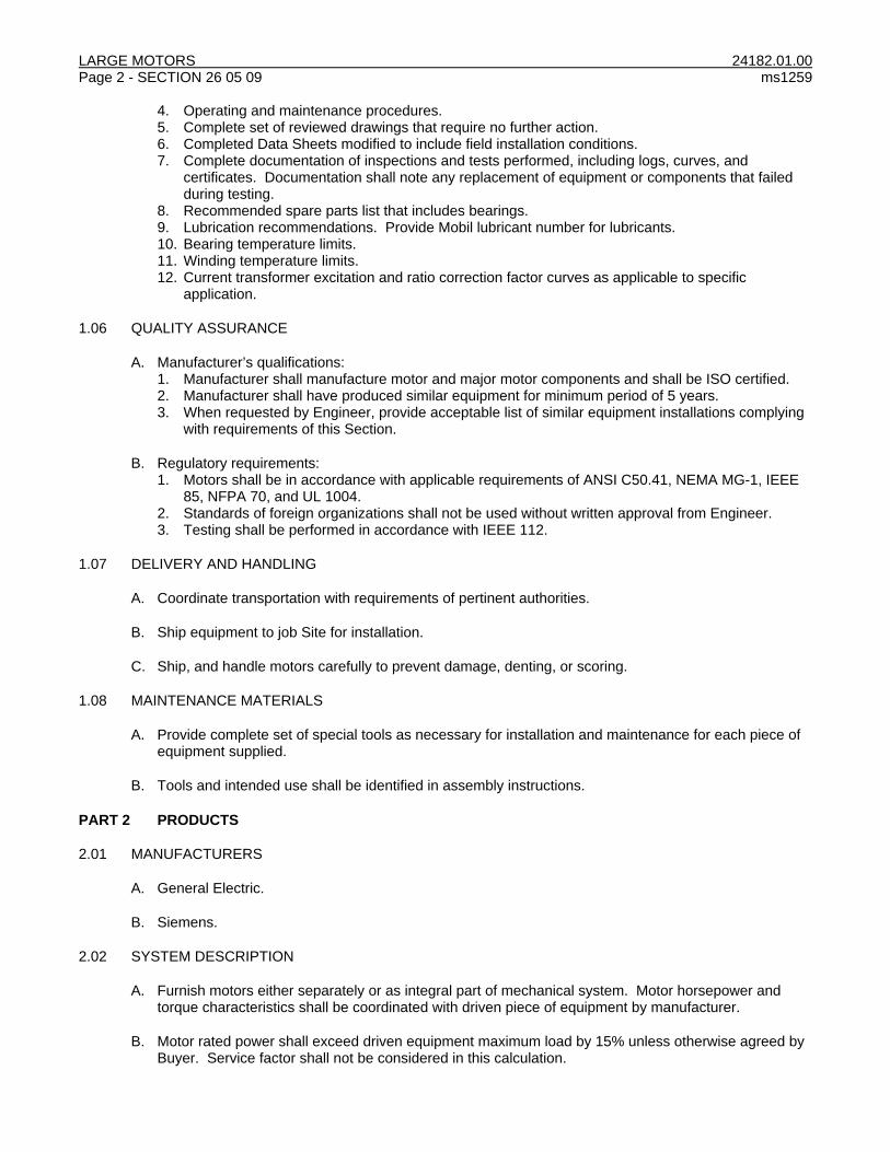
LARGE MOTORS 24182.01.00 Page 2 - SECTION 26 05 09 ms1259
4. Operating and maintenance procedures. 5. Complete set of reviewed drawings that require no further action. 6. Completed Data Sheets modified to include field installation conditions. 7. Complete documentation of inspections and tests performed, including logs, curves, and
certificates. Documentation shall note any replacement of equipment or components that failed during testing.
8. Recommended spare parts list that includes bearings. 9. Lubrication recommendations. Provide Mobil lubricant number for lubricants. 10. Bearing temperature limits. 11. Winding temperature limits. 12. Current transformer excitation and ratio correction factor curves as applicable to specific
application.
1.06 QUALITY ASSURANCE
A. Manufacturer’s qualifications: 1. Manufacturer shall manufacture motor and major motor components and shall be ISO certified. 2. Manufacturer shall have produced similar equipment for minimum period of 5 years. 3. When requested by Engineer, provide acceptable list of similar equipment installations complying
with requirements of this Section.
B. Regulatory requirements: 1. Motors shall be in accordance with applicable requirements of ANSI C50.41, NEMA MG-1, IEEE
85, NFPA 70, and UL 1004. 2. Standards of foreign organizations shall not be used without written approval from Engineer. 3. Testing shall be performed in accordance with IEEE 112.
1.07 DELIVERY AND HANDLING
A. Coordinate transportation with requirements of pertinent authorities.
B. Ship equipment to job Site for installation.
C. Ship, and handle motors carefully to prevent damage, denting, or scoring.
1.08 MAINTENANCE MATERIALS
A. Provide complete set of special tools as necessary for installation and maintenance for each piece of equipment supplied.
B. Tools and intended use shall be identified in assembly instructions.
PART 2 PRODUCTS
2.01 MANUFACTURERS
A. General Electric.
B. Siemens.
2.02 SYSTEM DESCRIPTION
A. Furnish motors either separately or as integral part of mechanical system. Motor horsepower and torque characteristics shall be coordinated with driven piece of equipment by manufacturer.
B. Motor rated power shall exceed driven equipment maximum load by 15% unless otherwise agreed by Buyer. Service factor shall not be considered in this calculation.
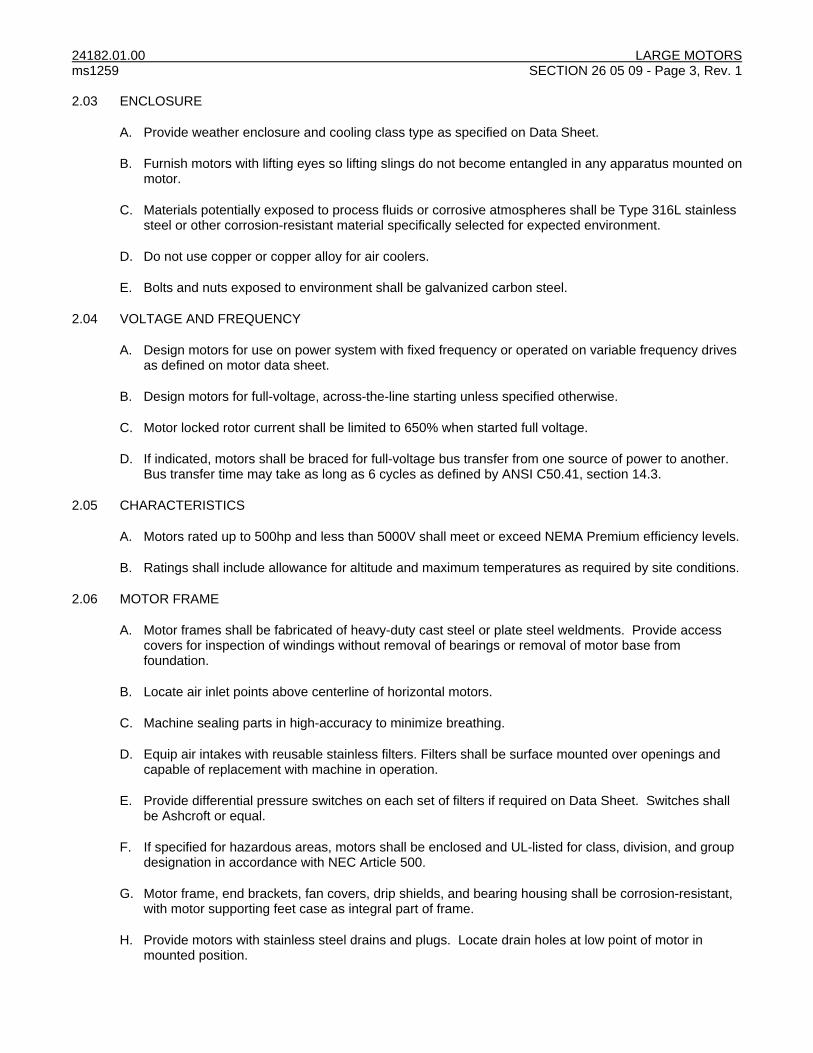
24182.01.00 LARGE MOTORS ms1259 SECTION 26 05 09 - Page 3, Rev. 1 2.03 ENCLOSURE
A. Provide weather enclosure and cooling class type as specified on Data Sheet.
B. Furnish motors with lifting eyes so lifting slings do not become entangled in any apparatus mounted on motor.
C. Materials potentially exposed to process fluids or corrosive atmospheres shall be Type 316L stainless steel or other corrosion-resistant material specifically selected for expected environment.
D. Do not use copper or copper alloy for air coolers.
E. Bolts and nuts exposed to environment shall be galvanized carbon steel.
2.04 VOLTAGE AND FREQUENCY
A. Design motors for use on power system with fixed frequency or operated on variable frequency drives as defined on motor data sheet.
B. Design motors for full-voltage, across-the-line starting unless specified otherwise.
C. Motor locked rotor current shall be limited to 650% when started full voltage.
D. If indicated, motors shall be braced for full-voltage bus transfer from one source of power to another. Bus transfer time may take as long as 6 cycles as defined by ANSI C50.41, section 14.3.
2.05 CHARACTERISTICS
A. Motors rated up to 500hp and less than 5000V shall meet or exceed NEMA Premium efficiency levels.
B. Ratings shall include allowance for altitude and maximum temperatures as required by site conditions.
2.06 MOTOR FRAME
A. Motor frames shall be fabricated of heavy-duty cast steel or plate steel weldments. Provide access covers for inspection of windings without removal of bearings or removal of motor base from foundation.
B. Locate air inlet points above centerline of horizontal motors.
C. Machine sealing parts in high-accuracy to minimize breathing.
D. Equip air intakes with reusable stainless filters. Filters shall be surface mounted over openings and capable of replacement with machine in operation.
E. Provide differential pressure switches on each set of filters if required on Data Sheet. Switches shall be Ashcroft or equal.
F. If specified for hazardous areas, motors shall be enclosed and UL-listed for class, division, and group designation in accordance with NEC Article 500.
G. Motor frame, end brackets, fan covers, drip shields, and bearing housing shall be corrosion-resistant, with motor supporting feet case as integral part of frame.
H. Provide motors with stainless steel drains and plugs. Locate drain holes at low point of motor in mounted position.
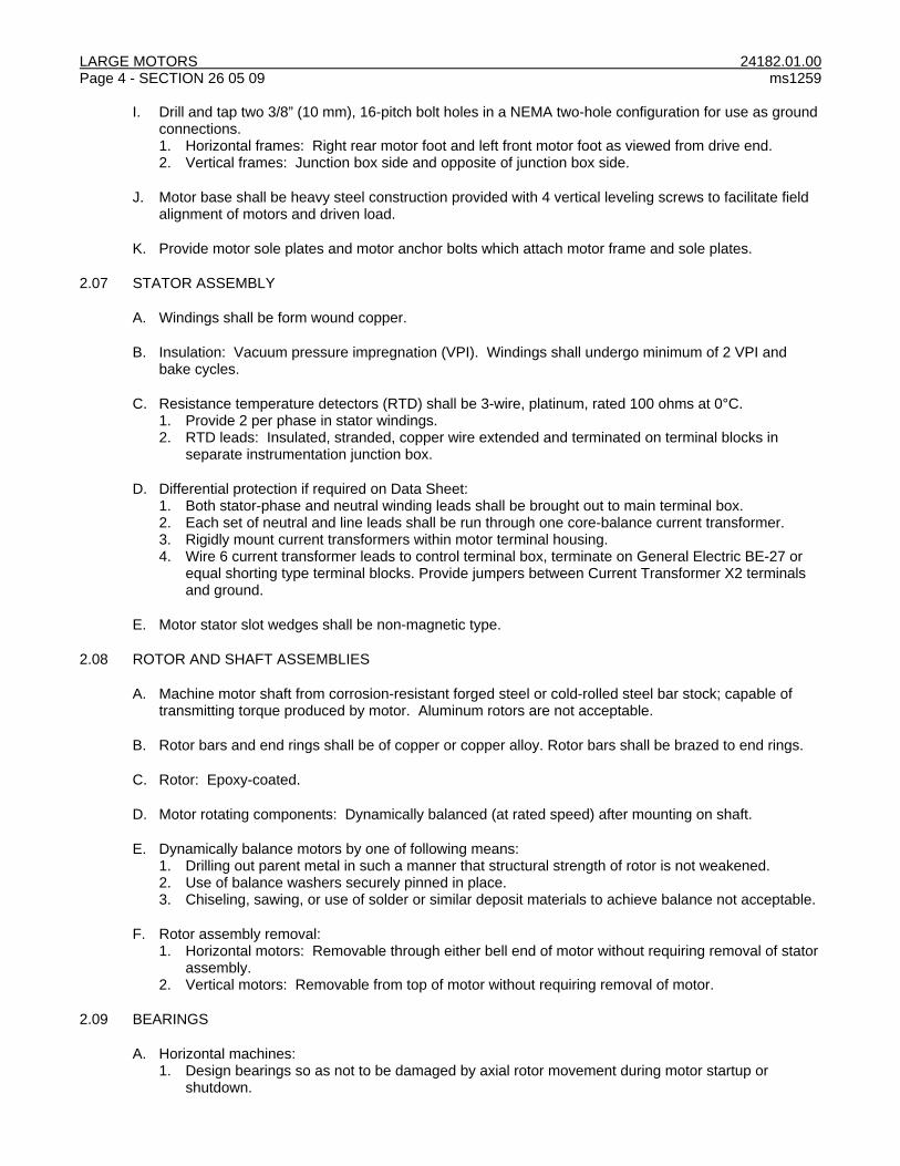
LARGE MOTORS 24182.01.00 Page 4 - SECTION 26 05 09 ms1259
I. Drill and tap two 3/8” (10 mm), 16-pitch bolt holes in a NEMA two-hole configuration for use as ground connections. 1. Horizontal frames: Right rear motor foot and left front motor foot as viewed from drive end. 2. Vertical frames: Junction box side and opposite of junction box side.
J. Motor base shall be heavy steel construction provided with 4 vertical leveling screws to facilitate field alignment of motors and driven load.
K. Provide motor sole plates and motor anchor bolts which attach motor frame and sole plates.
2.07 STATOR ASSEMBLY
A. Windings shall be form wound copper.
B. Insulation: Vacuum pressure impregnation (VPI). Windings shall undergo minimum of 2 VPI and bake cycles.
C. Resistance temperature detectors (RTD) shall be 3-wire, platinum, rated 100 ohms at 0°C. 1. Provide 2 per phase in stator windings. 2. RTD leads: Insulated, stranded, copper wire extended and terminated on terminal blocks in
separate instrumentation junction box.
D. Differential protection if required on Data Sheet: 1. Both stator-phase and neutral winding leads shall be brought out to main terminal box. 2. Each set of neutral and line leads shall be run through one core-balance current transformer. 3. Rigidly mount current transformers within motor terminal housing. 4. Wire 6 current transformer leads to control terminal box, terminate on General Electric BE-27 or
equal shorting type terminal blocks. Provide jumpers between Current Transformer X2 terminals and ground.
E. Motor stator slot wedges shall be non-magnetic type.
2.08 ROTOR AND SHAFT ASSEMBLIES
A. Machine motor shaft from corrosion-resistant forged steel or cold-rolled steel bar stock; capable of transmitting torque produced by motor. Aluminum rotors are not acceptable.
B. Rotor bars and end rings shall be of copper or copper alloy. Rotor bars shall be brazed to end rings.
C. Rotor: Epoxy-coated.
D. Motor rotating components: Dynamically balanced (at rated speed) after mounting on shaft.
E. Dynamically balance motors by one of following means: 1. Drilling out parent metal in such a manner that structural strength of rotor is not weakened. 2. Use of balance washers securely pinned in place. 3. Chiseling, sawing, or use of solder or similar deposit materials to achieve balance not acceptable.
F. Rotor assembly removal: 1. Horizontal motors: Removable through either bell end of motor without requiring removal of stator
assembly. 2. Vertical motors: Removable from top of motor without requiring removal of motor.
2.09 BEARINGS
A. Horizontal machines: 1. Design bearings so as not to be damaged by axial rotor movement during motor startup or
shutdown.

24182.01.00 LARGE MOTORS ms1259 SECTION 26 05 09 - Page 5, Rev. 1
2. Construct and provide bearing and bearing housing with slingers and seals to prevent dirt or moisture from entering motor. Provide interior bearing caps to prevent lubricant from entering motor.
3. Bearing supports: Integral to case as part of motor end bell. Rabbet end bell to stator assembly to ensure proper bearing alignment and air gap spacing.
4. Single shaft extension motors: Insulated non-drive end bearing and ground drive end shaft with shaft brushes.
5. Double shaft extension motors: Insulate non-drive end bearing and drive end shall be grounded by use of shaft grounding brushes.
B. Vertical machines: 1. Design spherical roller thrust bearings to carry 200% of maximum thrust, up and down, which
pump may develop during starting or stopping or while operating at any capacity on rated performance curve.
2. Equip with spark-resistant, non-reversing ratchets, and bolted couplings. 3. Provide water cooling of thrust bearing to maintain bearing temperature below 50C when operated
with driven equipment. 4. Provide Kingsbury-style tilt pad thrust bearing when specified on Data Sheet. 5. Extend guide bearing grease zerk outside of motor and pump base. 6. Provide electrically insulated thrust bearing.
C. All machines: 1. Anti-friction type bearings: Grease-lubricated; minimum rated life L10 with a median life no less
than 50% of L10 life, as defined by AFBMA. Reliability of each bearing shall be greater than 90%. 2. Provide bearings sized to carry imposed loads with minimum design safety factor of 2.0. Provide
bearings and housings that can be removed for examination or replacement without removing rotating element.
3. Bearings shall be vacuum-degassed steel, motor quality. 4. Equip each bearing with three wire platinum RTDs rated 100 ohms at 0°C in quantities specified.
Evenly space multiple RTDs around bearing. Wire and terminate RTD leads on terminal blocks in a common externally mounted instrument junction box.
5. Each bearing shall be tapped for two vibration probes mounted in an X-Y configuration, 90º apart for measuring radial vibration. If vibration probes are specified, factory wire probes to instrumentation junction box.
6. Drill and tap holes for provisions for vibration probes on bearings. 7. Shaft grounding brushes provided shall be 2” (50 mm) wide braided, silver coated, copper shaft
grounding brush with copper grounding conductor routed from brush to motor grounding pad. 8. Sleeve bearing manufacturer: Renk, Kingsbury, or equal.
2.10 LUBRICATION SYSTEM
A. Bearing housing shall have extra large oil reservoirs to serve as settling chambers.
B. Fit each sleeve bearing housing with constant-level, sight-feed oiler marked with proper oil level. Oiler shall be located at extent of motor frame, supported, and piped to bearing housing.
C. Oil system shall have sufficient surge capacity to absorb, without overflowing, oil returned from bearings when motor is stopped.
D. Fit bearing housings with fill and drain openings, slingers, equalizers, vents, and other devices to prevent loss of lubricant.
E. Inlet lines shall be not less than 1/2” (13 mm) diameter.
F. Lubricant for motors requiring forced-feed lubrication shall be supplied from same system as driven equipment. Provide permanent identification plate with lubrication type on equipment.
G. Provide motors with forced lube oil supplied from driven equipment system with oil rings for startup and emergency operation and with dial thermometers to indicate oil temperature.

LARGE MOTORS 24182.01.00 Page 6 - SECTION 26 05 09 ms1259
H. Provide motor with forced lubrication as required by site ambient conditions. Lube oil system shall heat and cool oil to maintain temperature within machine bearing limits.
I. Lube oil tank and piping, if supplied, shall be welded stainless steel construction.
J. Provide system for anti-friction bearings with readily accessible grease inlet and outlet plugs in bearing housings to enable regreasing while motor is in service.
2.11 MOTOR FANS
A. Equip totally enclosed fan cooled motors with externally mounted, nonsparking fan and fan housing. Key fan to motor shaft.
B. Equip weather protected I, II, and open drip proof motors with internal shaft mounted fan.
C. Fan material: Bronze alloy, fiberglass or some other nonsparking material. Aluminum, bronze, copper, or copper alloy not acceptable.
2.12 SPACE HEATERS
A. Mount low surface-temperature space heaters on inside of motor frame.
B. When operating at 110% of rated voltage and ambient temperature, sheath temperature shall not exceed 200°C.
C. Space heaters shall be rated and designed to operate at voltages as specified on Data Sheets.
D. Space heaters shall automatically maintain temperature inside motor at 5°C above dew point.
E. Route space heater power leads to dedicated control terminal box near main terminal box.
2.13 MOTOR TERMINAL BOXES
A. Equip each motor with corrosion-resistant terminal boxes. 1. Provide main terminal box for motor power lead terminations, house surge arrestors and
capacitors as required. 2. Provide separate control terminal box for termination of space heaters leads, current transformer
terminations, filter differential pressure switch etc. 3. Provide separate low-voltage instrument terminal box from main and control boxes. Instrument
terminal box shall house terminations for RTDs, thermocouples, vibration probes, etc. Mount instrument terminal box near control terminal box.
B. Size motor main terminal box to allow for bending radius and stiffness of motor supply cables, and for terminating grounding conductor. At a minimum, size main terminal box at least one size larger than listed in NEMA MG-1.
C. Motor leads shall have brass or stainless steel ferrules embossed with appropriate lead number, or leads imprinted with lead number.
D. Motor lead connections shall be tinned.
E. Main terminal boxes shall have required bushings, standoff insulators, insulation barriers, and hardware for completing line connections.
F. Terminal boxes shall be weatherproof and dusttight, and fitted with neoprene gaskets.
G. Provide motor lead seal and separator gasket between motor frame and terminal box.

24182.01.00 LARGE MOTORS ms1259 SECTION 26 05 09 - Page 7, Rev. 1
H. Provide terminal boxes with removable and gasketed bottom plate for field drilling. Knockouts not acceptable.
I. Motor lead insulation shall be oil-resistant.
J. If specified on Data Sheet, current transformers, surge arrestors, and surge capacitors shall be provided and mounted in main terminal box. Main terminal box shall be increased in size accordingly.
K. Provide NEMA MG-1 Type II motor terminal housing for motors provided with current transformers, surge arrestors, capacitors, and for any machine larger than 1,000 hp.
L. Motor leads: 1. Extra flexible. 2. Rated 125% of motor FLA.
2.14 NOISE AND VIBRATION
A. Equipment shall not exceed sound pressure levels of 85dBA at 3’ (1 m) from equipment surface in accordance with NEMA MG-1.
B. Magnitude of vibration values for running speed and 120 Hz vibrations shall not exceed NEMA-MG1 requirements.
C. Provide vibration monitoring if indicated on Data Sheets. Motors not specified with vibration monitoring, shall be furnished with drilled and tapped bearings and capability to add a vibration monitoring system at later date.
D. Design to keep torsional, rotational, and reed natural frequencies of vibration at least 25% above or below motor rated speed ranges to avoid resonant vibration over operating speed range of motor and driven equipment.
E. When vibration monitoring is required, provide following equipment for each motor: 1. X and Y probes, installed: 2. 2. Thrust probes: 2. 3. Key phaser probe: 1. 4. Manufacturer: Bentley-Nevada, or equal.
2.15 SURGE ARRESTERS AND PROTECTIVE CAPACITORS
A. When specified, provide protective capacitors and MOV-type arresters in motor terminal box. Bus arresters and capacitors to motor terminals.
B. Surge capacitors shall be sealed, nonflammable, and shall not contain polychlorinated biphenyl (PCB) dielectric.
C. Ratings shall correspond to system grounding type as described on Data Sheet.
2.16 IDENTIFICATION AND TAGGING
A. Provide motor with stainless steel nameplates attached with stainless steel screws or pins in locations clearly visible and readable without requiring unsafe condition.
B. Nameplate shall contain standard information in accordance with NEMA MG-1 and following additional information: 1. Serial number and year of manufacture. 2. Type of bearing lubricant and specification number. 3. Arrow indicating direction of rotation for main lead connections. 4. Bearing type and manufacturer’s part number. 5. Current transformer ratings and polarity, if applicable.

LARGE MOTORS 24182.01.00 Page 8 - SECTION 26 05 09 ms1259
6. Use Buyer’s equipment tag identification number.
C. Motor power and space heater circuits may be derived from different sources. Covers of motor terminal boxes containing space heater leads shall be provided with nameplate reading: “DEENERGIZE AND ISOLATE MOTOR AND HEATER CIRCUITS BEFORE REMOVING COVER.”
2.17 VARIABLE SPEED MACHINES
A. Motors defined on Data Sheet for variable speed application shall be inverter duty rated and operated over speed range defined.
B. Provide motors with external cooling fans to force cool machine if operational speed range defined on Data Sheet reduces integral fan performance below required levels to maintain maximum temperature rise.
C. Provide 2” (50 mm) wide braided, silver coated, copper shaft grounding brush with copper grounding conductor routed from brush to motor grounding pad.
D. Electrically insulate both drive end and nondrive end bearings.
2.18 SOURCE QUALITY CONTROL
A. Perform following routine and typical tests complying with NEMA MG-1 and tests specified in Data Sheets: 1. Full load current, locked rotor current, and power measurements. 2. Vibration test in accordance with NEMA MG 1. 3. Locked-rotor current measurement. 4. Power factor at full load, 3/4 load, 1/2 load, and under locked rotor conditions. 5. Percent slip at rated load. 6. Vibration measurements. 7. Machine noise level test in accordance with IEEE 85. 8. Breakdown torque calculation, and pullout and starting torque measurements. 9. Efficiency and power factor measurements for 1/2, 3/4, and full-rated loads in accordance with
IEEE 112, Test Method B. 10. Current balance measurement.
B. In event that motor fails tests, additional tests will be witnessed at discretion of Buyer at no additional cost to Buyer.
C. Test results shall be tabulated, submitted, and accepted by Engineer prior to shipment.
D. Defects and defective equipment revealed or noted during testing will be corrected prior to shipment.
E. Motor test failures shall be reported to Engineer immediately. Motors shall not be repaired without written consent of repair method by Engineer or Buyer. Equipment damaged during testing shall be considered permanently damaged and shall be replaced at suppliers cost with new, not remanufactured or restored, equipment.
PART 3 EXECUTION
NOT USED

24182.01.00 LARGE MOTORS ms1259 SECTION 26 05 09 - Page 9, Rev. 1
DATA SHEETS
LARGE MOTOR
Equipment Name: Boiler #4 FD Fan
Tag No.: FD-4 Rev.
DESCRIPTION UNITS SPEC DATA VENDOR DATA
Motor Manufacturer - By Manufacturer
Motor Catalog No. - By Manufacturer
Location of manufacturer - By Manufacturer
INSTALLATION
Location Indoor/Outdoor
Maximum Ambient Temperature ºC 50
Minimum Ambient Temperature ºC 10
Site Altitude ft 741
Unusual Service Conditions
INSULATION
Minimum Insulation Class (B, F, or H ) - F
Maximum Temperature Rise of Insulation Class (B, F, or H)
- B
SYSTEM REQUIREMENTS
System Voltage kV 4160
Operating Frequency (50 or 60) Hz 60
System Available Short Circuit kA 60
System grounding method Solid /
Impedance / Ungrounded
Solid
Nameplate Voltage kV 4000
Motor Starting Method - FVNR
Full Inverter Duty Rated Y/N Y
Motor Braced for Bus Transfer Y/N N
ELECTRICAL DATA
Service Factor - 1.15
No. of Speeds 1,2,Variable 1
Speed Range 0-100% 0-100%
rpm at Rated Load rpm 1800, nominal
No. of Windings 1,2
MECHANICAL FEATURES
Protective Enclosure IP Code (NEMA MG-1 Part 5) IP IP 44/54 (TEFC)
Method of Cooling IC Code (NEMA MG-1 Part 6) IC IC 411
Maximum Motor Terminal Connection Size kcmil LATER
NEMA Frame Designation - By Manufacturer
Inertia constant of motor. WR^2 lb-ft^2 By Manufacturer
Inertia constant of driven equipment and couplings. WR^2
lb-ft^2 By Manufacturer
Rated Shaft Output Hp By Manufacturer
Driven Load (maximum) Hp By Manufacturer
Sound Level at Full Load (3’ distance) dBA 85 max.
Bearing Type: - By Manufacturer
Drive End By Manufacturer
Non-Drive End - By Manufacturer
Lube Oil System Y/N By Manufacturer

LARGE MOTORS 24182.01.00 Page 10 - SECTION 26 05 09 ms1259
DATA SHEETS
LARGE MOTOR
Equipment Name: Boiler #4 FD Fan
Tag No.: FD-4 Rev.
DESCRIPTION UNITS SPEC DATA VENDOR DATA
Motor Space Heater:
Rated Voltage V 240
Operating Voltage V 120
Wattage W By Manufacturer
Weight Lb By Manufacturer
RTDs
Bearing:
RTD Type - 100 ohm Platinum
Number of Sensors Qty 1 for each bearing
Maximum Temperature To Trip °C By Manufacturer
Stator:
RTD Type - 100 ohm Platinum
Number of Sensors Qty 2 per phase
Maximum Temperature To Trip ºC By Manufacturer
ACCESSORIES
Differential Pressure Switches on Air Filters Y/N N
Surge Capacitor: Y/N N
Capacitor Voltage Rating kV N
Capacitor Rating per pole F N
Surge Arrester: Y/N Y
Surge Arrester Voltage Class kV By Manufacturer
Surge Arrester MCOV kV By Manufacturer
Vibration Monitoring System Y/N Y
Differential Protection: Y/N N
Number Per Phase Qty N/A
CT Ratio A/A N/A
Accuracy Class N/A
SPECIAL REQUIREMENTS
END OF SECTION
1) G. G. Gardner 2) L. E. Ingram

24182.01.00 MEDIUM-VOLTAGE VARIABLE FREQUENCY DRIVES ms1259 SECTION 26 18 39-13 - Page 1
PART 1 GENERAL
1.01 SECTION INCLUDES
A. 12-pulse, medium-voltage variable frequency drive (VFD) including input transformer for drive motor.
1.02 WORK BY OTHERS
A. Power feed cables from motor starter to VFD input transformers.
B. Cabling from VFD output terminals to motor(s).
C. Water connections for drive water-cooling if specified.
D. Drive installation.
1.03 INFORMATIONAL SUBMITTALS
A. Symbols and drawings shall conform to ANSI Y32.2/IEEE 315/CSA Z99.
B. Submittals shall be in English language.
C. Submit with Bid: 1. Completed Data Sheets. 2. Submittal schedule. 3. Special requirements for driven motor. 4. Complete list of equipment proposed including manufacturer, model numbers, and description. 5. Completed Data Sheets 6. Complete data and listing of special equipment required for operation and maintenance of VFD. 7. Complete drive transformer data. 8. Recommended spare parts list with pricing. 9. Plots of typical efficiency vs. speed and torque curves. 10. Harmonic data:
a. Information to demonstrate that harmonic currents generated by drives will not cause power distribution system of generation station to experience harmonic distortion exceeding limits recommended by IEEE Standard 519.
b. Harmonic current distortion at point of common coupling (PCC) shall not exceed limits listed in Table 10.3 of IEEE Standard 519.
c. PCC shall be defined as point of termination of power cable at 4,160-volt motor starter. d. Total harmonic distortion (THD) at each PCC shall not exceed 5% THD limit recommended for
General Systems as listed in Table 10.2 of IEEE Standard 519. 11. Provide harmonic analysis calculations specific to this installation showing total harmonic voltage
and current distortion at PCC. Describe product features and equipment furnished to meet harmonic distortion requirements.
12. Mean Time to Failure data. 13. Special motor requirements for use with VFD. 14. Copy of standard testing procedures for drives. 15. Copies of warranty.
D. Product Data 1. Recommended list of “start up” and “running” spare parts. 2. Instruction manuals for operation and maintenance of VFDs.
E. Quality assurance data: 1. Certified factory test data and results after completion of factory testing. 2. Certified production test reports. 3. Test reports for previous design, and documentation showing previous design ratings and
configurations.

MEDIUM-VOLTAGE VARIABLE FREQUENCY DRIVES 24182.01.00 Page 2 - SECTION 26 18 39-13 ms1259
1.04 ACTION SUBMITTALS
A. Product Data Information as Engineer may request.
B. Shop Drawings: 1. Certified outline and general arrangement, assembly and installation drawings including front
view, dimensions, floor plan, and weight. 2. Certified drawings of cable termination compartments showing preferred locations for conduit
entry/exit locations and indicating space available for cable terminations. 3. Elementary diagrams (3-line diagrams) of complete VFD system showing terminal block
terminations, device terminal numbers and internal diagrams. 4. Schematic control diagrams. 5. Complete wiring diagrams showing connections of all component devices and equipment. 6. Nameplate drawing. 7. Certified complete and accurate Data Sheets.
1.05 CLOSEOUT SUBMITTALS
A. Operation and maintenance manuals. Provide at a minimum: 1. General description and technical data. 2. Receiving, storage, installation, and testing instructions. 3. Operating and maintenance procedures. 4. Complete set of final drawings. 5. Complete documentation of inspections and tests performed, including logs, curves, and
certificates. Documentation shall note replacement of equipment or components that failed during testing.
6. Spare parts lists. 7. Installation field reports. 8. Data sheets updated to reflect field installation conditions.
1.06 QUALITY ASSURANCE
A. Manufacturer’s qualifications: 1. Minimum 10 years experience manufacturing medium-voltage VFDs of size specified. 2. ISO 9001 certified. 3. When requested by Engineer, provide acceptable list of similar equipment installations complying
with requirements of this specification.
B. Regulatory requirements: 1. Design and manufacture VFD and related equipment in accordance with applicable standards of
NEMA, UL, NFPA, IEEE and ANSI. 2. Printed circuit boards shall be completely tested and burned-in in accordance with UL 347A before
being assembled into completed VFD.
C. Test completed drive for at least 3 hours with induction motor connected.
D. Design drive to provide 50,000 hours mean time between failures (MTBF) when specified preventative maintenance is performed.
1.07 DELIVERY, STORAGE, AND HANDLING
A. During delivery and storage, handle equipment to prevent damage, denting, or scoring.
B. Store equipment and components in clean, dry place. Protect from weather, dirt, water, construction debris, and physical damage in accordance with manufacturer’s instructions.

24182.01.00 MEDIUM-VOLTAGE VARIABLE FREQUENCY DRIVES ms1259 SECTION 26 18 39-13 - Page 3
1.08 WARRANTY
A. Provide manufacturer’s standard warranty on all parts, labor, materials and equipment associated with VFDs provided. Warranty shall include travel time and expenses.
PART 2 PRODUCTS
2.01 MANUFACTURERS
A. ABB.
B. Allen-Bradley.
2.02 SYSTEM DESCRIPTION
A. If necessary, equip VFD with input and output filters to limit harmonic distortion to specified levels.
B. VFD shall convert incoming fixed frequency 3-phase ac power into variable frequency and voltage for controlling speed of 3-phase ac motors.
C. Motor current shall closely approximate a sine wave.
D. Motor voltage shall be varied with frequency to maintain desired motor magnetization current suitable for eliminating need for motor derating.
2.03 DESIGN REQUIREMENTS
A. Determine required equipment from one-line diagram.
B. Incoming and outgoing power connections to VFD isolation transformers: See Data Sheets.
C. Incoming power connections to VFD: See Data Sheets.
D. VFD input isolation transformer shall be suitable for mounting on a concrete pad. Transformer shall be oil filled and suitable for operation in ambient conditions specified for site.
E. VFD equipment shall be complete, operable and installed at specified location. Equipment shall include required accessories. All like equipment shall be interchangeable.
F. Environmental requirements: 1. Ambient conditions: See Data Sheets. 2. Design equipment in accordance with the relevant sections of the most recent local Building Code.
2.04 EQUIPMENT
A. VFDs shall be a pulse width modulated (PWM) ac to ac converter with internally mounted filter providing waveform with less than 2% total harmonic voltage distortion at input terminals of motor.
B. Provide VFD with integral fuseless power circuit protection system. Fuseless protection shall include having power switches disconnect all power circuitry from rectifier within 25 microseconds if fault occurs anywhere from dc filter and inverter to motor. Dc link fuses not acceptable.
C. Noise level: Less than 85 dB(A), ± 3dB(A) at 3’ (1 m).
D. Waveform and filtering: 1. Output waveform filter shall be actively controlled and have low-pass frequency well below lowest
inverter switching frequency.

MEDIUM-VOLTAGE VARIABLE FREQUENCY DRIVES 24182.01.00 Page 4 - SECTION 26 18 39-13 ms1259
2. Filter shall be contained within drive enclosure. Output waveform switching transients and
harmonic content shall have negligible contribution to motor heating, acoustical noise in motor, torsional stress in power train, motor bearing currents, and common mode motor insulation voltage.
3. Minimize motor cable voltage reflections and resulting restrictions on motor cable length. 4. High-quality sinusoidal output voltage waveform with less than 2% THD shall be suitable for use
with new or existing standard squirrel cage motors with 1.0 service factor and standard medium voltage insulation.
E. Ratings: 1. VFD shall be rated to operate from 6-phase power as supplied from drive isolation transformer if
required.. 2. Rectifier:
a. VFD shall employ 12-pulse diode rectifier to minimize input line harmonic distortion and operate at input power displacement of 0.97 at all speeds and loads.
b. 24-pulse rectifier shall be used if 12-pulse rectifier is not sufficient to ensure compliance with IEEE 519 in specific installation conditions of station.
3. Efficiency of VFD, exclusive of motor and isolation transformer, shall be 96% or better at full speed and rated load.
4. Output voltage and current ratings shall match adjustable frequency operating requirements of standard 4, 000-volt, 3 phase, 60 Hz NEMA Design B motors.
5. Overload current capacity: 110% of rated current for 1 minute out of 10 minutes. 6. Maximum output frequency shall be a parameter adjustable between 0 and 66Hz. 7. PWM switching pattern shall be continually adjusted to provide optimum motor flux.
F. Control functions and adjustments: 1. User-entered data and parameters shall be held in nonvolatile memory. 2. Start-up data entries: Motor nameplate power, speed, voltage, frequency current and power
factor. 3. Motor parameter ID function shall automatically define motor equivalent circuit used by VFD. 4. Provide PID speed loop regulator with automatic tuning function and manual adjustments. 5. Provide selection of 5 preprogrammed application macro parameter sets to minimize number of
different parameters to be set during start-up. 6. Start/stop control functions: 2 or 3 wire start/stop, coast/ramp, and stop selections. 7. Automatic reset shall attempt to restart drive after undervoltage condition. 8. Accelerate/decelerate functions: 2 sets of ramp time adjustments comprising of linear and 3
S-curve ramp selections. 9. Speed control functions:
a. Adjustable minimum/maximum speed and/or frequency limits. b. Selection of up to 7 preset speed settings or external speed control. c. 5 sets of critical speed lockout adjustments. d. Built-in PID controller to control process variable such as pressure, flow, or fluid level. e. Mathematical speed reference processing functions shall include addition, subtraction and
multiplication of 2 analog inputs and automatic selection of larger or smaller of 2 inputs. 10. Output control functions:
a. Flux optimization by providing optimum magnetic flux for any given speed/torque operating point.
b. Current and torque limit adjustments to limit maximum VFD output current and maximum torque produced by motor.
c. Torque regulated operating mode with adjustable torque ramp up/down and speed limits.
G. Static and dynamic performance: 1. Open loop static speed regulation: 0.1 to 0.3% (10% of motor slip). 2. Torque:
a. Drive shall be capable of developing 100% torque at zero speed. b. Torque response time: 10 milliseconds or less. c. In torque regulating mode, torque regulating accuracy shall be 4% or less.

24182.01.00 MEDIUM-VOLTAGE VARIABLE FREQUENCY DRIVES ms1259 SECTION 26 18 39-13 - Page 5
H. Operator control panel: 1. Equip each VFD with front-mounted operator panel consisting of either a backlit LCD or LED
alphanumeric display and keypad with keys for run/stop, increase/decrease, local/remote, menu navigation, and parameter select/save.
2. Control panel shall include feature for uploading parameter settings to control panel memory and downloading from control panel to same or another drive.
3. During normal operation, speed reference, run/stop and local/remote status shall be displayed. 4. At least 3 additional Buyer-selectable analog values shall be available for display including, as a
minimum: a. Motor speed. b. Output frequency, voltage, current and torque. c. Input voltage, power and kilowatt-hours. d. Cooling air or water temperature and dc bus voltage. e. Status of discrete inputs and outputs. f. Values of analog input and output signals. g. Values of PID controller reference, feedback and error signals.
5. Provide password protection to allow security against unauthorized access.
I. Control system interface: 1. Provide inputs and outputs to interface with control system as identified on Data Sheets. 2. I/O points, minimum:
a. 8 analog inputs: 1) 4-20mA, analog signal processing functions shall include scaling adjustments, adjustable
filtering and signal inversions. 2) Analog signal input functions shall include speed reference signals, process variable
feedback signals, and motor temperature monitoring signals. 3) Upon loss of speed reference signal, drive shall be programmable to stop and display
fault message and run at preset speed. b. 16 discrete inputs:
1) 125-volt dc. 2) 6 independently programmable. 3) Run/stop.
c. 4 analog outputs: 4-20 mA, independently programmable to provide signals proportional to output speed, frequency, voltage, current, and power.
d. 12 relay contact outputs: 1) Rated to switch 2 amperes at 120-volt ac. 2) Function selections: Ready, running, alarm and trip indications. 3) General and specific warning fault indications shall be available. 4) Adjustable supervision limit indications shall be available to indicate programmed values
of operating speed, speed reference, current, torque and PID feedback.
J. Provide one RJ45 Ethernet port for remote communication.
K. Protective functions: 1. For each programmed warning and fault protection function, drive shall display message in
complete English. 2. At least 40 most recent fault messages shall be stored in drive fault history. 3. Input short circuit, ground fault, and input phase loss. 4. Input overvoltage at 130% of maximum rated or undervoltage at 65% of minimum rated and input
phase loss. 5. Provide output short circuit and ground fault protection in accordance with UL 508C. Motor phase
loss protection shall be provided. 6. Drive shall provide electronic motor overload protection qualified in accordance with UL 508C. 7. Dc bus overvoltage at 130% of maximum rated or undervoltage at 65% of minimum rated. 8. Stall protection: Programmable to provide warning or stop drive after motor has operated above
programmed torque level for programmed time limit. 9. Underload protection: Programmable to provide warning or stop drive after motor has operated
below selected underload curve for programmed time limit.

MEDIUM-VOLTAGE VARIABLE FREQUENCY DRIVES 24182.01.00 Page 6 - SECTION 26 18 39-13 ms1259
10. Provide input terminals for connecting 4-20 mA signals to drive protective monitoring circuitry from
3 motor 100 Ohm, platinum winding RTDs.
L. Wiring: Conform to Section 26 05 00. Wiring for external connections by Buyer shall be terminated on terminal blocks, General Electric Type EB-25, or equal.
2.05 ENCLOSURE
A. Type: NEMA 12 minimum.
B. Doors shall include electromechanical interlocking system with safety switch and electrical interlocks from main breaker.
C. Whenever doors are open, safety ground switch shall connect plus, minus, and neutral dc buses to ground to ensure stored energy is discharged.
2.06 WATER COOLING
A. Redundant full capacity pumps with automatic throw-over.
B. Coolant storage reservoir with level indication, low-level alarm and low-level trip contact.
C. Cooling water shall be deionized water.
D. Coolant deionizer with isolation valves, where deionizing cartridge can be changed without shutting down drive.
E. Drain valves to completely drain cooling system.
F. Necessary pressure and temperature alarm and fault trip switches and monitoring devices.
G. Provide local floor drain and dike to contain all water to VFD area.
2.07 IDENTIFICATION AND TAGGING
A. Securely attach nameplates with self-tapping stainless steel screws. Adhesive nameplates not acceptable.
B. Lettering shall be black on white background.
2.08 PAINTS AND FINISHES
A. Finish shall be manufacturer’s standard.
B. Provide two 1-pint spray cans of enamel for touch up.
PART 3 EXECUTION
3.01 MANUFACTURER’S FIELD SERVICES
A. Factory-trained application engineering and service support representative who is thoroughly versed in VFD shall be on-site for 1 week during commissioning.
B. Buyer shall have option of retaining services of manufacturer’s service representative for an additional period of time at rate furnished with Bid.

24182.01.00 MEDIUM-VOLTAGE VARIABLE FREQUENCY DRIVES ms1259 SECTION 26 18 39-13 - Page 7
DATA SHEETS
MEDIUM VOLTAGE VFD
Equipment Name: Boiler #4 FD Fan
Tag No.: FD-4 REV. #
DESCRIPTION UNITS/
OPTIONS SPEC DATA VENDOR DATA
Manufacturer N/A
Catalog/Serial No. N/A
Drive Characteristics:
Nominal Operating Voltage V 4160
Insulation Levels V BIL 60,000
Rectifier Type 12, 24 pulse 24
Ambient Temperature Range °F, °C 50
System Frequency Hz 60
Specific local Building Code and specific relevant sections used in equipment design.
--- By Manufacturer
Motor Data:
Motor Nameplate Voltage V 4000
Motor Nameplate Horsepower hp 500
Motor Service Factor 1, 1.15, etc. 1.15
Full Load Amps A
Insulation (NEMA / NEMA Rise) X / x °C F / B
Enclosure:
NEMA Rating 1,12,3R, etc. 12
Dimensions L x W x H By Manufacturer
Weight Lb. By Manufacturer
Cable Entry Top/Bottom Top
Cable Exit Top/Bottom Top
Drive Input Transformer:
Oil Filled (Preferred) Y/N By Manufacturer
Dry Type (Alternate Only) Y/N By Manufacturer
High Voltage Rating V By Manufacturer
Low Voltage Rating V By Manufacturer
Capacity Rating kVA By Manufacturer
K Factor --- By Manufacturer
Incoming Cable Entrance Top/Bottom
Outgoing Cable Exit Top/Bottom
Accessories:
Cooling Method Air/Water Air
Input Filter Yes/No Yes
Output Filter Yes/No Yes
Special Accessories Required Yes/No No
Control System:
Control System Type DCS/PLC DCS
Control System Interface Required Yes/No
Delivery Schedule:
Total No. of Weeks from Award of Contract, f.o.b.job site
wks By Manufacturer
Submittal of Review Drawings After Award of Contract
wks By Manufacturer
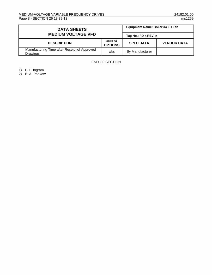
MEDIUM-VOLTAGE VARIABLE FREQUENCY DRIVES 24182.01.00 Page 8 - SECTION 26 18 39-13 ms1259
DATA SHEETS
MEDIUM VOLTAGE VFD
Equipment Name: Boiler #4 FD Fan
Tag No.: FD-4 REV. #
DESCRIPTION UNITS/
OPTIONS SPEC DATA VENDOR DATA
Manufacturing Time after Receipt of Approved Drawings
wks By Manufacturer
END OF SECTION 1) L. E. Ingram 2) B. A. Pankow

24182.01.00 GENERAL DUTY PROCESS VALVES AND ACCESSORIES ms1259 SECTION 40 05 23 - Page 1, Rev. 2
PART 1 GENERAL
1.01 SECTION INCLUDES
A. Valves shown in Valve Schedule.
B. Valves including: 1. Vent and drain valves for equipment furnished under this Contract. 2. Piping high point vents and low point drains. 3. Connections to metering instruments and controls including pressure gages, transmitters,
controllers, traps, and appurtenances required for proper functioning of instruments and controls. 4. Temporary valves and accessories required for placing equipment into initial service. 5. Valves inherent to operation or protection of equipment furnished under this Contract.
C. Accessories.
1.02 RELATED REQUIREMENTS
A. Section 23 52 33 – Packaged Water Tube Boilers.
1.03 ACTION SUBMITTALS
A. Shop Drawings: 1. Certified drawings for each valve. As a minimum, Drawings shall contain:
a. Valve tag numbers. Using Buyer’s valve tagging nomenclature. b. Materials of construction. c. Valve end-to-end and envelope dimensions with operators. d. Valve weight including operator if applicable. e. Weld end preparation details. f. Operator information. g. Special features such as vacuum service, locking device, limit switches, etc. h. Design conditions.
2. Wiring diagrams for field installation of components. 3. Valve list for all valves provided by contract. Valve tagging scheme will be provided by Buyer.
1.04 CLOSEOUT SUBMITTALS
A. Operation and maintenance data. Refer to Section 01 78 23.
1.05 QUALITY ASSURANCE
A. Valves shall be of same manufacturer for each class of piping and insofar as practicable for entire Project.
B. Design and construct ferrous valves in accordance with ASME B16.10 and ASME B16.34.
C. Valves located in boiler code piping shall be constructed in accordance with ASME Boiler and Pressure Vessel Code.
D. Valves shall be stamped with 100ºF (38°C) rating that meets or exceeds specified hydrostatic shell and closure test pressures.
1.06 DELIVERY, STORAGE, AND HANDLING
A. Preparation for shipment: 1. Protect internal parts against rust and corrosion. 2. Protect threads, flange faces, grooves, and weld ends.
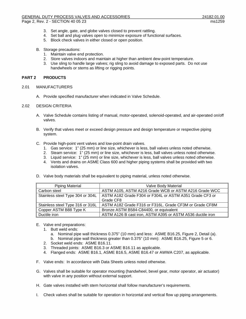
GENERAL DUTY PROCESS VALVES AND ACCESSORIES 24182.01.00 Page 2, Rev. 2 - SECTION 40 05 23 ms1259
3. Set angle, gate, and globe valves closed to prevent rattling. 4. Set ball and plug valves open to minimize exposure of functional surfaces. 5. Block check valves in either closed or open position.
B. Storage precautions: 1. Maintain valve end protection. 2. Store valves indoors and maintain at higher than ambient dew-point temperature. 3. Use sling to handle large valves; rig sling to avoid damage to exposed parts. Do not use
handwheels or stems as lifting or rigging points.
PART 2 PRODUCTS
2.01 MANUFACTURERS
A. Provide specified manufacturer when indicated in Valve Schedule.
2.02 DESIGN CRITERIA
A. Valve Schedule contains listing of manual, motor-operated, solenoid-operated, and air-operated on/off valves.
B. Verify that valves meet or exceed design pressure and design temperature or respective piping system.
C. Provide high-point vent valves and low-point drain valves. 1. Gas service: 1” (25 mm) or line size, whichever is less, ball valves unless noted otherwise. 2. Steam service: 1” (25 mm) or line size, whichever is less, ball valves unless noted otherwise. 3. Liquid service: 1” (25 mm) or line size, whichever is less, ball valves unless noted otherwise. 4. Vents and drains on ASME Class 600 and higher piping systems shall be provided with two
isolation valves.
D. Valve body materials shall be equivalent to piping material, unless noted otherwise.
Piping Material Valve Body Material
Carbon steel ASTM A105, ASTM A216 Grade WCB or ASTM A216 Grade WCC
Stainless steel Type 304 or 304L ASTM A182 Grade F304 or F304L or ASTM A351 Grade CF3 or Grade CF8
Stainless steel Type 316 or 316L ASTM A182 Grade F316 or F316L. Grade CF3M or Grade CF8M
Copper ASTM B88 Type K Bronze ASTM B584-C84400, or equivalent
Ductile iron ASTM A126 B cast iron, ASTM A395 or ASTM A536 ductile iron
E. Valve end preparations: 1. Butt weld ends:
a. Nominal pipe wall thickness 0.375” (10 mm) and less: ASME B16.25, Figure 2, Detail (a). b. Nominal pipe wall thickness greater than 0.375” (10 mm): ASME B16.25, Figure 5 or 6.
2. Socket weld ends: ASME B16.11. 3. Threaded joints: ASME B16.3 or ASME B16.11 as applicable. 4. Flanged ends: ASME B16.1, ASME B16.5, ASME B16.47 or AWWA C207, as applicable.
F. Valve ends: In accordance with Data Sheets unless noted otherwise.
G. Valves shall be suitable for operator mounting (handwheel, bevel gear, motor operator, air actuator) with valve in any position without external support.
H. Gate valves installed with stem horizontal shall follow manufacturer’s requirements.
I. Check valves shall be suitable for operation in horizontal and vertical flow up piping arrangements.

24182.01.00 GENERAL DUTY PROCESS VALVES AND ACCESSORIES ms1259 SECTION 40 05 23 - Page 3, Rev. 2
J. For gage cocks, use ball valves if practicable.
K. For plug valves, use ball valves if practicable. Check local codes.
2.03 PLUG VALVES
A. Service: Natural gas.
B. Type: Lubricated plug, wrench-operated.
C. Size and connection: 1/2" (15 mm) through 3" (80 mm) threaded.
D. Body and plug: ASTM A126 Grade B, semisteel.
E. Supply each valve with wrench operator with set screw.
F. Baseplate springs: Stainless steel.
G. Lubricant: Suitable for natural gas service up to 250°F (121°C).
H. Working pressure: 200 psig (1380 kPa).
I. Manufacturer: Nordstrom Model 114, or equal.
2.04 SOLENOID VALVES
A. Type: 2-way.
B. Enclosure: NEMA 4X.
C. Coils: Class H high-temperature construction. Suitable for continuous duty.
D. Electrical power: 120-volt grounded, single-phase, 60 Hz, ac.
E. Manufacturer: Automatic Switch Company, or equal.
2.05 VALVE IDENTIFICATION
A. Valve shall be given unique tag numbers. Coordinate valve numbering system with Buyer.
B. Provide valves with unique tag number as follows: 1. Representative tag number: AAAA-BBB-CCC. (Example: HV-STM-0025) 2. Where:
AAAA = ISA Number BB = UIUC System Identifier. CCCC = Unique sequential number.
C. Each valve shall have stamped stainless steel tag bearing valve tag number securely fastened to valve with 20-gage (0.9 mm) stainless steel wire.
D. When multiple, identical small-bore valves (less than 2-1/2” [64 mm]) are shipped in bulk, tags may be field installed. Other tags shall be factory installed.
2.06 ACCESSORIES
A. Hand wheels and levers: 1. Provide unless noted otherwise. Levers shall be multi-position with positive locking device.

GENERAL DUTY PROCESS VALVES AND ACCESSORIES 24182.01.00 Page 4, Rev. 2 - SECTION 40 05 23 ms1259
2. Valves installed in areas inaccessible to platforms shall be provided with shaft extenders with u-
joints, or motor operators, chain operators only allowed by exception and approval of buyer. Provide remote operators for manual valves with hand wheel operators in horizontal plane located more than 6’-6” (2 m) above floor, unless noted otherwise. Provide sufficient chain to bring operation down to 6’-6” (2 m) above floor.
3. Hand wheels shall not exceed 24” (600 mm) diameter unless noted otherwise.
B. Gear operators: 1. Gates, globes, plug, and angle valves: Provide bevel gear manual operators on following valves.
Valve Pressure Class Valve Size
150 8” (200 mm) and larger
300 6” (150 mm) and larger
600 4” (100 mm) and larger
900 4” (65 mm) and larger
1500 3” (80 mm) and larger
2500 and above 2 1/2" (65 mm) and larger
2. Quarter turn valves: Worm gear or screw operator on valve sizes 6” (150 mm) and larger. 3. Maximum operator rim pull force required to stroke valve against maximum differential pressure:
75 lb (34 kg).
C. Pneumatic actuators: 1. When fail position is shown on Drawings, provide spring return actuator. Spring shall fully open or
close valve, as applicable, upon loss of air pressure. 2. Operators shall produce required stem forces with 60 psig (415 kPa g) air pressure. 3. Maximum air pressure: 150 psig (1035 kPa g). 4. Equip actuator with combination filter regulator with internal relief valve and pressure gage, if
required, set to limit air pressure to maximum allowable air pressure for each actuator. 5. Provide 4-20 mA (with HART) command and feedback signals for modulating valves. 6. Provide open and close limit switches as required for burner management system. 7. Solenoid valve: Provide with each on/off actuator. 3-way (normally closed) or 4-way type with
threaded conduit connections. 8. Provide stainless steel tubing with Parker or Swagelok stainless steel fittings for control tubing
interconnection of pneumatic accessories. 9. Provide insect screens for vents. 10. Manufacturer: Fisher.
D. Bypass and drains: 1. In accordance with MSS SP-45. 2. Bypasses shall contain globe valves capable of sealing in both directions. 3. Bypass valves and piping shall have pressure-temperature ratings meeting or exceeding main
valve. 4. Minimum piping schedule: 80.
2.07 RELIEF VALVES
A. Service: Steam. 1. Size and connection: Size by Seller, flanged. 2. Body: Carbon steel. 3. Packed lever. 4. Manufacturer: Consolidated, or Farris
B. Service: Water. 1. Size and connection:
a. Inlet: 3/4" (19 mm), threaded. Verify for given design conditions. b. Outlet: 1” (25 mm), threaded. Verify for given design conditions.
2. Body: Carbon steel.

24182.01.00 GENERAL DUTY PROCESS VALVES AND ACCESSORIES ms1259 SECTION 40 05 23 - Page 5, Rev. 2
3. Packed lever. 4. Manufacturer: Consolidated, Kunkle, or equal.
2.08 SOURCE QUALITY CONTROL
A. Hydrostatic tests: 1. Subject valve to hydrostatic shell and seat leakage tests in accordance with MSS SP-61 for
isolation valves, ASME B16.34 for isolation valves, and FCI 70-2 for control valves. 2. Maximum seat leakage during closure tests shall not exceed following ml/h per inch (25 mm) of
nominal valve size: a. Gates and globe: 10. b. Check valves: 40.
3. Maximum seat leakage for metal seated high performance ball valves; FCI 70-2 Class VI: a. 2" (50 mm): 3 bubbles per minute. b. 6" (150 mm): 27 bubbles per minute. c. 8" (200 mm): 45 bubbles per minute.
PART 3 EXECUTION
3.01 INSTALLATION
A. Install valves in accordance with manufacturer’s recommendations.
B. Install valves with stems horizontal or in upright position.
C. Install globe valves with flow direction from below to above seat.
3.02 DATA SHEETS
A. DS-1 - Gate, Globe, Angle, and Check Valves- Steel.
B. DS-2 - Ball Valves - Steel.
C. DS-4 - Bronze and Iron Valves.
3.03 VALVE SCHEDULE
SERVICE VALVE TYPE DATA SHEET
Steam
2” and smaller Gate or Ball DS-1 or DS-2
2-1/2” and larger Gate DS-1
Boiler Feedwater
2” and smaller Gate or Ball DS-1 or DS-2
2-1/2” and larger Gate DS-1
Blowdown
2” and smaller Globe DS-1
Instrument Air
1/2” thru 3” Ball or Gate DS-4
Compressed Air
1/2” thru 3” Ball or Gate DS-4
Fuel Oil
2” and smaller Ball DS-2
Natural Gas and Propane
1/2" thru 4” Ball or Plug DS-4 or paragraph this section
6” and larger Gate DS-4
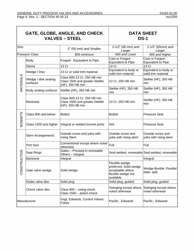
GENERAL DUTY PROCESS VALVES AND ACCESSORIES 24182.01.00 Page 6, Rev. 2 - SECTION 40 05 23 ms1259
GATE, GLOBE, ANGLE, AND CHECK
VALVES – STEEL
DATA SHEET
DS-1
Size 2” (50 mm) and Smaller
2-1/2” (65 mm) and Larger
2-1/2” (65mm) and Larger
Pressure Class 800 minimum 600 and Lower 900 and Higher
MA
TE
RIA
LS
Body Forged - Equivalent to Pipe Cast or Forged- Equivalent to Pipe
Cast or Forged- Equivalent to Pipe
Stems 13 Cr 13 Cr 13 Cr
Wedge / Disc 13 Cr or solid trim material Equivalent to body or solid trim material
Equivalent to body or solid trim material
Wedge / disk seating surfaces
Class 800-13 Cr, 250 HB min Class 1500 and greater-Stellite (HF), 350 HB min
13 Cr, 250 HB min Stellite (HF), 350 HB min
Body seating surfaces Stellite (HF), 350 HB min Stellite (HF), 350 HB min
Stellite (HF), 350 HB min
Backseat Class 800-13 Cr, 250 HB min Class 1500 and greater-Stellite (HF), 350 HB min
13 Cr, 250 HB min Stellite (HF), 350 HB min
BO
NN
ET
S
Class 800 and below Bolted Bolted Pressure Seal
Class 1500 and higher Integral or welded bonnet joints N/A Pressure Seal
CO
NS
TR
UC
TIO
N
Stem Arrangements Outside screw and yoke with rising Stem
Outside screw and yoke with rising stem
Outside screw and yoke with rising stem
Port Size Conventional except where noted otherwise
Full Full
Seat Rings Gates – Pressed-in renewable Others – Integral
Seal welded, renewable Seal welded, renewable
Backseat Integral Integral
Gate valve wedge Solid wedge
Flexible wedge preferred. Solid wedge acceptable where flexible wedge not available.
Wedge-flexible; Parallel slide- split
Globe valve disc Solid plug Solid plug, guided Solid plug, guided
Check valve disc Class 800 – swing check Class 1500 – piston check
Swinging except where noted otherwise
Swinging except where noted otherwise
Manufacturer Vogt, Edwards, Control Valves: Fisher.
Pacific, Edwards Pacific, Edwards

24182.01.00 GENERAL DUTY PROCESS VALVES AND ACCESSORIES ms1259 SECTION 40 05 23 - Page 7, Rev. 2
BALL VALVES – STEEL DATA SHEET
DS-2
Service
Steam service with design temp greater
than 300°F (149°C)
Oil and Natural Gas
Water, Steam, Gas, or Air service with design
temp less than 300°F
(149°C)
Pressure Class 600 and above 300 and below 300 and below
MA
TE
RIA
LS
Body Equivalent to pipe Equivalent to pipe Equivalent to pipe
Ball: Stainless steel Stainless steel
Class 1500 and below 410SS coated or A182-410 / Ram31
Class 2500 and above Inconel 718 or A182-410/Ram31
Stems Stainless steel Stainless steel
Class 1500 and below A276 Gr. 431 Nitrided or A638 Gr. 660/H.F.
Class 2500 and above 431SS or A638 Gr. 660/H.F.
Seats: Nylon with seat ring and emergency gasket
PTFE or RPTFE
Class 1500 and below 410SS coated or A182-F22 CL3/H.F.
Class 2500 and above Inconel 718 or A182-F22 CL3/H.F.
Seat Ring Equivalent to pipe Equivalent to pipe
Seals:
Body TFE PTFE or RPTFE
Stem TFE with emergency backup seal
PTFE or RPTFE
CO
NS
TR
UC
TIO
N
Valve Style Unibody 3-piece Design Pressure less than or equal to 150 psig- 2 piece unless noted otherwise; Above 150 psig- 3 piece
Design
Fire tested in accordance with API-607.
Bore Size Full Full Full
Valve end type Welded
2” and less- Threaded 2.5” and larger- Flanged
2” and less- Threaded 2.5” and larger- Flanged
Manufacturer Mogas, Valvtechnologies, or Conval
Neles-Jamesbury "Fire-Tite," Marpac, Valvtechnologies
Neles-Jamesbury Corp., Lunkenheimer, Apollo,

GENERAL DUTY PROCESS VALVES AND ACCESSORIES 24182.01.00 Page 8, Rev. 2 - SECTION 40 05 23 ms1259
BRONZE AND IRON VALVES DATA SHEET
DS-4
Gate, Globe, and Checks Ball
Size 2” (50 mm) and Less 2-1/2” (65 mm) and Larger
4" (100 mm) and Less
Pressure class 150 psig (1035 k Pa g)at
220°F (104°C) 125 psig at 220°F
(104°C)
125 psig (860 k Pa g)
MA
TE
RIA
LS
Body Bronze ASTM A126 Class B Cast Iron
Bronze
Ball n/a n/a Bronze
Gate valve wedge Bronze Cast iron with bronze face rings
n/a
Globe valve disc TFE Renewable Bronze n/a
Check valve disc Bronze Ductile Iron n/a
Stems Silicon Brass ASTM B16 Brass Bronze
Seats and Seals Steam service- TFE Water, oil, gas- Buna-N
Bronze, ASTM B61 RPTFE
Internals Bronze Renewable Bronze
CO
NS
TR
UC
TIO
N
Stem Inside screw with rising stem Outside screw and yoke with Rising Stem
Blowout proof
Packing Aramid fibers with graphite Aramid fibers with graphite
PTFE
Bore Size Full Full Full
Ball valve body n/a n/a 2 piece
Valve end type Threaded, unless noted otherwise
Flanged, unless noted otherwise
Pipe MaterialSteel
End TypeThreaded
Manufacturer Nibco, Watts, Crane Nibco, Watts, Crane Nibco, Watts, Apollo
END OF SECTION
1) M. R. Fritz 2) B. A. Pankow
24182.01.00 FABRICATED STACK ms1259 SECTION 44 11 39-13 - Page 1, Rev. 1
PART 1 GENERAL
1.01 SECTION INCLUDES
A. Stack.
B. Insulation.
C. Test ports.
D. Painting and finishes.
E. Testing.
F. Welding inspection.
1.02 INFORMATIONAL SUBMITTALS
A. Product Data: 1. Structural design criteria. 2. Installation instructions.
1.03 ACTION SUBMITTALS
A. Shop Drawings: 1. Manufacturer. 2. Model. 3. Dimensional outline. 4. Materials of construction. 5. Shipping weight. 6. Details of breeching connection. 7. Stack design shall be performed and sealed by a registered structural engineer licensed in State
of Illinois.
B. Quality assurance data: 1. Welders’ qualifications. 2. Computations:
a. Analysis of wind loadings. b. Dynamic analysis: Vortex shedding, critical wind velocity(ies), if applicable. c. Stress distribution. d. Reinforcement requirements at openings, platform, and base. e. Heat transfer calculations for stack metal temperature and flue gas temperature drop distribution. f. Analysis of seismic loads.
3. Loading Information: a. Total dead load. b. Design wind shear and moment at base. c. Design seismic shear and moment at base. d. Requirements for support steel framing deflection. e. Number, type, size, and location of anchor bolts, and connection detail at base.
4. Performance data. 5. Performance guarantees. 6. Test reports. 7. Certificates.
C. Design loads: Provide reactions, magnitude and directions, of all structures (stack, support frames, miscellaneous structures, etc). Provide individual load cases (dead load, live load, wind, etc) and load combination.

FABRICATED STACK 24182.01.00 Page 2, Rev. 1 - SECTION 44 11 39-13 ms1259
1.04 CLOSEOUT SUBMITTALS
A. Operation and maintenance data.
1.05 QUALITY ASSURANCE
A. Regulatory requirements: 1. Stack shall be UL-listed and tested. 2. Construct stack in accordance with latest applicable requirements of standard specifications and
codes of ANSI, ASME, ASTM, AISC, AWS, NFPA, and other such regular published and accepted standards except where modified or supplemented by these specifications; and in accordance with applicable requirements of federal OSHA Standards, and applicable local codes and standards.
1.06 DELIVERY, STORAGE, AND HANDLING
A. Clean prior to shipping.
B. Factory seal openings to prevent foreign material from entering during transit.
C. Clearly mark port locations on equipment.
D. Crate and cover equipment to facilitate handling and to withstand normal shipping and handling shocks and vibrations.
E. Unloading of stack from delivery vehicle will be performed by Buyer’s contractor.
PART 2 PRODUCT
2.01 MANUFACTURERS
A. Amerex Industries, Inc.
B. Commonwealth Dynamics, Inc.
C. Hamon Custodis-Cottrell, Inc.
D. International Chimney
E. Schebler.
F. Van Packer.
G. Warren Environment, Inc.
H. Or equal.
2.02 DESIGN REQUIREMENTS
A. Equipment: Boiler 4.
B. Design inner diameter for 30 to 80 fps maximum flue gas velocity with unit at full capacity.
C. Height of stack above boiler base: 115’-0” (35 m), existing roof at approximately 54’ (16 m) above boiler base.
D. Corrosion allowance: 1/8" (3 mm).

24182.01.00 FABRICATED STACK ms1259 SECTION 44 11 39-13 - Page 3, Rev. 1
E. Wind loads: In accordance with applicable provisions of 2009 IBC 30 psf on top 25’ (8 m) of stack, above roof.
F. Seismic loads: In accordance with applicable provisions of 2009 IBC.
G. Allowable stresses shall not be increased due to wind.
H. Maximum allowable stress in shell shall not exceed permissible stress with appropriate safety factor based on shell buckling criteria.
I. Stack deflection, not considering base rotation, due to static wind load and assuming 100% loss of corrosion allowance, shall not exceed 6" per 100’ (150 mm per 30 m). Assume lateral support only, no vertical support, can be provided at existing roof level.
J. Size anchor bolts for allowable stress of 15,000 psi based on gross area for ASTM A36. Size shall consider combination of stress from tension and shear assuming bolts or shear lugs only take horizontal shear forces at base.
2.03 STACK
A. Type: Single-wall, factory-built, sectional, maximum of 2 sections.
B. Fabricate in cylindrical sections sized suitable for shipping and space constraints of site.
C. Design: 1. Free-standing, self-supporting, vertical structure. 2. Shell shall resist stresses resulting from weight of stack, effect of wind, and shall resist corrosion
from weather. 3. Assume existing roof can be used to provide lateral support only. 4. Provide vertical loads required to be supported on Buyer’s structural steel.
D. Form shell of sheared plates to specified diameters; when stack diameters exceed available mill plate lengths or site access conditions, 2 or more plates may be used to form shell.
E. Shell construction: 1. Maximum deviation of base or support ring from centerline of stack: ±3/16" (5 mm). 2. Plumb to within maximum deviation of 1” per 100’ (25 mm per 30 m) of height. 3. Maximum out-of-roundness of any section (difference between minimum and maximum diameter):
Less than 2% of normal diameter. 4. Maximum misalignment of plates at any joint: 25% of nominal thickness of 1/8" (3 mm) whichever
is less. 5. Pair adjoining plate sections for full 100% development.
F. Include lifting lugs on each stack section.
G. Welded construction with girth and vertical seams of complete penetration butt welds to develop strength of plate; partial penetration welds not acceptable.
H. Flanges or flange type joints not acceptable, except those required for breeching connection.
I. Provide base anchorage system to transmit forces in shell to support steel through anchor bolts without inducing local stresses of appreciable magnitude in shell.
J. Provide stack inlet connection with angle flange for connection to expansion joint at economizer outlet.
2.04 INSULATION
A. Field insulation of stack below roof level: By others.

FABRICATED STACK 24182.01.00 Page 4, Rev. 1 - SECTION 44 11 39-13 ms1259
B. Include insulation support clips attached to stack wall.
2.05 ANCHOR BOLTS
A. Furnish stack support steel anchor bolts to be installed by others in structural steel. Provide necessary installation details.
2.06 TEST PORTS
A. Provide flue gas test ports welded to shell. Terminate with standard 150 lb raised face flange with face 4" (100 mm) outside of shell.
B. Use Type 316 stainless steel flanges and bolts with Monel nuts for test ports.
C. Provide two 4" (100 mm) diameter test ports located approximately 46'-0" (14 m) (to be verified after award of Contract) above boiler base at 90º from each other. Design for 300 lb (136 kg) horizontal load, 300 lb (136 kg) vertical load and 600 ft-lb (800 N-m) moment, applied at outer end of test port.
2.07 SAMPLE PORTS
A. Provide flue gas sample ports welded to shell. Terminate with standard 150 lb raised face flange with face 4” outside of shell.
B. Opacity monitor ports: Two 4” (100 mm) diameter ports, 180º from each other at 48’-0” (15 m) (to be verified after award of Contract) above boiler base. Design for 300 lb (136 kg) horizontal load, 300 lb (136 kg) vertical load and 600 ft-lb (800 N-m) moment, applied at outer end of test port.
C. Provide ports for installation of oxygen and NOx analyzers at suitable location. Coordinate port sizes as required for analyzers provided.
2.08 COATINGS
A. Perform after fabrication and complete before delivery to site.
B. Clean exterior surfaces and prepare for painting in accordance with SSPC-SP10 to 1.5-2 mil surface profile.
C. Cleaned surfaces shall be painted same day they are cleaned.
D. Primer: Dampney Protective Coatings Thurmalox 260 Series. 1. Apply 1 coat at 2.0 to 2.5 mils DFT. 2. Color: Gray.
E. Finish coat: Dampney Protective Coatings Thurmalox 260 Series. 1. Apply 1 coat at 2.0 to 2.5 mils DFT. 2. Color: Black.
F. Apply each coat at proper consistency and to thicknesses recommended by manufacturers. Materials shall be evenly spread and applied smoothly without runs or sags, by skilled workers. Do painting under conditions suitable to production of high quality work. Follow manufacturer's directions on container label.
G. Touch up primer and finish coat at job site as needed. Follow manufacturer’s recommendations
2.09 SOURCE QUALITY CONTROL
A. QA/QC program manuals shall be available for inspection.

24182.01.00 FABRICATED STACK ms1259 SECTION 44 11 39-13 - Page 5, Rev. 1
B. Permanently mark plates to identify quality and material.
C. Stack manufacturer shall have developed weld procedures, which, in conjunction with overall fabrication methods, will meet quality requirements of this specification.
D. Welding qualifications shall be available for inspection.
E. Weld inspection: 1. Finish welds shall be clean, showing good fusion, and 100% penetration with extensive visual
inspection. 2. Provide equipment and personnel to perform testing. Testing shall be performed not earlier than 5
days after giving notice to Buyer of date for testing. 3. Minimum testing: One radiographic test for each 150 linear feet (45 linear meters) of weld and
one ultrasonic test for each 20 linear feet (6 linear meters) of weld. Perform ultrasonic tests first. Location of tests shall be subject to review by Buyer.
4. Welds determined to be inadequate shall be removed and rewelded at Seller's expense. Perform 2 additional tests for each test indicating inadequate weld. Costs of additional tests shall be at Seller's expense.
F. Factory tests: 1. Notify Buyer 10 working days prior to conducting factory tests. Buyer, at its option, may witness
test. Buyer will notify Seller if it chooses to witness factory tests. 2. Perform nondestructive weld tests on equipment prior to shipment.
PART 3 EXECUTION
NOT USED END OF SECTION
1) M. R. Fritz 2) B. A. Pankow