INVITATION FOR BID FOR Philadelphia Police SWAT Unit ......Police SWAT Unit to satisfy a need for...
21
INVITATION FOR BID FOR Philadelphia Police SWAT Unit 8501 State Road Philadelphia, PA 19136 ISSUING OFFICE PENNSYLVANIA EMERGENCY MANAGEMENT AGENCY IFB NUMBER 6100031111 DATE OF ISSUANCE September 29, 2014
Transcript of INVITATION FOR BID FOR Philadelphia Police SWAT Unit ......Police SWAT Unit to satisfy a need for...
INVITATION FOR BID FOR
Philadelphia Police SWAT Unit
8501 State Road
Philadelphia, PA 19136
ISSUING OFFICE
PENNSYLVANIA EMERGENCY MANAGEMENT AGENCY
IFB NUMBER
6100031111
DATE OF ISSUANCE
September 29, 2014
Page 2
INVITATION FOR BID
FOR
TWO SPECIALIZED SWAT VEHICLES FOR EMERGENCY MANAGEMENT
OPERARTIONS
TABLE OF CONTENTS
SUMMARY SHEET 3
Part I—GENERAL INFORMATION 4
Part II— SPECIFICATIONS 7
Part III—REFERENCES, FINANCIAL INFORMATION, AND CONSTRUCTION 19
APPENDIX A, PROJECT BACKGROUND TEMPLATE
APPENDIX B, LOBBYING CERTIFICATION FORM
APPENDIX C, DISCLOSURE OF LOBBYING ACTIVITIES
APPENDIX D, STATE OF MANUFACTURING CHART
APPENDIX E, CONTRACT BOND
APPENDIX F, STATEMENT OF WORK – SPECIALIZED POLICE SWAT VEHICLES
APPENDIX G, VEHICLE REPORT (CHASSIS SPECS)
Page 3
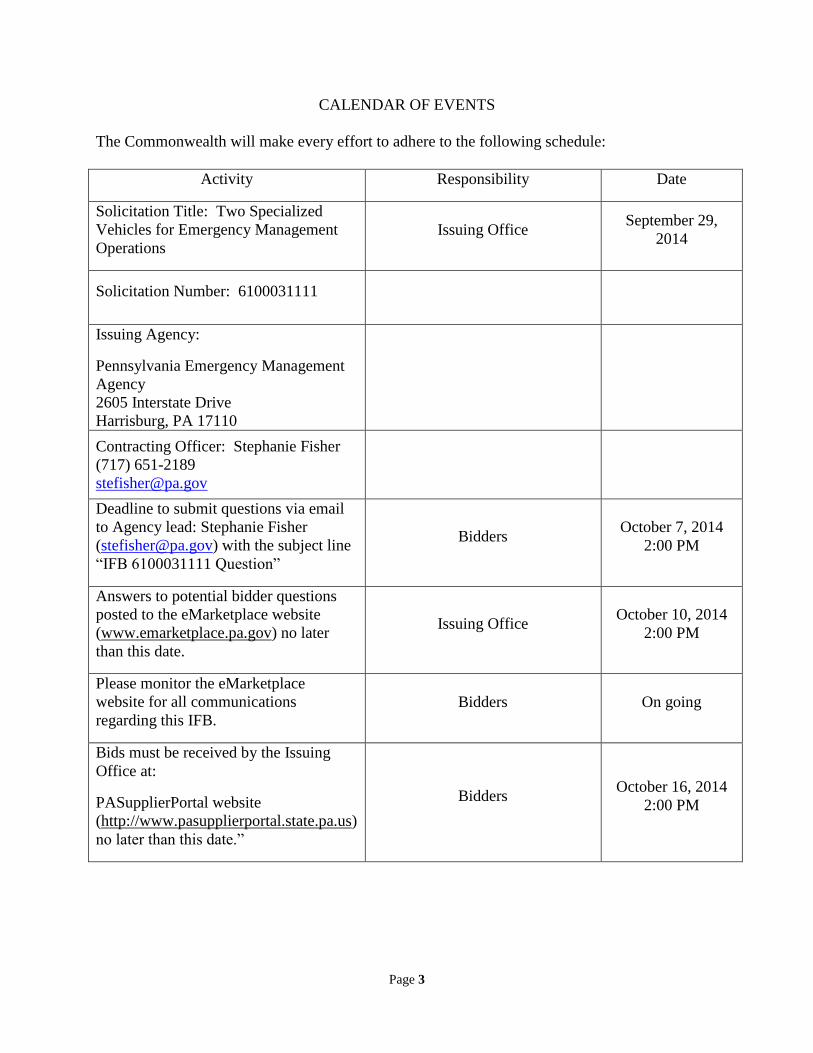
CALENDAR OF EVENTS
The Commonwealth will make every effort to adhere to the following schedule:
Activity Responsibility Date
Solicitation Title: Two Specialized
Vehicles for Emergency Management
Operations
Issuing Office September 29,
2014
Solicitation Number: 6100031111
Issuing Agency:
Pennsylvania Emergency Management
Agency
2605 Interstate Drive
Harrisburg, PA 17110
Contracting Officer: Stephanie Fisher
(717) 651-2189
Deadline to submit questions via email
to Agency lead: Stephanie Fisher
([email protected]) with the subject line
“IFB 6100031111 Question”
Bidders October 7, 2014
2:00 PM
Answers to potential bidder questions
posted to the eMarketplace website
(www.emarketplace.pa.gov) no later
than this date.
Issuing Office October 10, 2014
2:00 PM
Please monitor the eMarketplace
website for all communications
regarding this IFB.
Bidders On going
Bids must be received by the Issuing
Office at:
PASupplierPortal website
(http://www.pasupplierportal.state.pa.us)
no later than this date.”
Bidders October 16, 2014
2:00 PM

Page 4
PART I
GENERAL INFORMATION
Purpose
This Invitation for Bid (IFB) provides to those interested in submitting bids for the
subject procurement (Bidders) sufficient information to enable them to prepare and
submit bids for the Pennsylvania Emergency Management Agency for the Philadelphia
Police SWAT Unit to satisfy a need for TWO Specialized SWAT Vehicles.
Issuing Office
The Pennsylvania Emergency Management Agency (Issuing Office) has issued this IFB
on behalf of the Philadelphia Police SWAT Unit. The sole point of contact in the
Commonwealth for this IFB is Stephanie Fisher [email protected], 2605 Interstate Drive,
Harrisburg, PA 17110, the Issuing Officer for this IFB. Please refer all inquiries to the
Issuing Officer.
Problem Statement
The purpose of this IFB is to purchase two Specialized SWAT Vehicles for Emergency
Management Operations. The special-purpose vehicles are for the transport of response
equipment and personnel to incident sites which may have limited or restricted access as
a result of an emergency or disaster. The vehicles will carry breaching search and rescue
tools, night vision equipment, ladders, ballistic shields and SCBA equipment to rapidly
deploy to a terrorist attack or Weapon of Mass Destruction.
Questions and Answers
If a Bidder has any questions regarding this IFB, the Bidder must submit the questions by
email (with the subject line "“IFB 6100031111 Question”) to the email address specified
in the Calendar of Events. If the Bidder has questions, they must be submitted via email
no later than the date and time specified in the Calendar of Events. The Bidder shall not
attempt to contact the Issuing Officer by any other means. The Issuing Officer will post
the answers to the e-Marketplace website. A Bidder who submits a question after the
deadline date for receipt of questions indicated on the Calendar of Events assumes the
risk that its bid will not be responsive or competitive because the Commonwealth is not
able to respond before the bid receipt date or in sufficient time for the Bidder to prepare a
responsive or competitive bid. When submitted after the deadline date for receipt of
questions indicated on the Calendar of Events, the Issuing Officer may respond to
questions of an administrative nature by directing the questioning Bidder to specific
provisions in the IFB. To the extent that the Issuing Office decides to respond to a non-
administrative question after the deadline date for receipt of questions indicated on the
Calendar of Events, the answer will be provided to all Bidders through an addendum.
All questions and responses as posted on the e-Marketplace website are considered as an
addendum to, and part of, this IFB. Each Bidder shall be responsible to monitor the
eMarketplace website for new or revised IFB information. The Issuing Office shall not
be bound by any verbal information nor shall it be bound by any written information that
Page 5
is not either contained within the IFB or formally issued as an addendum by the Issuing
Office. The Issuing Office does not consider questions to be a protest of the
specifications or of the solicitation.
Addenda to IFB
If the Issuing Office deems it necessary to revise any part of this IFB before the due date,
the Issuing Office will post an addendum to the e-Marketplace website. Answers to the
questions asked during the questions and answer period will also be posted to the
eMarketplace website as an addendum to the IFB.
Electronic Version of IFB
This IFB is being made available by electronic means. The Bidder acknowledges and
accepts full responsibility to insure that no changes are made to the IFB. In the event of a
conflict between a version of the IFB in the Bidder's possession and the Issuing Office's
version of the IFB, the Issuing Office's version shall govern.
Response Date
A bidder’s electronic bid must be submitted via the PASupplierPortal website on or
before the due date specified in the Calendar of Events. Any bid submitted to the Issuing
Office in hardcopy format will be rejected.
Incurring Costs
The Issuing Office is not liable for any costs the Bidder incurs in preparation and
submission of its bid, in participating in the IFB process or in anticipation of award of a
contract.
Restriction of Contact
From the issue date of this IFB until the Issuing Office selects a bid for award, the Issuing
Officer is the sole point of contact concerning this IFB. Any violation of this condition
may be cause for the Issuing Office to reject the offending bidders bid. If the Issuing
Office later discovers that the bidder has engaged in any violations of this condition, the
Issuing Office may reject the offending bidders bid or rescind its contract award. Bidders
must agree not to distribute any part of their bids beyond the Issuing Office. Any bidder
who shares information contained in its bid with other Commonwealth personnel and/or
competing bidder personnel may be disqualified.
Prime Contractor Responsibilities
The Contractor will be required to assume responsibility for all services offered in its bid
whether it produces them itself or by subcontract. The Issuing Office and Project
Manager will consider the Contractor to be the sole point of contact with regard to
contractual and purchase order matters.
Rejection Of Bid
The Issuing Office reserves the right, in its sole and complete discretion, to reject any bid
received in response to this IFB.

Page 6
Term
The contract resulting from this IFB will commence on the effective date, as defined in
the Terms and Conditions and will extend for the duration of the project. No work may
begin or be reimbursed prior to issuance of a fully executed purchase order. Final
payment will not be made until all work has been successfully completed.
Terms and Conditions
The requirements and terms and conditions shall govern the contract issued as a result of
this IFB.
Bidding Reference Material
Bidding Process Reference Guide
Supplier Response to a Solicitation - Brochure
Attaching Follow-On Documents to your Bid
Bidding Frequently Asked Questions (FAQ's)

Page 7
PART II
SPECIFICATIONS & REQUIREMENTS
Specifics
The Pennsylvania Emergency Management Agency is requesting, on behalf of the
Philadelphia Police SWAT Unit, two specialized police SWAT vehicles for emergency
management operations.
Certifications Manufacturer shall be ISO9001 certified. Certification requirement removed per
Addendum 1 dated 10/07/2014
Vendor Requirements and Standards
All equipment shall be new and not used, refurbished, and/or overhauled. No
substitutions will be accepted. The vendor shall ensure that all work, installations, and
necessary documentation conform to the requirements of the National Electrical Code
and the National Fire Protection Association publication NFPA-110.
Completed unit, exclusive of chassis and other purchased major components, to be
constructed and assembled at a single manufacturing facility, to include all body
fabrication, painting, electrical, pump installation and plumbing (when applicable), and
assembly/installation of skid unit (when applicable). No outsourcing to subcontractors
shall be permitted.
Insurance Customer's chassis to be insured by chassis-owner against fire, theft, vandalism, storm
damage, etc. while at Awarded Vendor facilities.
Warranty The following warranty will apply to new All-Aluminum Skidder Body/Equipment built
by Awarded Vendor.
Structural Warranty - (10) ten years/ (120) months from date of delivery to original
owner for 100% of expense to perform required replacement/repairs to correct defects in
design, construction, materials and/or workmanship against cracking and/or perforation
caused by corrosion including:
Body Framing/Crossmembers
Compartment/Body Doors
Exterior/Interior Panels
Treadplate Panels/Trim
Compartment Boxes
Corrosion Warranty - (5) five years (60) months from date of delivery to original
owner for 100% of expense to perform required replacement/repairs to correct
defects in exterior/interior body finish against corrosion damaged caused by
reaction between dissimilar metals and/or defects in undercoating, caulking and/or
painting process. Paint Warranty – (5) five years (60) months from date of
Page 8
delivery to original owner for 100% of expense to perform repainting as provided
by the PPG Commercial Refinish Product Warranty. Paint warranty to include:
Peeling or delaminating of the topcoat and/or other layers of paint
Cracking or checking due to failure of the product
Excessive loss of gloss caused by cracking, checking, and hazing.
Paint warranty does not include:
Paint deterioration cause by blistering or other film degradation due to rust or
corrosion originating from the substrate
Hazing, chalking, or loss of gloss caused by improper care, abrasive polishes,
cleaning agents, heavy-duty pressure washing, or aggressive mechanical wash
systems
Paint deterioration caused by abuse, scratches, chips, gloss reduction, accidents,
acid rain, chemical fallout or acts of nature
Repairs done over previously refinished area unless stripped to bare metal or
appropriate substrate
Failure on finishes performed by non-PPG Commercial Certified Technicians or
by non-PPG Commercial Certified Centers
Failures on finishes due to inadequate film builds
Failure due to improper cleaning or surface preparation or failure to follow the
product use instructions.
Electrical/Trim Warranty - (2) years/ (24) months from date of delivery to original
owner for 100% expense to perform required replacement/repair to correct defects
in design, installation, and/or workmanship including:
12 Volt Wiring
Generator/Pump Installation(s)
110/220 Volt Wiring
Lighting Installation(s)
Upholstery/Trim
Hardware/Plating/Fasteners
Tread Plate Trim Panels
Lettering/Striping
Windows (Excluding Glazing)
Warranty Policy/ Procedure(s):
Awarded Vendor warrants the above listed body and equipment in accordance with the
above time limits, beginning with delivery of completed body/equipment to customer.
Notification of Warranty Claim must be submitted within the above warranty period(s).
All Warranties voided by accident repair(s)/body modification(s)/transfer to new chassis
by a party other than Awarded Vendor unless approved in writing by Awarded Vendor.
All Warranties voided upon transfer of ownership to another party from original owners.
Upon notification, Awarded Vendor will perform required repair/replacement work under
the following procedures. Awarded Vendor reserves the right to stipulate which
procedure warranty work will be performed by.
At customer’s location by Awarded Vendor service personnel.
At customer’s location by qualified outside contractor upon receipt by Awarded
Vendor of quotation/approval for said work.
Page 9
At Awarded Vendor’s garage, in which case the unit will be returned to Awarded
Vendor at owner’s expense.
Auxiliary Equipment Items - auxiliary equipment items not manufactured by
Awarded Vendor to carry manufacturer replacement/repair warranty and labor
policy including but not limited to:
Pumps
Air Conditioners
Generators
Winches
Warning Devices
Chassis/Equipment
Performance Specifications
The following specifications are submitted in order to describe the design, work,
materials and equipment to be utilized in the fabrication of two specialized, all-aluminum
police SWAT units.
Substitutions are allowable as long as they meet or exceed the specifications of the listed
Brands/Part Numbers.
CHASSIS:
Year: 2015 Make: Ford Model: F-350 SuperCab 4X4
Additional Chassis Equipment Items:
Front Tow Hooks – Supplied with chassis cab.
Rear Receiver Hitch w/ 7-pin connector – One (1) Reese class V 2” rear receiver,
#45014 with 14,000 lbs. gross towing weight rating installed to rear frame rails. One (1)
7-pin electrical connector installed at hitch location and connected to chassis trailer tow
circuitry.
Rear Cab Storage Cabinet – Rear cab jump seat/risers removed. Cabinet constructed of
.125” smooth aluminum installed to utilize space in back of cab. Cabinet to be approx.
42.00” high x 18.00” wide lower)/13.00” wide (upper), with front of cabinet tapered to
allow comfortable driving position for front seat backs. Cabinet to be full-through across
back of cab. Two (2) full-width shelves installed inside of cabinet at 16.00” height and
30.00” height. Shelves to have 1-1/2” double break-overs at each end to help keep items
on shelves. Cabinet securely bolted through cab floor.
Equipment Box – One (1) aluminum box constructed of .125” smooth aluminum
installed between front cab seats. Box to be 12” L x 12” W x 14-1/2” H. Box to have lid
hinged towards cab dash with pull knob. Exterior of box finished in black Zolatone.
Page 10
Space left in front of equipment box for installation of laptop computer pedestal/mount,
to be customer supplied/installed at a later date.
BODY CONSTRUCTION/MATERIALS:
Subsills - .500" x 3.00" full-length flat aluminum body subsills
Crossmembers - Four (4) 2.00” x 3.00” x full body width x .125” wall tubular aluminum
body crossmembers full-welded to above subsills, one (1) set behind front body panel,
one (1) located at rear of front compartment boxes, one (1) located at front of rear
compartment boxes, and one (1) set behind rear body panel. Three (3) 2.00" x 3.00" x
38.00” x .125" wall tubular aluminum body crossmembers full-welded to above subsills,
one (1) set mid way between front and rear full width crossmembers, one (1) set in center
of wheelhousing area, and one (1) set mid way between the two rear full width
crossmembers. Four (4) 2.00” x 2.00” x .125” wall tubular spacers welded to top of
crossmembers, 19” in length, between body crossmembers and upper/wheelhousing
compartments to provide tire/chain clearance.
Front Body Panel - .188" aluminum 38.00" wide x 49.00" high front body panel
constructed with 1 ½” side return flanges. Panel bolted to 1 ½” return flange of side
compartments boxes with Silkaflex adhesive caulking applied between flanges prior to
installation.
Compartments - Six (6) aluminum modular-free standing full-welded compartment
boxes installed - two (2) each 36.00" wide x 63.00" high x 21.00" deep lower/thru-body
above frame, forward body area, two (2) each 44.00" wide x 43.00" high x thru-body, and
two (2) 30.00” wide x 59.00” high x thru-body aft of rear axle. Note – compartment
dimensions do not reflect actual door openings. Compartment boxes to be constructed of
.125” smooth aluminum with panels forming front and rear body panels to be constructed
of .188” aluminum. Compartments stripwelded to forward body panel, adjacent
compartment and body crossmembers. Compartments to have full-welded seams and 1-
5/8" x 1-1/2" door opening flange(s). Lower compartment floor flanges turned downward
to create "sweep-out" type compartment floors.
Special Transverse Compartments – Compartments L-1/R-1 and L-3/R-3 to have
aboveframe, full-through compartment boxes. Compartments L-2/R-2 to also be full-
through compartments.
Rear Body Wheelhousing/Skirt Panels - .125" aluminum tread/brightplate lower
wheelhousing/rear body skirt panels installed with opening for rear chassis wheels and
chassis fuel fill. Skirt panels extended to approx. 4" above center-line of rear chassis
wheels. Panels extended from lower/forward compartment to rear body skirt panel and
have 2" lower panel reinforcement lip.
Rear Body Panel - .125" aluminum tread/brightplate 38.00" wide rear-facing body panel
installed in center-line of lower/rear body skirt area from rear step level to 4" above rear
body crossmember.
Page 11
Interior Electrical Cover Panels - removable panels constructed of .125” aluminum
installed at front of wall of compartment L-1/R-1 and rear wall of compartments L-3/R-3
to protect wiring to rear body panel warning and DOT lighting.
Top Body Deck Risers – four (4) 1.75” x 1.00” x full length x .125” wall tubular
aluminum risers installed on top of exterior compartment boxes to create space under top
body decks for installation of wiring.
Top Body Decks - .125" aluminum tread/brightplate top body decks installed full-length
x fullwidth of upper deck areas created by above compartment box ceilings. Decks to
have 3.00" front, rear and side-facing 90-degree lips with corners full welded.
Top Body Header Extensions w/ Painted Side Panels – Compartment header heights
increased to appox. 3” for installation of warning lights. Exterior panel constructed of
.080” smooth aluminum, painted job color.
(SPECIAL) – Additional 1.75” x 1.00” x .125” wall tubular aluminum risers installed
above center of compartment boxes to provide additional body support and attachment
points for roof panels.
Rubrail Caps - .125" aluminum tread/brightplate 2.00" wide rubrail caps extended from
front body corners to wheelhousing panel - one each side under forward compartment
door opening(s).
COMPARTMENT DOORS:
Compartment door openings equipped with ROM Robbins roll-up type shutter doors
installed per ROM installation specifications with following features:
Self-contained door ajar switch
Drip rail with V-seal, full length of body and door width on rear.
Brushed Anodized finish
Power Locking Door System
REAR BUMPER:
(SPECIAL) – 3” x 1” x 12ga. steel C-channel outriggers extended off of rear of chassis
frame rails, welded to 3” x 1” x 12ga. steel cross tube spanning width of body. All steel
framing painted black prior to installation of bumper. Cross tube covered in .125”
aluminum bright/treadplate bumper, full body width x 6” high x 3” deep. Underside of
bumper undercoated prior to installation. Outside edges of bumper set of 45-degree angle.
BODY MOUNTING:
Sub-Sills - Two (2) .750" x 3.00" composite rot-resistant frame sills installed - full length
between chassis frame rails and body subsills.
Fuel Fill – OEM fuel fill kit installed with Cast Products hinged spring-loaded access
door
installed on body left side wheelhousing panel.
U-bolts - Six (6) .625" body mounting U-bolts installed - three (3) each side
Page 12
Undercoating - Body skirting areas undercoated with Dolphin Dolchem #7955 Hydro-
Armor undercoating material prior to body mounting. All tread plate areas coated with
neoprene based Silaprene on body-side surfaces prior to installation.
Mudflaps – One (1) pr. AWARDED VENDOR anti-spray mudflaps installed behind rear
wheels.
Exhaust – Ford factory exhaust tip extended (if necessary) to outer edge of lower body
skirting.
BODY MODIFICATIONS/COMPARTMENT ITEMS
Adjustable Compartment Shelf Tracks – All body compartments to have #TB9034
adjustable compartment tracks installed, four (4) tracks each compartment side wall, for
mounting of following dual-direction slide-out decks. Adjustable tracks installed with
fasteners. Track lengths sized appropriately to allow adjustment of dual-direction trays
while maintaining clearance for items on roll-out trays located on compartment floors.
Dual-Direction Heavy-Duty Slide-Out Decks – Six (6) Innovative Industries
SlideMaster Model SM2-D, dual-direction, heavy-duty slide-out decks installed, two (2)
decks each compartment thru-body area. Decks to extend 70% out either side of body.
Lower decks installed on compartment floors with upper decks installed on adjustable
shelf track material. Decks to have 1,000 lbs. distributed load capacity. Each deck to have
tray constructed of .125” smooth aluminum with D/A matte finish. Trays to have 1-1/2”
sides installed. Tray in bottom of L-2/R-2 to have 6” high sides. Trays to be full length
and width (allowable) of compartment thru-area. Trays to have 1” reflective red and
white conspicuity tape installed on face and sides of trays.
Innovative 300 lbs. Slide-Out Trays – Three (3) Innovative Industries SlideMaster
ModelSM2-LP, 70% extension, 300 lbs. capacity, steel construction, slide-out trays
installed, with lock-in/lock-out mechanisms. One (1) tray installed on floor of each
compartment L-3, R-1 and R-3. Trays to be full width and depth of compartments as
allowable by roll-up door tracks. Trays constructed with .125” smooth aluminum with
D/A matte finish and have 2” lips on all four sides. Back of trays to have offset for body
spring shackle housings. Trays to have 1” reflective red and white conspicuity tape
installed on face and sides of tray.
Special – Tray in bottom of R-1 to have 8” high sides to act as a tool box for loose
equipment.
Special Equipment Locker Enclosure – 6” deep bottom tray in compartment L-2/R-2 to
have locking enclosure built around tray. Tray to have 6” x full length x full width blue
Styrofoam block supplied for customer to make cut-out for special equipment. Enclosure
to provide 13” of clearance from bottom of tray to underside of aluminum cross-bars.
Aluminum angle cross-bars installed across top of tray, covered in expanded aluminum
material. Each side of enclosure to have flip-down, treadplate door installed. Doors to

Page 13
have full-width, stainless steel, piano-type hinges installed with locking paddle-type
handles installed. Doors to securely latch to aluminum angle cross bar installed on either
end of enclosure.
Dri-Dek Compartment Matting – Dri-Dek brand heavy-duty compartment rubber deck
tiles installed on all compartment dual-direction trays and lower pull-out trays, except for
lower special equipment storage tray in L-2/R-2. Dri-Dek also installed on lower
compartment floor L-1.
Black Rubber Fenders - Full arch type black rubber fenders installed at rear wheel
openings with stainless steel washers and bolts.
Side Bolt-On Rubrails – Body side bolt-on C-channel rubrails constructed of 3/16”
aluminum with D/A matte finish applied. Rubrails to be 1-1/2” H x 1-1/2” deep, installed
with ¼” vinyl washers between back of rubrail and side of body to allow debris to pass
behind rubrail when washing vehicles. Face of rubrails to have white Scotchlite material
installed. Ends of rubrails to have 45-degree bevels installed.
PAINTING:
Disassembly – All bolt on body exterior hardware, trim panels and moldings removed
prior to painting preparation, to include compartment doors.
Preparation – All exterior body surfaces thoroughly sanded with dual action air disc
type sander using #320 grit sandpaper prior to prime painting.
Prime Painting – All specified area prime-painted with PPG #F3950 non-sanding
primer/sealer. Prior to finish painting, two (2) additional coats of color paint shall be
applied and then the entire painted surface to be finish sanded with #400 grit sand paper.
Finish Painting – All exterior body surfaces finish painted with two (2) wet-on-wet coats
of PPG Delfleet “Evolution” base coat and two (2) wet-on-wet coats #F3925 clear.
Finish paint to be applied using individual one (1) quart siphon feed HVLP air spray guns
set at 50-60 PSI regulated pressure. Finish painting to be performed in twelve thousand
(12,000) CFM down draft paint booth having 12,000 CFM Trane air replacement/heat
unit and two (2) eight thousand (8,000) CFM under floor exhaust fans to maintain
atmospheric pressure during painting operation, while exchanging booth air one (1) time
per minute.
Specified Painting-
Body Exterior – Ford Oxford White, to match cab
Note - Body understructure to be undercoated as specified above
Reassembly – All removed body hardware, trim panels and moldings to include
compartment doors to be reinstalled using specified hardware fasteners. All moldings and
hardware to have supplied gaskets installed during final re-assembly. Body hardware not
supplied with gaskets and exterior compartment door hinge mounting surface to have

Page 14
isolation tape installed between fixture and body panel. All exterior “D” type door
handles and grab rail stanchions to have molded neoprene rubber gaskets installed
between fixture and body panel/surface.
12VDC ELECTRICAL:
Wiring - All body wiring to be 14 ga. color coded stranded type wiring installed in
protective split looms with solderless connectors. All LED warning/DOT light wiring to
be minimum 18 ga. color coded stranded type, or as otherwise specified by lighting
manufacturer. Body electrical equipment to include:
Step/License Light – One (1) Kaper II chrome framed surface mounted step/license light
mounted on lower rear body splash pan and connected to chassis tail light circuit.
Stop/Tail, Turn, Back-Up Lights – Two (2) Code 3 #65PKG triple-stack LED DOT
light clusters installed, to include one (1) #65STR back-up light, one (1) #65STA amber
turn signal light, and one (1) #65RV back-up light. Lights installed in #65STK3 triple-
stack, cast aluminum housings. One light cluster installed on each lower rear body panel,
interfaced with chassis circuitry.
Body Marker/ICC – All body Marker/ICC lights to be Kaper II LED type with chrome
trim rings.
DOT Flares - One (1) set triangular DOT reflective flares installed.
Back-up Alarm – One (1) Ecco #550 connected to chassis back-up light system. Back
up alarm to have minimum 87 dbA rating. OPTIONAL 12VDC ELECTRICAL
Emergency Service Package – Package to include one (1) cab center console
constructed of .125” smooth aluminum with Zolatone #20-71 Onyx Black exterior finish.
Console lid constructed of ½” MHDB black plastic board with textured surface, routed
with quarter-round edge around perimeter of lid. Lid fastened to console with counter
sunk hardware. Interior floor of console to be 5/8” exterior grade plywood for mounting
of remote siren heads, circuit breakers, 12-volt power posts, and other electrical
components located inside of console. Console to include storage area at back for two (2)
2” binders. Equipment to be installed in console to include optional equipment such as
sirens, radios, traffic advisor control head, gauges, switches etc. Relays, breakers, power
supplies, etc. installed in 12VDC electrical panel in vented aluminum load center box
with removable lid. Console to include clam-shell type Carlin rocker switches with back-
lite lables for all specified 12VDC loads.
Special – Delete cab center console – above box installed only. One (1) ventilated
enclosure to house all 12-volt relays, circuit breakers, and power supplies constructed and
installed in bottom of compartment L-1 (unless otherwise specified). Each component
identified by number/color and function and listed within control panel. Main service
cable shall be 1/0 stranded insulated cable, rated to 210 amps continuous service and
protected by a 200 amp automatic reset circuit breaker. Enclosure to provide for ease of
Page 15
transfer of body/equipment to new chassis. Enclosure constructed of Formica covered ¼”
plywood with .125” smooth aluminum top and sides with .125” aluminum removable lid.
Aluminum to have “D/A” matte finish to match inside of compartment box. Two (2) 4”
round metal louvers installed in lid for proper ventilation of enclosure. All 12-volt loads
to be energized by chassis ignition switch. All circuits in excess of 10 amps shall be
operated by means of a 30 amp 12 VDC automotive type relay. Relays shall be ground
controlled by lighted rocker switches in cab radio/switch console and connected by
twenty (20) gauge stranded cable. One main automatic reset circuit breaker and
individual automotive-type automatic reset circuit breakers installed in enclosure for each
circuit.
Special – All switching to be done through following Code 3 Siren Head/Switch
Controller unit.
*Note - center console requires removal of 40/20/40 center bench seat section.
All electrical to meet current NFPA 1901 2009 edition standards.
LED Compartment Lighting – All exterior compartments supplied with On Scene
Solutions Access strip lighting. One (1) strip installed on each right side interior
compartment side wall at door opening. Light strips to stop approx. 2” from compartment
floor and 2” from door roll at top of compartment box. Access light strips to produce 400
lumens of light per every 18” of length, encased in durable 5/8” Lexan tube, fully sealed
waterproof design, have a lifespan of approximately 50,000 hours, and carry a 5-year
manufacturer’s replacement warranty. Lights installed with manufacturer’s mounting
brackets, set on a 45-degree angle to project more light into the compartment box. All
lights interfaced with individual ROM magnetic door ajar switches.
Back-Up Camera - One (1) Safety Vision #SL-CLCD-70B, 7” color back-up camera
system installed. Rear color camera installed in center on top of rear of body. Color
screen and bracket installed on cab dash in plain sight of driver.
Interior LED Dome Light – One (1) Whelen 60C0EJCS 6” white, 6 diode LED,
surfacemount interior light with self-contained light switch, mounted on cab headliner
between two front seats.
Streamlight Installation – Installation provided in bottom of compartment L-1 for one
(1) customer-supplied Streamlight hand light with 12-volt charging base. Power supply
for charging base ran off of chassis battery to provide continuous charging of hand light.
12-Volt Electrical Performance Test Documentation - Low voltage performance test
conducted per guidelines of NFPA 1901 2009 13.14 with test report supplied in the
owner’s manual.
ELECTRICAL 120/240VAC All body wiring, for optional 110/220VAC equipment,
installed prior to installation of exterior body panels. All wiring to be minimum 12-3
SOO type cable installed with required under body junction boxes, box connections and
wiring clips. All wiring routed to master circuit breaker panel installed in compartment,
with required individual circuit breaker for each equipment and receptacle circuit. Circuit
breaker box cover labeled as to individual breaker function.
Page 16
Specified 120/240VAC – None.
WARNING LIGHTS & SIRENS
LED Warning Lights - Body – Six (6) Code 3 #45BZRB split red/blue Super-LED
lights installed, one (1) each lower body wheelhousing panel, and two (2) each upper side
body panel. Lights to have clear lenses, installed with chrome flange rings. Two (2) Code
3 #65BZRB split red/blue Super-LED lights installed, one (1) each upper rear body
panel. Lights to have clear lenses, installed with chrome flange ring. Lights controlled by
switch(es) on cab center console/switch panel.
LED Warning Lights – Intersection/Grille – Four (4) Code 3 #MR6FM-R/B Super-
LED lights installed, two (2) red and two (2) blue, on chassis grille, arranged in an “X”
pattern. Two (2) Code 3 #MR6FM-RB split red/blue Super-LED lights installed, one
each front fender. All lights to have clear lenses with surface mount grommets. Lights
controlled by switch on cab center console/switch panel.
Wig-Wag Headlights Flasher – One (1) Code 3 #700 Wig-Wag headlight flasher
installed and connected to chassis headlights. Headlight flasher handles up to two (2) 8-
amp loads. Headlight flasher controlled by switch for grille/intersection lights.
Whelen RX2700 Bar Light – One (1) Code 3 RX2700 series LED bar light installed on
forward cab roof. Bar light controlled by switch installed on cab center console. Bar light
configured as follows:
Model 2747AC, 47” in length
Two (2) corner red Prizm II LED’s (driver’s side)
Two (2) corner blue Prizm II LED’s (passenger side)
Two (2) front-facing red Prizm II LED’s (driver’s side)
Two (2) front-facing blue Prizm II LED’s (passenger side)
Two (2) front-facing center LED take-down lights
Two (2) LED Alley lights, one (1) each end of bar light
One (1) LIT3KIT-TT 2-pr. Torus lower level LED lights, (2) blue, (2) red
Permanent mount kit.
Siren Head/Controller and Speakers – One (1) Code 3 Remote Lighted Siren #3998R,
200-watt, full-feature electronic siren with integrated switch panel, installed to underside
of cab dash. Siren head to include 3-position slide switch with six (6) additional push-
button switches with back-lit labels. Siren wired to two (2) Code 3 #C3100U, 100-watt
siren speakers with universal brackets, mounted behind chassis front bumper.
AUXILIARY EQUIPMENT
LETTERING/STRIPING:
All lettering/striping to be supplied/installed by customer after delivery.
Page 17
ADDITIONAL INFORMATION
INSPECTIONS:
Customers inspect progress on their new apparatus twice during the build process. The
first inspection should be done upon mounting of the body onto the chassis. At this point,
the customer should select placement of items such as electrical outlets, special shelves,
junction boxes, the battery conditioner, switch layout, placement of hand lights, etc. The
second inspection should be done prior to delivery of the completed apparatus. At this
inspection, the customer should inspect the craftsmanship of unit, verify that the
specifications/design have been met, and can also make any final requests for minor
changes and additions. All travel expenses related to inspections shall be incurred by the
customer. Customers are welcome to make as many inspections as they wish (within
reason). All inspections are to be scheduled in advance with Awarded Vendor sales
personnel. Inspection teams are requested to not exceed six (6) company personnel.
Customers who fail to perform any inspections of their unit, while in production, forfeit
the right to request any changes (free of charge) to the placement of items that were to be
placed by the customer and not specifically spelled out in the specification, after the
completed unit is delivered.
CHANGES & ADDITIONS:
All Changes & Additions to contract, including additional charges or credits, shall be
submitted to customer for approval. All submissions, accepted or rejected, shall be
returned to Awarded Vendor. In the case of an accepted Change & Addition, the work
shall not be implemented until such time as the necessary documents have been returned
to Awarded Vendor and the conditions (terms), if any, of the order have been satisfied.
RESEARCH AND DEVELOPMENT
Due to the constant updating and improvement of designs and equipment by chassis
manufacturers, and subsequent changes in model numbers and designs of chassis-
specific, aftermarket equipment items, Awarded Vendor reserves the right to substitute
model numbers of equipment items for the specific model year of the chassis being
supplied without notice to the customer. Due to constant updating and improvements of
designs by our suppliers, Awarded Vendor reserves the right to supply equipment items
equal or superior to the model number of the equipment items contained within these
specifications, without notice to the customer.
MANUFACTURING HISTORY:
Completed unit, exclusive of chassis, to be built by a company who has been in the
continuous manufacture of motorized emergency equipment for a minimum of ten (10)
years.

Page 18
Submittals
Within 10 days after receipt of purchase order, the bidder shall submit 2 complete
submittal sets (1 set to Philadelphia Police SWAT Unit and 1 set to PEMA) that include:
- Specification sheet.
- Dimensional elevation and layout drawings of the modular/trailers.
- Awarded supplier’s written warranty.
Operations and Service Documentation to be submitted with delivery of vehicles- As-
built vehicle specifications, equipment manuals, instructions, service manuals, warranty
registration cards, and parts lists shall be installed in binder form and installed in
completed vehicles.
Production and Delivery Timeline
Awarded vendor shall provide a detailed timeline that includes dates for production,
training, delivery and acceptance. Project must be complete by Tuesday May 31, 2015.
Page 19
PART III
REFERENCES AND FINANCIAL INFORMATION
Firm Qualification Requirements
The Bidder must have been actively engaged in the sale of, manufacture of and/or
installation of equipment/services similar to the item(s) required in this solicitation for a
period of at least ten years.
The Bidder shall demonstrate its engagement in three projects requiring services
that are similar in size and scope to those requested in this solicitation, and that have been
in continuous operation for at least one year. Using Appendix B, Project Background
Template, and the Bidder shall submit the requested information for each of the three
projects as part of its bid.
Performance Bond
The awarded Bidder shall provide PEMA with a Performance Bond executed by a
surety company authorized to do business in the Commonwealth of Pennsylvania and
made payable to PEMA in the amount of one hundred percent (100%) of the contract
value within ten (10) days of notice of award of contract. PEMA may collect on the
bond if the awarded contractor fails to perform the services as required by this IFB or if
the awarded contractor fails to honor the price guarantees and/or satisfy the performance
guarantees in the contract resulting from this IFB.
Failure to furnish the required performance bond within the required ten (10) day
time frame shall be considered a failure to perform a contractual obligation which may
result in termination of the contract and award to another bidder. In the event of
termination and re-award for failure to provide a performance bond, the Contractor shall
be responsible for any increase in cost to the Commonwealth. Where the Contractor does
not comply with the requirements of the contract, the amount of the performance bond
shall be paid to the Commonwealth as liquidated damages for the contractor‘s failure to
comply, or the Commonwealth may, at its sole option, sue the contractor or its surety for
the damages it has suffered for any breach of contract.
Payment Schedule
Payment will be made per the attached terms and conditions and upon acceptance
of the generator and training.
Installation/Construction
If the contractor is required to install equipment or perform construction to
provide the services required by this contract, certain statutory provisions maybe required
based upon the total cost of the equipment, the type of equipment, and type of installation
or construction. Those provisions include, but may not be limited to, the following:
A. DOMESTIC WORKFORCE UTILIZATION CERTIFICATION: To the extent
that any services, such as design and consulting services could be performed outside
of the geographical boundaries of the United States, the Contractor will be required
to certify that those services will be performed exclusively within the geographical
boundaries of the United States or specify the percentage of the direct labor that will

Page 20
be performed outside of the United States. The certification form will be included
with the written solicitation for quotes and must be completed by the Contractor.
The using agency will use the certification in making a best value selection.
Reference Appendix H – Domestic Workforce Utilization Certification.
B. STEEL PRODUCTS PROCUREMENT ACT “A”: In the performance of any
contract awarded pursuant to this invitation to bid, the contractor, subcontractors,
material men, or suppliers shall use only Steel Products, rolled, formed, shaped,
drawn, extruded, forged, cast, fabricated or otherwise similarly processed, or
processed by a combination of two or more of such operations, from steel made in
the United States by the open hearth, basic oxygen, electric furnace, Bessemer or
other steel making process. Steel Products include not only Cast Iron Products but
also Machinery and Equipment listed in United States Department of Commerce
Standard Industrial Classification 25 (furniture and fixture), 35 (machinery, except
electrical) and 37 (transportation equipment) and made of, fabricated from, or
containing steel components. If a product contains both foreign and United States
steel, such products shall be determined to be a United States Steel product only if at
least 75% of the cost of the articles, materials and supplies have been mined,
produced or manufactured, as the case may be, in the United States. Transportation
equipment shall be determined to be a United States steel product only if it complies
with Section 165 of Public Law 97-424 (96 Stat. 2136).
When unidentified steel products are supplied under a contract, before any payment
will be made, the contractor must provide documentation including, but not limited
to, invoices, bills of lading and mill certification that the steel was melted and
manufactured in the United States. If a steel product is identifiable from its face, the
contractor must submit certification which satisfies the using agency that the
contractor has fully complied with this provision. The Department shall not provide
for or make any payment to any person who has not complied with the Act. Any
such payments made to any person by the Department which should not have been
made as a result of the Act shall be recoverable directly from the contractor,
subcontractor, manufacturer or supplier who did not comply with the Act.
In addition to the withholding of payments, any person who willfully violates any of
the provisions of the Act shall be prohibited from submitting any bids to any public
agency for a period of five (5) years from the date of the determination that a
violation has occurred. In the event the person who violates the provisions of the
Act is a subcontractor, manufacturer or supplier, such person shall be prohibited
from performing any work or supplying any materials to a public agency for a
period of five (5) years from the date of the determination that a violation has
occurred.
The contractor shall include the provisions of the Steel Products Procurement Act in
any subcontract and supply contract, so that the provisions of the Act shall be
binding upon each subcontractor and supplier. Reference Appendix I – State of
Manufacturing Chart.

Page 21
C. PROHIBITION AGAINST THE USE OF CERTAIN STEEL AND
ALUMINUM PRODUCTS: In accordance with the Trade Practices Act of July
23, 1968 P.L. 686 (71 P.S. Section 773.101 et seq.), the contractor cannot and shall
not use or permit to be used in the work any aluminum or steel products made in a
foreign country which is listed below as a foreign country which discriminates
against aluminum or steel products manufactured in Pennsylvania. The countries of
Brazil, South Korea, Spain and Argentina have been found to discriminate against
certain products manufactured in Pennsylvania. Therefore, the purchase or use of
those countries’ products, as listed below, is not permitted.
(i) BRAZIL: Welded carbon steel pipes and tubes; carbon steel wire rods; tool steel;
certain steel products, including hot-rolled stainless steel bar; stainless steel wire
rod and cold-formed stainless steel bar; pre-stressed concrete steel wire strand;
hot-rolled carbon steel plate in coil; hot-rolled carbon steel sheet and cold-rolled
carbon steel sheet.
(i) SPAIN: Certain stainless steel products, including stainless steel wire rod, hot-
rolled stainless steel bars and cold-formed stainless steel bars; pre-stressed
concrete steel wire strands certain steel products, including hot-rolled steel plate,
cold-rolled carbon steel plate, carbon steel structural shapes, galvanized carbon
steel sheet, hot-rolled carbon steel bars and cold-formed carbon steel bars.
(ii) SOUTH KOREA: Welded carbon steel pipes and tubes; hot-rolled carbon steel
plate; hot-rolled carbon steel sheet and galvanized steel sheet.
(iii)ARGENTINA: Carbon steel wire rod and cold-rolled carbon steel sheet.
Penalties for violations of this paragraph may be found in the Trade Practices Act,
which penalties include becoming ineligible for public works contracts for a
period of three years.
NOTE: THIS PROVISION IN NO WAY RELIEVES THE CONTRACTOR OF
ITS RESPONSIBILITY TO COMPLY WITH THOSE PROVISIONS OF THIS
INVITATION TO BID WHICH PROHIBIT THE USE OF FOREIGN-MADE
STEEL AND CAST IRON PRODUCTS.