
Investment casting of Ti–46Al–8Nb–1B alloy using...
12
Investment casting of Ti–46Al–8Nb–1B alloy using moulds with CaO-stabilized zirconia face coat at various mould pre-heat temperatures Yuan, Chen; Cheng, Xu; Holt, Grant; Shevchenko, Dmytro; Withey, Paul DOI: 10.1016/j.ceramint.2014.11.109 License: Creative Commons: Attribution (CC BY) Document Version Publisher's PDF, also known as Version of record Citation for published version (Harvard): Yuan, C, Cheng, X, Holt, G, Shevchenko, D & Withey, P 2015, 'Investment casting of Ti–46Al–8Nb–1B alloy using moulds with CaO-stabilized zirconia face coat at various mould pre-heat temperatures' Ceramics International, vol. 41, no. 3, pp. 4129-4139. DOI: 10.1016/j.ceramint.2014.11.109 Link to publication on Research at Birmingham portal Publisher Rights Statement: Eligibility for repository : checked 16/06/2015 General rights Unless a licence is specified above, all rights (including copyright and moral rights) in this document are retained by the authors and/or the copyright holders. The express permission of the copyright holder must be obtained for any use of this material other than for purposes permitted by law. • Users may freely distribute the URL that is used to identify this publication. • Users may download and/or print one copy of the publication from the University of Birmingham research portal for the purpose of private study or non-commercial research. • User may use extracts from the document in line with the concept of ‘fair dealing’ under the Copyright, Designs and Patents Act 1988 (?) • Users may not further distribute the material nor use it for the purposes of commercial gain. Where a licence is displayed above, please note the terms and conditions of the licence govern your use of this document. When citing, please reference the published version. Take down policy While the University of Birmingham exercises care and attention in making items available there are rare occasions when an item has been uploaded in error or has been deemed to be commercially or otherwise sensitive. If you believe that this is the case for this document, please contact [email protected] providing details and we will remove access to the work immediately and investigate. Download date: 28. Aug. 2018
Transcript of Investment casting of Ti–46Al–8Nb–1B alloy using...

Investment casting of Ti–46Al–8Nb–1B alloy usingmoulds with CaO-stabilized zirconia face coat atvarious mould pre-heat temperaturesYuan, Chen; Cheng, Xu; Holt, Grant; Shevchenko, Dmytro; Withey, Paul
DOI:10.1016/j.ceramint.2014.11.109
License:Creative Commons: Attribution (CC BY)
Document VersionPublisher's PDF, also known as Version of record
Citation for published version (Harvard):Yuan, C, Cheng, X, Holt, G, Shevchenko, D & Withey, P 2015, 'Investment casting of Ti–46Al–8Nb–1B alloyusing moulds with CaO-stabilized zirconia face coat at various mould pre-heat temperatures' CeramicsInternational, vol. 41, no. 3, pp. 4129-4139. DOI: 10.1016/j.ceramint.2014.11.109
Link to publication on Research at Birmingham portal
Publisher Rights Statement:Eligibility for repository : checked 16/06/2015
General rightsUnless a licence is specified above, all rights (including copyright and moral rights) in this document are retained by the authors and/or thecopyright holders. The express permission of the copyright holder must be obtained for any use of this material other than for purposespermitted by law.
•Users may freely distribute the URL that is used to identify this publication.•Users may download and/or print one copy of the publication from the University of Birmingham research portal for the purpose of privatestudy or non-commercial research.•User may use extracts from the document in line with the concept of ‘fair dealing’ under the Copyright, Designs and Patents Act 1988 (?)•Users may not further distribute the material nor use it for the purposes of commercial gain.
Where a licence is displayed above, please note the terms and conditions of the licence govern your use of this document.
When citing, please reference the published version.
Take down policyWhile the University of Birmingham exercises care and attention in making items available there are rare occasions when an item has beenuploaded in error or has been deemed to be commercially or otherwise sensitive.
If you believe that this is the case for this document, please contact [email protected] providing details and we will remove access tothe work immediately and investigate.
Download date: 28. Aug. 2018

CERAMICSINTERNATIONAL
Available online at www.sciencedirect.com
http://dx.doi.org/0272-8842/Crow
nCorrespondinE-mail addre
(2015) 4129–4139
Ceramics International 41 www.elsevier.com/locate/ceramintInvestment casting of Ti–46Al–8Nb–1B alloy using mouldswith CaO-stabilized zirconia face coat at various mould
pre-heat temperatures
C. Yuana,n, X. Chenga, G.S. Holta, D. Shevchenkoa, P.A. Witheya,b
aSchool of Metallurgy and Materials, The University of Birmingham, Birmingham B15 2TT, England United KingdombRolls-Royce plc, PO Box 31, Derby DE24 8BJ, England, United Kingdom
Received 18 September 2014; received in revised form 14 November 2014; accepted 20 November 2014Available online 2 December 2014
Abstract
Casting of titanium based alloys presents considerable problems including the extensive interactions that occur between the metal andrefractory. An investigation was undertaken to develop a zirconia facecoat suitable to replace current zircon/silica facecoat used in investmentcasting titanium aluminide alloys. The stability of the zirconia slurry was assessed using pH, viscosity and plate weight, and the mould propertiessuch as friability, strength and permeability were measured. The interaction between the zirconia face coat and a Ti–46Al–8Nb–1B alloy wasstudied by centrifugal investment casting at three mould pre-heating temperatures. Computer simulation of metal cooling profiles during castingwas also carried out to assist the analysis. In this work, a stable zirconia slurry was developed, and the moulds produced using a zirconia facecoathave comparable mechanical properties and better permeability than those made of the traditional zircon/silica facecoat. The friability of thezirconia facecoat was much improved in comparison to that made of yttria face coat. During casting, metal non-fill defects were presented at alow preheat mould temperature of 500 1C. The interaction products found between the metal and mould included a combined (Ti, Zr)5(Si, Al)3and ZrAl2 phases, a re-precipitated ZrO2 phase, and a Al2O3 film at the interface. The interaction between mould and metal also caused a highhardness at the interface due to oxygen penetration, which varied with samples using different mould pre-heat temperatures. The suggestion hasbeen made that the mould pre-heat temperature should be less than 1200 1C.Crown Copyright & 2014 Published by Elsevier Ltd and Techna Group S.r.l. All rights reserved.
Keywords: D. ZrO2; Facecoat; Investment casting; Titanium aluminide
1. Introduction
The first attempts to cast titanium alloys were made in 1950 [1]and these alloys are now widely used in the aerospace, energy andchemical industries. Investment casting is a possible manufacturingroute to produce near net shape titanium components. The cost ofproducing titanium components by other fabrication methods isrelatively high, as a result of intrinsic raw materials costs and themetal removal cost associated with producing the required shape.Thus, recent attention has focussed on the development of castingalloys containing a large percentage of other alloying elementsto reduce reactivity, alloy costs and density. Gamma titanium
10.1016/j.ceramint.2014.11.109n Copyright & 2014 Published by Elsevier Ltd and Techna Group
g author. Tel.: þ44 1214147839; fax: þ44 1214147890.ss: [email protected] (C. Yuan).
aluminides are a family of low density, high performance alloyswith the potential to replace current Ni-base superalloys used in theproduction of aero-engine components [2]. Titanium aluminidesare difficult to process mainly due to [3]:
�
S.
high melting temperature and poor fluidity,
� strong chemical activity of the molten metal, � low density combined with high viscosity in themolten state.
Extensive interactions occur between the molten alloy and therefractory moulds, leading to a reaction zone with alpha-case onthe surface of the casting and oxide inclusions in the bulk alloy.Alpha-case refers to an oxygen-rich interaction layer on the surfaceof the casting [4], which is detrimental to the mechanical properties
r.l. All rights reserved.
C. Yuan et al. / Ceramics International 41 (2015) 4129–41394130
of the finished component, and has to be removed by chemicalmilling or shot blasting.
Traditionally almost all investment moulds use water-basedcolloidal silica as a binding system [5]. Research has shown [5,6]that the majority of metal–mould interaction is due to reduction ofsilica, present as binder and filler phases, by both titanium andaluminium in the molten state. In order to further eliminate theinteraction between the mould and metal, mould materials withhigh chemical inertness have been used as the face coat materialduring the investment casting process. Yttria has been investigatedas a mould material with improved chemical inertness during TiAlcasting [7], but the limiting factors on the use of this oxide are thatyttria sols are exceptionally unstable and prone to gellation andyttria filler is relatively expensive. By considering productioncosts, face coat materials such as ZrO2 [8,9] are considered as facecoat materials for TiAl alloy casting in industry.
Due to the poor fluidity of gamma TiAl around its meltingtemperature, the mould for investment casting TiAl is normallypre-heated to help the alloys flow to avoid mis-run and cold lapsin the cast parts [10,11]. However, the excessive preheatingaccelerates metal–mould reaction of titanium castings [12] andmay increase the propensity for surface-connected porosity.Therefore, a balance must be found in order to achieve propertiesaccording to design requirements. Kim et al. [13] claim that thespiral fluidity of TiAl alloys is directly related to the mouldpreheating temperature in the range of 400–800 1C. Jovanovićet al. [14] showed that defects such as misrun and macroporeswere found in the casting when the preheat temperature of mouldswas below 500 1C. Applying higher preheat temperature between750 and 800 1C successfully eliminated many of these defects.
In this study, an investigation was undertaken to develop azirconia facecoat suitable to replace current zircon/silica facecoatin investment casting of titanium aluminide alloys. The stability ofthe facecoat slurry is assessed by viscosity, pH and plate weight.The properties of the moulds were evaluated by friability, strengthand permeability measurement. The interaction between thezirconia face coat and a Ti–46Al–8Nb–1B alloy was studied ata range of preheat temperatures between 500 1C and 1200 1Cusing full-scale casting. The effect of preheat temperature onreaction was studied with the assistance of simulation of metalcooling profiles during casting at various conditions. The sub-sequent interaction between mould and alloy was investigated.
2. Experimental procedures
2.1. Slurry development and characterisation
Slurries were mixed from ammonium colloidal zirconia sol(Ti-coat) with a CaO stabilised filler (ABSCO, �325 mesh).
Table 1Details of shell systems chosen for reaction analysis.
Shell system Binder Filler refractory
Standard primary Remet LP colloidal silica Minco fused silica �200Zirconia primary (ZrO2) Remet colloidal zirconia Calcia stabilised zirconiaStandard secondary Remet LP colloidal silica Minco fused silica �200
The ratio of CaO doped ZrO2 filler to sol was 3.5 kg/l sol. Thestability of the resultant slurry was characterised by measure-ments of viscosity, pH and plate weight. The viscosity wasdetermined from the time required for a definite volume ofslurry to flow through the orifice in the bottom of a metal flowcup, in this case 70 ml of slurry passing through a B5 cup with4.76 mm orifice diameter. To determine the plate weight ofslurry, a metal plate with a size of 45 mm � 45 mm wasdipped into slurry for 1 min and drained for 150 s. The weightchange of the slurry during the initial 150 s was recorded atintervals of 15 s and the reading at 120 s taken as plate weightof slurry.
2.2. Ceramic shell production and characterisation
2.2.1. Mould productionThe detailed constituents of the zirconia primary coat and
comparable standard zircon/silica primary coat and secondarycoats are listed in Table 1. The moulds were made by firstinvesting the wax pattern into the primary slurry. A chosen stuccowas then applied by the rainfall sanding method. The coat wasdried at a temperature of 21 1C, 50% relative humidity and 0.2 m/s air speed for 24 h. Six backup coats were then applied. Analumino-silicate stucco (IMERYS, Molochite 30/80 mesh) wasapplied as the secondary stucoo in layers 2 and 3. A coarseralumino-silicate stucco (IMERYS, Molochite 16/30 mesh) wasapplied as secondary stucoo in layers 4–7. Each secondary coatwas dried at a temperature of 21 1C, 50% relative humidity and3 m/s air speed for 90 min. Finally a seal coat of secondary slurrywas applied and dried at a temperature of 21 1C, 50% relativehumidity and 3 m/s air speed for 24 h. The wax inside the ceramicmould was then removed by steam autoclaving at 8 bar pressurefor 4 min, followed by a controlled de-pressurisation cycle at1 bar min�1 using a Quicklock BoilerclaveTM (Leeds and Brad-ford Boiler Company Ltd., UK).
2.2.2. FriabilityThe friability test was specifically designed as a quality control
procedure to determine the tendency of the solid to be broken intosmall pieces by friction force. Measuring friability was mainly toassess the degree of sintering and the possibility of incorporatinginclusions into the alloys, which could cause a typical contamina-tion occurring in casting. Test samples for friability measurementare produced by shelling wax bars of 20 mm diameter. Thesamples were weighed, and the internal diameter and the totallength of the tubes were also measured. The test brush was pushedthrough the tube fully, and pulled back through. The samples werereweighed, and the brushed weight subtracted from the initialweight to give change in weight, G. The calculation of the
Stucco refractory
mesh ECC Molochite �200 mesh Alumino-silicate 30/80 mesh�325 mesh Calcia stabilised zirconia 50/100 meshmesh ECC Molochite �200 mesh Alumino-silicate 30/80 and 16/30 mesh

C. Yuan et al. / Ceramics International 41 (2015) 4129–4139 4131
friability (F) is given by
F ¼ G
πDLð1Þ
where D is internal diameter, and L is sample length.
2.2.3. Room temperature flat bar strength measurementStrength measurements were carried out in accordance with
BS 1902. Test pieces, approximately 20 mm� 80 mm werecut using a diamond wheel. To simulate casting conditions,bars were heated at 20 1C min�1 to the required maximumtemperature, 1000 1C in this case, held for 60 min and thenfurnace cooled to room temperature before testing. Sampleswere loaded in three-point bending test geometry (primary coatupwards) on an Instron 8500 tensile testing machine. The spanlength, L, was 50 mm. A load application rate of 1 mm min�1
was used. The failure strength, σMax was calculated as
σMax ¼3PMaxL
2WH2 ð2Þ
where PMax is the fracture load, and W and H are the width andthickness of sample fracture area respectively.
2.2.4. Permeability measurementsFor the measurement of permeability, a test piece former was
prepared, consisting of a mullite ceramic tube (6 mm internaldiameter and 10 mm outer diameter and 250 mm in length) and ahollow plastic ball (20 mm radius). A hole was cut into the ball andthe mullite tube inserted between 5 mm and 20 mm in the ball. Asmall fillet of wax was used to bond the tube to the ball and act asa sealant. The test pieces were then dipped to produce shellsamples. After drying, the samples were heated at 2 1C/min to700 1C and held for 6 min to burn out the plastic ball. After this,samples were heated at a rate of 20 1C min�1 to 1200 1C, held for60 min and then furnace cooled to room temperature. Testing wascarried out in accordance with BS 1902: Section 10.2:1994, at atest temperature of 1200 1C and with a slight adjustment of theequation for the dynamic viscosity of air. The pressure differenceand the flow were recorded at 5 and 10 min dwell times. Thepermeability of the shell, m (in m2), was calculated as
μ¼ ηVcl
aPð3Þ
with
Vc ¼V1T
T1ð4Þ
where
η is the dynamic viscosity of air at the temperature ofthe test (in N s/m2)
Vc is the volumetric flowrate of air corrected for expan-sion at elevated temperatures (in m3).
V1 is the volumetric flowrate of air at room temperatures(in m3).
l is the thickness of the shell mould (in m)a is the inner surface of the hollow shell mould (in m)P is the pressure difference across the test piece (in N/m2)
T is the elevated temperature (in Kelvin)T1 is the room temperature (in Kelvin)
2.3. Casting by an Induction Skull Melting (ISM) method
In order to carry out casting and interaction studies, full-scalemoulds were produced with zirconia face-coat to assess theinteraction during the casting process. The gravity-filled mouldscontained 200 mm long bars of 15 mm diameter attached to aconical pouring basin and a wheel-shaped running system. Afterdewaxing, the moulds were fired at 1000 1C for 1 h, cooled toroom temperature and inspected. Moulds were then placed inside agraphite mould heater inside a vacuum chamber containing anInduction Skull Melting (ISM) crucible. The chamber wasevacuated to a vacuum of better than 5� 10�2 mbar and themould preheated to one of three different temperatures 500 1C,1000 1C and 1200 1C and soaked for at least 1 h. The vacuumchamber was backfilled with argon to a partial pressure of200 mbar. A charge of a Ti–46%Al–8%Nb–1%B (at%) alloywas melted in the ISM crucible using a maximum power of350 kW and poured into the hot mould. The mould heater wasturned off and the mould allowed to cool in situ until a temperatureof 300 1C was reached. The vacuum chamber was opened toremove the mould which was then cooled to room temperature.Most of the mould material was removed mechanically and thecasting lightly shot blasted. Slices from bottom of the cast barswere cut and polished for further analysis. The microhardnessprofile at the metal–mould interface was obtained using a MitutoyoMVK-H1 hardness testing machine in order to characterise alphacase penetration; and SEM micrographs with EDX data were takenon a Jeol 7000/Jeol 6060 in order to characterise the metal–mouldinterface via elemental penetration into the melt.
2.4. Computer simulation of metal cooling profiles
The mould filling and alloy solidification were simulatedusing the software package ProCAST 10.0. The simulationprocedure consisted of the following three steps:
�
Mesh generation. � Model boundary condition and materials properties setup. � Post processing.The meshes of the mould and casting were generated withVisual-Mesh 8.5 software. The maximum tetra element size of thecasting rods was 0.5 mm; also two boundary layers with amaximum size of 0.1 mm were generated for better simulationof the heat loss to the mould. The mould mesh had a maximumelement size of 5 mm. Properties of the TiAl alloy measured byHarding et al. and Cagran et al. [15,16] were used for thesimulations. The mould properties were selected from theProCAST database. The list of the model initial conditions andboundary setup can be seen in Table 2. Post processing on theresults was also done with Visual-Mesh 8.5.

0
0.5
1
1.5
2
2.5
3
0 40 80 120 160
Plat
e W
eigh
t (g)
Plate Weight
C. Yuan et al. / Ceramics International 41 (2015) 4129–41394132
3. Results
3.1. Slurry stability study
The pH, viscosity and plate weight variation against mixingtime were recorded and are shown in Fig. 1. The viscosity ofthe slurry increased slightly over time, accompanying thedecrease in pH also observed, as shown in Fig. 1a. The changeof plate weight showed a similar trend to the change inviscosity, as shown in Fig. 1b. The slurry plate weight changeover 150 s is also illustrated in Fig. 2. Initially the slurrydropped off very quickly from the plate but reached a plateauafter draining for 70 s.
Table 2Model initial conditions and boundaries setup.
Initial mould temperature [1C] 500, 1000, 1200Alloy inlet temperature [kg/s] 1620 1CPouring rate 2.5Alloy mould heat transfer coefficient [W/m2 K] 2000Maximum mould filling [%] 98Maximum time step for filling [s] 0.01
9
9.5
10
10.5
11
11.5
0
4
8
12
16
20
0 5 10 15
Vis
cosi
ty B
5 70
ml (
s)
Mixing time (day)
Viscosity
pH
0
4
8
12
16
20
0
0.6
1.2
1.8
2.4
3
0 5 10 15
Plat
e w
eigh
t aft
er 1
20s (
g)
Mixing time (day)
Plate Weight
Viscosity
Fig. 1. The properties of zirconia slurry against mixing time: (a) pH andviscosity and (b) plate weight and viscosity.
Drain time(s)
Fig. 2. The draining curve of zirconia slurry over initial 150 s.
3.2. Measurements of the shell properties
The shell thickness, flat bar fracture strength, and perme-ability results obtained for the shell systems are shown inTable 3. In terms of green and fired strength, the properties ofthe zirconia shell system were all comparable to that of thestandard zircon/silica facecoat shell used for casting steel. Thepermeability of the zirconia mould is higher in comparison tothe standard system. The friability data is illustrated in Fig. 3.For the mould made of zirconia face coat, as sinteringtemperature increases, friability decreased slightly in a non-linear fashion from 1000 1C up to 1400 1C. This was comparedwith the friability of the yttria face coat in earlier work [17].
3.3. Metal/mould reaction during casting
3.3.1. Mis-run during castingTo help the alloys flow and to avoid mis-run and cold laps in
the cast parts, moulds are pre-heated to three differenttemperatures: 500 1C, 1000 1C and 1200 1C in this work.When the mould was only pre-heated to 500 1C, the mouldwas poorly filled by molten metal in the top 80 mm of the bars,as shown in Fig. 4. By increasing the temperature to 1000 1C,the mould was totally filled with only some vein defects foundon the surface of metal castings. No filling defects wereobserved when mould was pre-heated to 1200 1C.
3.3.2. Metal surface examination by XRDAfter casting and mould removal, the composition of the
metal surface was analysed using XRD, and the results areshown in Fig. 5. It can be seen that very strong ZrO2 peakswere detected on the metal piece surface in the form of bothmonoclinic and cubic phase. This is consistent with thefacecoat composition. However, SiO2 peaks were found atthe metal surface when cast into moulds pre-heated to 1000 1Cand 1200 1C, and the intensities of the peaks increased withincreasing mould pre-heating temperature.
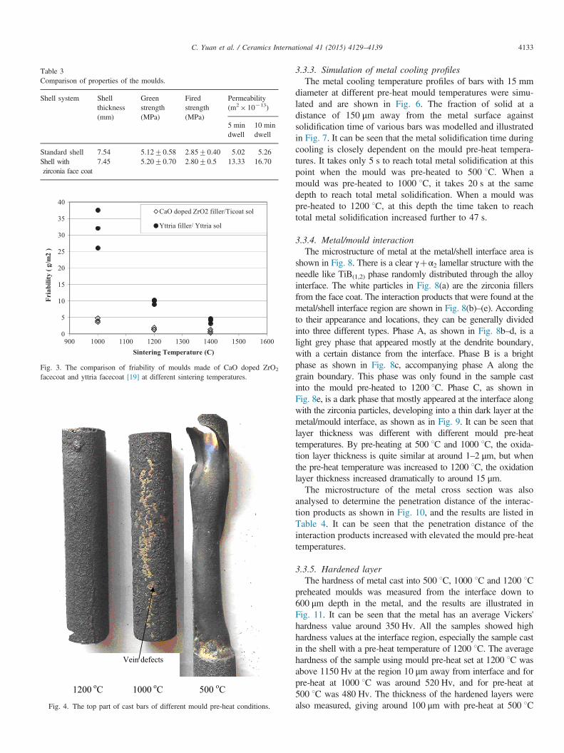
Table 3Comparison of properties of the moulds.
Shell system Shellthickness(mm)
Greenstrength(MPa)
Firedstrength(MPa)
Permeability(m2� 10�13)
5 mindwell
10 mindwell
Standard shell 7.54 5.1270.58 2.8570.40 5.02 5.26Shell withzirconia face coat
7.45 5.2070.70 2.8070.5 13.33 16.70
0
5
10
15
20
25
30
35
40
900 1000 1100 1200 1300 1400 1500 1600
Fria
bilit
y ( g
/m2
)
Sintering Temperature (C)
CaO doped ZrO2 filler/Ticoat sol
Yttria filler/ Yttria sol
Fig. 3. The comparison of friability of moulds made of CaO doped ZrO2
facecoat and yttria facecoat [19] at different sintering temperatures.
1200 oC 1000 oC 500 oC
Vein defects
Fig. 4. The top part of cast bars of different mould pre-heat conditions.
C. Yuan et al. / Ceramics International 41 (2015) 4129–4139 4133
3.3.3. Simulation of metal cooling profilesThe metal cooling temperature profiles of bars with 15 mm
diameter at different pre-heat mould temperatures were simu-lated and are shown in Fig. 6. The fraction of solid at adistance of 150 μm away from the metal surface againstsolidification time of various bars was modelled and illustratedin Fig. 7. It can be seen that the metal solidification time duringcooling is closely dependent on the mould pre-heat tempera-tures. It takes only 5 s to reach total metal solidification at thispoint when the mould was pre-heated to 500 1C. When amould was pre-heated to 1000 1C, it takes 20 s at the samedepth to reach total metal solidification. When a mould waspre-heated to 1200 1C, at this depth the time taken to reachtotal metal solidification increased further to 47 s.
3.3.4. Metal/mould interactionThe microstructure of metal at the metal/shell interface area is
shown in Fig. 8. There is a clear γþα2 lamellar structure with theneedle like TiB(1,2) phase randomly distributed through the alloyinterface. The white particles in Fig. 8(a) are the zirconia fillersfrom the face coat. The interaction products that were found at themetal/shell interface region are shown in Fig. 8(b)–(e). Accordingto their appearance and locations, they can be generally dividedinto three different types. Phase A, as shown in Fig. 8b–d, is alight grey phase that appeared mostly at the dendrite boundary,with a certain distance from the interface. Phase B is a brightphase as shown in Fig. 8c, accompanying phase A along thegrain boundary. This phase was only found in the sample castinto the mould pre-heated to 1200 1C. Phase C, as shown inFig. 8e, is a dark phase that mostly appeared at the interface alongwith the zirconia particles, developing into a thin dark layer at themetal/mould interface, as shown as in Fig. 9. It can be seen thatlayer thickness was different with different mould pre-heattemperatures. By pre-heating at 500 1C and 1000 1C, the oxida-tion layer thickness is quite similar at around 1–2 μm, but whenthe pre-heat temperature was increased to 1200 1C, the oxidationlayer thickness increased dramatically to around 15 μm.The microstructure of the metal cross section was also
analysed to determine the penetration distance of the interac-tion products as shown in Fig. 10, and the results are listed inTable 4. It can be seen that the penetration distance of theinteraction products increased with elevated the mould pre-heattemperatures.
3.3.5. Hardened layerThe hardness of metal cast into 500 1C, 1000 1C and 1200 1C
preheated moulds was measured from the interface down to600 μm depth in the metal, and the results are illustrated inFig. 11. It can be seen that the metal has an average Vickers'hardness value around 350 Hv. All the samples showed highhardness values at the interface region, especially the sample castin the shell with a pre-heat temperature of 1200 1C. The averagehardness of the sample using mould pre-heat set at 1200 1C wasabove 1150 Hv at the region 10 μm away from interface and forpre-heat at 1000 1C was around 520 Hv, and for pre-heat at500 1C was 480 Hv. The thickness of the hardened layers werealso measured, giving around 100 μm with pre-heat at 500 1C

Fig. 5. The XRD test results of the cast metal surface at different mould pre-heat temperatures.
Fig. 6. The simulation of solidification time profile of cylindrical bars of 15 mm diameter during cooling at various preheat temperatures: (a) 500 1C, (b) 1000 1C,and (c) 1200 1C.
Fig. 7. The fraction of solid against solidification time of 15 mm bars at150 mm from the surface during cooling at different solidification times.
C. Yuan et al. / Ceramics International 41 (2015) 4129–41394134
and 1000 1C temperatures, and around 150 μm at 1200 1C pre-heat temperature.
4. Discussions
4.1. Slurry properties
The increased viscosity, accompanying by the decrease inpH, over time could be related to the evaporation of ammonia
and water in the zirconia binder over the mixing time. Thoseeffects can be eliminated by regularly adjusting pH andviscosity with ammonia solution and water, which is a commonpractice in industry. The slurry is fairly stable over the 15-dayperiod and no gellation effect took place during this period oftime. The slurry plate weight change over 150 s shown in Fig. 2also demonstrates an ideal draining curve for slurry as itprovides uniform slurry coating over the wax pattern duringthe slurry draining period.
4.2. Mould properties
Results shown in Table 3 indicated that, in terms of green andfired strength, the properties of the zirconia shell system were allcomparable to that of the standard zircon/silica facecoat shellused for casting steel, so that the mould with the ZrO2 face coatcould withstand the de-waxing and casting processes.The higher permeability of the zirconia mould in comparison
to that of the standard system could be related to microcracksproduced due to some degree of zirconia phase transformationwhich has been previously reported [18]. As the strength of themould is mainly determined by secondary coats, the decrease inthe strength due to microcrack in the primary coat was notobserved in this study. Although it is thought that permeabilitythrough the shell is less important in vacuum casting, it has beenshown that reduced permeability is one of the fundamen-tal factors causing incomplete filling of metal castings [19].The reduction in gas flow leads to the trapping of residual gases

ZrO2 particles
Shell
Phase A
Phase B
Phase C
Phase A
Fig. 8. The microstructure of the TiAl alloy cast into zirconia face-coat mould at 1200 1C pre-heat temperature, showing: (a) the backscatter image of the metal/shell interface region; (b)–(d) location of and morphologies of the phases A and B; (e) location of and morphologies of the dark phase C.
C. Yuan et al. / Ceramics International 41 (2015) 4129–4139 4135
and an increased back-pressure within the cavities of the mould.In turn, this reduces metal flow, especially towards the top of amould where the metallostatic head is lower. This is especiallyimportant for gamma TiAl castings as the alloy density is lowand the fluidity is decreased due to the low superheats achieved
for these reactive alloys. Therefore the higher permeability in azirconia mould would be a favourable effect for castinggamma TiAl.The friability data illustrated in Fig. 3 shows that much
better surface sintering properties were found in the zirconia
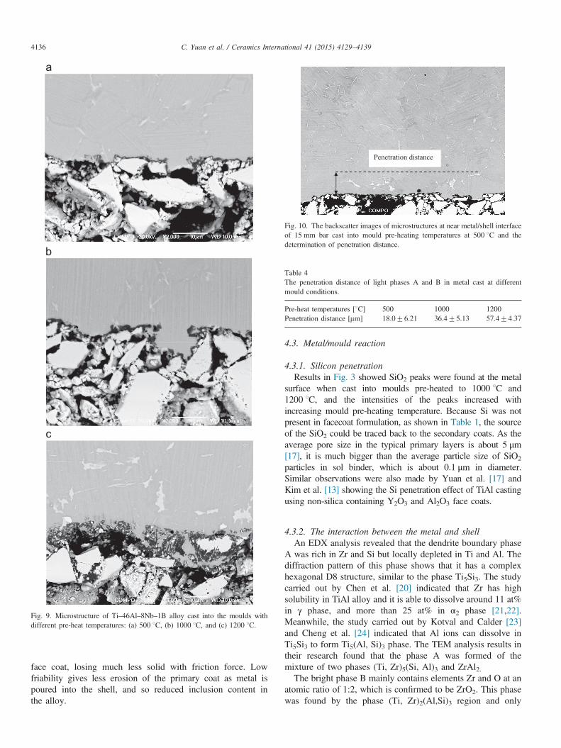
Fig. 9. Microstructure of Ti–46Al–8Nb–1B alloy cast into the moulds withdifferent pre-heat temperatures: (a) 500 1C, (b) 1000 1C, and (c) 1200 1C.
Penetration distance
Fig. 10. The backscatter images of microstructures at near metal/shell interfaceof 15 mm bar cast into mould pre-heating temperatures at 500 1C and thedetermination of penetration distance.
Table 4The penetration distance of light phases A and B in metal cast at differentmould conditions.
Pre-heat temperatures [1C] 500 1000 1200Penetration distance [mm] 18.076.21 36.475.13 57.474.37
C. Yuan et al. / Ceramics International 41 (2015) 4129–41394136
face coat, losing much less solid with friction force. Lowfriability gives less erosion of the primary coat as metal ispoured into the shell, and so reduced inclusion content inthe alloy.
4.3. Metal/mould reaction
4.3.1. Silicon penetrationResults in Fig. 3 showed SiO2 peaks were found at the metal
surface when cast into moulds pre-heated to 1000 1C and1200 1C, and the intensities of the peaks increased withincreasing mould pre-heating temperature. Because Si was notpresent in facecoat formulation, as shown in Table 1, the sourceof the SiO2 could be traced back to the secondary coats. As theaverage pore size in the typical primary layers is about 5 μm[17], it is much bigger than the average particle size of SiO2
particles in sol binder, which is about 0.1 μm in diameter.Similar observations were also made by Yuan et al. [17] andKim et al. [13] showing the Si penetration effect of TiAl castingusing non-silica containing Y2O3 and Al2O3 face coats.
4.3.2. The interaction between the metal and shellAn EDX analysis revealed that the dendrite boundary phase
A was rich in Zr and Si but locally depleted in Ti and Al. Thediffraction pattern of this phase shows that it has a complexhexagonal D8 structure, similar to the phase Ti5Si3. The studycarried out by Chen et al. [20] indicated that Zr has highsolubility in TiAl alloy and it is able to dissolve around 11 at%in γ phase, and more than 25 at% in α2 phase [21,22].Meanwhile, the study carried out by Kotval and Calder [23]and Cheng et al. [24] indicated that Al ions can dissolve inTi5Si3 to form Ti5(Al, Si)3 phase. The TEM analysis results intheir research found that the phase A was formed of themixture of two phases (Ti, Zr)5(Si, Al)3 and ZrAl2.The bright phase B mainly contains elements Zr and O at an
atomic ratio of 1:2, which is confirmed to be ZrO2. This phasewas found by the phase (Ti, Zr)2(Al,Si)3 region and only

300
400
500
600
10 100 1000
Hv
(25g
)
Distance from interface (um)
pre-heating 500C
300
350
400
450
500
550
600
10 100 1000
Hv
(25g
)
Distance from interface (um)
pre-heating 1000C
300
400
500
600
700
800
900
1000
1100
1200
10 100 1000
Hv
(25g
)
Distance from interface (um)
Pre-heating 1200C
Fig. 11. The hardness of the metal measured from the mould/metal interface to600 mm depth, for a mould pre-heat temperature of (a) 500 1C, (b) 1000 1C,and (c) 1200 1C.
C. Yuan et al. / Ceramics International 41 (2015) 4129–4139 4137
appeared in the alloy cast in the mould pre-heated to 1200 1C.Previous work [25,26] showed that the zirconia on the mouldcould be dissolved by liquid metal at high temperature,releasing Zr and O which diffused into the metal. The ZrO2
dissolution speed becomes much slower when solidificationstarts. As the solidification time increases with preheattemperature, as described in the previous section, the Zr andO concentration will be higher in the alloy cast in the mouldpre-heated to 1200 1C. Due to the negative Gibbs formationenergy of ZrO2, Zr in the ZrAl2 and (Ti, Zr)5Si3 phase regioncould be re-precipitated to form the more energeticallyfavourable ZrO2 when a certain amount of O was diffusedinto TiAl alloys.The EDX analysis identified the phase C as Al2O3, and it
appeared as a continuous film structure forming at the metal/mould interface. This phenomenon was also observed byBarbosa et al. [4] in TiAl alloys interface cast in ZrO2 mould.According to Ellingham diagrams, when the temperaturereaches 750 1C and the solidification has already taken place,Al2O3 has higher thermal chemical inertness than ZrO2, andthe chemical reaction between Al in the TiAl and ZrO2 facecoat can be expected as following [27]:
2Al ðin TiAlÞþ1:5ZrO2 ¼Al2O3þ1:5 Zr ðin TiAlÞ ð5ÞThis reaction leads to the development of a thin oxide layer
on metal/mould interface shown in Fig. 9.
4.3.3. The influence of mould pre-heat temperatureSimulation of metal cooling profiles shows that a signifi-
cantly longer time is required for metal to solidify withincreasing mould pre-heat temperature, therefore the longertime for the metal and mould interaction and element diffusion.The increased hardness of the metal close to the interfacialregion at higher pre-heat casting temperature is likely to berelated to the increased oxygen in the same region [28]. Due tothe dissolving of ZrO2 during casting, Zr and O from the facecoat were diffused into the metal and the diffusion speedbecame much slower once solidification began. Therefore thediffusion distance of the oxygen increased with the longersolidification times, resulting in an increased oxygen-hardenedlayer thickness with elevated mould preheat temperatures. Thediffusion distance of elemental O is deeper than the Zrdiffusion distance due to the smaller size of the O atom.Therefore the thickness of the hardened layer is larger incomparison to the reaction layer in the metal. A significantlyhigher hardness value at the surface of the metal cast into themould pre-heated at 1200 1C was likely to be related tothe forming of the Al2O3 oxide layer, which increased from1–2 μm thick at 500 1C and 1000 1C mould preheat tempera-tures to 15 mm thick at 1200 1C.
5. Conclusion
A mould with ZrO2 face-coat was successfully developed withstable slurry properties including pH, viscosity and plate weight.The mechanical properties of the zirconia system were comparablewith standard zircon/silica based mould system with an improvedpermeability favourable for liquid metal casting of TiAl. Thefriability of the zirconia face coat was much improved incomparison with that of yttria face coat used in casting ofgamma TiAl.
C. Yuan et al. / Ceramics International 41 (2015) 4129–41394138
The effects of the mould pre-heat temperatures on mould fillingand surface condition were also studied. Low mould pre-heattemperature of 500 1C results in a non-filled bar, and the metalfilling was much improved by increasing mould pre-heat tempera-ture to over 1000 1C. However, a higher mould pre-heat tempera-ture also promoted Si penetration from the backup layer to the facecoat, resulting in a reaction within the metal during the castingprocess. This was coupled with the longer metal solidification timewithin high preheat mould that accelerated the diffusion of mouldmaterial such as Zr, Si and O into the alloy. The computersimulation of metal cooling profiles at various preheat temperaturesrevealed that, by increasing the mould from 500 1C to 1000 1C and1200 1C, the metal solidification time of a 15 mm bar increasedfrom 5 s to 20 s to 50 s, which was also confirmed by Zhao, andOliveira [26,4]. The longer contacting time of molten metals andceramic shell increased the severity of reaction between metal andceramic mould.
Microstructural analysis showed that there were threeinteraction products found in cast metal, which included agrain boundary combined of (Ti, Zr)5(Si, Al)3 and ZrAl2phases along with a precipitated ZrO2 phase at 1200 1C, andAl2O3 phase presented as a continuous layer at the metal/mould interface. The depths of the reaction layer increasedwith preheat temperatures, giving 18.0 μm at 500 1C, 36.4 μmat 1000 1C and 57.4 μm at 1200 1C.
The increased mould pre-heat temperatures also had a significanteffect on the hardness value at metal surface which was related toincreased oxygen content. The thickness of the hardened layerincreased from 100 μm at 500 1C and 1000 1C mould pre-heattemperatures to 150 mm at 1200 1C mould pre-heat temperature.The high surface hardness values corresponded to the thickerAl2O3 oxide layer at the higher pre-heat mould temperatures,giving an average of 480 Hv using 500 1C mould pre-heattemperature, 500 Hv using a 1000 1C mould pre-heat temperatureand 1150 Hv using a 1200 1C mould pre-heat temperature. Thethickness of the Al2O3 oxide layer was about 1–2 μm at both500 1C and 1000 1C, and increased to 15 μm using a 1200 1Cmould pre-heat temperature.
The computer simulation of the metal cooling profiles revealedthat, by increasing the mould from 500 1C to 1000 1C and1200 1C, the metal solidification time of a 15 mm bar at 150 μmaway from the interface increased from 5 s to 20 s and to 47 s. Thelonger contact time between the molten metal and ceramic shellincreased the severity of the reaction between metal andceramic mould.
Considering the metal cast properties and the interactiontaking place, the paper suggests that the mould pre-heattemperature should be less than 1200 1C.
Acknowledgements
The authors gratefully acknowledge the financial assistanceof the UK Engineering and Physical Sciences ResearchCouncil (EP/G034907/1) and the support of Rolls-Royce plcfor this work.
References
[1] H.B. Bomberger, F.H. Froes, P.H. Morton, Titanium—a historicalperspective, Titanium Technology: Present Status and Future Trends,in: F.H. Froes, D. Eylon, N.B. Bomberger (Eds.), Titanium DevelopmentAssociation, Ohio, Dayton, 1985, pp. 3–17.
[2] Y.-W. Kim, H. Clemens, A.H. Rosenberger, in: Gamma TitaniumAluminides, The Minerals, Metals & Materials Society (TMS), USA,ISBN 0-87339-543-3, 2003.
[3] A. Karwinski, J. Stachanczyk, K. Zapalska-Nowak, Titanium casting,Foundry Trade J. 169 (1995) 566–570.
[4] J. Barbosa, H. Puga, C.S. Ribeiro, O.M.N.D. Teodoro, A.C. Monteiro,Characterisation of metal/mould interface on investment casting ofc-TiAl, Int. J. Cast Mater. Res. 19 (6) (2006) 331–338.
[5] S. Jones, P.M. Marquis, The role of silica based binders in investmentcasting, Br. Ceram. Trans. 94 (1995) 68–73.
[6] R.C. Feagin, Casting of reactive metals into ceramic moulds, in:Proceedings of the 6th World Conference on Investment Casting,Washington, USA, 1984, paper 4.
[7] Y. Kobayashi, F. Tsukihashi, Thermodynamics of yttrium and oxygen inmolten Ti, Ti3Al, and TiAl, Metall. Mater. Trans. B 29 (1998)1037–1042.
[8] Q. Jia, Y.Y. Cui, R. Yang, Intensified interfacial reactions betweengamma titanium aluminide and CaO stabilised ZrO2, Int. J. Cast Met.Res. 17 (2004) 23–28.
[9] K.F. Lin, C.C. Lin, Interfacial reactions between Ti–6Al–4V alloy andzirconia mold during casting, J. Mater. Sci. 34 (1999) 5899–5906.
[10] J. Mi, R.A. Harding, M. Wickins, J. Campbell, Entrained oxide films inTiAl castings, Intermetallics (2003) 377–385.
[11] M.T. Jovanovic, B. Dimicic, I. Bobic, S. Zec, V. Maksimovic, Micro-structure and mechanical properties of precision cast TiAl turbochargerwheel, J. Mater. Process. Technol. 167 (2005) 14–21.
[12] M.-G. Kim, Y.-J. Kim, Investigation of interface reaction between TiAlalloys and mold materials, Met. Mater. Int. 8 (2002) 289–293.
[13] M.-G. Kim, S.-Y. Sung, Y.-J. Kim, Microstructure, metal–mold reactionand fluidity of investment cast—TiAl alloys, Mater. Trans. 45 (2004)536–541.
[14] M.T. Jovanović, I. Bobić, Z. Mišković, S. Zec, Precision Cast Ti-basedalloys—microstructure and mechanical properties, J. Metall. 15 (2009)53–69.
[15] C. Cagran, B. Wilthan, G. Pottlacher, B. Roebuck, M. Wickins,R.A. Harding, Thermophysical properties of a Ti–44%Al–8%Nb–1%Balloy in the solid and molten states, Intermatalics 11 (2003) 1327–1334.
[16] R.A. Harding, R.F. Brooks, G. Pottlacher, J. Brillo, in: Y.W. Kim,H. Clemens, A.H. Rosenberger (Eds.), Gamma Titanium Aluminides, 75,TMS, Warrendale, PA, 2003.
[17] C. Yuan, D. Compton, X. Cheng, N. Green, P.A. Withey, The influenceof polymer content and sintering temperature on yttria face-coat mouldsfor TiAl casting, J. Eur. Ceram. Soc. 32 (2012) 4041–4049.
[18] C. Yuan, P.A. Withey, S. Blackburn, Effect of the incorporation of azirconia layer upon the physical and mechanical properties of investmentcasting ceramic shell, Mater. Sci. Technol. 29 (2013) 30–35.
[19] S. Connolly, S. Jones, P.M. Marquis, Mould non-fill in thin walledcastings, Foundry Trade J. 172 (1998) 436–440.
[20] X.F. Chen, R.D. Reviere, B.F. Oliver, C.R. Brooks, The site location ofZr atoms dissolved in TiAl, Scr. Metall. Mater. 27 (1992) 45–49.
[21] R. Yang, Y.L. Hao, Y. Song, Z.X. Guo, R. Yang, Y.L. Hao, Z.-X. Guo,Site occupancy of alloying additions in Ti aluminides and its applicationto phase equilibrium evaluation, Z. Metallkunde 91 (2000) 296–301.
[22] L. Tretyachenko, Al–Ti–Zr (Aluminium–Titanium–Zirconium), in:G. Effenberg, S. Ilyenko (Eds.), Light Metal Systems, Springer, Berlin,Heidelberg, 2006, pp. 1–14 (Part 4).
[23] P.S. Kotval, R.W. Calder, In situ identification of the silicide phase insuper-α titanium alloys, Metall. Trans. 3 (1972) 1308–1311.
[24] X. Cheng, X.D. Sun, C. Yuan, N.R. Green, P.A. Withey, An Investiga-tion of a TiAlO based refractory slurry face coat system for theinvestment casting of Ti–Al alloys, Intermetallics 29 (2012) 61–69.

C. Yuan et al. / Ceramics International 41 (2015) 4129–4139 4139
[25] R.L. Saha, T.K. Nandy, R.D.K. Misra, K.T. Jacob, Evaluation of thereactivity of titanium with mould materials during casting, Bull. Mater.Sci. 12 (1989) 481–493.
[26] R.L. Saha, T.K. Nandy, R.D.K. Misra, K.T. Jacob, On the evaluation ofstability of rare earth oxides as face coats for investment casting oftitanium, Metall. Mater. Trans. B 21 (1990) 559–566.
[27] R.A. Swalin, in: Thermodynamics of Solids, John Wiley & Sons, USA,1972.
[28] J. Barbosa, C.S. Ribeiro, A.C. Monteiro, Influence of superheating oncasting of γ-TiAl, Intermetallics 15 (2007) 945–955.