Chakana Copper - excellent copper/gold/silver project in Peru
i
INVESTIGATIONS ON SILVER-COPPER
NANOPASTE AS DIE-ATTACH MATERIAL FOR
HIGH TEMPERATURE APPLICATIONS
TAN KIM SEAH
UNIVERSITI SAINS MALAYSIA
2015

ii
INVESTIGATIONS ON SILVER-COPPER
NANOPASTE AS DIE-ATTACH MATERIAL FOR
HIGH TEMPERATURE APPLICATIONS
by
TAN KIM SEAH
Thesis submitted in fulfillment of the requirements
for the Degree of
Doctor of Philosophy
JANUARY 2015

iii
PENGISYTIHARAN / DECLARATION
Saya isytiharkan bahawa kandungan yang dibentangkan di dalam tesis ini adalah
hasil kerja saya sendiri dan telah dijalankan di Universiti Sains Malaysia kecuali
dimaklumkan sebaliknya.
I declare that the contents presented in this thesis are my own work which was done
at Universiti Sains Malaysia unless stated otherwise. The thesis has not been
previously submitted for any other degree.
Tandatangan Calon /
Signature of Candidate
Tandatangan Penyelia /
Signature of Supervisor
Nama Calon / Name of Candidate
TAN KIM SEAH
Nama Penyelia & Cop Rasmi /
Name of Supervisor & Official Stamp
PROFESSOR IR. DR.
CHEONG KUAN YEW
Tarikh / Date
JANUARY 2015
Tarikh / Date
JANUARY 2015
ii
ACKNOWLEDGEMENTS
I would like to take this opportunity to express my heartiest gratitude to the
following people for their invaluable help rendered during my Ph.D journey.
First and foremost, I would like to express my sincere thanks to my
supervisor, Professor Ir. Dr. Cheong Kuan Yew, for his invaluable advice, support,
and patience throughout the research studies. His guidance, advises encouragement,
and constructive suggestions enabled me to handle the project well.
I also want to express my gratitude to the Dean, Professor Dr. Hanafi Ismail
and all academic and administrative staffs of the School of Materials and Mineral
Resources Engineering for their continual assistance and supports.
I would like to express my sincere thanks to Mr. Mohd Suhaimi Sulong,
Mdm. Fong Lee Lee, Mr. Mohd Azam, Mr. Mokhtar and all technical staffs, for
their patience in guiding me during the study. Also, I would like to thank to all
technical staffs from Nano-optoelectronic Research (N.O.R) lab of the School of
Physics. This research would be nothing without the enthusiasm and assistance from
them.
I am deeply indebted to my colleagues-cum-friends associated in Electronic
Materials Research Group, especially Khor Li Qian, Quah Hock Jin, Lim Way

iii
Foong, Vemal Raja Manikam, Mohammad Saleh Gorji, Tan Pi Lin and Lim Zhe Xi,
for their invaluable supports and suggestions throughout the project.
A great appreciation is dedicated to my loved family members, especially my
parents and brothers, for their love, unfailing encouragement and support.
Last but not least, I would like to acknowledge the financial assistance
provided by Universiti Sains Malaysia via Research University Postgraduate
Research Grant Scheme (USM-RU-PRGS), and Ministry of Education Malaysia via
MyPhD scholarship program.
iv
TABLE OF CONTENTS
Page
ACKNOWLEDGEMENTS ii
TABLE OF CONTENTS iv
LIST OF TABLES x
LIST OF FIGURES xii
LIST OF ABBREVIATIONS xix
LIST OF SYMBOLS xxi
LIST OF PUBLICATIONS xxiii
ABSTRAK xxv
ABSTRACT
xxvii
CHAPTER 1: INTRODUCTION
1.1 Theoretical Background
1.2 Problem Statement
1.3 Research Objectives
1.4 Scope of Study
1.5 Thesis Outline
1
3
9
10
11
CHAPTER 2: LITERATURE REVIEW
2.1 Introduction
2.2 Definition of High-Temperature for Electronic Device
2.3 Evolution of Semiconductor in Electronic Device
2.3.1 Demands of High-Temperature Electronic Device
2.4 An Overview of Electronic Packaging
13
14
14
17
22

v
2.5 Materials for Level-One Electronic Packaging
2.5.1 Requirements for High-Temperature Die-Attach
Materials
2.6 Classification of Die-Attach Materials
2.6.1 Conductive Adhesive
2.6.2 Conductive Glass
2.6.3 Solder Alloy
2.6.3.1 Tin Based Solder Alloy (Lead-Bearing and
Lead-Free)
2.6.3.2 Gold Based Solder Alloy
2.6.3.3 Bismuth Based Solder Alloy
2.6.3.4 Zinc Based Solder Alloy
2.6.4 Metal Film
2.6.5 Metal Paste
2.7 Factors Affecting Properties of Die-Attach Materials
2.7.1 Interfaces
2.7.2 Defects
2.8 Ag-Cu system
2.9 Nanoparticles
2.10 Sintering of Nanoparticles
2.11 Organic Additives for Nanopaste Formulation
2.12 Summary
23
25
32
32
35
38
39
44
49
53
60
62
73
74
77
79
82
84
88
89
vi
CHAPTER 3: MATERIALS AND METHODOLOGY
3.1 Introduction
3.2 Materials
3.2.1 Materials for Ag-Cu Nanopaste Formulation
3.2.2 Substrate Materials
3.2.3 Materials for Substrate Cleaning
3.2.4 SiC Die
3.2.5 Materials for SiC Die Cleaning
3.2.6 Materials for SiC Die and Substrate Metallization
3.3 Experimental Procedures
3.3.1 Substrate Cleaning Process
3.3.2 Formulation of Ag-Cu Nanopaste
3.3.3 Stencil Printing of the Ag-Cu Nanopaste
3.3.4 Sintering of the Ag-Cu Nanopaste
3.3.5 SiC Die Cleaning Process
3.3.6 Metallization Coating for SiC Die and Cu Substrate
3.3.7 Thermal Aging Test on Sintered Nanopaste
3.3.8 Cross-Section Failure Analysis
3.4 Characterization Techniques
3.4.1 Physical Characterization
3.4.1.1 Field Emission Scanning Electron Microscopy
(FE-SEM)
3.4.1.2 Energy-Filtered Transmission Electron
Microscopy (EF-TEM)
3.4.1.3 Atomic Force Microscopy (AFM)
91
94
94
95
95
96
96
96
97
97
98
100
101
103
105
106
107
108
108
108
108
109

vii
3.4.1.4 X-Ray Diffraction (XRD)
3.4.1.5 Rheological Study
3.4.1.6 Density and Porosity
3.4.1.7 Carbon-Hydrogen-Nitrogen-Surfur (CHNS)
Elemental Analysis
3.4.2 Electrical Characterization
3.4.3 Thermal Characterization
3.4.3.1 Differential Scanning Calorimetry (DSC)
3.4.3.2 Thermogravimetric Analysis (TGA)
3.4.3.3 Thermomechanical Analysis (TMA)
3.4.3.4 Nanoflash Laser
3.4.4 Mechanical Characterization
3.4.4.1 Nanoindentation
3.4.4.2 Lap Shear Test
109
109
110
111
111
112
112
113
113
114
115
115
115
CHAPTER 4: RESULTS AND DISCUSSION
4.1 Introduction
4.2 Formulation of Ag-Cu Nanopaste
4.2.1 Determination of the Characteristics of Ag and Cu
Nanoparticles
4.2.2 Determination of the Characteristics of Organic
Additives
4.2.3 Rheological Properties of Ag-Cu Nanopaste With
Various Nanoparticle Loadings
4.3 Determination of Sintering Temperature for Ag-Cu Nanopaste
117
118
118
122
124
127

viii
4.3.1 Physical and Electrical Characteristics
4.4 Determination of Sintering Environment for Ag-Cu Nanopaste
4.4.1 Physical and Electrical Characteristics
4.5 Investigation of Physical and Electrical Characteristics of Ag-Cu
Nanopaste With Various Cu Loadings
4.5.1 Rheological Properties
4.5.2 XRD Analysis
4.5.3 Density and Porosity Analysis
4.5.4 Surface Morphology Analysis
4.5.5 Electrical Conductivity Measurements
4.5.6 Summary
4.6 Investigation of Thermal Characteristics of Ag-Cu Nanopaste With
Various Cu Loadings
4.6.1 Melting Point and Safety Operating Temperature
4.6.2 Specific Heat, Thermal Diffusivity and Thermal
Conductivity
4.6.3 Thermal Expansion
4.6.4 Summary
4.7 Investigation of Mechanical Characteristics of Ag-Cu Nanopaste
With Various Cu Loadings
4.7.1 Hardness, Young’s Modulus and Stiffness
4.7.2 Bonding Attributes of Ag-Cu Nanopaste
4.7.3 Thermal Shock Resistance
4.7.4 Summary
4.8 Investigation of the Bonding Attributes on Different Metallizations
127
132
132
136
137
140
143
144
149
152
153
153
157
165
176
176
177
184
187
189
193
ix
4.8.1 Effect of Metallization on Bonding Attributes
4.9 Application of Ag-Cu Nanopaste and Its Adhesion Performance
After Thermal Aging
193
198
CHAPTER 5: CONCLUSION AND FUTURE RECOMMENDATIONS
5.1 Conclusion
5.2 Recommendations For Future Work
204
206
REFERENCES
APPENDICES
207
226

x
LIST OF TABLES
Page
Table 1.1 Benchmark requirements of various die-attach properties
for SiC device
2
Table 1.2 Properties of bulk Ag, Cu, Au and Al
8
Table 2.1 A comparison of semiconductor properties between Si
and SiC
16
Table 2.2 Automotive maximum operating temperatures
20
Table 2.3 A summary of various gases sensed by SiC-based gas
sensors
24
Table 2.4 Summary properties of conductive adhesive
35
Table 2.5 Summary properties of conductive glass
37
Table 2.6 Eutectic temperature of various Sn based binary solder
alloys
41
Table 2.7 Melting temperature of various Pb-free Sn based ternary
and quaternary solder alloys and composites
42
Table 2.8 Summary properties of Au-20Sn, Au-12Ge and Au-3Si
eutectic solder alloys
48
Table 2.9 Summary properties of various Bi based solder alloys
49
Table 2.10 Solidus and liquidus temperatures of various Zn based
solder alloys
53
Table 2.11 Summary properties of various Zn based solder alloys
59
Table 2.12 Summary properties of various metal pastes
71
Table 2.13 Selected characteristics of Ag and Cu
82
Table 2.14 Reported organic additives in nanopaste formulation
89
Table 3.1 Raw materials used for Ag-Cu nanopaste formulation
94

xi
Table 3.2 List of chemicals for substrate cleaning
96
Table 3.3 List of chemicals for SiC die cleaning
96
Table 3.4 Materials used for metallization
97
Table 3.5 Formula of Ag-Cu nanopaste with various organic
additive contents
99
Table 3.6 Step by step cleaning process for SiC die
103
Table 4.1 Weight ratio of Ag and Cu nanoparticles for pure Ag
nanopaste, pure Cu nanopaste and Ag-Cu nanopaste
137
Table 4.2 Electrical conductivity of Ag-Cu nanopaste versus
typical die-attach systems
152
Table 4.3 Thermal conductivity, CTE and performance index for
various die-attach systems
163
Table 4.4 The CTE difference between typical high-temperature
die-attach systems and electronic packaging components
171
Table 4.5 Thermal conductivity, CTE and performance index for
various dies and substrates for high-temperature
applications
175
Table 4.6 Hardness, Young’s modulus and porosity of sintered
pure Ag, pure Cu and Ag-Cu nanopastes in against bulk
Ag and Cu
183
Table 4.7 Hardness and Young’s modulus of sintered Ag-Cu
nanopaste in against typical die-attach systems
185
Table 4.8 Thermal conductivity, CTE, Young’s modulus, fracture
strength and thermal shock resistance for various die-
attach systems, dies and substrates
190
Table 5.1 Summary properties of sintered Ag-20Cu nanopaste 206

xii
LIST OF FIGURES
Page
Figure 2.1 Hierarchy of electronic packaging
23
Figure 2.2 Schematic drawing of (a) ICA and (b) ACA
33
Figure 2.3 Firing profile for conductive glass
36
Figure 2.4 Melting temperature of Sn-Pb solder alloy with
increasing of Pb loading
40
Figure 2.5 Cross-sectional SEM image of Au-20Sn solder reflowed
at 280°C for (a) 10 s and (b) 60 s. The lighter region is
Au5Sn and the darker region is AuSn
45
Figure 2.6 SEM micrograph of reflowed (a) Au-12Ge and (b) Au-
3Si solder alloys
47
Figure 2.7 Microstructure of reflowed Bi-2.5Ag and Bi-11Ag solder
alloys
50
Figure 2.8 (a) Shear strength of Bi-Ag solder alloy with various Ag
loadings; (b) a comparison of shear strength of Bi-Ag
solder alloy with and without minor addition of Ce
51
Figure 2.9 Electrical resistivity of Bi-2.6Ag-0.1Cu-(0-2)Sb solder
alloy
52
Figure 2.10 SEM micrographs of Zn-Sn solder alloy with (a) 40 wt%,
(b) 30 wt% and (c) 20 wt% of Sn loading
55
Figure 2.11 Shear strength and thermal conductivity of Zn-(20-40)Sn
in against of Au-20Sn and Pb-5Sn solder alloys
56
Figure 2.12 Shear strength of Zn-6Al-5Ge solder alloy at different
reflow temperatures in against of Pb-5Sn solder alloy
57
Figure 2.13 Shear strength of Zn-4Al-3Mg-3Ga solder alloy at
different reflow temperatures in against of Pb-5Sn solder
alloy
58
Figure 2.14 Pull strength of Au-In and Ag-In systems fir before and
after annealing processes
61

xiii
Figure 2.15 Formulation steps of Ag nanopaste
65
Figure 2.16 (a) Shear strength of Cu nanopaste that sintered at
various temperatures and pressures; (b) shear strength of
Cu nanopaste that sintered at various temperatures and
environments
67
Figure 2.17 Bonding shear strength as a function of sintering
temperature. Dashed line represents Ag micropaste and
solid line represents Ag hybrid paste
69
Figure 2.18 Shear strength, porosity and thermal conductivity of Ag
hybrid paste that sintered under different combinations of
dwell time and pressure
70
Figure 2.19 Schematic diagram of a semiconductor die attached on a
substrate using die-attach material
74
Figure 2.20 (a) Intermetallic formation of Sn solder alloy; (b)
grooving of Bi-Ag solder alloy; and (c) atomic diffusion
of Ag metal paste
75
Figure 2.21 The silver-copper phase diagram
80
Figure 2.22 Melting temperature for Ag and Cu as a function of
particle size
83
Figure 2.23 Atomic transport paths during sintering
85
Figure 2.24 Illustration of the sintering stages
86
Figure 3.1 An overview of the research methodology
92
Figure 3.2 An overview on characterization techniques used in this
work
93
Figure 3.3 AlN DBC substrate for die-attach
95
Figure 3.4 Formulation process flow for Ag-Cu nanopaste
100
Figure 3.5 Schematic cross sectional view of Ag-Cu nanopaste
stencil printed on either pre-cleaned Cu substrate or pre-
clean soda lime glass substrate
101

xiv
Figure 3.6 The experimental setup for sintering Ag-Cu nanopaste in
open air ambient
102
Figure 3.7 The experimental setup for sintering Ag-Cu nanopaste
with flow of either nitrogen or argon gas
103
Figure 3.8 Schematic cross sectional view of SiC die attached on
either bare Cu substrate or AlN DBC substrate using Ag-
Cu nanopaste
107
Figure 3.9 (a) Schematic top view configuration of a single lap
shear joint specimen, and (b) setup of the lap shear test
116
Figure 4.1 XRD diffractogram for as-received commercial Ag and
Cu nanoparticles
119
Figure 4.2 Particle size distribution for as-received commercial Ag
and Cu nanoparticles
119
Figure 4.3 DSC thermograph for as-received commercial Ag and Cu
nanoparticles
120
Figure 4.4 TGA thermograph for as-received commercial Ag and
Cu nanoparticles
121
Figure 4.5 TEM image of Ag and Cu nanoparticles that covered by
a thin layer of ethylene glycol
123
Figure 4.6 TGA thermogram for various organic additives used in
nanopaste
124
Figure 4.7 Flow curve for Ag-20Cu nanopaste with various loadings
of nanoparticle
125
Figure 4.8 The appearance of Ag-20Cu nanopaste with various
loadings of nanoparticle; (a) ≤ 87 wt%, (b) 88 wt% and
(c) 89 wt%
126
Figure 4.9 FE-SEM micrographs of Ag-20Cu nanopaste sintered at
open air and various sintering temperatures
128
Figure 4.10 XRD diffractogram of Ag-20Cu nanopaste sintered at
open air and various sintering temperatures
130

xv
Figure 4.11 Electrical conductivity of Ag-20Cu nanopaste sintered at
open air and various sintering temperatures
131
Figure 4.12 XRD diffractogram of Ag-20Cu nanopaste sintered with
various sintering environments and temperature of 380°C
133
Figure 4.13 Carbon content of Ag-20Cu nanopaste sintered with
various sintering environments and temperature of 380°C
134
Figure 4.14 FE-SEM micrographs of Ag-20Cu nanopaste that
sintered in (a) open air, (b) nitrogen and (c) argon
ambient
135
Figure 4.15 Electrical conductivity of Ag-20Cu nanopaste sintered
with various sintering environments and temperature of
380°C.
136
Figure 4.16 (a) Schematic of organic binder that linked-up the
nanoparticles with surfactant coating, (b) typical
appearance of Ag-Cu nanopaste with desired stencil
printable quality
138
Figure 4.17 Flow curve for pure Ag nanopaste (0 wt% Cu), pure Cu
nanopaste (100 wt% Cu) and Ag-Cu nanopaste with
various Cu loadings (20-80 wt%)
139
Figure 4.18 XRD diffractogram for sintered pure Ag nanopaste (0
wt% Cu), sintered pure Cu nanopaste (100 wt% Cu) and
sintered Ag-Cu nanopaste with various Cu loadings (20-
80 wt% Cu) and for as-received raw Ag and Cu
nanoparticles
141
Figure 4.19 Density and porosity error bar plot for sintered pure Ag
nanopaste (0 wt% Cu), sintered pure Cu nanopaste (100
wt% Cu) and sintered Ag-Cu nanopaste with various Cu
loadings (20-80 wt% Cu) (the spherical symbols in plot
represent mean values)
143
Figure 4.20 FE-SEM micrographs for pure Ag nanopaste (0 wt%
Cu), pure Cu nanopaste (100 wt% Cu) and Ag-Cu
nanopaste with various Cu loadings (20-80 wt%) that
sintered at temperature of 380°C and open air ambient
145
xvi
Figure 4.21 AFM micrographs for pure Ag nanopaste (0 wt% Cu),
sintered Cu nanopaste (100 wt% Cu) and Ag-Cu
nanopaste with various Cu loadings (20-80 wt%) that
sintered at temperature of 380°C and open air ambient
147
Figure 4.22 Mean grain size and surface roughness (RMS) for
sintered pure Ag nanopaste (0 wt% Cu), sintered pure Cu
nanopaste (100 wt% Cu) and sintered Ag-Cu nanopaste
with various Cu loadings (20-80 wt%)
148
Figure 4.23 Electrical conductivity for sintered pure Ag nanopaste (0
wt% Cu), sintered pure Cu nanopaste (100 wt% Cu) and
sintered Ag-Cu nanopaste with various Cu loadings (20-
80 wt%) (the spherical symbols in the error bar represent
mean values)
150
Figure 4.24 DSC curves for sintered pure Ag nanopaste (0 wt% Cu),
sintered pure Cu nanopaste (100 wt% Cu) and Ag-Cu
nanopaste with various Cu loadings (20-80 wt% Cu).
Inset resolves the overlapped curves
154
Figure 4.25 Melting temperature of various die-attach systems and
their operational temperature range
156
Figure 4.26 (a) DSC heat flow curves for empty pan baseline, Ag
reference standard, sintered pure Ag nanopaste (0 wt%
Cu), sintered pure Cu nanopaste (100 wt% Cu) and
sintered Ag-Cu nanopaste with various Cu loadings (20-
80 wt% Cu); (b) specific heat for sintered pure Ag
nanopaste (0 wt% Cu), sintered Cu nanopaste (100 wt%
Cu) and sintered Ag-Cu nanopaste with increasing of Cu
loading (20-80 wt% Cu)
158
Figure 4.27 Thermal diffusivity for sintered pure Ag nanopaste (0
wt% Cu), sintered pure Cu nanopaste (100 wt% Cu) and
sintered Ag-Cu nanopaste with increasing of Cu loading
(20-80 wt% Cu) at temperature 25, 150 and 300°C
159
Figure 4.28 Thermal conductivity for sintered pure Ag nanopaste (0
wt% Cu), sintered pure Cu nanopaste (100 wt% Cu) and
sintered Ag-Cu nanopaste with increasing of Cu loading
(20-80 wt% Cu) at temperature 25, 150 and 300°C
161

xvii
Figure 4.29 (a) Thermal expansion as a function of temperature plot
and (b) transition temperature of thermal expansion for
sintered pure Ag nanopaste (0 wt% Cu), sintered pure Cu
nanopaste (100 wt% Cu) and sintered Ag-Cu nanopaste
with various Cu loadings (20-80 wt%)
166
Figure 4.30 Coefficient of thermal expansion (CTE) plot for sintered
pure Ag nanopaste (0 wt% Cu), sintered pure Cu
nanopaste (100 wt% Cu) and sintered Ag-Cu nanopaste
with various Cu loadings (20-80 wt%)
167
Figure 4.31 Illustration of shrinkage of pore to accommodate the
thermal expansion with rising temperature up to
transition temperature (enlarges are the illustrations for
the increment of inter-atomic distance with rising
temperature)
169
Figure 4.32 Thermal conductivity plotted against CTE for various
die-attach systems
172
Figure 4.33 Indentation hysteresis of sintered pure Ag nanopaste (0
wt% Cu), sintered pure Cu nanopaste (100 wt% Cu) and
sintered Ag-Cu nanopaste with various Cu loadings (20-
80 wt%)
178
Figure 4.34 Hardness of sintered pure Ag nanopaste (0 wt% Cu),
sintered pure Cu nanopaste (100 wt% Cu) and sintered
Ag-Cu nanopaste with various Cu loadings (20-80 wt%)
181
Figure 4.35 Stiffness of sintered pure Ag nanopaste (0 wt% Cu),
sintered pure Cu nanopaste (100 wt% Cu) and sintered
Ag-Cu nanopaste with various Cu loadings (20-80 wt%)
182
Figure 4.36 Young’s modulus of sintered pure Ag nanopaste (0 wt%
Cu), sintered pure Cu nanopaste (100 wt% Cu) and
sintered Ag-Cu nanopaste with various Cu loadings (20-
80 wt%)
183
Figure 4.37 (a) Lap shear stress-strain curve of strength of sintered
pure Ag nanopaste (0 wt% Cu), sintered pure Cu
nanopaste (100 wt% Cu) and sintered Ag-Cu nanopaste
with various Cu loadings (20-80 wt%)
186

xviii
Figure 4.38 Bonding strength of sintered pure Ag nanopaste (0 wt%
Cu), sintered pure Cu nanopaste (100 wt% Cu) and
sintered Ag-Cu nanopaste with various Cu loadings (20-
80 wt%)
187
Figure 4.39 Bonding strength of sintered Ag-20Cu nanopaste with
various metallization layers on Cu substrate
194
Figure 4.40 FE-SEM shear surface micrographs for shear-off joint
with various metallization layers on Cu substrate
195
Figure 4.41 FE-SEM cross sectional images for shear-off joint with
various metallization layers on Cu substrate at a different
magnification
196
Figure 4.42 FE-SEM cross sectional images for sintered nanopaste
with 20 and 80 wt% of Cu loading attached on Au-coated
Cu substrate at a different magnification
198
Figure 4.43 FE-SEM cross sectional images for Ag-coated SiC
attached on either Ag-Ni or Au-Ni AlN DBC substrate
using sintered Ag-20Cu nanopaste at different
magnifications
200
Figure 4.44 FE-SEM cross sectional images for Au-coated SiC
attached on either Ag-Ni or Au-Ni AlN DBC substrate
using sintered Ag-20Cu nanopaste at different
magnifications
201
Figure 4.45 FE-SEM cross sectional images for bare SiC attached on
either Ag-Ni or Au-Ni AlN DBC substrate using sintered
Ag-20Cu nanopaste at different magnifications
202

xix
LIST OF ABBREVIATIONS
ACA : Anisotropic conductive adhesive
AFM : Atomic force microscopy
CHNS : Carbon-hydrogen-nitrogen-sulfur
CTE : Coefficient of thermal expansion
DBC : Direct bonded copper
DI : De-ionized
DSC : Differential scanning calorimetry
EEE : Electrical and electronic equipment
EF-TEM : Energy-filtered transmission electron microscopy
EG : Ethylene glycol
FE-SEM : Field-emission scanning electron microscopy
ICA : Isotropic conductive adhesive
ICSD : Inorganic crystal structure database
IMC : Intermetallic compound
MEA : More electric aircraft
MEMS : Micro-electro-mechanical system
MOS : Metal-oxide-semiconductor
MW : Molecular weight
PWC
: Printed wiring board
RMS : Root-mean-square
RoHS : Restriction of hazardous substance
TGA : Thermo-gravimetric analysis
TMA : Thermo-mechanical analysis

xx
UV-Vis : Ultraviolet-visible spectroscopy
WEEE : Waste of electrical and electronic equipment
XRD : X-ray diffraction

xxi
LIST OF SYMBOLS
α : Coefficient of thermal expansion
β : Shape constant for a Berkovich indentation tip
ɛ : Buildup strain
ρ : Bulk density
: Theoretical density
λ : Thermal diffusivity
A : Contact area
Cp1 : Specific heat of the sintered nanopaste sample
Cp2 : Specific heat of the reference standard
E : Young’s modulus
: Young’s modulus of the Berkovich indentation tip
: Reduced Young’s modulus for sintered nanopaste
H : Hardness
h : Indentation depth
hc : penetration contact depth
hmax : Maximum indentation depth of the sintered nanopaste by an
indenter
k : Thermal conductivity
∆L : Change of the sample length
Lo : Original sample length
M : Performance index, the ratio of K/α
m1 : Mass of the sintered nanopaste sample
m2 : Mass of the reference standard
P : Applied load
xxii
Pmax : Maximum applied load by an indenter
Q : Heat flow per unit area
S : Stiffness
T : Temperature
∆T : Change of the temperature
Th : Homologue temperature ratio
Tm : Melting temperature
To : Safety operational temperature
: Poisson’s ratio of sintered nanopaste
: Poisson’s ratio of the Berkovich indentation tip
Wd : Dry weight of sintered nanopaste sample
Ws : Weight of sintered nanopaste sample upon suspended in water
Ww : Weight of sintered nanopaste sample upon removed from
water
wt% : Weight percent
x : Heat flow direction from die to substrate
y1 : Net heat flow of the sintered nanopaste sample
y2 : Net heat flow of the reference standard

xxiii
LIST OF PUBLICATIONS
International Peer-Reviewed Journals (ISI Indexed):
1. K. S. Tan and K. Y. Cheong, ―Advances of Ag, Cu, and Ag-Cu Alloy
Nanoparticles Synthesized via Chemical Reduction Route‖, Journal of
Nanoparticle Research, vol. 15, pp. 1-29, 2013.
2. K. S. Tan and K. Y. Cheong, ―Physical and Electrical Characteristics of Silver-
Copper Nanopaste as Alternative Die-Attach‖, IEEE Transactions on
Components, Packaging and Manufacturing Technology, vol. 4, pp. 8-15, 2014.
3. K. S. Tan, Y. H. Wong and K. Y. Cheong, ―Thermal Characteristic of Sintered
Ag–Cu Nanopaste for High-Temperature Die-Attach Application‖, International
Journal of Thermal Sciences, vol. 87, pp. 169-177, 2015.
4. K. S. Tan and K. Y. Cheong, ―Mechanical Properties of Sintered Ag–Cu Die-
Attach Nanopaste for Application on SiC Device‖, Materials and Design, vol.
64, pp. 166-176, 2014.

xxiv
International Conference Proceedings:
1. K. S. Tan and K. Y. Cheong, ―Effect of Sintering Temperature on Silver-Copper
Nanopaste as High Temperature Die Attach Material‖, 2nd
International
Conference on Sustainable Materials Engineering (ICoSM), Bayview Beach
Resort, Penang, Malaysia, 26th
-27th
March 2013.
2. V. R. Manikam, K. S. Tan, K. A. Razak and K. Y. Cheong, ―Nanoindentation of
Porous Die Attach Materials as a Means of Determining Mechanical Attributes‖,
3rd
International Conference on Advances in Mechanical Engineering, Hotel
Equatorial, Melaka, Malaysia, 28th
-29th
August 2013.
3. K. S. Tan and K. Y. Cheong, ―Effect of Sintering Environment on Silver-Copper
Die-Attach Nanopaste‖, 36th
International Electronics Manufacturing
Technology Conference (IEMT), Renaissance Johor Bahru Hotel, Johor,
Malaysia. 11th
-13th
November 2014.

xxv
KAJIAN TERHADAP NANO-PES ARGENTUM-KUPRUM SEBAGAI
BAHAN LAMPIR-DAI UNTUK APLIKASI SUHU TINGGI
ABSTRAK
Satu nano-pes argentum-kuprum (Ag-Cu) yang dirumuskan dengan
mencampurkan nanopartikel Ag dan Cu dengan penambah organik (pelekat resin,
terpineol dan ethylene glycol) telah dihasilkan bagi diaplikasikan sebagai bahan
lampir-dai suhu tinggi. Pelbagai peratus berat nanopartikel Cu (20-80 wt%) telah
ditambahkan ke dalam nano-pes Ag-Cu, diikuti oleh pensinteran di udara terbuka
pada suhu 380°C selama 30 min tanpa bantuan tekanan luar, untuk mengkaji kesan
terhadap sifat-sifat fizikal, elektrikal, terma dan mekanikal. Nanopes tulen Ag dan
Cu turut disediakan untuk tujuan perbandingan. Keputusan belauan sinar-X
menunjukkan fasa Ag97Cu3, Ag1Cu99 dan CuO terbentuk dalam nano-pes Ag-Cu
tersinter. Kajian menunjukkan bahawa keliangan didalam nano-pes Ag-Cu tersinter
meningkat dengan peningkatan kandungan Cu. Kehadiran keliangan tersebut
membuktikan kesannya untuk mengurangkan ketumpatan, saiz bijian, keberaliran
elektrik, keberaliran haba dan pekali pengembangan haba (CTE) bagi nano-pes Ag-
Cu tersinter. Walaupun keliangan turut menjejaskan kekerasan, kekukuhan dan
modulus Young nano-pes Ag-Cu tersinter, namun aliran meningkat telah direkodkan
dengan penambahan kandungan Cu. Secara keseluruhan, nano-pes Ag-Cu dengan
kandungan 20 wt% Cu menunjukan kombinasi terbaik bagi keberaliran elektrik
[2.27 x 10⁵ (Ω-cm)
-1] dan haba [159 W/m-K]. Nilai-nilai tersebut didapati lebih
tinggi daripada kebanyakan sistem bahan lampir-dai. CTE yang rendah [13 x 10-6
/
K] yang berkait dengan nano-pes Ag-Cu tersebut memanfaatkan disebabkan ia
mengelakkan pembentukan tekanan haba serius di antara dai dan substrat. Selain itu,

xxvi
nano-pes Ag-Cu telah menunjukkan suhu lebur 955°C, yang membolehkan nano-pes
Ag-Cu dapat dipertimbangkan untuk diaplikasikan pada suhu tinggi. Bagi kajian
sifat ikatan terhadap persalutan logam, salutan Ag and Au pada substrat Cu masing-
masing telah menunjukkan kekuatan ikatan tertinggi (52.6 MPa) dan terendah (34.4
MPa) bagi nano-pes Ag-Cu. Nilai kekuatan ikatan didapati berkait rapat dengan
mikrostruktur di antara nano-pes Ag-Cu dan lapisan salutan logam pada substrat.
Akhir sekali, untuk mengaplikasikan nanopes Ag-Cu sebagai bahan lampir-dai pada
suhu tinggi, nano-pes Ag-Cu telah digunakan untuk melampirkan dai silikon karbida
(SiC) pada substrat yang disaluti oleh Ag atau Au. Keseluruhan struktur ikatan
tersebut telah lulus ujian penuaan haba pada 770°C, mikrostruktur yang telah
mengalami proses penuaan haba menunjukkan bahawa nano-pes Ag-Cu merekat
dengan baik pada dai SiC dan substrat yang disaluti Ag. Namun, perekatan nano-pes
tersebut adalah kurang memuaskan pada dai SiC dan substrat yang disaluti Au.
xxvii
INVESTIGATIONS ON SILVER-COPPER NANOPASTE AS DIE-ATTACH
MATERIAL FOR HIGH TEMPERATURE APPLICATIONS
ABSTRACT
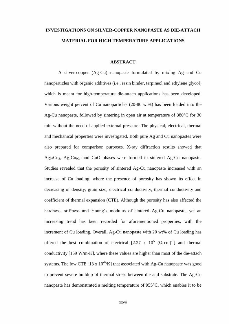
A silver-copper (Ag-Cu) nanopaste formulated by mixing Ag and Cu
nanoparticles with organic additives (i.e., resin binder, terpineol and ethylene glycol)
which is meant for high-temperature die-attach applications has been developed.
Various weight percent of Cu nanoparticles (20-80 wt%) has been loaded into the
Ag-Cu nanopaste, followed by sintering in open air at temperature of 380°C for 30
min without the need of applied external pressure. The physical, electrical, thermal
and mechanical properties were investigated. Both pure Ag and Cu nanopastes were
also prepared for comparison purposes. X-ray diffraction results showed that
Ag97Cu3, Ag1Cu99, and CuO phases were formed in sintered Ag-Cu nanopaste.
Studies revealed that the porosity of sintered Ag-Cu nanopaste increased with an
increase of Cu loading, where the presence of porosity has shown its effect in
decreasing of density, grain size, electrical conductivity, thermal conductivity and
coefficient of thermal expansion (CTE). Although the porosity has also affected the
hardness, stiffness and Young’s modulus of sintered Ag-Cu nanopaste, yet an
increasing trend has been recorded for aforementioned properties, with the
increment of Cu loading. Overall, Ag-Cu nanopaste with 20 wt% of Cu loading has
offered the best combination of electrical [2.27 x 10⁵ (Ω-cm)
-1] and thermal
conductivity [159 W/m-K], where these values are higher than most of the die-attach
systems. The low CTE [13 x 10-6
/K] that associated with Ag-Cu nanopaste was good
to prevent severe buildup of thermal stress between die and substrate. The Ag-Cu
nanopaste has demonstrated a melting temperature of 955°C, which enables it to be

xxviii
considered for high-temperature applications. For metallization and bonding
attribute studies, Ag and Au coatings on Cu substrate have displayed the highest
(52.6 MPa) and the lowest (34.4 MPa) bonding strength for Ag-Cu nanopaste,
respectively. The values of bonding strength were found to have a close relationship
with the interface microstructure between Ag-Cu nanopaste and metallization layer
on the substrate. Finally, to realize Ag-Cu nanopaste as a high-temperature die-
attach material, the Ag-Cu nanopaste was used to attach a silicon carbide (SiC) die
on a substrate with either Ag or Au coating. The entire bonding structure has passed
a three-cycle thermal aging test at 770°C. The thermal-aged interface microstructure
has shown that the Ag-Cu nanopaste was well adherence to SiC die and substrate
with Ag coating, but poor adherence to SiC die and substrate with Au coating.
1
CHAPTER 1
INTRODUCTION
1.1 Theoretical background
The demand of electronic devices that could be operated at high-temperature
(> 500°C) is continually increasing for years. This is mainly due to the advancement
of technology in various industries such as automotive, aviation, well-logging,
nuclear power plant and space exploration. These industries require electronic
devices that must not only be able to survive upon expose to high-temperature, but
they must also be able to function under such high-temperature condition. For
instance, the typical high-temperature applications for those industries are: (i) brake
and exhaust gas sensors for automotive (300-1000°C) (Johnson et al., 2004; Spetz et
al., 1999), (ii) turbine and gas sensors for aviation (~600°C) (Dreike et al., 1994;
Hunter et al., 2004; Sharp, 1999b), (iii) geothermal sensor for well-logging (~600°C)
(Neudeck et al., 2002; Sharp, 1999b; Watson and Castro, 2012), (iv) nuclear
radiation detector and nuclear reactor for nuclear plant (700-1000°C) (Dreike et al.,
1994; Kim et al., 2011; Sedlackova et al., 2013), and (v) transmitter, antenna and
electromechanical devices for space exploration (> 500°C) (Sutton, 2001). For such
demanding applications, there is an evolution of electronic device, which
transforming from silicon (Si)-based to silicon carbide (SiC)-based, due to the
former could only operate at temperature up to 250°C.
SiC-based electronic device has documented its success to operate at a
temperature exceeding 500°C. This is mainly attributed to the wide band gap
2
semiconductor properties (3.26 eV) and high breakdown field strength (3.2 MV/cm)
that associated with SiC semiconductor. These properties allow SiC semiconductor
to be operated at high-temperature without leakage of current (Chin et al., 2010).
Nevertheless, to take full advantages of SiC-based electronic device, there is a need
to develop an electronic packaging, which can use for high-temperature applications.
The main development areas of electronic packaging include die-attach material,
substrate material, wire bonding material, and encapsulation material. Of these, die-
attach material has gained particular concern as it is an integral part that provides
connection between the SiC device and the substrate.
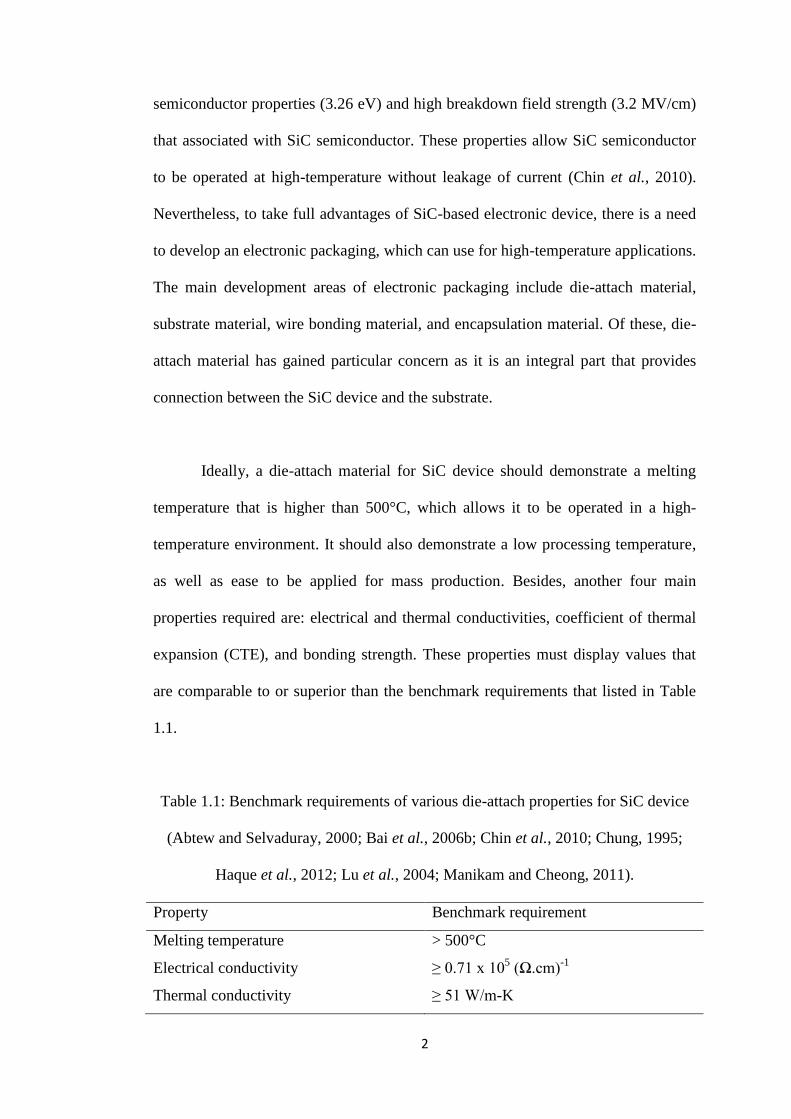
Ideally, a die-attach material for SiC device should demonstrate a melting
temperature that is higher than 500°C, which allows it to be operated in a high-
temperature environment. It should also demonstrate a low processing temperature,
as well as ease to be applied for mass production. Besides, another four main
properties required are: electrical and thermal conductivities, coefficient of thermal
expansion (CTE), and bonding strength. These properties must display values that
are comparable to or superior than the benchmark requirements that listed in Table
1.1.
Table 1.1: Benchmark requirements of various die-attach properties for SiC device
(Abtew and Selvaduray, 2000; Bai et al., 2006b; Chin et al., 2010; Chung, 1995;
Haque et al., 2012; Lu et al., 2004; Manikam and Cheong, 2011).
Property Benchmark requirement
Melting temperature > 500°C
Electrical conductivity ≥ 0.71 x 10⁵ (Ω.cm)
-1
Thermal conductivity ≥ 51 W/m-K

3
Table 1.1: Continued.
Property Benchmark requirement
Bonding strength ≥ 12.5 MPa
Coefficient of thermal expansion Close to the die and the substrate
1.2 Problem statement
Over the past decade, conductive adhesives (Gao et al., 2014; Gomatam and
Mittal, 2008; Lahokallio et al., 2014; Li and Wong, 2006; Yim et al., 2008) and tin
(Sn)-based solders alloys (lead-bearing and lead-free) (Abtew and Selvaduray, 2000;
Koo et al., 2014; Kotadia et al., 2014; Liu et al., 2008; Wu et al., 2004; Zeng et al.,
2012; Zeng and Tu, 2002; Zhang et al., 2012) have been widely used for level-one
interconnection, namely die-attach material, which serves to attach a semiconductor
die on a substrate. The wide use of conductive adhesive and Sn based solder alloys
are mainly due to the low cost and acceptable electrical conductivity [0.01-0.71 x10⁵
(Ω-cm)-1
] and thermal conductivity [1-66 W/m-K] (Abtew and Selvaduray, 2000;
Calame et al., 2005; Gao et al., 2014; Guan et al., 2010; Kisiel and Szczepański,
2009; Kotadia et al., 2014; Lewis and Coughlan, 2008; Navarro et al., 2012;
Suganuma et al., 2009). However, with the recent development of SiC device that
could be operated at temperature exceeding 500°C (Manikam and Cheong, 2011),
conductive adhesive and Sn based solder alloys that melt at a temperature below
315°C (Abtew and Selvaduray, 2000; Kotadia et al., 2014; Lahokallio et al., 2014;
Wu et al., 2004; Zeng and Tu, 2002) can no longer meet the operating temperature
requirement. The challenge is thus driven to seek a die-attach material that can be
operated at temperature higher than 500°C.

4
Bismuth (Bi) (Kim et al., 2014; Shi et al., 2010; Song et al., 2007a; Song et
al., 2006; Spinelli et al., 2014; Wang et al., 2014b), gold (Au) (Bazin et al., 2014;
Chidambaram et al., 2012; Ding et al., 2013; Huang et al., 2013; Lau et al., 2013;
Zhu et al., 2014), and zinc (Zn) (Haque et al., 2012; Haque et al., 2010; Kim et al.,
2009a; Shimizu et al., 1999) based solder alloys are next being proposed as
alternative solutions. Of these, Bi based solder alloys have generally displayed poor
electrical conductivity [0.02-0.12 x10⁵ (Ω-cm)
-1] (Kim et al., 2014; Song et al.,
2007a; Song et al., 2006), poor thermal conductivity [7-11 W/m-K] (Lalena et al.,
2002; Tschudin et al., 2002) and moderate melting point [262-361°C] (Lalena et al.,
2002; Spinelli et al., 2014; Wang et al., 2014b), which are inadequate to be
considered as alternative solutions. Au and Zn based solder alloys, although, have
displayed high thermal conductivity [27-110 W/m-K] (Bazin et al., 2014; Kim et al.,
2009a; Kisiel and Szczepański, 2009; Suganuma et al., 2009), their electrical
conductivity [0.34-0.65 x10⁵ (Ω-cm)
-1] (Bazin et al., 2014; Lau et al., 2013) and
melting point [280-383°C] (Bazin et al., 2014; Kim et al., 2008; Kim et al., 2009c;
Lau et al., 2013; Lee et al., 2005; Sheen et al., 2002; Weng et al., 2013) are still
lower than the benchmark values (Table 1.1), making them failed to be considered
as suitable die-attach materials for SiC device. Au-nickel (Ni), with its high melting
point of 980°C, is an exceptional solder alloy that meets the operating temperature
requirement (> 500°C) of SiC device, but its high soldering temperature at 980°C
has also become a drawback (Kirschman, 1999). Two new die-attachment
techniques, namely inter-diffusion bonding of metal film and sintering of metal
paste, are subsequently being introduced to overcome the weakness (i.e., high
soldering temperature) that is associated with Au-Ni solder alloy. For instance, Au-
indium (In) (Mustain et al., 2010; Welch and Najafi, 2008) and silver (Ag)-In
5
(Chuang and Lee, 2002; Mustain et al., 2010; Wu and Lee, 2013) are particular die-
attach materials that utilized inter-diffusion bonding technique to form a joint
between metal films at temperature of 206 to 210°C with pressure of 40 to 80 psi.
Meanwhile, Ag micropaste (Zhang and Lu, 2002) (i.e., a mixture of micro-sized
metal particles and organic additives) and copper (Cu) micropaste (Kahler et al.,
2012b) are particular die-attach materials that formed a joint by sintering the
micropaste at temperature of 250°C with pressure of 40 MPa. Overall, the advantage
of these die-attachment techniques is able to process at a moderate temperature
(206-250°C), yet the joint formed could be operated at temperature exceeds 495°C
(Kahler et al., 2012b; Mustain et al., 2010; Welch and Najafi, 2008; Wu and Lee,
2013; Zhang and Lu, 2002). On the other hand, application of pressure during the
process is one of the disadvantages of these die-attachment techniques, which could
complicate the manufacturing process and with slight irregularities during
application of pressure may lead to cracking of both the die and the substrate
(Kahler et al., 2012b; Mustain et al., 2010; Welch and Najafi, 2008; Wu and Lee,
2013; Zhang and Lu, 2002).
In recent years, a strategy of reducing the size of metal particle in metal paste,
from micron to nano, has been introduced, which it is named as nanopaste (i.e., a
mixture of nano-sized metal particles and organic additives). The reduction of
particle size aims to increase the chemical driving force of metal particle and thus
contributes to eliminate the application of pressure during sintering. Ag nanopaste
(Bai et al., 2007a; Bai et al., 2007b; Bai et al., 2005; Bai et al., 2006b; Chen et al.,
2008; Lu et al., 2014; Lu et al., 2009; Mei et al., 2011b, 2011c; Yu et al., 2009;
Zheng et al., 2014) and Cu nanopaste (Krishnan et al., 2012; Nishikawa et al., 2011;

6
Yamakawa et al., 2013) are the leading candidates of this strategy, where they could
be sintered at temperature of 280-400°C without the need of applying any pressure
during sintering. Positive results were obtained for these sintered nanopastes,
namely: (i) no existent of die-shifting issue as the nanopaste does not undergo
liquid-state transformation during sintering (Bai et al., 2007a; Bai et al., 2007b;
Krishnan et al., 2012); (ii) high electrical [2.50-2.60 x10⁵ (Ω-cm)
-1] and thermal
conductivity [200-240 W/m-K] (Bai et al., 2005; Bai et al., 2006b; Lu et al., 2004;
Mei et al., 2012; Zheng et al., 2014); (iii) high bonding strength [2-54 MPa] could
be attained with atomic inter-diffusion between the nanopaste and the metallization
layer on a die or substrate (Bai et al., 2007b; Nishikawa et al., 2011; Yamakawa et
al., 2013); (iv) lower Young’s modulus was detected for sintered nanopaste as
compared to bulk materials and solder alloys; this is important to reduce the build-up
of thermal stress among the die, die-attach and substrate in an operating device (Bai
et al., 2007b; Bai et al., 2005; Bai et al., 2006b; Mei et al., 2012; Zheng et al., 2014)
and (v) high melting point at 960-1083°C has meet the operating temperature
requirement of a SiC device (> 500°C) (Bai et al., 2007b; Kahler et al., 2012b; Lu et
al., 2004; Lu et al., 2014; Mei et al., 2011c; Zheng et al., 2014). Despite that, both
Ag nanopaste and Cu nanopaste are actually having their own limitations, where Ag
nanopaste has limited to its high cost and low electrochemical migration resistance
(Lu et al., 2014; Mei et al., 2011a); whereas Cu nanopaste is easy to oxidize. To
overcome the oxidation issue, additional time (1h) is needed to anneal the Cu
nanopaste in nitrogen environment (Krishnan et al., 2012; Yamakawa et al., 2013).
For these reasons, an Ag-aluminum (Al) nanopaste (Manikam et al., 2012;
Manikam et al., 2013c) is introduced, which aimed at surpassing the preceding

7
limitations of Ag nanopaste and Cu nanopaste. This Ag-Al nanopaste not only could
tailor the cost to be cheaper than that of Ag nanopaste, it also able to be sintered at
380°C in air atmosphere without the need of additional annealing process in nitrogen
environment. Ag-Al nanopaste has displayed electrical conductivity [1.01 x10⁵ (Ω-
cm)-1
] that is better than Sn, Bi, Au and Zn solder alloys [0.02-0.71 x10⁵ (Ω-cm)
-1],
but it is still worse than Cu micropaste [1.29 x10⁵ (Ω-cm)
-1], Ag micropaste [4.17
x105 (Ω-cm)
-1] and Ag nanopaste [2.50-2.60 x10
5 (Ω-cm)
-1] (Bai et al., 2005; Bai et
al., 2006b; Kahler et al., 2012b; Manikam et al., 2012; Zhang and Lu, 2002; Zheng
et al., 2014). Furthermore, Ag-Al nanopaste has also displayed thermal conductivity
[123 W/m-K] that is better than Sn, Au, Bi and Zn solder alloys [7-110 W/m-K], but
it is still worse than Ag micropaste [80-220 W/m-K] and Ag nanopaste [200-240
W/m-K] (Bai et al., 2005; Bai et al., 2006b; Kahler et al., 2012b; Manikam et al.,
2012; Zhang and Lu, 2002; Zheng et al., 2014).
Based on preceding facts, Ag-Cu nanopaste is introduced, which aimed to
overcome the weakness that associated with Ag-Al nanopaste. Cu was chosen to
replace Al in a nanopaste formulation because it has the second best electrical and
thermal conductivities among other metals (Callister, 2007), and it has coefficient of
thermal expansion that is comparable with Ag (Table 1.2), making it suitable to be
used with Ag in a nanopaste formulation. Moreover, the price of Cu is comparable
to that of Al ("Current pricing on precious, platinum, non ferrous, minor and rare
earth metals," 2013), which is able to meet the cost constraint in electronic
packaging. Although Cu and Al are ductile materials, Cu has higher tensile strength
than Al (Table 1.2) (Callister, 2007), where higher bonding strength is predicted for
Ag-Cu nanopaste if compared with Ag-Al nanopaste (Manikam et al., 2013c;

8
Morisada et al., 2010; Yan et al., 2012). Based on galvanic series, Cu has standard
electrode potential that is close to Ag if compared with Al to Ag, which minimize
the tendency of two metals, i.e., Ag and Cu, to interact galvanically, and thus
reduces the risk of galvanic corrosion (Chawla and Gupta, 1993). Ultimately, Cu has
a melting temperature that is drastically higher than that of Al; this might make the
melting temperature of Ag-Cu nanopaste become drastically higher than that of Ag-
Al nanopaste.
Table 1.2: Properties of bulk Ag, Cu, Au and Al.
Property Ag Cu Au Al Ref
Electrical
conductivity
[x 105 (Ω-cm)
-1]
6.80 6.00 4.30 3.80 (Callister, 2007)
Thermal
conductivity
[W/m-K]
428 398 315 247 (Callister, 2007)
Coefficient of
thermal
expansion
[x 10-6
/K]
19.7 17.0 14.2 23.6 (Callister, 2007)
Tensile strength
[MPa]
170 200 130 90 (Callister, 2007)
Young’s modulus
[GPa]
74 110 77 69 (Callister, 2007)
Ductility
[% elongation]
44 45 45 40 (Callister, 2007)
Melting point
[°C]
962 1085 1064 660 (Callister, 2007)
Price on March
2013 [$ US / kg]
1012.36 7.61 56717.06 1.89 ("Current pricing on
precious, platinum,
non ferrous, minor
and rare earth
metals," 2013)
Standard
electrode
potential [V]
+0.800 +0.340 +1.420 -1.662 (Callister, 2007)
9
In this work, the Ag-Cu nanopaste is formulated by mixing Ag and Cu
nanoparticles with organic additives. This nanopaste can be sintered at 380°C in
open air without the need of applying external pressure. The study covered the
detailed investigation of the physical, electrical, thermal and mechanical properties
of Ag-Cu nanopaste with various Cu loadings, as these properties are crucial for die-
attach applications. Further investigations were also carried out to assess the
workability of Ag-Cu nanopaste as a die-attach material for SiC device, which is
mainly for high-temperature applications.
1.3 Research objectives
The primary aim of this research is to formulate an Ag-Cu nanopaste that can
be used for high-temperature die-attach applications, yet it can be processed at a
low-temperature. Various physical, electrical, thermal and mechanical properties of
Ag-Cu nanopaste were systematically investigated, which include density, porosity,
electrical conductivity, thermal conductivity, coefficient of thermal expansion,
melting temperature, hardness, Young’s modulus and bonding strength. These
properties must be properly investigated in order to demonstrate the suitability of
Ag-Cu nanopaste as a die-attach material for high-temperature applications (Table
1.1). With this primary aim in mind, the following objectives are to be achieved:
1. To formulate an Ag-Cu nanopaste by mixing metallic nanoparticle and
organic additives, and determine its optimum sintering temperature and
environment.

10
2. To investigate the physical, electrical and thermal characteristics of Ag-Cu
nanopaste with various Cu loadings.
3. To investigate the mechanical properties of Ag-Cu nanopaste and its bonding
attributes on different metallization layers.
4. To apply Ag-Cu nanopaste for attaching SiC die on Cu substrate and
aluminium nitride direct bonded Cu substrate.
1.4 Scope of study
In this research work, Ag-Cu nanopaste was first formulated by mixing Ag
and Cu nanoparticles with various loadings of organic additives. The rheology of
nanopaste was next analyzed to determine an optimized formula for Ag-Cu
nanopaste. Various sintering temperatures and environments were used to sinter the
nanopaste which was aimed to obtain an optimized sintering condition. The research
was next continued to investigate the physical, electrical, thermal and mechanical
properties of Ag-Cu nanopaste with various weight percent of Cu loadings. The Ag-
Cu nanopaste with optimized properties was selected for further investigation on its
bonding attribute on different metallization coatings. Finally, the workability of Ag-
Cu nanopaste as a high-temperature die-attach material has been investigated, where
it was used to attach a SiC die on either Cu substrate or aluminium nitride direct
bonded Cu substrate. The entire bonding structure has undergone a thermal aging
test, followed by a cross-section failure analysis.
Various characterization techniques have been used in this work, where they
are classified into physical, electrical, thermal and mechanical characterizations. For

11
physical characterization, rheometer was used to reveal the viscosity of nanopaste.
Field emission scanning electron microscope (FE-SEM) and atomic force
microscope (AFM) were used to characterize the surface morphology and
topography of sintered Ag-Cu nanopaste. X-ray diffraction (XRD) was used to
identify the phases, and co-linear four point probe system was used to measure the
electrical conductivity of sintered nanopaste. For thermal characterization,
differential scanning calorimetry (DSC) was used to determine the melting
temperature of raw Ag and Cu nanoparticles. It also used to determine the melting
temperature and specific heat of sintered Ag-Cu nanopaste. Besides, thermo-
gravimetric analysis (TGA) was used to determine the burn off temperature of
organic additives used in Ag-Cu nanopaste. The thermal diffusivity and thermal
expansion attributes of sintered nanopaste were measured by using nanoflash laser
and thermo-mechanical analysis (TMA) systems, respectively. As for mechanical
characterization, nanoindentation technique was used to determine the hardness,
stiffness and Young’s modulus of sintered Ag-Cu nanopaste; whilst, lap shear test
has been performed by using Instron universal testing machine to obtain the bonding
strength of Ag-Cu nanopaste. The lap shear test was also performed on Cu substrate
with various metallization coatings in order to understand the bonding attributes of
Ag-Cu nanopaste.
1.5 Thesis outline
This thesis is organized and divided into 5 chapters. Chapter 1
provides an overview of high-temperature electronic packaging, followed by the
issues and challenges faced in the development of high-temperature die-attach

12
material, research objectives, and scope of study. Chapter 2 covers the detailed
literature review, which corresponds to the background theories adopted in the study.
Chapter 3 presents the systematic methodology that was employed in this research.
Chapter 4 focuses on the results and discussion from the characterizations. Finally,
Chapter 5 summarizes the overall findings of this study and concluded with
appropriate recommendation for future works.

13
CHAPTER 2
LITERATURE REVIEW
2.1 Introduction
In recent years, electronic devices are continually improving for high-
temperature applications, mainly due to the increasing demand from various
industries such as automotive, aviation, well-logging, nuclear power plant and space
exploration (Chin et al., 2010). These electronic devices are fabricated by using a
wide band-gap semiconductor, namely silicon carbide (SiC), which aim at
overcoming the limitation of low operating temperature (< 250°C) that exhibited by
conventional silicon (Si)-based electronic device (Chin et al., 2010). The current
research trend is thereby targeted to develop electronic packaging that is in line with
the SiC-based electronic device, which is able to operate at high-temperature. This
chapter begins by reviewing the evolution of electronic device from Si-based to SiC-
based, followed by their applications. The chapter will next cover an overview of
electronic packaging and the materials used for high-temperature applications. Since
this research is focused on developing a die-attach material, the basic requirements
of a die-attach material will be discussed. Next, the detailed literatures for high-
temperature die-attach materials will be systematically covered. Finally, this chapter
will review the factors affecting the mechanical, electrical, and thermal properties of
die-attach material.
14
2.2 Definition of high-temperature for electronic device
―High-temperature‖ is a term that subject to various interpretations, where it
can be defined as a temperature that is greatly higher than a typical standard
operating temperature (Chin et al., 2010). For instance, automotive, well logging
and space exploration industries have defined the term of ―high-temperature‖ as an
operating temperature at beyond 125°C (Johnson et al., 2004), 300°C (Palmer and
Heckman, 1978) and 500°C (Hagler et al., 2011), respectively. Hence, it is
inadequate to define the term of ―high-temperature‖ in accordance to respective
industry. The definition must be determined from a group of variety industries,
followed by taking into considerations the operating temperature of various
electronic devices in the group. Manikam and Cheong (2011) are the leading
researchers who proposed three ranges of temperature based on a group of variety
industries. ―High-temperature‖ is defined as a range of temperature that operates at
beyond 500°C; whilst, ―medium-temperature‖ and ―low-temperature‖ are defined as
another ranges of temperature that operate at 300-500°C and < 300°C, respectively
(Manikam and Cheong, 2011). In this thesis, these three ranges of temperature will
be used; whereby ―high-temperature‖ is fixed at a temperature that higher than
500°C.
2.3 Evolution of semiconductor in electronic device
Over the past decade, Si has emerged as the most widely used semiconductor
materials in electronic devices. This is mainly due to its interesting attributes, such
as (i) able to be produced in a large defect-free single crystal, (ii) able to grow a
15
stable native oxide layer (SiO2) that possesses superior dielectric properties, (iii) has
appropriate hardness that allows large wafer can be handled by either hand or
machine, (iv) able to be doped with small amount of impurities (e.g. phosphorus or
boron), which formed either n-type or p-type semiconductor, and (v) relatively
cheap in cost because of its relatively abundance in the earth crust (Chante et al.,
1998; Harper, 2003). However, with advances in technology for recent years, there
is a demand of electronic devices that could be operated at high-temperature (≥
500°C) and harsh environment. The electronic devices that based on Si
semiconductor, with a maximum operating temperature of 250°C, have become no
longer meet the requirement of high operating temperature. The low operating
temperature (≤ 250°C) of Si semiconductor is actually attributed by its narrow band-
gap (1.12 eV), in which leakage of electric current happens if it is operated at
temperature beyond 250°C (Chante et al., 1998). As a result, it is crucial to seek a
semiconductor material that is capable to operate at temperature beyond 250°C.
In recent years, SiC semiconductor, with its large band-gap (3.26 eV), has
identified as a promising candidate to overcome the limitation of Si semiconductor
in an electronic device, due to its operating temperature is drastically improved to
400°C and above. Besides that, SiC semiconductor could also display a few
advantages of Si semiconductor, such as (i) able to produce high quality single
crystal with low defect, (ii) able to grow native oxide of SiO2, and (iii) able to
selectively dope of either n-type or p-type (Friedrichs and Rupp, 2005). These
advantages are also contributing to make SiC becomes an interesting alternative
semiconductor material for high-temperature applications. Table 2.1 provides a
comparison of semiconductor properties between Si and SiC. It can be seen that the

16
SiC with large band-gap has offered a high breakdown electric field (3.2 MV/cm),
which is approximately ten times higher than that of Si (0.3 MV/cm) with narrow
band-gap. High breakdown electric field allows the SiC to be operated at a high-
temperature without leakage of current if compared to Si. The thermal conductivity
of SiC (3.7 W/cm-K) is approximately two times higher than that of Si (1.5 W/cm-
K); this is good for heat dissipation in an operating electronic device.
Table 2.1: A comparison of semiconductor properties between Si and SiC
(Chelnokov and Syrkin, 1997; Chin et al., 2010; Zolper, 1998).
Property Si SiC
Band-gap (eV) 1.12 3.26
Dielectric constant 11.80 9.66
Breakdown electric field (MV/cm) 0.3 3.2
Thermal conductivity (W/cm-K) 1.5 3.7
Saturated electron velocity (cm/s) 1 x 10⁷ 2 x 10⁷
Electron mobility (cm2/Vs) 1400 1000
Hole mobility (cm2/Vs) 600 115
Melting point (°C) 1417 2827
Physical stability Good Excellent
Process maturity Very high High
In addition, the saturated electron velocity of SiC (2 x 107 cm/s) is also two times
higher than that of Si (1 x 107 cm/s); this indicates that SiC can be operated at much
faster speed if compared to Si. A SiC semiconductor is actually made up of Si and C
atoms that held by a strong bond. The Si-C bond, in fact, is stronger than Si-Si bond
that contains within a Si semiconductor. This strong bond provides better physical
and chemical stabilities over the SiC semiconductor, which allows it to be operated
in a high-temperature and harsh environment (Chin et al., 2010).
17
2.3.1 Demands of high-temperature electronic device
Nowadays, consumer electronic products, such as personal computer, cell
phone, television and washing machine, have become an integral part in our daily
lives. These products are commonly made up of Si-based electronic device, where it
is continuously strike to decrease its feature size, increase its operating speed, and
reduce its power consumption. Normally, the consumer electronic products are
designed to be operated at temperature below 200°C; thereby Si-based electronic
device is sufficient to meet the requirements of those products.
On the other hand, the demands of industrial electronic components, such as
radiation and pressure sensors, are slightly varied to those consumer electronic
products. The industries are seeking for electronic components that are capable to be
operated at high-temperature, high-power and harsh environment. The Si-based
electronic device, with its low operating temperature (< 250°C), is therefore no
longer fulfill the requirements of industry electronic components. SiC-based
electronic device, with its high operating temperature (> 400°C), is next emerging as
a promising candidate to overcome the limitations of conventional Si-based
electronic device. For instance, the hydrocarbon sensor that made up of SiC has
proven able to operate at temperature up to about 800°C (Shields, 1996).
Over the years, the demand of high-temperature electronic devices has
shown a steady growth due to the continuous technology advances in various
industries. Oil and gas industry, in particular, is one of the leading industries that
have high demand on the high-temperature electronic devices. This industry requires

18
a lot of fairly sophisticated sensors that to be installed in vicinity to the drilling head
(Chin et al., 2010). During a well drilling operation, the sensors are used to monitor
the health of drilling head, as well as, used to measure the drilling depth as a
function of temperature. This is due to the temperature variation in earth crust,
which can be ranging up to 600°C for the deepest drilling depth that can be attained
by current drilling technology (Chin et al., 2010; Sharp, 1999b). For well logging
process (down-hole measurement), the sensors are used to acquire the down-hole
information, such as surrounding geologic formation and saturation of hydrocarbon
(oil and gas) (Watson and Castro, 2012). This information is important to determine
the amount of hydrocarbon that can be extracted from the well. Finally, during the
hydrocarbon extraction process, the sensors and electronic systems are used to
monitor the pressure, temperature, vibration, and flow rate of hydrocarbon; this is to
ensure an optimized productivity from the well, while also prevents any catastrophic
disaster (Chin et al., 2010; Sharp, 1999b; Watson and Castro, 2012).
Aviation is another industry that requires a large volume of high-temperature
electronic devices, which arise from the main goal that moving towards the ―more
electric aircraft‖ (MEA) (Reinhardt and Marciniak, 1996; Santini et al., 2013;
Watson and Castro, 2012). Traditional commercial aircraft is operated with a
centralized control system, which involved large amounts of complex wiring, piping
and connector interfaces to transmit the signal and power from the central electronic
controller to the mechanical, hydraulic and pneumatic systems that located in an
aircraft (Santini et al., 2013). In line with the target of MEA, distributed control
system is being introduced to replace the centralized control system in an aircraft,
where the electronic controllers are placed near to the engines (Watson and Castro,
19
2012). This system offers five main advantages: (i) it reduces the complexity of
wiring interconnections, thereby reducing the maintenance complexity and cost; (ii)
it reduces the amount of long and heavy wiring and piping systems, thereby saving
the weight of an aircraft; (iii) it increases the control reliability because of a number
reduction in connector pins; (iv) it increases the survivability of an aircraft since
malfunction of certain electronic controllers still can allow an aircraft landing safely;
and (v) it provides better fuel efficiency and increases performance of an aircraft
(Reinhardt and Marciniak, 1996; Watson and Castro, 2012). The trade off, however,
is the electronic controller needs to be operated at high-temperature environment
that is close proximity to the engine. For instance, the electronic controller that
monitors rotational speed of turbine disk in an aircraft engine, it has to withstand an
elevated temperature up to 600°C (Nieberding and Powell, 1982). Another example
is the electronic controller and sensor that used for combustion emission monitoring;
they need to operate to the temperature ranging up to 800°C (Hunter et al., 2004;
Sharp, 1999b).
The automotive industry is a fairly substantial market, which requires large
quantities of high-temperature electronic devices. This is due to the evolution of the
automotive industry that is transforming from mechanical and hydraulic systems to
an electromechanical system (Huque et al., 2008). The evolution is mainly aimed to
improve fuel efficiency and reduce emissions of an automobile. Consequently, more
sensors and signal-conditioning components are being installed into an automobile
in order to precisely control the valve timing (Chin et al., 2010; Sharp, 1999a).
Nowadays, an advanced automobile contains approximately 100 sensors, where
these sensors are used to monitor the health of engine, angular position and speed,

20
automatic brake system, power steering, and exhaust system (Fleming, 2001; Sharp,
1999a). Those sensors are being installed in various locations of an automobile, in
which the operating temperature is also varied according to the install locations, as
shown in Table 2.2. For instance, the sensors for automatic braking and exhaust
systems are working under an ambient temperature of 300°C and 1000°C,
respectively (Sharp, 1999a; Spetz et al., 1999).
Table 2.2: Automotive maximum operating temperatures (Johnson et al., 2004;
Spetz et al., 1999).
Sensors install locations Maximum operating temperature (°C)
On-engine 150-200
In-transmission 150-200
On wheel-automatic brake system 150-300
Cylinder pressure 200-300
Exhaust system Up to 1000
Space exploration is a niche market of electronic devices, but its operating
temperature and environment is rather high and harsh. Starting from the launch of
the space shuttle, the sensors are used to monitor the combustion of hydrocarbon at a
temperature up to 1000°C and above, as well as, used to detect any leakage of
hydrocarbon (Sutton, 2001). This is to ensure a safe journey from the earth to the
outer space. For Venus planet exploration, the surface temperature of this planet is
ranging between 460°C and 480°C, with a surface pressure of 92 bars, carbon
dioxide and nitrogen atmospheres, and sulfuric acid cloud coverage at a distance of
50 km from the surface (Cressler and Mantoot, 2013). The electronic devices that
have landed on this planet must be able to withstand those harsh conditions first,
followed by executing the given missions on this planet.

21
On the other hand, high-temperature electronic devices are also being used in
other industrial applications, including nuclear power plant and industrial production
machine. The nuclear power plant utilized a lot of sophisticated sensors that are
made up of SiC semiconductor. These sensors are being used wisely to detect the
neutron formation and its liberated radiation at a temperature of 700°C (Kim et al.,
2011; Sedlackova et al., 2013). Besides, the sensors are also being installed in
surrounding the storage tanks of nuclear waste, which function to detect any leakage
of radioactive and hazardous substances, at a temperature of up to perhaps 150°C
(Dreike et al., 1994). All of these applications could be beneficial to prevent any
possibility of catastrophic disaster happens to the nearby citizens. For industrial
production applications, such as ammonia production plant, the sensor is being used
to monitor the synthesized concentration of ammonia, where it must able to
withstand a high temperature, up to 500°C, that to be applied in the production
process (Timmer et al., 2005). Other industrial applications include temperature,
pressure, flame indicator, and ultraviolet radiation sensors, which operate at a
medium- to high-temperature, ranging between 450°C and 1050°C (Casady and
Johnson, 1996; Shields, 1996). In summary, the applications of high-temperature
electronic device are a large variety in accordance with the industrial requirements.
Although the market of industrial electronic components is not as large as consumer
electronic products, but its market has steadily grown in recent years, and therefore
the market cannot be ignored too.

22
2.4 An overview of electronic packaging
High-temperature electronic device has been realized with the development
of SiC semiconductor technology. Nevertheless, the electronic device cannot be
worked without a proper packaging. Therefore, the packaging, or more specifically
termed as electronic packaging, must be developed in order to connect the electronic
device to other components of electronic package, namely substrate, heat sink,
printed wiring board and power source (Tummala, 2001). Figure 2.1 illustrates a
three-level hierarchy of electronic packaging. At first-level of electronic packaging,
also known as device level packaging, an electronic device or chip is to be
connected to a package that serves as protecting, powering and cooling mediums.
This level of packaging also functions to provide signal transmission from a chip to
the package, or vice versa, where electrical conductive pads on both the chip and the
package are to be connected via wire bonding. The first-level electronic package is
next interconnected to a second-level electronic package, which is typically a printed
wiring board (PWB). It is because a single device or chip does not generally form
into a system, as a typical system requires a number of different types of active and
passive devices that to be assembled and interconnected via a printed wiring board.
The motherboard is next used to connect several pieces of printed wiring boards and
functions to provide an integration of entire system; this is typically referred to as
third-level of electronic packaging (Tummala, 2001).

23
Figure 2.1: Hierarchy of electronic packaging (Tummala, 2001).
2.5 Materials for level-one electronic packaging
Currently, the development of high-temperature electronic device has
focused on two broad areas, which are semiconductor device fabrication and its
packaging. A substantial research effort has been spent on the development of
electronic device that based on SiC semiconductor which aims for high-temperature
applications. This is owned to its intrinsic wide band gap semiconductor with
excellent physical and mechanical properties. Various electronic devices have been
successfully produced by SiC semiconductor, such as the metal-oxide-
semiconductor (MOS) field effect device that is designed for gas sensor applications
(Soo et al., 2010). The SiC-based sensor has displayed a high sensitivity and
selectivity for sensing a variety of gases, namely hydrogen, oxygen, and
hydrocarbon. Table 2.3 provides a summary of various gases that can be sensed by

24
current SiC-based gas sensors, in which the operating temperature of those sensors
can be ranged up to 1000°C.
Table 2.3: A summary of various gases sensed by SiC-based gas sensors.
Gas sensed by SiC
sensor
Maximum operating
temperature (°C) Reference
H2 150-800 (Ghosh and Tobias, 2005)
O2 300-800 (Ghosh and Tobias, 2005)
CO 650 (Baranzahi et al., 1997)
H2S 325 (Weng et al., 2008)
CH4 350 (Soo et al., 2010)
C2H6 650 (Baranzahi et al., 1995)
C3H6 350-700 (Kandasamy et al., 2005)
C4H10 650 (Baranzahi et al., 1995)
CxHy 500-1000 (Werner and Fahrner, 2001)
Although the SiC-based electronic devices, such as gas sensors, have been
well designed for high-temperature applications, but these devices cannot be worked
without a proper electronic packaging that acts to transmit the signal from a device
to other computerized systems, as well as, to provide a protection for the device in
against of its surrounding harsh environments (Kirschman, 1999). For device level
packaging (level-one of electronic packaging), there are four main areas need to be
concerned for high-temperature applications, namely die-attach material, substrate
material, wire bonding material, and encapsulation material. These electronic
packaging materials must be properly designed, where their properties must also be
properly addressed in fulfillment of the requirements for high-temperature
applications. In this thesis, the primary focus is on die-attach material that serves to
attach an electronic device or die on a substrate. The die-attach material is actually
an integral part of electronic package, as it acts as an interface layer between a die