
Investigations on Microstructure, Mechanical …...Originally presented at the Stainless Steel World...
16
Originally presented at the Stainless Steel World 2007 Conference, Maastricht, the Netherlands Investigations on Microstructure, Mechanical Properties and Corrosion Resistance of Large Thickness Duplex Stainless Steel Forgings Presenter: Dominik Bruch Academic Education and Degrees: 2005 Doctoral Thesis on Intermetallic Friction Materials, Saarland University, Germany 2003 Diploma in Material Science, Saarland University, Germany Present Professional Position: Project Manager Special Material Grades, Forging and Heat Treatment Technology; Bruck Forgings, Saarbrücken, Germany
Transcript of Investigations on Microstructure, Mechanical …...Originally presented at the Stainless Steel World...

Originally presented at the Stainless Steel World 2007 Conference, Maastricht, the Netherlands
Investigations on Microstructure, Mechanical Properties and Corrosion Resistance of Large
Thickness Duplex Stainless Steel Forgings
Presenter:
Dominik Bruch Academic Education and Degrees: 2005 Doctoral Thesis on Intermetallic Friction Materials, Saarland University, Germany 2003 Diploma in Material Science, Saarland University, Germany Present Professional Position: Project Manager Special Material Grades, Forging and Heat Treatment Technology; Bruck Forgings, Saarbrücken, Germany

Originally presented at the Stainless Steel World 2007 Conference, Maastricht, the Netherlands
Investigations on Microstructure, Mechanical Properties and Corrosion Resistance of Large Thickness Duplex Stainless Steel Forgings Dominik Bruch, Detlev Henes; Bruck Forgings, Saarbrücken P. Leibenguth and Ch. Holzapfel *; Saarland University, Saarbrücken * present address: Schleifring und Apparatebau GmbH, Fürstenfeldbruck Keywords: duplex stainless steel, ring rolling, large wall thickness, impact strength, precipitates, nitrides, σ-phase, mechanical properties, critical pitting temperature, focused ion beam Abstract: Duplex stainless steels are well known for their high corrosion resistance in combination with adequate mechanical strength. Due to this they are widely used in harsh environments, such as in the offshore oil and gas industry. However, their excellent properties come along with some critical steps in production. Duplex steels are noted for the possible precipitation of detrimental phases as for instance σ- and R-phase or carbides and nitrides during forging or cooling down from high temperatures. These phases affect impact strength at low temperatures as well as corrosion resistance. Normally any precipitation could be avoided if parts were water quenched rapidly enough after forging and heat treatment. However, as wall thickness increases, the quenching efficiency will decrease due to the relatively low thermal conductivity of the high alloyed steels. Therefore precipitation is likely to take place in forgings with large wall thicknesses. No precipitation-free microstructure can be expected beyond a certain depth in such heavy forgings. The BRUCK Company produces up to 450 tons of seamless hot-rolled rings and special forgings in duplex und super duplex grades per year. One of the main applications are Swivel Connections for offshore Floating Production Storage and Offloading Systems (FPSO). Increasing demands for raw materials and energy lead to requests of ever larger and heavier parts. The main objective of this investigation is to evaluate mechanical properties, microstructure and corrosion resistance of large wall thickness parts and to understand their interrelationship. Therefore a number of test forgings and production rings were examined by means of tensile and impact strength testing. The microstructure was analyzed by optical and electron microscopy using a Focused Ion Beam (FIB) device to prepare foils for the Transmission Electron Microscope (TEM). The corrosion resistance was investigated using ASTM G48 tests for the determination of the Critical Pitting Temperature (CPT). As a result an optimised production routine has been established for the manufacture of heavy duplex stainless steel parts with large wall thicknesses.

Originally presented at the Stainless Steel World 2007 Conference, Maastricht, the Netherlands
1. Introduction: Duplex Stainless Steels (DSS) are the materials of choice in many applications in offshore oil and gas industry as well as in chemical process industry [1,2,8]. This is due to their high corrosion resistance and adequate mechanical strength [1-5,8]. Compared to standard austenitic stainless steels DSS reveal better stress corrosion properties and higher mechanical strength at lower costs due to their reduced nickel contents [4,5]. In addition DSS offer an improved intergranular corrosion resistance compared to ferritic stainless steels. These unique characteristics are mainly attributed to their dual-phase microstructure consisting of nearly 50 % austenite and ferrite in most cases [4,8]. Nevertheless, despite their advantages DSS are known for their complicated microstructural changes, which may take place during forging and heat treatment. At temperatures between 300 and 1000°C impact strength and corrosion resistance can be seriously affected depending on the time spent in this critical temperature range [3-8]. As can be derived from the time-temperature-transition diagram in Fig. 1, the precipitation of detrimental phases from the metastable ferritic phase is the main reason for this loss in properties. The precipitation of carbides or nitrides can take place in less than 2 min time at 850°C, whereas σ-phase or 475°C-embrittlement will occur after at least 20 min [3,5]. The precipitated particles are brittle in nature and enriched in Cr or Mo, depleting the neighbourhood in those elements and thus provoking corrosion attacks [3,5]. Being dominated by diffusion, these precipitation reactions are temperature and time dependent at first. As cooling rate decreases as a function of wall thickness, the precipitation of detrimental phases is likely to take place in heavy forgings and rings with large wall thickness [4,6,7]. At the same time, thermal capacity increasing with weight results in lowering the cooling rate as well. Other important factors influencing the properties of DSS forgings are the chemical composition and possible segregations in the starting ingot as well as the forging schedule determining the microstructural fineness and phase distribution [4,7].
Fig. 1: Time-Temperature-Transition diagram of 2205 DSS (UNS S31803) [3]

Originally presented at the Stainless Steel World 2007 Conference, Maastricht, the Netherlands
Today’s rapidly increasing demand on energy leads to ever larger cast or forged parts to be requested by oil and gas industry [1,2]. For example large rings and open die-forgings made from DSS are used in so-called Swivel connections, linking sea-bed mooring installations like base manifolds with Floating Production Storage and Offloading units (FPSO) [1]. These Swivel connections are rotary devices, enabling the FPSO to rotate relatively to the sea-bed installations in order to achieve the most stable position in rough waters and under windy conditions. At the same time full-scale production is possible. Swivel connections can be fixed or disconnectable depending on the application and environmental conditions (danger of storms or icebergs). They are used in areas with many marginal fields, deep waters or harsh conditions as well as in gas export. The material of choice has to withstand high pressure and high mechanical loads while being subjected to corrosive environments possibly containing sour gas (H2S). Stress and crevice corrosion resistance as well as high mechanical strength are essential requirements for such applications [1]. In this paper the mechanical properties and corrosion resistance of SA/A182 F51 (UNS S31803/32205, DIN Nr. 1.4462) DSS forgings with large wall thickness are correlated to microstructural features. All properties were investigated as a function of distance to surface and the results were used to optimise the process routine for heavy DSS parts in order to provide large wall thickness rings, flanges and forgings, with adequate overall properties for customers’ demands.
2. Production of Test Forgings and Experimental Techniques
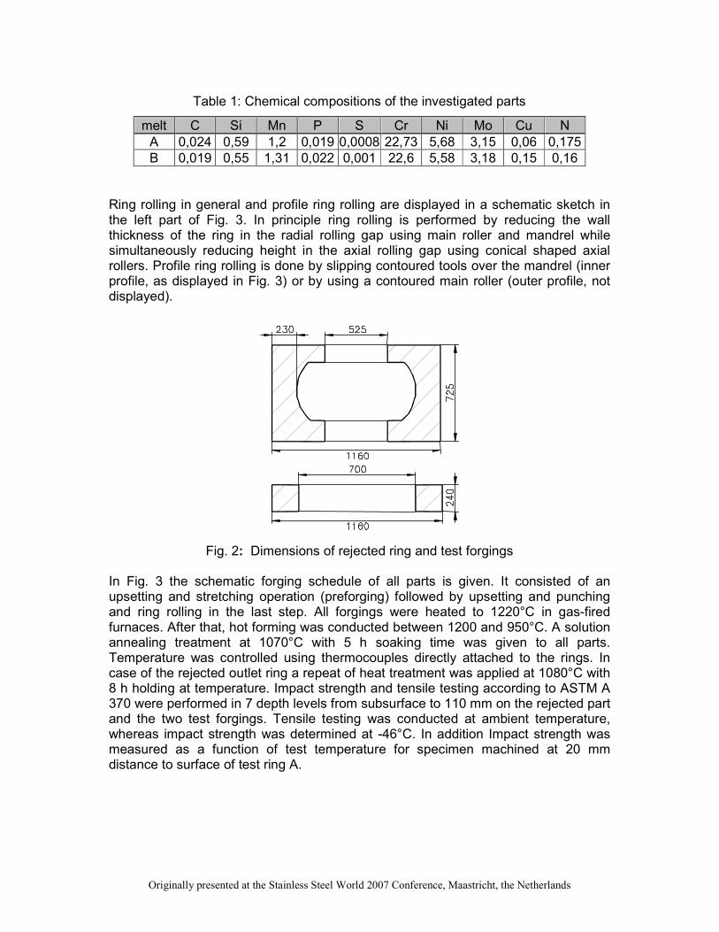
Before optimisation, the nature of parts that failed final acceptance testing was analysed. All affected parts were rejected due to low impact strength at the required test temperature and test locations. The impact strength testing for those parts was conducted at -40 to -50 °C and a minimum average/single value of 45/35 J was specified as often required in material data-sheets based on NORSOK standards. It should be mentioned that impact strength test temperature for DSS was -10°C about 20 years ago. In summary it was revealed that heavy parts with large wall thickness and low forging ratio are likely to fail during acceptance testing due to low impact strength. The properties and the microstructure of a rejected large wall thickness outlet ring were investigated as a function of test location from surface to centre. The rejected part had a profiled cross section given in Fig. 2, weighing 4500 kg in premachined condition. There was an attempt to solve the witnessed problems by several measures that were applied in the manufacturing of two test forgings. The two test rings had the same wall thickness as the rejected part, but differed in the square cross section as indicated in Fig. 2. The chemical composition of the two melts used for the production of the test rings is given in Table 1. They do not differ much from each other. Two different forging ratios have been realised using a preforged ingot (melt A) with 650 mm diameter (high forging ratio) and a cast ingot (melt B) with 500 mm diameter (intermediate forging ratio). The forging ratio of part A (melt A) was twice the forging ratio of part B (melt B).
Originally presented at the Stainless Steel World 2007 Conference, Maastricht, the Netherlands
Table 1: Chemical compositions of the investigated parts
melt C Si Mn P S Cr Ni Mo Cu N
A 0,024 0,59 1,2 0,019 0,0008 22,73 5,68 3,15 0,06 0,175
B 0,019 0,55 1,31 0,022 0,001 22,6 5,58 3,18 0,15 0,16
Ring rolling in general and profile ring rolling are displayed in a schematic sketch in the left part of Fig. 3. In principle ring rolling is performed by reducing the wall thickness of the ring in the radial rolling gap using main roller and mandrel while simultaneously reducing height in the axial rolling gap using conical shaped axial rollers. Profile ring rolling is done by slipping contoured tools over the mandrel (inner profile, as displayed in Fig. 3) or by using a contoured main roller (outer profile, not displayed).
Fig. 2: Dimensions of rejected ring and test forgings
In Fig. 3 the schematic forging schedule of all parts is given. It consisted of an upsetting and stretching operation (preforging) followed by upsetting and punching and ring rolling in the last step. All forgings were heated to 1220°C in gas-fired furnaces. After that, hot forming was conducted between 1200 and 950°C. A solution annealing treatment at 1070°C with 5 h soaking time was given to all parts. Temperature was controlled using thermocouples directly attached to the rings. In case of the rejected outlet ring a repeat of heat treatment was applied at 1080°C with 8 h holding at temperature. Impact strength and tensile testing according to ASTM A 370 were performed in 7 depth levels from subsurface to 110 mm on the rejected part and the two test forgings. Tensile testing was conducted at ambient temperature, whereas impact strength was determined at -46°C. In addition Impact strength was measured as a function of test temperature for specimen machined at 20 mm distance to surface of test ring A.

Originally presented at the Stainless Steel World 2007 Conference, Maastricht, the Netherlands
Fig. 3: Schematic sketch of ring rolling process (left upper part) and profile ring rolling (left lower part) and schematic sketch of forging process (right part)
Additionally two simulation heat treatments were accomplished and also evaluated by means of impact strength testing. First 15 mm thick plates were machined from the rejected part at different distances to surface. These plates were given a solution annealing at 1070°C/30 min. This was to determine the influence of wall thickness (i.e. cooling rate) on toughness. Secondly 15 mm thick specimens machined from part A at a distance of 15 mm to surface were subjected to artificial ageing at 475°C. Thus the influence of 475°C-embrittlement on impact strength and corrosion resistance could be evaluated. The microstructure of the parts was also investigated as a function of distance to surface. This was done by means of Optical Microscopy using Murakami´s Reagent which darkens ferrite and leaves the austenite nearly unaffected and bright. In cases imperfections were revealed, Scanning Electron Microscopy measurements were performed additionally. In two cases a Focused Ion Beam (FIB) device attached to the SEM was used to micromachine thin foils perpendicular to the specimen’s surface at suspicious sites. These foils were investigated in Transmission Electron Microscope. Corrosion resistance was determined according to ASTM G 48 method E [9] measuring Critical Pitting Temperature (CPT). Therefore specimens were subjected to a ferric chloride test solution for 24 h at different temperatures with steps of 5°C each. After this specimens were investigated by means of mass loss and by identification of pittings via low-magnification microscopy. CPT is the temperature with a mass loss greater than 4 g/m2 and/or the occurrence of pittings in low magnification microscopy.

Originally presented at the Stainless Steel World 2007 Conference, Maastricht, the Netherlands
3. Experimental Results and Discussion
3.1. Mechanical Properties
3.1.1. Rejected Outlet Ring The tensile test characteristics yield strength (Rp0,2), ultimate tensile strength (Rm), elongation at fracture (A5) and reduction of area (Z) for the rejected ring are given in Fig. 4. The typical requirements for F51 DSS were met in all test locations. Obviously, distance to surface has little influence on tensile properties. The slightly increased strength in the outermost test locations can be attributed to a higher degree of hot working near the surface in contrast to a lower degree in the core region. This phenomenon is often observed in DSS [4].
0
100
200
300
400
500
600
700
800
0 20 40 60 80 100 120
Distance to surface [mm]
Tensio
n [M
Pa]
0
10
20
30
40
50
60
70
80
90
100
Elo
ngation [%
]
Rp0,2
Rm
A5Z
Fig. 4: Tensile Properties of rejected part as a function of distance to surface
Impact strength in tangential and radial direction was measured at -46°C as a function of distance to surface. However, in almost all specifications only tangential testing is required. The impact strength of the rejected part is given as a function of distance to surface in Fig. 5. The chart shows a pronounced dependency of impact strength on distance to surface. As can clearly be seen, the minimum average value of 45 J in tangential direction is only surpassed in the outermost test location; all other values were below this limit. Therefore this part was rejected in final acceptance testing. After a repeat of heat treatment at 1080°C with 8 h time at temperature no improvement could be observed and the values barely changed. On the contrary, the impact strength values of the repeatedly solution annealed 15 mm thick plates machined from the rejected part (10, 45 and 110 mm distance to surface) were found to be between 100 and 240 J. This is well above the requirements and the values obtained from the original ring in all test locations. Thus one could conclude that the solution annealing temperature of 1070°C to 1080°C was

Originally presented at the Stainless Steel World 2007 Conference, Maastricht, the Netherlands
not sufficient to dissolve all particles possibly precipitated. During quenching of the whole rejected outlet ring the low cooling rates due to heavy weight and large wall thickness resulted in a re-precipitation with the undissolved particles acting as starters. In the thin plates this re-precipitation could have been suppressed by much higher cooling rates.
0,0
10,0
20,0
30,0
40,0
50,0
60,0
70,0
80,0
90,0
100,0
0 20 40 60 80 100 120
Distance [mm]
Impact str
ength
[J]
1070°C/5h + 1080°C/8h tangential
1070°C/5h/water + 1080°C/8h/water radial
minimum average value (NORSOK)
1070°C/5h/water tangential
1070°C/5h/water radial
Fig. 5: Impact strength at -46°C as a function of distance to surface – rejected part
3.1.2. Test Forgings A and B The tensile properties of the two test forgings A and B were again nearly independent on test location. As all requirements were met, their delineation is set aside. The impact strength values for test ring A and B are depicted in Fig. 6. Both rings show high values at -46°C and a strong dependency on distance to surface. Part A has an impact strength greater than 300 J for test locations between 10 and 25 mm from the surface. Then a sharp drop to values between 100 and 150 J can be observed. However, with values between 50 and 120 J the stringent NORSOK requirements would have comfortably been met. Part A would have passed a NORSOK qualification for parts with a wall thickness of 240 mm. On the other hand, part B featuring the lower forging ratio reveals a significantly lower impact strength compared to part A. As the overall forging ratio differs much between the two test forgings and because differences in chemical composition are only marginal, it can be assumed that the overall forging ratio has a pronounced effect on low temperature toughness.

Originally presented at the Stainless Steel World 2007 Conference, Maastricht, the Netherlands
0,0
50,0
100,0
150,0
200,0
250,0
300,0
350,0
0 20 40 60 80 100 120
Distance [mm]
Impact str
ength
[J]
melt B tangential
melt B radial
melt A tangential
melt A radial
min. value [NORSOK]
Fig. 6: Impact strength at - 46°C as a function of distance to surface – test forgings A
and B Impact strength versus temperature is depicted for specimens from test ring A at 20 mm distance to surface Fig. 7. High impact strength values from 200-300J could be obtained down to a temperature of -70 °C in this test location. At -80°C values between 100 and 150J were witnessed. On the base of NORSOK requirements, impact strength tests would have been passed down to -100°C.
0
50
100
150
200
250
300
-150 -140 -130 -120 -110 -100 -90 -80 -70 -60 -50 -40
Temperature [°C]
Impact str
ength
[J]
Sta
nd
ard
Test
Te
mpe
ratu
re R
ang
e (
NO
RS
OK
)
min. value (NORSOK)
Fig. 7: Impact strength versus test temperature (test ring A, 20 mm distance to
surface) A set of 15 mm thick plates machined from the surface of test ring A was subjected to an artificial ageing treatment at 475°C to provoke the ferrite decomposition. These

Originally presented at the Stainless Steel World 2007 Conference, Maastricht, the Netherlands
plates initially had an impact strength of more than 300 J. As can be concluded from Fig. 8 the impact strength is affected after less than 1 h of ageing. After 1,5 h the initial value is reduced to one half, after 2 h to one third. After a treatment of 36 h only 15 J are left. Thus the 475°C-embrittlement is likely to influence the impact strength of very large forgings.
0
50
100
150
200
250
300
0 200 400 600 800 1000 1200 1400
Time [min]
Impact str
ength
[J]
min. value (NORSOK)
Fig. 8: Impact strength at -46°C as a function of holding time at 475°C
3.2. Microstructural Investigation The low impact strength of the rejected outlet ring is assumed to result from the precipitation of detrimental phases. To evaluate this, the microstructures at the respective test locations had to be investigated. The microstructure of a specimen machined at a test location of 10 mm from surface is shown in the left side of Fig. 9. Precipitates on the ferrite grain boundaries can be observed (indicated by arrows). The right image in Fig. 9 exhibits the microstructure at a test location of 110 mm distance to surface. Besides the precipitates visible on the ferrite grain boundaries there are first stages of precipitation visible on the ferrite austenite phase boundaries (indicated by arrows). These precipitations on the phase boundaries are only visible in regions far from surface. The nature of the observed precipitates was investigated using SEM and TEM. The FIB attached to the SEM was applied to the TEM foil preparation at the respective boundary as indicated by the white bar in Fig. 10. The ferrite/austenite phase boundary in the SEM-image (left image) and the respective TEM-micrograph (right image) perpendicular to the phase boundary and surface are displayed in Fig. 10. The precipitation has a coral-like character in SEM. In the TEM image the precipitates are triangular in shape and obviously growing into the ferrite. The particles are arranged in an almost uninterrupted continuous layer. Note the high magnification of the TEM-image. As the particles are very small in size (< 100 nm) a

Originally presented at the Stainless Steel World 2007 Conference, Maastricht, the Netherlands
Selected Area Diffraction Pattern (SADP) of sufficient quality could not be obtained. However, Energy Dispersive X-Ray (EDX) analysis revealed high Cr and Mo contents in the precipitates, whereas Fe was depleted in respect to the matrix, but well present in the particles. The EDX findings as well as the phase morphology and the precipitation sites indicate that the particles found are likely to be σ-phase or one of its precursors [3,5].
Fig. 9: Microstructure at 10 and 110 mm distance to surface – rejected part
(Murakami’s Reagent, 1000x) The precipitates at the ferrite grain boundaries were investigated in the same manner. The TEM micrograph of such a boundary is shown in Fig. 11. Two precipitates can be observed. In this case a SADP of sufficient quality could be obtained due to the slightly larger diameter of the precipitates. The SADP illustrated on the right side of Fig. 11 unambiguously proves the particles to be Cr2N with selected zone axis [1-10]. EDX measurements revealed high Cr and moderate Mo contents whereas Fe was nearly totally depleted.
Fig. 10: SEM image (SE, 25000x; left) of ferrite/austenite phase boundary and bright
field TEM micrograph of ferrite/austenite phase boundary with precipitates (right)
Austenite
Ferrite
Austenite
Ferrite

Originally presented at the Stainless Steel World 2007 Conference, Maastricht, the Netherlands
Fig. 11: TEM micrograph and corresponding SADP of Cr2N precipitates (zone axis [1-10]) at ferrite grain boundary
As a first conclusion one could state that impact strength in the rejected part was found to be low due to the precipitation of Cr2N at ferrite grain boundaries all over the wall thickness of the part. In addition in regions far from surface the precipitation of σ-phase or one of its precursors can be observed. The tensile properties of the rejected outlet ring were not affected by these phenomena. The microstructures of the two optimised test forgings were essentially free from any precipitates, even in the core region. Nevertheless, Part A revealed much higher impact strength compared to part B. This can be explained comparing the microstructure of both parts at low magnification (Fig. 12, 50x). The high overall forging ratio of part A resulted in a fine microstructure, providing high inherent impact strength. On the other hand the lower forging ratio of part B produced a coarser microstructure with blocky austenite, resulting in lower impact strength.
Fig. 12: Typical Microstructure of Part A (left) and part B (right) (Murakami’s Reagent, 50x)
Ferrite
Ferrite

Originally presented at the Stainless Steel World 2007 Conference, Maastricht, the Netherlands
3.3. Corrosion Testing CPT tests according to ASTM G 48 test method E were conducted for specimens taken from the rejected outlet ring and test ring A. In addition, specimens machined from test ring A were artificially aged at 475°C and tested afterwards. All specimens were machined near to surface. The CPT results are displayed in Fig. 13.
0
5
10
15
20
25
30
20 30 40 50 60
Temperature [°C]
Weig
ht lo
ss [g/m
²]
rejected part 15 mm
test ring A 15 mm
test ring A 15 mm aged 475°C/36h
ASTM G 48 method E limit
Fig. 13: Weight loss as a function of test temperature in CPT-Test according ASTM
G 48 method E
The microstructure of the rejected part was affected by Cr2N-precipitates in the investigated test location and only 55 J of impact strength were measured at -46°C. Nevertheless a CPT-value of more than 30°C could be obtained, the first pittings were visible at 35°C. In contrast to this a CPT value of more than 55°C was measured for test forging A having 300 J impact strength and being free from any precipitates. If specimens machined at the same test location in test forging A were subjected to an artificial ageing at 475°C holding 36 h at temperature, a CPT of more than 40°C was determined, although the impact strength after ageing was only 15 J. CPT values between 30 and 40°C are reported in literature for ASTM G 48 method E tests [7]. Most specifications require a pitting test at 25°C under the same conditions (G48 method A). This means that even the rejected outlet ring affected by Cr2N precipitates (CPT > 30°C) was fit for purpose, as far as corrosion resistance is concerned. The CPT value measured for test forging A with the optimised process routine was 15 to 25 °C above the values reported in literature [7]. This means that an excellent corrosion resistance was obtained, also indicated by the very high impact strength and the precipitation-free microstructure. Even the CPT value of the artificially aged specimens is amongst the highest that have been reported to this date for F51 DSS.

Originally presented at the Stainless Steel World 2007 Conference, Maastricht, the Netherlands
In summary, one could state that by applying optimised forging and heat treatment processes excellent corrosion properties can be obtained. Nevertheless even parts affected by Cr2N-precipitation or 475°C-embrittlement can be fit for purpose as far as corrosion resistance is concerned. Therefore the precipitation reactions have much stronger influence on impact strength than on corrosion resistance.
4. Summary and Conclusions The internal statistical analysis of A 182 F51 DSS parts that were rejected in final acceptance testing revealed that all these parts were heavy in weight and had large wall thicknesses. At the same time the demand for those parts is increasing in offshore industry. Therefore the optimisation of forging and heat treatment processes was aimed at providing large wall thickness and heavy weight parts of high quality. As a first step the mechanical properties of a rejected outlet ring were investigated and correlated to microstructural features. Both, tensile properties and impact strength, were evaluated as a function of distance to surface. Ultimate tensile strength, yield strength, elongation at fracture and reduction of area were found to be well above the required values and were almost independent on test location. In contrary, impact strength at -46°C showed a pronounced dependency on distance to surface, only surpassing the minimum value of 45 J (NORSOK) in the outermost test location. The microstructural features of specimens machined at different distances to surface were investigated. The precipitation of Cr2N on ferrite grain boundaries was found all over the wall thickness of the rejected outlet ring, whereas the σ-phase at austenite/ferrite phase boundaries was only found in test locations more distant to surface as could be anticipated from time-temperature-transition diagrams for 2205-DSS [1]. Thus the low impact strength values could at least in part be attributed to precipitation reactions in the large wall thickness outlet ring. An additional heat treatment could not alter the impact strength properties and was thus not sufficient to dissolve all detrimental particles or inhibit their re-precipitation. Two test rings A and B were forged applying optimised forging and heat treatment processes. The usage of preforged material for part A resulted in a very high forging ratio. Impact strength was again measured as a function of distance to surface and much higher values were obtained. However, the values obtained for part A were twice as high as those of part B. This could be explained in terms of microstructural comparison, whereupon it emerged that part A had a much finer microstructure due to its higher overall forging ratio. Even in the core region of both test rings no precipitates were found, i.e. the wall thickness limit beyond which a precipitation free microstructure can not be obtained was not reached in this investigation. Therefore Part A would have passed the stringent NORSOK qualification for 240 mm wall thickness. The corrosion resistance of different microstructures was compared using ASTM G 48 method E CPT-tests. It revealed that all parts, even the rejected outlet ring, were fit for purpose from this point of view. However the corrosion resistance of part A with the optimised process routine proved to be excellent having a CPT of 55°C, i.e. 15 to 20°C higher than any ASTM G 48 CPT value reported in literature. Even after artificial ageing at 475°C, resulting in an impact strength of 15 J, a CPT of more than

Originally presented at the Stainless Steel World 2007 Conference, Maastricht, the Netherlands
40°C was measured indicating the excellent corrosion resistance as a result of the optimised process routine. As a conclusion the following statements can be given:
- Impact strength of large wall thickness parts can be affected by precipitation of Cr2N on ferrite grain boundaries and σ-phase at ferrite/austenite phase boundaries
- In addition the overall forging ratio has a vital influence on inherent impact strength of large wall thickness parts due to microstructural refinement
- Parts having low impact strength due to precipitation of Cr2N or 475°C embrittlement may nevertheless provide sufficient corrosion resistance (ASTM G 48 test)
- Forging temperature should be restricted to be above 1000°C to avoid any precipitation reactions during forging
- A repeat of solution annealing treatment of parts with low impact strength is not sufficient to prevent a re-precipitation
- The heat treatment conditions are critical: quench facilities should be as effective as possible to ensure high cooling rates; handling times between furnace and quench tank should be short; parts have to be premachined close to final dimensions before heat treatment
- Profile ring rolling is an appropriate measure to reduce wall thickness - If high forging ratios and strict temperature control are guaranteed,
precipitation-free and fine microstructures with very high low-temperature impact strength and excellent corrosion resistance can be achieved even in the core regions of DSS forgings and rings with large wall thicknesses
- For parts having very large wall thicknesses, precipitation of detrimental phases is unavoidable due to physical limits and cladding of low carbon steel may be a technological and economical alternative

Originally presented at the Stainless Steel World 2007 Conference, Maastricht, the Netherlands
5. References 1) Henes, D.; Cordevener, R.; Larsen, S.: Manufacturing, Assembly and Testing of Swivel Systems for Oil and Gas Applications, in: Proc. Stainless Steel World, Maastricht (2005), KCI, Zutphen, The Netherlands, (2005), p. 380 2) Bruch, D.; Henes, D.; Leibenguth, P.; Holzapfel, Ch.: Mechanical Properties and Corrosion Resistance of Duplex Stainless Steel Forgings with Large Wall Thicknesses, in: Proceedings Duplex International 2007, Grado, 2007 3) Zucato, I.; Moreira, M. C.; Machado, I. F.; Lebraco S. M.: Microstructural Characterization and the Effect of Phase Transformations on Toughness of the UNS S31803 Duplex Stainless Steels Aged Treated at 850°C, in: Mat. Res. 5, (2002), p. 385 4) Roberti, R.; Faccoli, M.; Bondioni, B.; Veronesi, C.: Mechanical, corrosion and
microstructural properties of duplex stainless steel forging bars with ∅ > 400 mm, in: Proc. SSW DUPLEX America, Houston (2000), KCI, Zutphen, The Netherlands (2000), p. 157 5) Nilsson, J. O.: The physical metallurgy of duplex stainless steels, in: Proc. 5th World Conf. Duplex Stainless Steels, Maastricht (1997), KCI, Zutphen, The Netherlands (1997), p. 73
6) Havn, T.; Morini, A.; Salbu, H.; Strandmyr, ∅.: Quality improvements on duplex and superduplex cast and forged products for offshore applications: producer and user viewpoints, in: Proc. 5th World Conf. Duplex Stainless Steels, Maastricht (1997), KCI, Zutphen, The Netherlands (1997), p. 191 7) Lardon, J. M.; Cozar, R.: Heavy section duplex and superduplex stainless steels forgings for use in the oil and gas industry, in: Proc. 5th World Conf. Duplex Stainless Steels, Maastricht (1997), KCI, Zutphen, The Netherlands (1997), p. 147 8) Weng, K. L.; Chen, T. H.; Yang, J. R.: The high-temperature and low-temperature aging embrittlement in a 2205 duplex stainless steel, in: Bulletin of the College of Engineering, N.T.U. 89, (2003), p. 45 9) ASTM G 48 – 03, ASTM Book of Standards 03.02, ASTM International, West Conshohocken, Pennsylvania (2003)


