
Investigation of Underwater Wireless Optical Communication ...
7
W ireless data communication in the underwater environment started with the measurement of the sound velocity underwater in 1826. After that, it gained a strong acceleration with the submarine technology developed during the 1st and 2nd World Wars [1]. Today, high-speed real-time underwater wireless data communication is in huge demand in many commercial and military applications such as ocean exploration, offshore oil industry, remote cont- rolled unmanned underwater vehicles, port security and control [2,3]. In underwater environment, data can be transmit- ted wirelessly by three types of waves: electromagnetic, acoustic and optical [4]. Since the electromagnetic wa- ves attenuate rapidly in the underwater environment, the data communication distance and speed can be ac- hieved at 10 m and Mbps levels, respectively [4,5]. Low frequencies are used in these systems because electro- magnetic waves are attenuated less at lower frequenci- Article History: Received: 2020/05/16 Hittite Journal of Science and Engineering, 2020, 7 (4) 279– 285 ISSN NUMBER: 2148–4171 DOI: 10.17350/HJSE19030000197 Investigation of Underwater Wireless Optical Communication Channel Capacity for Different Environment and System Parameters Yigit Mahmutoglu 1 Cenk Albayrak 2 Kadir Turk 3 1 Recep Tayyip Erdogan University, Department of Electrical and Electronics Engineering, Rize, Turkey 2 Karadeniz Technical University, Department of Energy Systems Engineering, Trabzon, Turkey 3 Karadeniz Technical University, Department of Electrical-Electronics Engineering, Trabzon, Turkey Accepted: 2020/09/28 Online: 2020/12/31 Correspondence to: Yigit Mahmutoglu, Deparment of Electrical and Electronics Engineering, Recep Tayyip Erdogan University, Rize, Turkey Tel: +90 4642237518 Fax: +90 4642237514 E-Mail:yigit.mahmutoglu@erdogan. edu.tr es in the underwater environment. For this reason, the antenna lengths of the mentioned systems are getting larger. Moreover, high-power transmitters are needed for these systems [5]. Another alternative for wireless communication in underwater is acoustic communication systems [5]. It is possible to transmit data to kilometers away using acoustic waves. However, since the bandwidth of acous- tic waves, that can be used for communication at these distances is quite narrow, data transmission can only be achieved at kbps levels [4]. Acoustic systems are costly because they need high power transmitters [5]. In addi- tion, these systems cause high delay and have negative effects on marine life [6]. On the other hand, using the optical waves in the blue / green bands of the visible light spectrum, data transmission at Gbps data rate levels can be achieved at distances between 10 and 100 m [3,5]. In [7], using ABSTRACT U nderwater wireless optical communication (UWOC) systems using the blue / green bands of the visible light spectrum stand out as an important solution in underwater ap- plications that require high data communication rate such as remote sensing and navigation, real-time video transmission and imaging. The main factor that limits the data communica- tion distance and determines the data rate in UWOC systems is the disruptive (absorption and scattering) effects of the underwater environment on optical waves. In this study, the signal to noise ratio (SNR) and channel capacity for UWOC systems are presented according to the divergence angle of the beam and the change in the aperture diameter of the receiver, which are the important parameters for UWOC systems. These examinations were repeated for pure sea water, clean ocean water, coastal ocean water and harbor water environments commonly used in the literature, and the obtained results were compared. With the present- ed results, the current limits for UWOC systems have been revealed and provide predictions about the applications that can be realized with UWOC systems for different environments.. INTRODUCTION Keywords: Underwater wireless optical communication, Channel capacity, Underwater wireless optical channel, Underwater optical noise, Underwater environments
Transcript of Investigation of Underwater Wireless Optical Communication ...

Wireless data communication in the underwater environment started with the measurement
of the sound velocity underwater in 1826. After that, it gained a strong acceleration with the submarine technology developed during the 1st and 2nd World Wars [1]. Today, high-speed real-time underwater wireless data communication is in huge demand in many commercial and military applications such as ocean exploration, offshore oil industry, remote cont-rolled unmanned underwater vehicles, port security and control [2,3].
In underwater environment, data can be transmit-ted wirelessly by three types of waves: electromagnetic, acoustic and optical [4]. Since the electromagnetic wa-ves attenuate rapidly in the underwater environment, the data communication distance and speed can be ac-hieved at 10 m and Mbps levels, respectively [4,5]. Low frequencies are used in these systems because electro-magnetic waves are attenuated less at lower frequenci-
Article History: Received: 2020/05/16
Hittite Journal of Science and Engineering, 2020, 7 (4) 279–285
ISSN NUMBER: 2148–4171
DOI: 10.17350/HJSE19030000197
Investigation of Underwater Wireless Optical Communication Channel Capacity for Different Environment and System Parameters Yigit Mahmutoglu1 Cenk Albayrak2 Kadir Turk3
1Recep Tayyip Erdogan University, Department of Electrical and Electronics Engineering, Rize, Turkey 2Karadeniz Technical University, Department of Energy Systems Engineering, Trabzon, Turkey3Karadeniz Technical University, Department of Electrical-Electronics Engineering, Trabzon, Turkey
Accepted: 2020/09/28Online: 2020/12/31
Correspondence to: Yigit Mahmutoglu, Deparment of Electrical and Electronics Engineering, Recep Tayyip Erdogan University, Rize, TurkeyTel: +90 4642237518Fax: +90 4642237514E-Mail:yigit.mahmutoglu@erdogan. edu.tr
es in the underwater environment. For this reason, the antenna lengths of the mentioned systems are getting larger. Moreover, high-power transmitters are needed for these systems [5].
Another alternative for wireless communication in underwater is acoustic communication systems [5]. It is possible to transmit data to kilometers away using acoustic waves. However, since the bandwidth of acous-tic waves, that can be used for communication at these distances is quite narrow, data transmission can only be achieved at kbps levels [4]. Acoustic systems are costly because they need high power transmitters [5]. In addi-tion, these systems cause high delay and have negative effects on marine life [6].
On the other hand, using the optical waves in the blue / green bands of the visible light spectrum, data transmission at Gbps data rate levels can be achieved at distances between 10 and 100 m [3,5]. In [7], using
A B S T R A C T
Underwater wireless optical communication (UWOC) systems using the blue / greenbands of the visible light spectrum stand out as an important solution in underwater ap-
plications that require high data communication rate such as remote sensing and navigation, real-time video transmission and imaging. The main factor that limits the data communica-tion distance and determines the data rate in UWOC systems is the disruptive (absorption and scattering) effects of the underwater environment on optical waves. In this study, the signal to noise ratio (SNR) and channel capacity for UWOC systems are presented according to the divergence angle of the beam and the change in the aperture diameter of the receiver, which are the important parameters for UWOC systems. These examinations were repeated for pure sea water, clean ocean water, coastal ocean water and harbor water environments commonly used in the literature, and the obtained results were compared. With the present-ed results, the current limits for UWOC systems have been revealed and provide predictions about the applications that can be realized with UWOC systems for different environments..
INTRODUCTION
Keywords: Underwater wireless optical communication, Channel capacity, Underwater wireless optical channel, Underwater optical noise, Underwater environments
Y. M
ahm
utog
lu e
t al./
Hitt
ite J
Sci E
ng, 2
020,
7 (4
) 279
–285
280
investigated. With the presented results, the available limits for UWOC systems have been revealed and it is hoped that readers can be given an idea about the applications that can be realized with UWOC systems for various environments.
ANALYSIS METHODIn this study, first of all, underwater wireless optical com-munication channel for UWOC systems and the noise in this channel are introduced in section 2.1. and section 2.2., respectively. The method followed in the rest of the investigation is as follows. The power of the signal rece-ived from the transmitter at the receiver side, the signal to noise ratio (SNR) and the resulting channel capacity are examined. Received signal power and channel capa-city are presented according to the variation in the di-vergence angle of the beam and the aperture diameter of the receiver which are important parameters for UWOC transmitter and receiver units. In addition, these exami-nations were repeated for pure sea water (PSW), clean ocean water (COW), coastal ocean water (CAOW) and harbor water (HW) environments, which are commonly considered in the literature, and the obtained results were compared.
UNDERWATER WIRELESS OPTICAL COMMUNICATION CHANNEL
In optical wireless communication systems, the most common link used in point to point communicati-on is line of sight (LOS) link. LOS scenario discussed in this study is shown in Fig. 1. In this scenario, the trans-mitter is assumed to direct the light towards the receiver. The Eq. (1) states the power of the optical signal received by the receiver [17].
( )20
cos,cos 2 1- cos
alal ve al ve yk
d AP P Ld
θη η λθ π θ
=
(1)
Here, alη and veη are optical efficiencies of receiver
and transmitter, alA is the aperture area of the receiver,
veP is the average optical power of the transmitter,
,cosyk
dL λθ
is propagation loss factor, λ is wavelength of
the light, d is the vertical distance between the receiver and the transmitter planes, θ is the angle between the transmitter-receiver projection and the perpendicular to the receiver plane and θ0 is divergence angle of the beam.
Due to its coaction with dissolved particles and water molecules in water, light is subject to a certain absorption and scattering depending on wavelength and distance [18]. These effects are expressed by the propagation loss factor given in the Eq. (2).
a laser source with 15 mW power, a data transmission of 12.4 Gbps up to 6 m was achieved. In [8], using a laser sour-ce with a power of 2000-3000 mW, data rate ranging from Mbps to Gbps up to 80 was achieved. In [9], data communi-cation was provided at a speed of 5 Gbps up to 64 m using a LED source with 3000 mW power. In [10], using a LED source with a power of 1000 mW, data transmission spe-eds of 1 Gbps up to 30-50 m distance were achieved. In [11], data transmission was provided at a speed of 1 Gbps up to 31 m distance by using a 100 mW LED source. Compared to electromagnetic and acoustic systems, in the underwater environment, UWOC systems are the only alternative for applications requiring high-speed data communication at short and medium range. In addition, UWOC systems need much lower transmit power to allow data communication in underwater environment.
In the field of wireless underwater communicati-on, where interest has increased in recent years, UWOC systems attract the attention of technological and acade-mic communities as a very important alternative due to the above mentioned features. Data transmission distance, data rate, reliability of transmission and similar features of UWOC systems are limited due to the disruptive (absorp-tion and scattering) effects of the underwater environment on optical waves. In practice, it is important to identify ef-fects of the underwater wireless optical channel in detail in order to determine the usage scenarios of UWOC systems and to design systems. In [12], where the Beer-Lambert channel model is employed, the effects of refractive index of the water and communication distance on SNR for four dif-ferent water types have been examined. In [13], three diffe-rent water types are considered and the performance of the UWOC system has been examined for various attenuation coefficients, where Monte Carlo channel model is used. In [14], channel capacity equations are derived for three situa-tions depending on the ratio between the allowed average power and the allowed peak power based on the Beer-Lam-bert channel model. An examination has been given on the variation of the channel capacity according to the relevant conditions and three different water types. In [15] and [16], the performance of the UWOC system with impacts of air bubbles in the underwater environment and turbulence were examined, respectively. The studies outlined above do not fully provide the performance limits of a typical UWOC system. In this study, we have demonstrated the capacity li-mits that can be reached by distance in various underwater environments in case of changing important design para-meters of the system such as the beam divergence angle and the aperture diameter of the receiver.
In this study, the variation of received powers and channel capacity for a typical UWOC system according to some basic system parameters and different water types was

281
Y. M
ahm
utog
lu e
t al./
Hitt
ite J
Sci E
ng, 2
020,
7 (4
) 279
–285
( ), exp -cos cosyk
d dL Kλ λθ θ
= (2)
Here, K(λ), which can be calculated as in the Eq. (3), is the attenuation coefficient.
( ) ( ) ( )K λ α λ β λ= + (3)
Here, α(λ) represents absorption coefficient and β(λ) stands for scattering coefficient. Absorption and scatte-ring coefficients are two important factors that define light attenuation in the underwater environment. In ab-sorption process, which is known as an energy transfer process, photons lose their energy and this energy turns into a different form: heat or chemical (photosynthesis). Scattering occurs when light interacts with the water mo-lecules and atoms. While absorption causes the light to attenuate and the data communication distance to limit in a UWOC system, scattering decreases the amount of photons reaching the receivers and the SNR of the rece-ived signal [18]. Typical values of α(λ), β(λ) and K(λ) are given in the literature as in Table 1 for four types of water: PW, COW, CAOW and HW. Attenuation coefficient de-pends on many parameters such as temperature, pressu-re, density of chlorophyll, plankton, detritus, colored dis-solved organic materials and so on. Turbidity is effected by density of chlorophyll, plankton, detritus and colored dissolved organic materials [18]. Thus, the turbidity is di-rectly proportional to the attenuation coefficient. For this reason, we can list the water types as pure water, clear ocean water, coastal ocean water and harbor water from small to large according to their turbidity levels. These water types (accordingly turbidity) represent the typical performance results for the best and worst cases and ot-her cases between them for underwater wireless optical communication.
NOISEIn the UWOC system, there are many noise sources that affect the optical signals transmitted wirelessly through
the underwater environment, in the photo-detector of the receiving unit. These noise sources can be listed as thermal noise, ambient light background noise, shot noi-se and dark current noise [10,19]. In this study, similar to [20], for the ease of operation, the shot noise was neglec-ted and the total noise affecting the received signal by the photo-detector was composed of thermal, dark current and ambient light (solar) background noise components.
The main source of ambient light background noise is sunlight reflected from the surface of the water. The varian-ce of ambient light background noise is calculated as given in the Eq. (4). Here q is the electronic charge, S is the sensiti-vity of the photo-detector and B is the electrical bandwidth. Psol represents ambient light background noise power and is calculated as given in the Eq. (5).
2 2sol solqSP Bσ = (4)
( )22 2
4F sol
sol
D FOV T LP
π λ∆= (5)
Here, D is the aperture diameter of the photo-detec-tor, FOV is the field of view of the system in radians, ∆λ is the bandwidth of the optical filter and TF is the optical filter transmissivity. Lsol is upwelling solar radiance and is calcu-lated as given in the Eq. (6).
( )-Khfac
sol
ERL eL
π= (6)
Here, Lfac is the factor that describes the directional dependence of the underwater radiance, E is downwelling irradiance, K attenuation coefficient, R is underwater reflec-tance of the downwelling irradiance and h is depth of the receiver.
Dark current noise is caused by constant current that occurs when light does not fall on the photo-detector. The variance of this noise is given in the Eq. (7). Here, Ikar denotes the dark current value.
2 2kar karqI Bσ = (7)
Figure 1. LOS communication scenario.
Table 1.Typical values of α(λ), β(λ) and K(λ) for various water types [18].
Water types ( ) -1 ( )mα λ ( ) -1 ( )mβ λ ( ) -1 ( )K mλ
PW (Pure Sea Water) 0.053 0.003 0.056
COW (Clean Ocean Water) 0.114 0.037 0.151
CAOW (Coastal Ocean Water) 0.179 0.219 0.398
HW (Harbor Water) 0.295 1.875 2.170

Y. M
ahm
utog
lu e
t al./
Hitt
ite J
Sci E
ng, 2
020,
7 (4
) 279
–285
282
Thermal noise varies depending on resistance, tempe-rature and bandwidth, and the variance of thermal noise is calculated as given in the Eq. (8). Here k, RL,Te, and F are Boltzman constant, load resistance, temperature in Kelvin and noise figure of the system, respectively.
2 4
eter
L
kT FBR
σ = (8)
The variance of the total noise affecting the signal rece-ived in the photo-detector is obtained as given in the Eq. (9).
2 2 2 2top sol kar terσ σ σ σ= + + (9)
The channel capacity of a communication system is calculated as given in the Eq. (10) (the Shannon-Hartley the-orem) depending on the signal to noise ratio and bandwidth [21].
( )b 21R B log 1 SNR2
= + (10)
NUMERICAL RESULTS AND DISCUSSIONIn this section, the effects of aperture diameter of the receiver and beam divergence angle parameters on the UWOC system are examined for various underwater en-vironments. Depending on the parameters handled, vari-ations in the channel capacity and power of the signal at the receiver are given and interpreted. Channel capacity is derived as in Eq. (11) using Eq. (1), Eq. (9) and Eq. (10). In the conducted studies, PW, COW, CAOW and HW environments, which are widely used in the literature for comparison, have been taken into consideration. For these underwater environments, α(λ), β(λ) and K(λ) co-efficient values, which are given in Table1, are used. As given in Fig. 1, a scenario, where there is LOS link bet-ween the transmitter and receiver units (two underwater vehicles) and they communicate with each other via the UWOC system, is discussed. The parameter values for the UWOC system and the transmitter - receiver units are given in Table 2. In addition, it was assumed that the transmitter power is 1 Watt in all the studies.
( )2 2 20
, cos1 coslog 12 2 1- cos
ve al ve yk al
btop
dP L AR B
d
η η λ θθ
σ π θ
= +
(11)
For the mentioned water environments, the variations of the signal power at the receiver (photo-detector) accor-
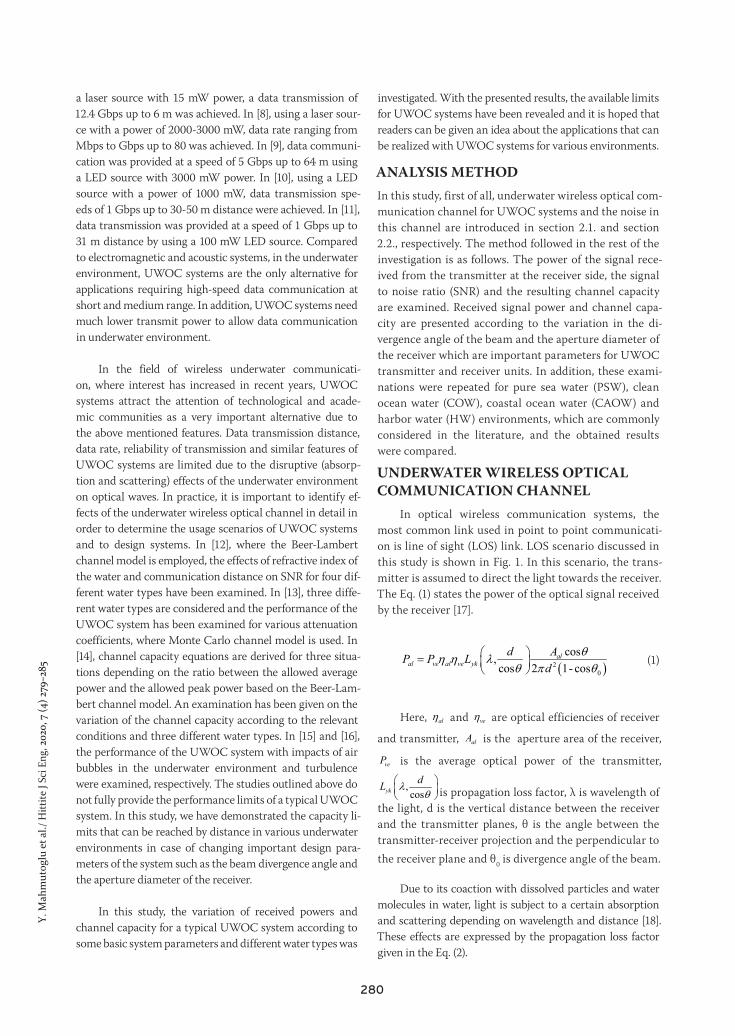
ding to the communication distance are given in Fig. 2. The-se results were obtained for the beam divergence angle of 5° and aperture diameter of the receiver of 50 cm. When the absorption and scattering coefficients for the underwa-ter environments, which are given in Table 1, are taken into consideration, it is seen that the dominance of the disruptive effects is increasing as PSW, COW, CAOW and HW, res-pectively. Therefore, as expected, the results in Fig. 2 showed that for the same transmitter power, in the PSW environ-ment data communication can be carried out at the longest distance, while in the HW environment, data communicati-on can be made at the shortest distance. In other words, the greater the distance and the turbidity cause more photons to scatter and the light becomes weaker, so power of the re-ceived signal decreases.
The relationships between power of the signal at the receiver and the beam divergence angle are given in Fig. 3.
Table 2.Parameter values of the mentioned UWOC system [10, 19, 22, 23].
Parameter Value
System parameters
Electrical bandwidth (B) 100 MHz
Aperture diameter of receiver (D) 1-50 cm
Beam divergence angle ( 0θ ) 0 01 - 30
Average transmitter optical power (Pve)
1 W
Depth of receiver (h) 30 m
Wavelength (λ) 532 nm
Angle between the perpendicular to the receiver plane and the
transmitter-receiver projection ( θ )00
Field of view (FOV) 040
Bandwidth of the optical filter (∆λ) 10 nm
Optical efficiency of the transmitter (ηve)
0.9
Optical efficiency of the receiver (ηal)
0.9
Sensitivity of the receiver (S) 0.35 A/W
Optical filter transmissivity (TF) 0.5
Load resistance (RL) 100 Ω
Noise figure of the system (F) 4
Dark current (Ikar) 1.226 nA
Ambiet parameters
Downwelling irradiance (E) 1440 W/m2
Underwater reflectance of the downwelling irradiance (R) % 1.25
Factor describing the directional dependence of the underwater
radiance (Lfac)2.9 (horizontally)
Temperature (Te) 290 K
ConstantsBoltzman constant (k) -231.38 10 /J K×
Electronic charge (q) -191.6 10 C×
283
Y. M
ahm
utog
lu e
t al./
Hitt
ite J
Sci E
ng, 2
020,
7 (4
) 279
–285
For these examinations, distance between the transmitter and receiver units is taken as 10 m and aperture diameter of the receiver is taken as 50 cm. Beam divergence angle is changed from 1° to 30°. It is seen that the power of the signal at the receiver decreases when the divergence angle increases. According to the dominance of the disruptive effects, the power levels of the received signals for various underwater environments are sorted as in Fig. 3. When the divergence angle is increased from 1° to 30°, the power of the signal decreases approximately 50 dB for each under-water environment. Increasing the divergence angle causes the optical beam to spread rather than focus on somewhere. In this case, the power of the optical signal coming to the receiver will be lower than the focused optical signal.
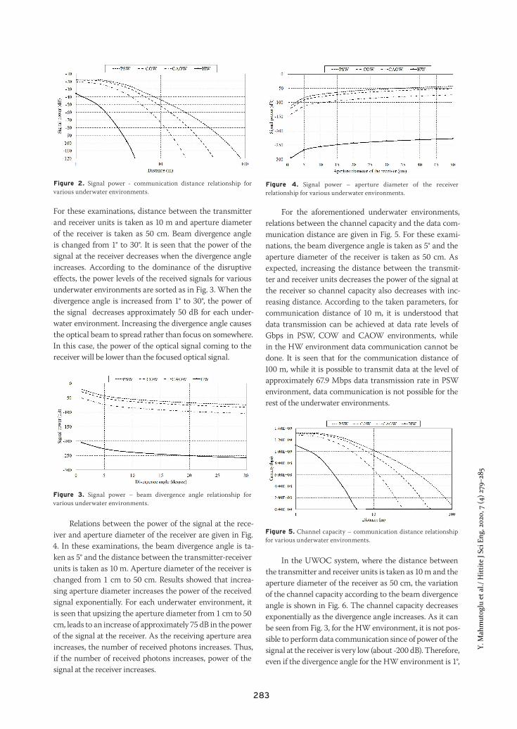
Relations between the power of the signal at the rece-iver and aperture diameter of the receiver are given in Fig. 4. In these examinations, the beam divergence angle is ta-ken as 5° and the distance between the transmitter-receiverunits is taken as 10 m. Aperture diameter of the receiver ischanged from 1 cm to 50 cm. Results showed that increa-sing aperture diameter increases the power of the receivedsignal exponentially. For each underwater environment, itis seen that upsizing the aperture diameter from 1 cm to 50 cm, leads to an increase of approximately 75 dB in the power of the signal at the receiver. As the receiving aperture areaincreases, the number of received photons increases. Thus,if the number of received photons increases, power of thesignal at the receiver increases.
For the aforementioned underwater environments, relations between the channel capacity and the data com-munication distance are given in Fig. 5. For these exami-nations, the beam divergence angle is taken as 5° and the aperture diameter of the receiver is taken as 50 cm. As expected, increasing the distance between the transmit-ter and receiver units decreases the power of the signal at the receiver so channel capacity also decreases with inc-reasing distance. According to the taken parameters, for communication distance of 10 m, it is understood that data transmission can be achieved at data rate levels of Gbps in PSW, COW and CAOW environments, while in the HW environment data communication cannot be done. It is seen that for the communication distance of 100 m, while it is possible to transmit data at the level of approximately 67.9 Mbps data transmission rate in PSW environment, data communication is not possible for the rest of the underwater environments.
In the UWOC system, where the distance between the transmitter and receiver units is taken as 10 m and the aperture diameter of the receiver as 50 cm, the variation of the channel capacity according to the beam divergence angle is shown in Fig. 6. The channel capacity decreases exponentially as the divergence angle increases. As it can be seen from Fig. 3, for the HW environment, it is not pos-sible to perform data communication since of power of the signal at the receiver is very low (about -200 dB). Therefore, even if the divergence angle for the HW environment is 1°,
Figure 3. Signal power – beam divergence angle relationship for various underwater environments.
Figure 5. Channel capacity – communication distance relationship for various underwater environments.
Figure 2. Signal power - communication distance relationship for various underwater environments.
Figure 4. Signal power – aperture diameter of the receiver relationship for various underwater environments.

Y. M
ahm
utog
lu e
t al./
Hitt
ite J
Sci E
ng, 2
020,
7 (4
) 279
–285
284
the channel capacity is quite close to zero level (about 2 bps). When the divergence angle is increased from 1° to 30°, data rates for PSW, COW and CAOW environments decreased by rate of %52.2, %48.3 and %34.5, respectively.
The variations of the channel capacity according to aperture diameter of the receiver are given in Fig. 7. In these examinations, the beam divergence angle is taken as 5° and the communication distance is taken as 10 m. It is seen that increasing the aperture diameter of the receiver increases the channel capacity exponentially. It is deduced that in the HW environment, in line with the system parameters con-sidered for these results, since the power of the signal at the receiver is too low (below -200 dB), it is not possible to per-form data communication at a distance of 10 m even if aper-ture diameter of the receiver increases. On the other hand, increasing aperture diameter of the receiver from 1 cm to 50 cm increases the data rates approximately 4 times and 6 times in PSW and COW environments, respectively. In the CAOW environment, it is only possible to perform data communication at 5.6 Mbps by using aperture diameter of 1 cm. However, it is possible to transmit data at 676 Mbps data rate level with aperture diameter of 50 cm. As the channelcapacity directly depends on power of the received signal,the reasons that cause obtained results are the same as inpower of the received signal results.
The obtained results showed that the performance of UWOC systems differs significantly for various environ-ment and system parameters. Therefore, it is clear that in
marine environments, where system parameters and envi-ronment can always change, systems must be designed to operate in a wide SNR range in order to achieve efficient communication. For this reason, it is seen that an adapti-ve modulation and coding (AMC) algorithm is needed in which the depth of the modulation used in communication and the rate of error correction codes are changed accor-ding to the changing SNR value. In addition, energy can be saved by changing the transmitter power according to the SNR value obtained in the receiver. In all results, the trans-mitter optical power was chosen as 1 W. For different trans-mitter powers, the results can be easily calculated and used for system designs. It is possible to increase the communica-tion distance and / or capacity by increasing the transmitter power.
CONCLUSIONIn this study, for underwater wireless communication systems the distribution of signal noise ratio and chan-nel capacity for various values of the beam divergen-ce angle and aperture diameter of the receiver in PSW, COW, CAOW and HW environments were examined. The obtained results, revealed that the performance of UWOC systems differs significantly for various environ-ments and system parameters. Therefore, it is clear that in underwater environments, where system parameters and the ambient can always change, systems must be de-signed to operate in a wide SNR range in order to com-municate effectively. In all of the numerical analyses, the transmitter optical power was chosen as 1 W. For diffe-rent transmitter powers, the results can be easily calcula-ted and used for system designs.
R E F E R E N C E S
1. Quazi AH, Konrad WL. Underwater acoustic communications.IEEE Communications Magazine 20 (1982) 24–30.
2. Miramirkhani F, Uysal M. Visible Light Communication Channel Modeling for Underwater Environments with Blocking andShadowing. IEEE Access 6 (2017) 1082-1090.
3. Chen H, Chen X, Lu J, Liu X, Shi J, Zheng L, Liu R, Zhou X.,Tian P. Toward Long-Distance Underwater Wireless OpticalCommunication Based on A High-Sensitivity Single PhotonAvalanche Diode. IEEE Photonics Journal 12 (2020) 7902510.
4. Shihada B, Amin O, Bainbridge C, Jardak S, Alkhazragi O,Ng TK, Ooi B, Berumen M, Alouini MS. Aqua-Fi: DeliveringInternet Underwater Using Wireless Optical Networks. IEEECommunications Magazine 58 (2020) 84-89.
5. Kaushal H, Kaddoum G. Underwater Optical WirelessCommunication. IEEE Access 4 (2016) 1518–1547.
6. Che X, Wells I, Dickers G, Kear P, Gong X. Re-Evaluation of RFElectromagnetic Communication in Underwater Sensor Networks. IEEE Communications Magazine 48 (2010) 143–151.
7. Wu TC, Chi YC, Wang HY. Blue laser diode enables underwatercommunication at 12.4Gbps. Scientific Reports 7 (2017) 1–10.
8. Miller JK, Morgan K, Li W, Li Y, Johnson, E. Data Agile Underwater Optical Communication Link using Flexible Data Formats and
Figure 6. Channel capacity – beam divergence angle relationship for various underwater environments.
Figure 7. Channel capacity – aperture diameter of the receiver relationship for various underwater environments.

285
Y. M
ahm
utog
lu e
t al./
Hitt
ite J
Sci E
ng, 2
020,
7 (4
) 279
–285
Orbital Angular Momentum Multiplexing. Paper presented at OCEANS 2018 MTS/IEEE, Charleston, SC, USA, 22-25 October, IEEE, pp. 1–4, 2018.
9. Cochenour B, Mullen L, Laux A. Spatial and temporal dispersionin high bandwidth underwater laser communication links. Paperpresented at IEEE Military Commununications Conference, SanDiego, CA, USA, 16-19 November, IEEE, pp. 1–7, 2008.
10. Jaruwatanadilok S. Underwater wireless optical communicationchannel modeling and performance evaluation using vectorradiative transfer theory. IEEE Journal on Selected Areas inCommunications 26 (2008) 1620–1627.
11. Gabriel C, Khalighi A, Bourennane S, Léon R, Rigaud V. Opticalcommunication system for an underwater wireless sensor network. Paper presented at EGU General Assembly, Vienna, Austria, 22-27 April, pp. 2685, 2012.
12. Ali M. Characteristics of Optical Channel for Underwater OpticalWireless Communication System. IOSR Journal of Electrical andElectronics Engineering 10 (2015) 1-9.
13. .Li J, Ma Y, Zhou Q, Wang H. Channel capacity study of underwater wireless optical communications links based on Monte Carlosimulation. Journal Of Optics A: Pure And Applied Optics 14 (2012) 015403.
14. Matta G, Agrawal M, Bahl R. Channel Capacity for UnderwaterVisible Light Communication Systems. Paper presented at Oceans 2019, Marseille, France, 17-20 June, IEEE, pp. 1-4, 2019.
15. Shin M, Park K, Alouini M. Statistical Modeling of the Impact ofUnderwater Bubbles on an Optical Wireless Channel. IEEE OpenJournal of the Communications Society 1(2020) 808-818.
16. Zhang S, Zhang L, Wang Z, Quan J, Cheng J, Dong Y. OnPerformance of Underwater Wireless Optical CommunicationsUnder Turbulence, Paper presented at IEEE 17th Annual Consumer Communications & Networking Conference (CCNC), Las Vegas,NV, USA, 10-13 January, IEEE, pp. 1-2, 2020.
17. Arnon S. Underwater optical wireless communication network.Optical Engineering 49 (2010) 015001-1–015001-6.
18. Zeng Z, Fu S, Zhang H, Dong Y, Cheng J. A Survey of Underwater Optical Wireless Communications. IEEE CommunicationsSurveys & Tutorials 19 (2017) 204–238.
19. Giles JW, Bankman IN. Underwater optical communicationssystems. Part 2: basic design considerations. Paper presented atIEEE Military Communications Conference, Atlantic City, NJ,USA, 17-20 October, IEEE, pp. 1–6, 2005.
20. Zhang H, Dong Y, Hui L. On Capacity of Downlink UnderwaterWireless Optical MIMO Systems With Random Sea Surface. IEEE Communications Letters 19 (2015) 2166–2169.
21. Sticklus J, Hoeher PA, Röttgers, R. Optical UnderwaterCommunication: The Potential of Using Converted Green LEDsin Coastal Waters. IEEE Journal Of Oceanic Engineering 44 (2019) 535–547.
22. Manor H, Arnon S. Performance of an optical wirelesscommunication system as a function of wavelength. Applied Optics 42 (2003) 4285–4294.
23. Boucouvalas AC. Underwater Optical Wireless CommunicationsWith Optical Amplification and Spatial Diversity. IEEE Photonics Technology Letters 28 (2016) 2613–2616.


