Investigation of the Heave Dynamics of Air Cushion Vehicles … · · 2013-04-16A. S. Sowayan et...
21
10(2013) 725 – 745 Abstract A highly non-linear model for the dynamics behavior of Air Cush- ion Vehicles (ACV) is presented. In this model the compressible Bernoulli's equation, the Newton's second law of motion, and the nonlinear isentropic relations are used to predict the dynamics behavior of only the vertical response of the ACV in both time and frequency domains. In this paper the mass flow rate inside the air cushion volume of the ACV is maintained constant. In order to assist in the design process of such vehicles, the self excited re- sponse and the cushion pressure of the ACV are calculated to understand the dynamic behavior of these vehicles. It is shown in this study that the mass flow rate and the length of the vehicle's skirt are the most significant parameters which control the steady state behavior of the self excited oscillations of the ACV. An equation to predict the transient time of the oscillatory response or the settling time in terms of the system parameters is devel- oped. Based on the developed equations, the optimum parameters of the ACV that lead to minimum settling time are obtained. Also, the chaotic behavior of the heave dynamics is investigated with the aid of the Fourier analysis and the Poincaré map. It is shown that the heave dynamics does not manifest any chaotic behavior within the selected range of the control parameters. However, the cushion pressure manifested some chaotic behavior at some values of the skirt length and mass flow rate. Keywords Air Cushion Vehicles, Isentropic Relations, Chaotic Response, Poincaré Map, Parameters Estimation, Thermofluid, Settling Time. Investigation of the Heave Dynamics of Air Cushion Vehicles (ACV): Parametric and Chaotic Studies 1 INTRODUCTION Air Cushion Vehicles (ACVs) are mainly used to operate in the marine air-ground tasks. They have the ability to operate over many terrains which can be rough such as ice, water, or forests. The early work in designing and operating the ACVs started in England by Sir Christopher Cockerell in 1955 [1]. The Landing Craft Air Cushion LCAC is a type of ACV that is used to transport weapon Ahmed S. Sowayan *, 1 , and Khalid A. AlSaif 2, 3 1 Imam Mohammad Ibn Saud Islamic Univer- sity, College of Engineering, Mechanical Engineering, Riyadh, Saudi Arabia. 2 King Saud University, College of Engineering, Mechanical Engineering, Riyadh, Saudi Ara- bia. 3 King Abdulaziz City for Science and Tech- nology (KACST), Riyadh, Saudi Arabia. Received 14 May 2012 In revised form 15 Oct 2012 * Author email: [email protected]
Transcript of Investigation of the Heave Dynamics of Air Cushion Vehicles … · · 2013-04-16A. S. Sowayan et...
10(2013) 725 – 745
Abstract A highly non-linear model for the dynamics behavior of Air Cush-ion Vehicles (ACV) is presented. In this model the compressible Bernoulli's equation, the Newton's second law of motion, and the nonlinear isentropic relations are used to predict the dynamics behavior of only the vertical response of the ACV in both time and frequency domains. In this paper the mass flow rate inside the air cushion volume of the ACV is maintained constant. In order to assist in the design process of such vehicles, the self excited re-sponse and the cushion pressure of the ACV are calculated to understand the dynamic behavior of these vehicles. It is shown in this study that the mass flow rate and the length of the vehicle's skirt are the most significant parameters which control the steady state behavior of the self excited oscillations of the ACV. An equation to predict the transient time of the oscillatory response or the settling time in terms of the system parameters is devel-oped. Based on the developed equations, the optimum parameters of the ACV that lead to minimum settling time are obtained. Also, the chaotic behavior of the heave dynamics is investigated with the aid of the Fourier analysis and the Poincaré map. It is shown that the heave dynamics does not manifest any chaotic behavior within the selected range of the control parameters. However, the cushion pressure manifested some chaotic behavior at some values of the skirt length and mass flow rate. Keywords Air Cushion Vehicles, Isentropic Relations, Chaotic Response, Poincaré Map, Parameters Estimation, Thermofluid, Settling Time.
Invest igation of the Heave Dynamics of Air Cushion Vehicles (ACV): Parametric and Chaotic Studies
1 INTRODUCTION
Air Cushion Vehicles (ACVs) are mainly used to operate in the marine air-ground tasks. They have the ability to operate over many terrains which can be rough such as ice, water, or forests. The early work in designing and operating the ACVs started in England by Sir Christopher Cockerell in 1955 [1]. The Landing Craft Air Cushion LCAC is a type of ACV that is used to transport weapon
Ahmed S. Sowayan *, 1, and Khal id A. AlSaif 2, 3 1 Imam Mohammad Ibn Saud Islamic Univer-sity, College of Engineering, Mechanical Engineering, Riyadh, Saudi Arabia.
2King Saud University, College of Engineering, Mechanical Engineering, Riyadh, Saudi Ara-bia. 3King Abdulaziz City for Science and Tech-nology (KACST), Riyadh, Saudi Arabia. Received 14 May 2012 In revised form 15 Oct 2012 * Author email: [email protected]
726 A. S. Sowayan et al. / Investigation of the Heave Dynamics of Air Cushion Vehicles (ACV): Parametric and Chaotic Studies
Latin American Journal of Solids and Structures 10(2013) 725 – 745
Nomenclature M Mass of vehicle (kg) L Skirt length (m) d Skirt height (m) z Heave displacement (m) z Vertical acceleration (m/s2) pa Atmospheric pressure (101000 Pa)
p Cushion pressure (Pa) A Cushion area (m2) Ae Exit area (m2) γ Specific heat ratio (cp/cv) R Gas constant T Temperature of air (K) g Gravitational acceleration (9.81 m/s2) ρ Air cushion density (kg/m3) ρa Atmospheric Air density (1.189 kg/m3) c0 Correction coefficient factor V Cushion volume (m3) m Mass of air inside the cushion volume (kg) m Mass flow rate of air (kg/s) min Mass flow rate of air inside the cushion volume (kg/s)
mout Mass flow rate of air outside the cushion volume (kg/s) Tss Settling time (s) v0 Initial velocity (m/s) L Normalized ACV skirt length
min Normalized mass flow rate M Normalized ACV mass Tss Normalized settling time
A. S. Sowayan et al. / Investigation of the Heave Dynamics of Air Cushion Vehicles (ACV): Parametric and Chaotic Studies 727
Latin American Journal of Solids and Structures 10(2013) 725 – 745
systems, equipment, cargo and personnel both from ship to shore and across the beach. The LCACs are capable of carrying heavy payload, such as M-1 tank, at a high speed. In these vehicles air is supplied to the cushion by a number of centrifugal fans which are driven by the craft’s gas turbine engines.
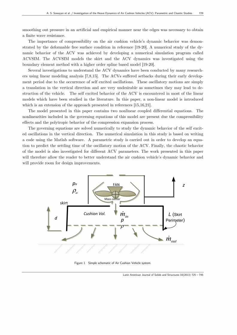
Numerous studies were reported in the literature regarding proper designing of these vehicles. During the 1960's and 1970's great amount of research work was focused on understanding the physics of full-skirted air cushion vehicles. Optimization in the design of the ACVs allows utilization of these vehicles for different purposes and missions. Figure (1) shows a simple diagram of these ACV’s. One of the basic components of the ACV is the skirt. Since the beginning of ACV designing, a lot of effort had been put in to develop a good skirt system. Excellent performance in terms of power consumption, stability, maneuverability can be guaranteed with a good skirt design [2-6].
In all these studies, the aim was to introduce a design for the ACV skirt system which should be amphibious and tolerant to unfriendly environment and terrains. Ma and Sullivan [6] developed a numerical theory on the linear heave dynamics of a two dimensional section of a flexible skirt and flexible bag-finger skirt system. It was found in [6] that the skirt system mass is an important pa-rameter in craft dynamics only at high frequency, which is close to the skirt bounce frequency. The skirt section in this study was constrained to move only in the vertical (heave) direction.
Chung et al. [7] described results of an analysis of the nonlinear heave dynamics of a simplified configuration chosen specifically to allow formulation from first principles. In this study, the skirt mass was lumped in the fingers, with the bag being modeled as a combination of massless inelastic membranes and links. Airflow processes were assumed quasi-steady, and the bag-and-cushion vol-umes were modeled as lumped pneumatic capacitances. The modulation of cushion air escape by skirt-surface contact is also included. In this study, the numerical results showed that nonlinear effects occur at wave input amplitudes expected to be encountered in practice. Also, at a given fre-quency, input amplitude increase caused jumps in heave response, period doubling, and chaos. Fur-thermore, results for two typical configurations show resonance at frequencies at which humans are most sensitive.
An air-cushion vehicle equipped with a bag-and-finger skirt using a linear analysis of the heave dynamics has been presented in [8]. In this study, a two-dimensional section of the cushion is sub-ject to pure heave or long-wave surface motion inputs. The skirt mass is lumped in the fingers, with the bag being modeled as a combination of massless inelastic membranes and links. The airflows from bag to cushion and from cushion to atmosphere were assumed quasisteady, and the bag and cushion volumes were modelled as lumped pneumatic capacitances. Their results suggested that changes in the skirt geometry cannot be used to radically modify an undesirable heave response, but reducing the skirt mass may be effective. It should be noted that air compressibility has not been included in their model.
Chung [9] investigated the pure heave motion of a two-dimensional section of the bag-and-finger skirt using a non-linear mathematical model. In this study, a simple model to account for the hys-teretic skirt surface contact forces was presented. The simulation results showed that the skirt force appears as damping, and confirms that the hysteretic forces observed in the static stiffness tests can
728 A. S. Sowayan et al. / Investigation of the Heave Dynamics of Air Cushion Vehicles (ACV): Parametric and Chaotic Studies
Latin American Journal of Solids and Structures 10(2013) 725 – 745
have a major effect on vehicle dynamics. However, they do not suppress phenomena such as period doubling and chaotic response to periodic input disturbances.
Fu MY et al. [10] had introduced a model for the dynamics behavior of Air Cushion Vehicles base on equation of six degrees of freedom motion control. In this study, the landing process actual-ly is the coupled motion among gas-liquid-solid three-phase intermediate value, in which motion- stance changes are quite dramatic and complex. Simulations in this study showed that, the greater the slope angle of the ACV is, the greater the pitch angle change during the ACV’s beach-landing. Also, it has been shown in this study that the pitch angle obtained by the air cushion vehicle’s land-movement is much smaller than the pitch angle made by the water surface exercise.
Pollack et al. [11] studied the resonant frequencies and mode shapes of the dynamic pressure within an ACV air cavity. In his study, a numerical model has been developed to predict the mo-tion of an ACV, with varying fan and skirt designs, subject to a range of ocean surface excitations. The model encompasses the complex geometry of the ACV and the three-dimensional variation of the air cushion pressure. The focus of the study is on analytical modeling of an ACV and its physics, to enable verification of the developed numerical model [11].
Yang et al. [12,13] had utilized of a Computational Fluid Dynamics (CFD) tool to investigate the dynamics of the skirt system of an idealized Air Cushion Vehicle (ACV) under non-linear break-ing wave impact. Modeling the domain of the fluid which includes water and pressurized air inside the ACV’s bag, had been achieved by using Smoothed Particle Hydrodynamics (SPH). The de-formable structural domain was modeled using the Finite Element Method (FEM).
A new dynamical model for small scale intelligent air-cushion tracked vehicle moving over swamp peat has been investigated experimentally and numerically by Hossain et al. [14]. They showed that the air-cushion system improves the vehicle performance by keeping traction coefficient of 71% and tractive efficiency of 62% and the developed model can meet the demand of transport efficiency with the optimal power consumption [14]. 2 PROBLEM STATEMENT AND MOTIVATION
In modeling the heave dynamics of the ACV, several sources of nonlinearities contribute to the limit cycle oscillations. These sources were identified and studied for an incompressible air cushion flow rate model in reference [15] for different air cushion geometries. Hinchey et al. [15] showed that the frequency of oscillations was low enough to allow the incompressibility condition to be adopted in analyzing the heave dynamics of the ACV.
A key factor in designing the ACV is to use the flexible air cushion skirt system, which is at-tached to the base of the vehicle from where the pressurized air is exited. The work presented in references [15-16] carried an analytical and experimental investigation of the oscillation dynamics in a flexible skirt ACV. Despite the presence of highly nonlinear sources in reference [16], Bernoulli model was used to model the flow inside the skirt of the air cushion ignoring the compressibility as well as the fluid friction effects.
Simulation of an ACV in waves was made possible by introducing a linearized compressible hy-drodynamic model based on transient wave Green's function [18-19]. It was shown in [17] that
A. S. Sowayan et al. / Investigation of the Heave Dynamics of Air Cushion Vehicles (ACV): Parametric and Chaotic Studies 729
Latin American Journal of Solids and Structures 10(2013) 725 – 745
smoothing out pressure in an artificial and empirical manner near the edges was necessary to obtain a finite wave resistance.
The importance of compressibility on the air cushion vehicle’s dynamic behavior was demon-strated by the deformable free surface condition in reference [19-20]. A numerical study of the dy-namic behavior of the ACV was achieved by developing a numerical simulation program called ACVSIM. The ACVSIM models the skirt and the ACV dynamics was investigated using the boundary element method with a higher order spline based model [19-20].
Several investigations to understand the ACV dynamics have been conducted by many research-ers using linear modeling analysis [7,8,15]. The ACVs suffered setbacks during their early develop-ment period due to the occurrence of self excited oscillations. These oscillatory motions are simply a translation in the vertical direction and are very undesirable as sometimes they may lead to de-struction of the vehicle. The self excited behavior of the ACV is encountered in most of the linear models which have been studied in the literature. In this paper, a non-linear model is introduced which is an extension of the approach presented in references [15,16,21].
The model presented in this paper contains two nonlinear coupled differential equations. The nonlinearities included in the governing equations of this model are present due the compressibility effects and the polytropic behavior of the compression expansion process.
The governing equations are solved numerically to study the dynamic behavior of the self excit-ed oscillations in the vertical direction. The numerical simulation in this study is based on writing a code using the Matlab software. A parametric study is carried out in order to develop an equa-tion to predict the settling time of the oscillatory motion of the ACV. Finally, the chaotic behavior of the model is also investigated for different ACV parameters. The work presented in this paper will therefore allow the reader to better understand the air cushion vehicle’s dynamic behavior and will provide room for design improvements.
zFANpa
Mass centerskirt
inm
outm
pd
aρ
ρ
L (Skirt Perimeter)
Cushion Vol.
Figure 1 Simple schematic of Air Cushion Vehicle system.
730 A. S. Sowayan et al. / Investigation of the Heave Dynamics of Air Cushion Vehicles (ACV): Parametric and Chaotic Studies
Latin American Journal of Solids and Structures 10(2013) 725 – 745
3 DESCRIPTION OF THE PROPOSED METHOD
The flow of air from the cushion in Figure (1) is assumed to be subsonic and compressed isentropi-cally. Also, thermodynamic equilibrium is assumed inside the cushion volume. Using Newton’s Se-cond law of motion leads to writing the vertical equation of motion as:
Mz = (p − pa )A −Mg (1) where M is the mass of the vehicle, z is the acceleration in the vertical direction, p is the inside cushion pressure, pa is the atmospheric pressure, A is the cross-sectional area of the cushion, and g is the gravitational acceleration. The total amount of air mass inside the cushion:
m = ρV (2) where m is the mass of air inside the cushion volume, V is the cushion volume, and ρ is the den-sity of air inside the cushion volume. The mass flow rate balance inside the cushion is:
m = min − mout (3) where min is mass flow rate entering the cushion and is a fixed quantity defined by the properties of the blower fan. On the other hand, mout is the mass flow rate exiting the cushion. It is depend-ent on the vertical displacement y as well as the atmospheric and cushion pressures. Taking the time derivative of Equation (2) yields:
m = ρV + ρ V (4)
The polytropic relationship between pressure and density for an isentropic process is:
pρ−γ = constant (5)
where γ =cpcv
, and the pressure is related to temperature by the perfect gas equation p = ρRT ,
where R is the gas constant ( R for air is 287 m2
s2K). Differentiation of Equation (5) yields:
pρ−γ − pγ ρρ−γ −1 = 0 (6)
or
A. S. Sowayan et al. / Investigation of the Heave Dynamics of Air Cushion Vehicles (ACV): Parametric and Chaotic Studies 731
Latin American Journal of Solids and Structures 10(2013) 725 – 745
ρ = ρ p
γ p (7)
Therefore the conservation of mass, Equation (4), can be written using the isentropic relation as:
ρVpγ p
+ p V = min − mout (8)
The variables in Equation (8) are all related to the cushion zone. Also V = Az , and at the cush-
ion zone ρ = pRT
, therefore:
Vpγ RT
+ pAzRT
= min − mout (9)
where T is the surrounding temperature. One can solve for p such that:
p = γ RT
Vmin − mout −
pAzRT
⎡⎣⎢
⎤⎦⎥
(10)
This model contains three unknown quantities, which are the vertical displacement z , the cush-
ion pressure p , and the air flow rate leaving the cushion volume mout . A third constitutive equa-tion is needed together with Equations (1) and (10). This can be introduced using the compressible Bernoulli’s equation [22].
v2
2+ γγ −1
pρ= constant (11)
The compressible Bernoulli’s equation is evaluated between the two stages, which are: the cush-
ion and the atmospheric regions. Therefore, the velocity of the air exiting the skirt is given by the following equation:
vout =2yγ −1
pρ− paρa
⎛⎝⎜
⎞⎠⎟
⎧⎨⎪
⎩⎪
⎫⎬⎪
⎭⎪
12
(12)
732 A. S. Sowayan et al. / Investigation of the Heave Dynamics of Air Cushion Vehicles (ACV): Parametric and Chaotic Studies
Latin American Journal of Solids and Structures 10(2013) 725 – 745
where p and ρ are respectively the pressure and density of the air inside the cushion region. Moreover, pa and ρa represent the pressure and density of the atmospheric air, respectively. The atmospheric air density ρa is related to the air cushion density ρ by the isentropic relations:
ρa
ρ= pa
p⎛⎝⎜
⎞⎠⎟
1γ
(13)
The Equation (13) is substituted into Equation (12) which yields:
vout =2yγ −1
pρ1− pa
ppaρa
⎛⎝⎜
⎞⎠⎟
⎧⎨⎪
⎩⎪
⎫⎬⎪
⎭⎪
12
= 2γγ −1
pρ1− pa
ppap
⎛⎝⎜
⎞⎠⎟
− 1γ
⎛
⎝⎜⎜
⎞
⎠⎟⎟
⎧⎨⎪
⎩⎪
⎫⎬⎪
⎭⎪
12
(14)
Therefore the outlet velocity is given by:
vout =2yγ −1
pρ1− pa
ρa
⎛⎝⎜
⎞⎠⎟
γ −1γ
⎛
⎝⎜⎜
⎞
⎠⎟⎟
⎧⎨⎪
⎩⎪
⎫⎬⎪
⎭⎪
12
(15)
The air mass flow rate can be evaluated using the continuity equation such that:
mout = ρaAevout (16) where Ae is the exit area of the flowing air. Substituting Equation (15) into (16) and taking
ρa =paRT
and Ae = Lz , yields.
mout = ρaLz2γγ −1
pρ1− pa
p⎛⎝⎜
⎞⎠⎟
γ −1γ
⎛
⎝⎜⎜
⎞
⎠⎟⎟
⎧⎨⎪
⎩⎪
⎫⎬⎪
⎭⎪
12
(17)
Making some manipulations and using the isentropic relations for ρa :
A. S. Sowayan et al. / Investigation of the Heave Dynamics of Air Cushion Vehicles (ACV): Parametric and Chaotic Studies 733
Latin American Journal of Solids and Structures 10(2013) 725 – 745
mout = ρ pap
⎛⎝⎜
⎞⎠⎟
1γLz 2γ
γ −1RT 1− pa
p⎛⎝⎜
⎞⎠⎟
γ −1γ
⎛
⎝⎜⎜
⎞
⎠⎟⎟
⎧⎨⎪
⎩⎪
⎫⎬⎪
⎭⎪
12
(18)
which yields:
mout = ρLz RT 2γγ −1
pap
⎛⎝⎜
⎞⎠⎟
2γ1− pa
p⎛⎝⎜
⎞⎠⎟
γ −1γ
⎛
⎝⎜⎜
⎞
⎠⎟⎟
⎧⎨⎪
⎩⎪
⎫⎬⎪
⎭⎪
12
(19)
or
mout =ρRTRT
Lz 2γγ −1
pap
⎛⎝⎜
⎞⎠⎟
2γ− pa
p⎛⎝⎜
⎞⎠⎟
γ +1( )γ
⎛
⎝
⎜⎜
⎞
⎠
⎟⎟
⎧⎨⎪
⎩⎪
⎫⎬⎪
⎭⎪
12
(20)
Finally the mass flow rate out of the cushion volume is given by the following equation:
mout =pLzRT
2γγ −1
pap
⎛⎝⎜
⎞⎠⎟
2γ− pa
p⎛⎝⎜
⎞⎠⎟
γ +1( )γ
⎡
⎣
⎢⎢⎢
⎤
⎦
⎥⎥⎥
⎧⎨⎪
⎩⎪
⎫⎬⎪
⎭⎪
12
(21)
This equation should be corrected by a correction coefficient c0 to account for some losses due
to the mathematical idealization of this model and can be found experimentally [5,18]. Therefore the mass flow rate equation can be written as:
mout =c0pLzRT
2γγ −1
pap
⎛⎝⎜
⎞⎠⎟
2γ− pa
p⎛⎝⎜
⎞⎠⎟
γ +1( )γ
⎡
⎣
⎢⎢⎢
⎤
⎦
⎥⎥⎥
⎧⎨⎪
⎩⎪
⎫⎬⎪
⎭⎪
12
(22)
where L is the perimeter length of the skirt shown in Figure (1). Equations (1), (10) and (22) are solved numerically in the following section.
734 A. S. Sowayan et al. / Investigation of the Heave Dynamics of Air Cushion Vehicles (ACV): Parametric and Chaotic Studies
Latin American Journal of Solids and Structures 10(2013) 725 – 745
4 RESULTS AND DISCUSSION
The governing Equations (1), (10) and (22) can be written in state space model representing a physical system as three first order coupled nonlinear differential equations. The state space form of the governing equations is given below:
z1 = z2 (23)
z2 =
AM
p − pa( )− g (24)
and
p = γ RTA d + z1( ) min −
c0pLz1RT
2γγ −1
pap
⎛⎝⎜
⎞⎠⎟
2γ− pa
p⎛⎝⎜
⎞⎠⎟
γ +1( )γ
⎡
⎣
⎢⎢⎢
⎤
⎦
⎥⎥⎥
⎧⎨⎪
⎩⎪
⎫⎬⎪
⎭⎪
12⎡
⎣
⎢⎢⎢⎢
⎤
⎦
⎥⎥⎥⎥
− pAz2RT
⎡
⎣
⎢⎢⎢⎢
⎤
⎦
⎥⎥⎥⎥
(25)
A computer code based on the Matlab software is developed to solve and integrate this stiff sys-
tem of first order differential equations (Equations (23)-(25)) using an implicit Runge Kutta method with acceptable accuracy as stated in the literature [23,24] that is suitable for stiff system of nonlin-ear differential equations. The implicit Runge-Kutta formula with a first stage that is described as a trapezoidal rule step and a backward differentiation formula of order two in the second step. Although, the accuracy of this solver is medium to low, we were able to have good results because we used a very small time step. Also in our solution, we were not concern about the most accurate solution because we were interested in the overall trend of the heave dynamics behavior of the ACV in the whole time interval rather than the actual absolute values of the solution. The solution to the system of Equations (23)-(25) is performed using dimensionless controlled parameters defined as follows:
L = Ld
(26)
M = Mρad
3 (27)
and
min =
min
ρav0d2 (28)
A. S. Sowayan et al. / Investigation of the Heave Dynamics of Air Cushion Vehicles (ACV): Parametric and Chaotic Studies 735
Latin American Journal of Solids and Structures 10(2013) 725 – 745
where L is the dimensionless skirt length, M is the dimensionless mass of the ACV, min is the dimensionless air mass flow rate and v0 is the initial velocity.
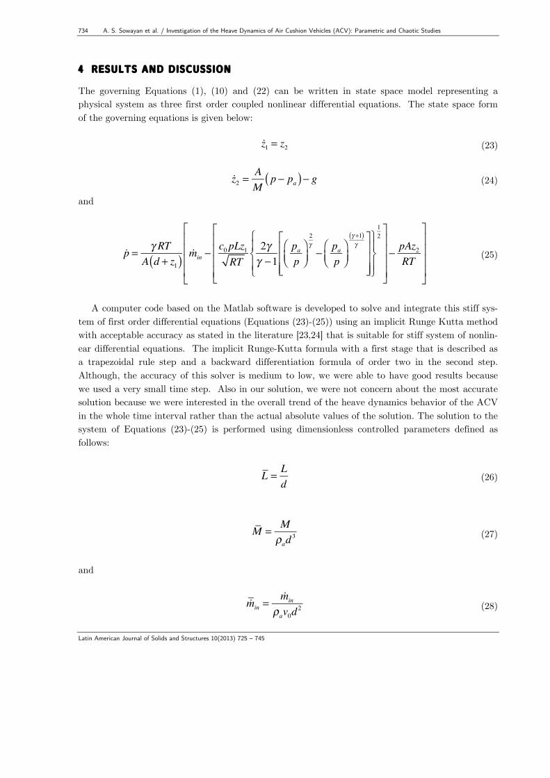
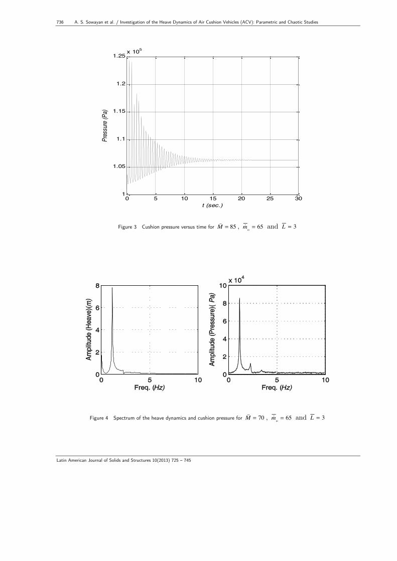
Without loss of generality, the results in this paper are obtained using the following ranges for the control parameters: M = 70 to M = 180 , L = 3 to L = 4.5 , and min = 25 to min = 250 . Sample results are shown in Figures (2), (3), and (4) for some selected parameters. Figure (2) shows a decaying time history for the heave when parameters M = 85 , min = 65 and L = 3 . The cushion pressure is also decays and reaches a steady state value as shown in Figure (3). In both figures, the oscillations cease after about 15 seconds. A good design for the ACV should reduce the oscillation history to a minimum. This will be discussed in the next section.
0 5 10 15 20 25 300.02
0.04
0.06
0.08
0.1
0.12
0.14
0.16
0.18
t (sec.)
Heav
e (m)
Figure 2 Time history of the heave for M = 70 , min= 65 and L = 3
736 A. S. Sowayan et al. / Investigation of the Heave Dynamics of Air Cushion Vehicles (ACV): Parametric and Chaotic Studies
Latin American Journal of Solids and Structures 10(2013) 725 – 745
0 5 10 15 20 25 301
1.05
1.1
1.15
1.2
1.25x 10⁵
t (sec.)
Pres
sure
(Pa)
Figure 3 Cushion pressure versus time for M = 85 , min= 65 and L = 3
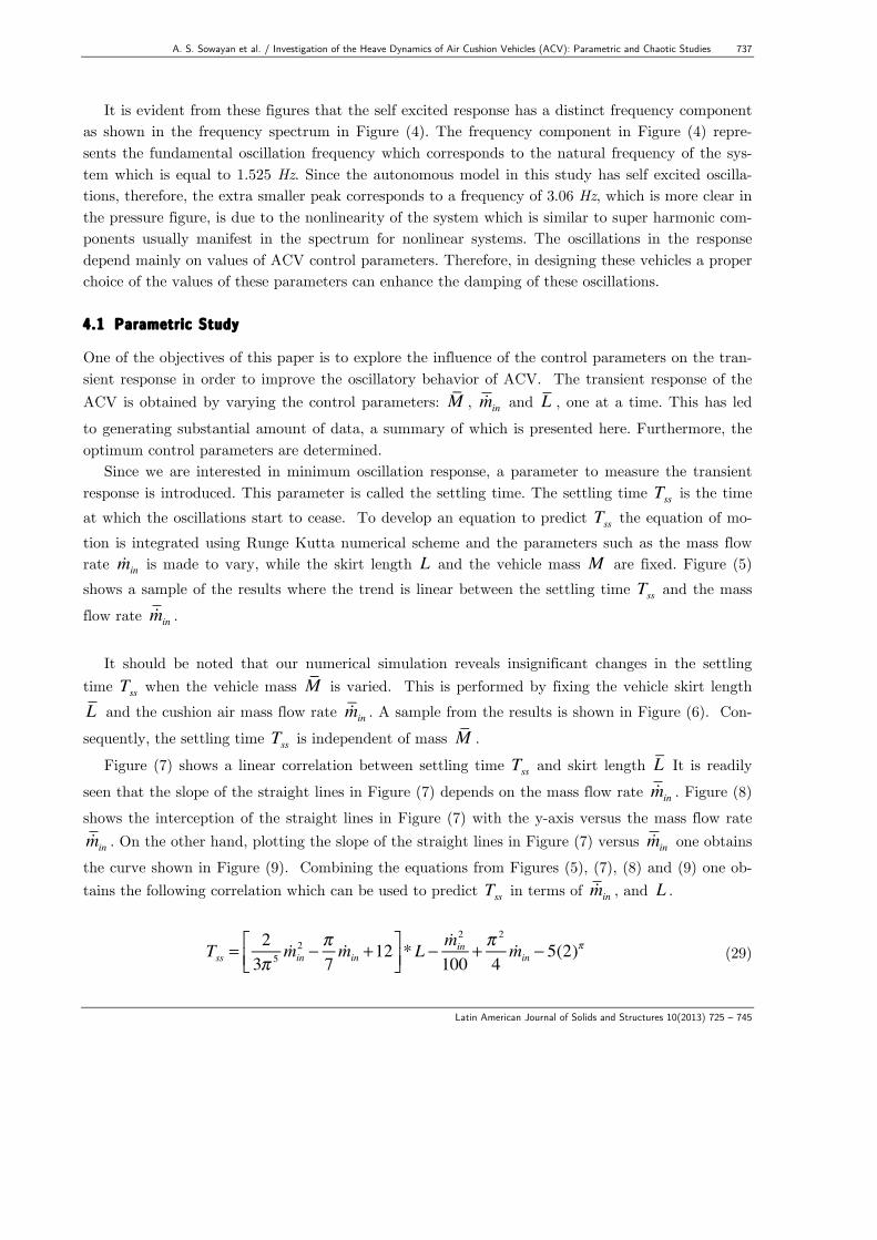
Figure 4 Spectrum of the heave dynamics and cushion pressure for M = 70 , min= 65 and L = 3
A. S. Sowayan et al. / Investigation of the Heave Dynamics of Air Cushion Vehicles (ACV): Parametric and Chaotic Studies 737
Latin American Journal of Solids and Structures 10(2013) 725 – 745
It is evident from these figures that the self excited response has a distinct frequency component as shown in the frequency spectrum in Figure (4). The frequency component in Figure (4) repre-sents the fundamental oscillation frequency which corresponds to the natural frequency of the sys-tem which is equal to 1.525 Hz. Since the autonomous model in this study has self excited oscilla-tions, therefore, the extra smaller peak corresponds to a frequency of 3.06 Hz, which is more clear in the pressure figure, is due to the nonlinearity of the system which is similar to super harmonic com-ponents usually manifest in the spectrum for nonlinear systems. The oscillations in the response depend mainly on values of ACV control parameters. Therefore, in designing these vehicles a proper choice of the values of these parameters can enhance the damping of these oscillations. 4.1 Parametric Study
One of the objectives of this paper is to explore the influence of the control parameters on the tran-sient response in order to improve the oscillatory behavior of ACV. The transient response of the ACV is obtained by varying the control parameters: M , min and L , one at a time. This has led to generating substantial amount of data, a summary of which is presented here. Furthermore, the optimum control parameters are determined.
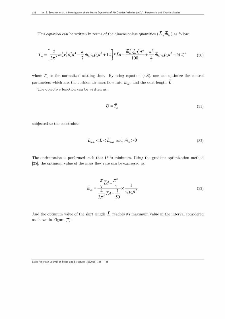
Since we are interested in minimum oscillation response, a parameter to measure the transient response is introduced. This parameter is called the settling time. The settling time Tss is the time at which the oscillations start to cease. To develop an equation to predict Tss the equation of mo-tion is integrated using Runge Kutta numerical scheme and the parameters such as the mass flow rate min is made to vary, while the skirt length L and the vehicle mass M are fixed. Figure (5) shows a sample of the results where the trend is linear between the settling time Tss and the mass flow rate min .
It should be noted that our numerical simulation reveals insignificant changes in the settling
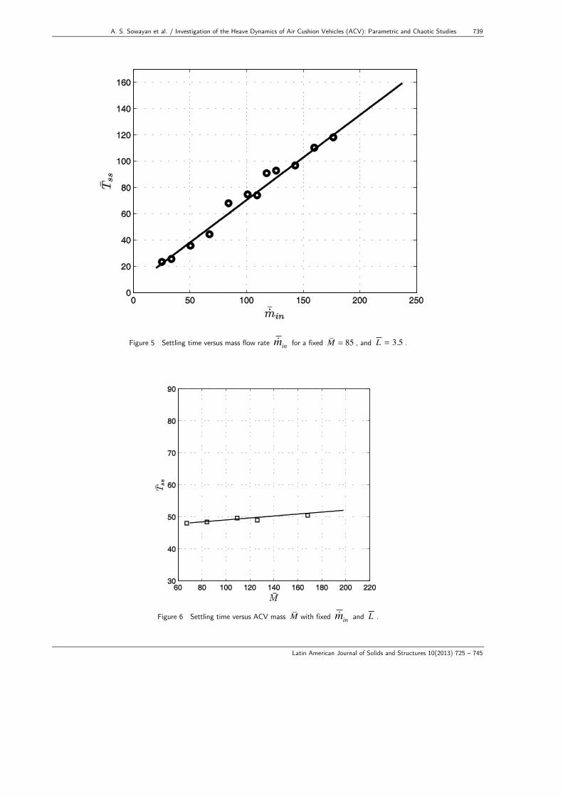
time Tss when the vehicle mass M is varied. This is performed by fixing the vehicle skirt length L and the cushion air mass flow rate min . A sample from the results is shown in Figure (6). Con-sequently, the settling time Tss is independent of mass M .
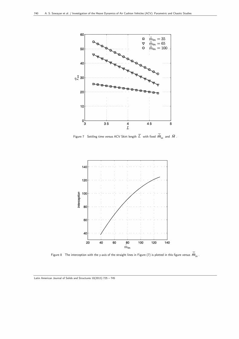
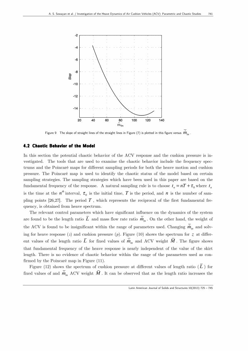
Figure (7) shows a linear correlation between settling time Tss and skirt length L It is readily seen that the slope of the straight lines in Figure (7) depends on the mass flow rate min . Figure (8) shows the interception of the straight lines in Figure (7) with the y-axis versus the mass flow rate min . On the other hand, plotting the slope of the straight lines in Figure (7) versus min one obtains
the curve shown in Figure (9). Combining the equations from Figures (5), (7), (8) and (9) one ob-tains the following correlation which can be used to predict Tss in terms of min , and L .
Tss =
23π 5 min
2 − π7min +12
⎡⎣⎢
⎤⎦⎥*L − min
2
100+ π 2
4min − 5(2)
π (29)
738 A. S. Sowayan et al. / Investigation of the Heave Dynamics of Air Cushion Vehicles (ACV): Parametric and Chaotic Studies
Latin American Journal of Solids and Structures 10(2013) 725 – 745
This equation can be written in terms of the dimensionless quantities ( L , min ) as follow:
Tss =
23π 5 min
2 v02ρa
2d 4 − π7minv0ρad
2 +12⎡⎣⎢
⎤⎦⎥*Ld − min
2 v02ρa
2d 4
100+ π 2
4minv0ρad
2 − 5(2)π (30)
where Tss is the normalized settling time. By using equation (4.8), one can optimize the control parameters which are: the cushion air mass flow rate min , and the skirt length L .
The objective function can be written as:
U = Tss (31) subjected to the constraints
Lmin < L < Lmax and min > 0 (32)
The optimization is performed such that U is minimum. Using the gradient optimization method [25], the optimum value of the mass flow rate can be expressed as:
min =
π7Ld − π 2
443π 5 Ld −
150
× 1v0ρad
2 (33)
And the optimum value of the skirt length L reaches its maximum value in the interval considered as shown in Figure (7).
A. S. Sowayan et al. / Investigation of the Heave Dynamics of Air Cushion Vehicles (ACV): Parametric and Chaotic Studies 739
Latin American Journal of Solids and Structures 10(2013) 725 – 745
Figure 5 Settling time versus mass flow rate min for a fixed M = 85 , and L = 3.5 .
Figure 6 Settling time versus ACV mass M with fixed min and L .
740 A. S. Sowayan et al. / Investigation of the Heave Dynamics of Air Cushion Vehicles (ACV): Parametric and Chaotic Studies
Latin American Journal of Solids and Structures 10(2013) 725 – 745
Figure 7 Settling time versus ACV Skirt length L with fixed min and M .
Figure 8 The interception with the y-axis of the straight lines in Figure (7) is plotted in this figure versus min .
A. S. Sowayan et al. / Investigation of the Heave Dynamics of Air Cushion Vehicles (ACV): Parametric and Chaotic Studies 741
Latin American Journal of Solids and Structures 10(2013) 725 – 745
Figure 9 The slope of straight lines of the straight lines in Figure (7) is plotted in this figure versus min .
4.2 Chaotic Behavior of the Model
In this section the potential chaotic behavior of the ACV response and the cushion pressure is in-vestigated. The tools that are used to examine the chaotic behavior include the frequency spec-trums and the Poincaré maps for different sampling periods for both the heave motion and cushion pressure. The Poincaré map is used to identify the chaotic status of the model based on certain sampling strategies. The sampling strategies which have been used in this paper are based on the fundamental frequency of the response. A natural sampling rule is to choose tn = nT +τ 0 where tn is the time at the nth interval, τ 0 is the initial time, T is the period, and n is the number of sam-pling points [26,27]. The period T , which represents the reciprocal of the first fundamental fre-quency, is obtained from heave spectrum.
The relevant control parameters which have significant influence on the dynamics of the system are found to be the length ratio L and mass flow rate ratio min . On the other hand, the weight of
the ACV is found to be insignificant within the range of parameters used. Changing min and solv-
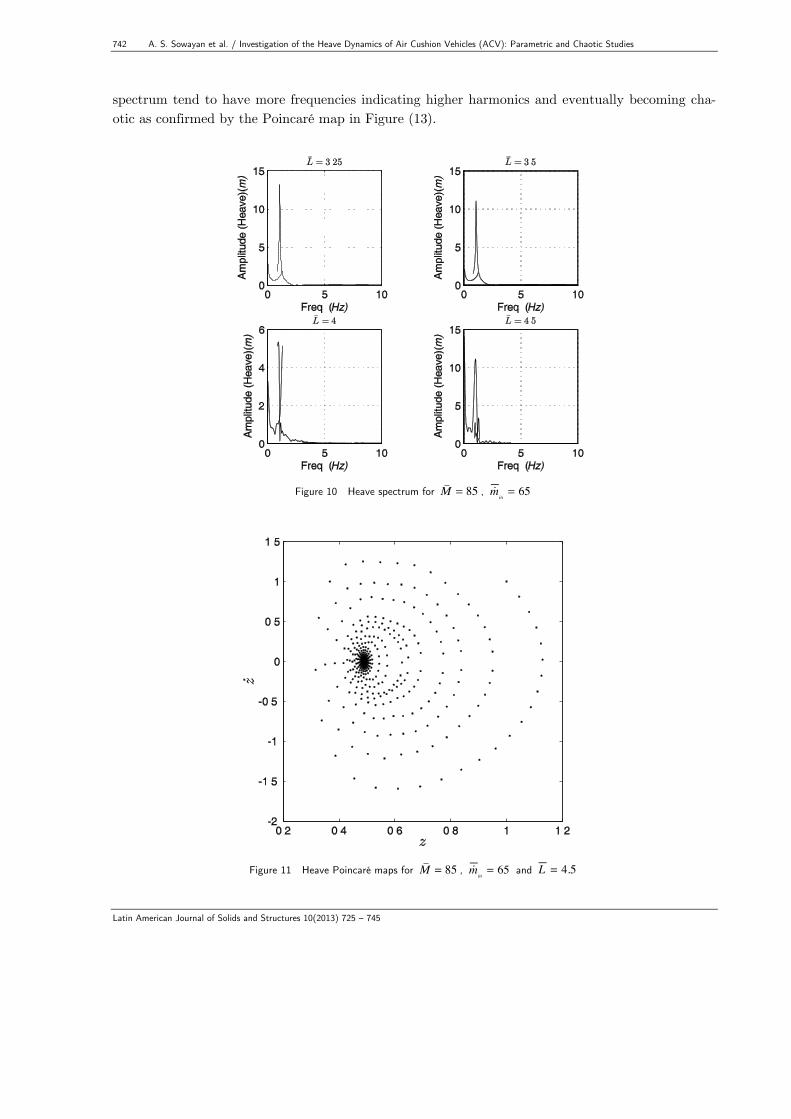
ing for heave response (z) and cushion pressure (p). Figure (10) shows the spectrum for z at differ-ent values of the length ratio L for fixed values of min and ACV weight M . The figure shows that fundamental frequency of the heave response is nearly independent of the value of the skirt length. There is no evidence of chaotic behavior within the range of the parameters used as con-firmed by the Poincaré map in Figure (11).
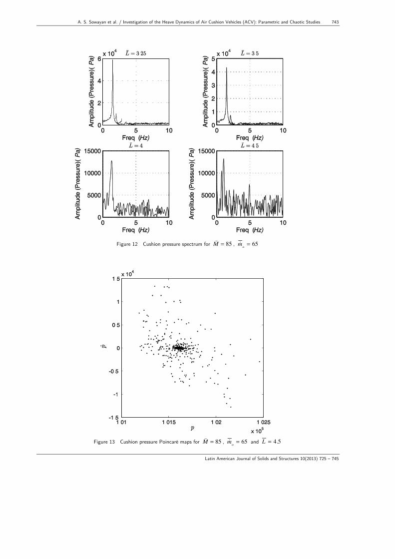
Figure (12) shows the spectrum of cushion pressure at different values of length ratio (L ) for fixed values of and min
ACV weight M . It can be observed that as the length ratio increases the
742 A. S. Sowayan et al. / Investigation of the Heave Dynamics of Air Cushion Vehicles (ACV): Parametric and Chaotic Studies
Latin American Journal of Solids and Structures 10(2013) 725 – 745
spectrum tend to have more frequencies indicating higher harmonics and eventually becoming cha-otic as confirmed by the Poincaré map in Figure (13).
Figure 10 Heave spectrum for M = 85 , min
= 65
Figure 11 Heave Poincaré maps for M = 85 , min
= 65 and L = 4.5
A. S. Sowayan et al. / Investigation of the Heave Dynamics of Air Cushion Vehicles (ACV): Parametric and Chaotic Studies 743
Latin American Journal of Solids and Structures 10(2013) 725 – 745
Figure 12 Cushion pressure spectrum for M = 85 , min
= 65
Figure 13 Cushion pressure Poincaré maps for M = 85 , min
= 65 and L = 4.5
744 A. S. Sowayan et al. / Investigation of the Heave Dynamics of Air Cushion Vehicles (ACV): Parametric and Chaotic Studies
Latin American Journal of Solids and Structures 10(2013) 725 – 745
5 CONCLUSIONS
A highly nonlinear model for the dynamic behavior of ACV is considered. A parametric study to investigate the influence of the control parameters on the dynamic response is conducted. The con-trol parameters that influence the transient response are found to be: the ACV skirt length and the cushion air mass flow rate. A dimensionless equation is developed to predict the settling time of the response. Based on the developed equation, the optimum values of the control parameters of the ACV are obtained. This can guide the designers of such vehicles to select the proper values of these control parameters for better performance. Furthermore, the chaotic behavior of the system is also investigated where the cushion pressure is found to behave chaotically when the ACV skirt length is increased. However, no chaotic response is observed for the heave motion. Acknowledgements The authors would like to thank the research centers of the Al Imam Mo-hammad Ibn Saud Islamic University and the King Saud University for its support and use of the University facilities to conduct this study. References
[1] Amyot, J. R., “Hovercraft Technology Economics and Applications,” Elsevier Studies in Mechanical Engi-neering, Vol. 11, Elsevier Inc., 1989.
[2] Jung, T. C., “Design of Air Cushion Vehicles Using Artificial Intelligence: Expert System and Genetic Algo-rithm,” Masters Theses, Ryerson University, Toronto, 2002.
[3] Chung, J. and Jung, T. C., “Optimization of an air cushion vehicle bag and finger skirt using genetic algo-rithms,” Aerospace Science and Technology, no. 8, pp 219-229, 2004.
[4] Zhou, J., Guo, J., Tang, W., and Zhang, S., “Nonlinear FEM simulation of Air Cushion Vehicle (ACV) skirt joint under tension loading, ” Technical Paper, American Society of Naval Engineers, 2009.
[5] Lavis, D. R. and Forstell, B. G., “Air Cushion Vehicle (ACV) development in the US,” FAST2005. St. Pe-tersburg, Russia, 2005.
[6] Ma, T. and Sullivan, P. A., “Linear analysis of heave dynamics of a bag and finger air cushion vehicle skirt,” AIAA 8th Advanced Marine System Conference, 1986, AIAA.
[7] Chung, J., Sullivan, P. A., and Ma, T., Nonlinear heave dynamics of an air cushion vehicle bag-and-finger skirt, Journal of Ship Research, vol. 43, no2, pp. 79-94, 1999.
[8] Chung, J., and Sullivan, P. A., Linear Heave Dynamics of an Air-Cushion Vehicle Bag-and-Finger Skirt, Transactions of the Japan Society for Aeronautical and Space Sciences, Volume 43, Issue 140, pp. 39-45, 2001.
[9] Chung J., Skirt-Material Damping Effects on Heave Dynamics of an Air-Cushion-Vehicle Bag-and-Finger Skirt, Canadian Aeronautics and Space Journal, 48(3): 201-212, 2002.
[10] Fu MY, Zhang HY, Shi XC, Bian XQ, Theoretical Analysis on the Operation Performance of Air Cushion Vehicle, SHIPBUILDING OF CHINA, 14 – 21, 2006.
[11] Pollack, M. , Connell, B., Wilson, J., and Milewski, W., Dynamic Modeling of Air Cushion Vehicles, Pro-ceedings of IMECE 2007 ASME International Mechanical Engineering Congress, Seattle, Washington, No-vember 11-15, 2007.
[12] Yang, Q., Jones, V., McCue, L., Investigation of Skirt Dynamics of Air Cushion Vehicles under Non-linear Wave Impact Using a SPH-FEM Model, 11th International Conference on Fast Sea Transportation FAST 2011, Honolulu, Hawaii, USA, September 2011.
A. S. Sowayan et al. / Investigation of the Heave Dynamics of Air Cushion Vehicles (ACV): Parametric and Chaotic Studies 745
Latin American Journal of Solids and Structures 10(2013) 725 – 745
[13] Yang, Q., Jones, V., McCue, L., Numerical study on fluid-structure interaction using Smoothed Particle Hydrodynamics and Finite Element Methods, In: Proceedings of the 5th SPHERIC International Workshop, Manchester, UK. June 2010.
[14] Hossain, A., Rahman, A., Mohiuddin, A. K. M., and Aminanda, Y., Dynamic Modeling of Intelligent Air-Cushion Tracked Vehicle for Swamp Peat, International Journal of Aerospace and Mechanical Engineering 5:4, 2011.
[15] Hinchey, M., J. and Sullivan, P., A., “A theoretical study of limit cycle oscillations of plenum air cushion,” Journal of sound and vibration, no. 79(1), pp 61-77, 1981.
[16] Sullivan, P., A., Byrne, J., E., and Hinchey, M., J., “Non-linear oscillations of a simple flexible skirt air cush-ion,” Journal of sound and vibration, no. 102(2), pp 269-283, 1985.
[17] Doctors, L. J., “The forces on air cushion vehicle executing an unsteady motion,” Proceedings of the Ninth Symposium on Naval Hydrodynamics, Paris, France, 1972.
[18] Nikseresht, A. H., Alishahi, M. M., and Emdad H., “Complete flow field computation around an ACV (air-cushion vehicle) using 3D VOF with lagrangian propagation in computational domain,” Computer and Struc-tures, no. 86, pp 627-641, 2008.
[19] Milewski, B., Connell, B., Wilson, J. and Kring, D., Dynamics of Air Cushion Vehicles Operating In a Sea-way, 9th International Conference on Numerical Ship Hydrodynamics, Ann Arbor, Michigan, August 5-8, 2007.
[20] Milewski, W., Connell, B., and Petersen, B., “Initial Validation of the ACVSIM Model for dynamics of Air Cushion Vehicles,” Proceedings of the 27th Symposium on Naval Hydrodynamics, Seoul, Korea, 2008.
[21] Burton, T. D., “Introduction to Dynamics Systems Analysis,” McGraw-Hill, Inc., New York, 1994. [22] White, F. M., “Viscous Fluid Flow,” McGraw-Hill, Inc., 2nd Edition, New York, 1991. [23] Shampine, L. F. and M. E. Hosea, "Analysis and Implementation of TR-BDF2," Applied Numerical Mathe-
matics 20, 1996. [24] Robert M. Corless, G. H. Gonnet, D. E. G. Hare, D. J. Jeffrey, and D. E. Knuth, “ On the Lambert W
Function,” Advances in Computational Mathematics, Volume 5, 1996, pp. 329-359. [25] Jasbir A., “Introduction to Optimum Design,” Elsevier Inc., 2004. [26] Alsaif, K., “Investigation of the dynamic response of a nonlinear semi-definite mechanical system,” Chaos
solutions & fractal, no. 15, pp 619-626, 2003. [27] Moon, F. C., “Chaotic and Fractal Dynamics,” John Wiley & Sons, Inc., New York, 1992.


![Air Cushion Vehicles [Bertelsen] Collectionsirismm.si.edu/EADpdfs/NASM.1994.0013.pdf · · 2017-11-27Air Cushion Vehicles [Bertelsen] Collection NASM.1994.0013 Page 3 of 10 Series](https://static.fdocuments.net/doc/165x107/5ae8c3757f8b9ac3618b8e3a/air-cushion-vehicles-bertelsen-cushion-vehicles-bertelsen-collection-nasm19940013.jpg)