Investigation of the effect of ceramic coatings on rocket thrust ...
27
General Disclaimer One or more of the Following Statements may affect this Document This document has been reproduced from the best copy furnished by the organizational source. It is being released in the interest of making available as much information as possible. This document may contain data, which exceeds the sheet parameters. It was furnished in this condition by the organizational source and is the best copy available. This document may contain tone-on-tone or color graphs, charts and/or pictures, which have been reproduced in black and white. This document is paginated as submitted by the original source. Portions of this document are not fully legible due to the historical nature of some of the material. However, it is the best reproduction available from the original submission. Produced by the NASA Center for Aerospace Information (CASI) https://ntrs.nasa.gov/search.jsp?R=19780018230 2018-03-17T22:44:50+00:00Z
Transcript of Investigation of the effect of ceramic coatings on rocket thrust ...

General Disclaimer
One or more of the Following Statements may affect this Document
This document has been reproduced from the best copy furnished by the
organizational source. It is being released in the interest of making available as
much information as possible.
This document may contain data, which exceeds the sheet parameters. It was
furnished in this condition by the organizational source and is the best copy
available.
This document may contain tone-on-tone or color graphs, charts and/or pictures,
which have been reproduced in black and white.
This document is paginated as submitted by the original source.
Portions of this document are not fully legible due to the historical nature of some
of the material. However, it is the best reproduction available from the original
submission.
Produced by the NASA Center for Aerospace Information (CASI)
https://ntrs.nasa.gov/search.jsp?R=19780018230 2018-03-17T22:44:50+00:00Z

NASA TECHNICAL MEMORANDUM
{NASA -TM-7 92) IN VESrIG ATIO OP CERAMIC COATINGS ON ROC KE LIFE {NAS A) 26 p HC A 03/ MF
E' THE EF FEeT HOT CH AMEER
0 1 CSCL 21H
INVESTIGATION OF THE EFFECT OF CERAMIC
COATINGS ON ROCKET THRUST CHAM BER LIFE
by R . J . Quentmeyer . H. J . Kasper , and J . M. Kazaroff
Lewis Research Center
Cleveland , Ohio 44135
TECHNICAL PAPER to be presented at the
Fourteenth PropulSion Conference
cosponsored by the AmerIcan Institute of Aeronautics
and Astronautics and the Society of Automotive Engineers
Las Vegas , Nevada , July 25-27, 1978
NASA TM-78892
G3 /20
N78 - 261 73
Unc l as 23337

o M ~
'" I W
I NV ESTIGATION OF TIl E EFFECT OF CERAMIC COATINGS ON ROCKET TIlRUST CHAMBER LIFE
by R. J. Quentmeyer, H. J. Kasp r, and J . M. Kazaroff
Nat ional A ronautics and Space Administrati on Lewis Research Cente r Cl veland, Ohi o 4135
Abstract
Two cylindrical r ocke t thrust chambe r cylinde r s were coated with a 0 .203 mm (O.OOS in.) layer of zi r conium- oxide using a process that mployed elec trod eposition of me t al t o a s pray coa t ed man -dr 1. The cy lind e r s wer e cyclically t ested using hydroge n-oxygen propellan t s a t a nominal chamber pressure of .14 MN /m2 (600 psia) t o show th e ef fec t of th e coa ting on life . Bo th cylinders fai led prema t ur ely due t o caus es un r ela t ed t o th e coa tings . One cyl inde r failed a t SO cyc l es because of a defective we ld and th e o ther failed at 659 cyc l es because of a blocked cooling passage. Pos t des tru ctive anal ys i s showed no cool ing passage wall defo r mation. Where e rosion of t h coa t ing occurr d , th e coating thi ckness s t abilized a t 0.061 mm (0.002 in.) wi th in SO cyc l es and r emained well adhered t hr oughou t t he t es t s. The hot-gas-side m t al wall t empera ture and th e th eoreti ca l maximum effective s trai n were r educ d by SO and 92 percen t, r espect ively, where th e coating wa s 0 .203 mm (O.OOS in . ) thi ck and by 40 and 50 per cent, r espec t ively , whe r e th e coa ting was 0.061 mm (0.0024 i n . ) th ick compared t o a n uncoa t ed cy l inde r . The 50 and 92 percen t r educ tions in maximum effec t jve s t rain r esul ted in th eo r e ti ca l lives o f 1900 cyc l es and gr ea t er than 10 000 cyc l es , r espec t ively , compared t o 300 cycles fo r th uncoa t ed cylind er.
I ntroduction
The curr ent g ne ration of high performance, r eusable r ocke t e ngines such as th e Space Shu ttle Main Engin e (SSME ) and th e Adva nced Space Engine (ASE) which i s a S9 kN (20 000 Ib f ) thru s t t ech nology development engine , are designed to operate a t high chambe r pressu r e t o r educe t he e ng ine size and wei ght. Howev er, high chamber pressu r e , cou pled wi t h ext er,ded r euse r equirements, impos ve r y difficul t cooling r equirements on th e t hrus t chamber , parti cularly a t th e throa t r egion. To m t t he cooling and life r equirements, th e inne r wall of t hese r eusa ble thrus t chambe r s a r e fab ri cated with r e latively high s treng t h , high co ndu c tivi t y , copper base al loys . This allows a wall thi ckne ss sufficient t o ca rry th e coo liag pr ssu r e and thrus t loads , whi le mai ntai ning r easonab l e wall t mpera t ur es and coo lant pr essu r e d r op.
Howev e r , as thrus t chambe r size i s reduced, by inc r eaSing chamb e r pressure fo r a giv n thru s t level , a cool ing limit wi l l eventually be r eached for conventional r gene r a tive coo ling; t ha t i s , ther e will no t be sufficient cool ing pressu r e drop available to maintain the wall t empera ture within its maximum operat ing limit a nd the thrus t chamb r l ife will be seve rely r educed. The SSME a nd ASE app ea r t o be nea r th e threE ho ld of th e coo ling limit fo r r eus able , r egeneratively cooled thrus t chamb e r s cooled by liquid hydrogen .
Presently, thes high pressure thrus t chambe r s a r e Iii limi t ed due t o th e high plastic
STAR Category 20 AIM 7S- 103 /,
1
strain levels encoun t e r ed in th e hot-gas-side wall during each th e rmal cycle. This high strain is caused by th e large ho t- gas - side wall to outer su rface (backsid ) wall t mp e rature difference th a t exis t s during th e burn portion of th e cyc l e. This r epea t ed large plastic s train appea r s t o promote progr ssiv th i nning of the coo ling pas sage wall a t the cen t erlin until th e wall thins t o th e point wh e r e it ca n no longer sustain th e pressure l oad. This phenomenon has been observed by several inves tigato r s. 1- 3 The r efo r e , if th e pres nt trend t owa rd high er ch amber pressur cont inues for r eusab le thrust chambers , coo ling schemes o ther than purely r generativ e coo ling will have t o be used t o r ed uce the high th e rmal s tra in in th e thrust chambe r wall .
One way to r educe th e t hermal strain is to use a th e r mal barrier , such as a cerami c coa t ing , on th e ho t- gas - side wall t o r edu ce the la r ge wa ll t emperature dif fe r ence . The use of ce ramic coa tings as an effec ti v the rmal barrier on rocke t t hrus t chambers is not a new co nce pt. It has been pr evi ous ly explor d by many inv s t igator s .4 - lO The major drawback t o th e us e of coa t i ngs is their t en dency to spall or flak off during rep a t d thermal cyc l es. This is due t o th e l a r ge di ff r ence in thermal coeff i cient of expan sion be tween th coa ti ng ma t e r ia l and t l,e me t al wall and th e low ductil ity of th e ce r amic coa ting . One me t hod of imp rovi ng adhesion of th e coating t o th e me tal wall is to apply multiple layers, or gr ad d coatings haVing various degrees of ductility . The objec tive is to have th l aye r which is applied t o t he me t a l wall high in me t al cont ent and t o have th layer exposed t o t he ho t combus tion gases pure ce r amic.
The mos t widely us d me th od of applying ce rami c coatings is by spr aying th em on t o th thrust chamb e r wall with an a r c plasma spraying gun. An o th e r me t hod is t o s pray th e coa t ing onto a mandrel and e l c trofo rm th e thru s t chamb e r line r t o th e coating. l l This r versed proc ss should pr ovide an improv d ce rami c - m tal bond beca use th e me t al is
l ec trodepos ited to a r ela t ively r ough ce r amic s ur face .
Sin ce th e curr ent trend i s t o at t emp t t o de sign hi gh pressu r thrust chamb er s whi ch ca n endu r e hundr ds of th er mal cycles , fu rth e r inv s tigation was warranted i nt o th use of c r amic coa t ings whi ch have th e po t ential of providing very long t h ru s t chambe r li f .
In ligh t of thi s , an e xp rim ntal investigation was initiated at t h Lewis Res arch Center t o s tudy th e e ff c t of ce r amic coa tings on thrust chamber life . The ob jec tives we r e t o: (1 ) valuate th e effectiveness of a zi r conium- oxide coating appl i ed t o a thru s t chamb r wall by th e el c troform ing p r ocess; (2 ) show th e r educ tion in s train ac hi ved by use of th e coa ting; and (3 ) r lat th e r suI ts t o thru s t chamb e r life.
The t es t apparatus used to p r form this inv s t iga tion was th cylindrical thrust chamb r

sembly . pr viously us d in th 1 w ycle f ti u inves ti tion report d in r ren e 1. Two cyl inder . abri ated rom I ctr d posit d copp r. nd oot~d ylindri I w II with zi r conlum-
or the te t pro rom. TIle ylinlly t sted t a chomb r pressur
o The results of po t
Cylindri
structur 1 an ly are or compared with l h re
rom r er nce 1 or an unc at d ylind r test ed at the sam nditions .
Apparatus nd Test Procedure
Th rus t Chomb r s s emb ly
Fi ur 1 sh ws a s hem ti c of th e cylindrical thrust hamb r assembly. Th thrust chamber consisted of an nnular inj c tor, a liquid hydr en
I d uter ylind·r. whi ch served as the test s cti n , nd a water-co 1 d c'n t rbody, hi h
ormed the annular thrust homber thro t. Th thrust humber had a c ntra t ion and expansi r tio o f 1.7. At 0 hamb r pr ssure of . l ( 00 psla) the thrust wa approximat ly 5.3 (l200 lbf). Gaseous hydro and liquid oxy wer used as propellants. y lindri al t st section was parately cool'd with liquid h drogen, which was disp sed f by a burn-o s tack. The cooling wat r for th- centerbody was dumped t th thru ~ t chamber exit.
Cylindri tion
TI1 cylindrical t 'st s 'cti ns w re l5.2 cm (6.0 in.) in 1 ng th and had an inside diameter of
.60 cm (2.6 in.). The rami coa t d cylind rs w r e abricat d by a lechnique simila r to that r eport d in r feren ell . The abri ation pr ocess, a shown in fi gu re ,wa start d with a 6 . 0- m (2.6-in.) diam t r steel mundr 1 . The mandrel was arc plasma sprayed with a 1 y r zirconium-oxid e. This was followed by an arc plasma sprayed Nichrom '
ating to provide an el ct ri cal ly onductive su rfac or th lcctroformin. pr ess. The tOlal thi ckn ss of th - z irconium-oxid -Ni hrom coa ting was 0.203 mm (0.00 in.) wi h th Ni chr me coatin acc untin for approximately 0.0127 mm (0.0005 in.) of this thi kn ss. Th mandrel ass mbly was th n plac d in copp r sulfa t platin bath wher it was continuousl y rot t d durin' th plalin ' op ration. After a sulficient I yer of copp r was plated t o th e assembly. the copp r wall was mach in d to the proper diamet rand 72 cons tant r ea co ling channels , 0.1 em (0.0 5 in.) wide and 0.127 cm (0.05 in.) high, wer mill'd into the copp r layer. The c ling channel wall was 0.08 cm (0 .035 in.) thi ck ,1Ild th e rib w r e 0.129 cm (0 . 051 in.) wide. Afl'r machinin , the colin cha nn Is wer ill d wi th wax and a copper c loseout
i ctrod posit d t the backsid. Th wax was then m It d out of lhe c oling "hann Is and th- mandr 1 was pr ssed ou t of the ass mbly. Fin 1 rna hinin· was p r rmed and the ma n i 0 lds add d. Th is m th od o abricatio~ pr duced a sm ven, zirconiumoxide surfa e having a surface inish of 2 microns (0 !Jin.) rms. Figur 3 sh W ' a c ros s - s c ti n of the c Linder w311 with th 00 ling cha nn e 1 dimen-s ions . The un a l ed copp r cy lind r had th sam g ometri conCi ur tior. as til ' coa l ed ylinder . rhe c pp r cylinde r was (abricat d b machining a Lin r [rom (\ orged c pp r bill t. The r s t of the
2
f b r ication proc 55 wa s th same co t d cylinder. Th cyLind r s b s p rately co 1 d with liquid n minal (low rat o f O. 1 (k '/s
In ntation
Th
of the ba ksid
as that for the w re d 8 i gn d to hydrogen at a
(2.0 ) bm/ s ) .
surfal.. . Four rib therm oupl s w re located at th thro t pi n of ea h cyLind r. 0 th rmo cou pl s w re l o-
t ed 0 . 0 9 cm (0 . 035 in.) from th int th coating and opp r wall and two wer 0 . 17 m (0.070 in . ) from th e interfac 0 the coating and copp r wall. On ylind r also had ei ht additional rib thermocoupl s, four 10 at d l.49 cm (0.5 6 in. ) upstr am and four locat d l.27 cm (0.50 in.) d wnstr am 0 the throat plan to ob tain an axiai thermal profile . Details of th thermocoupl locations r shown in igur 3. Th rib th rmocoupl s w r the sam as those des crib d 'n refer nee L. Eo h th rmocoupl consist d of a Chrom 1 and Cons t ant n wir 0.02 5 mm (0.001 in.) in diam t er insid a sh ath made of 0.3 56 mm (0.01 in . ) s tainless s e 1 tubing . Th junc tion was mad in a ball 0 silv r solder whi h was pia d with 0.005 mm (0 . 0002 in .) of go ld. Th pr b sprin load d a ain t the bottom of th Figure shows a c ated cylind e r with all thermocouples installed. The liquid hydrog n inlet t mp raturl.. was m asured by a platinum r sistan e brid transdu r inserted in th inl t manifold . The hydrog n outlet t empera ture was measur d by a Chrom l /C nstantan th rm couple ins rted in th out l t mani old.
lnle tor
Figur 5 shows th thrust hamb r inj tor . Gas ous h drogen and liquid xygen wer uS d a prop Ilants. Liqu id oxygen was inJ ct d through 70 sh w rh ad tub s arranged in two ci r ular rows, 36 in th inner r w nd 3 in the uter row. Th tub s wer made of 0.2 cm (0.0 I in.) o.d. stain-less steel having a 0.03 (0.012 in.) thick wall. Two cham cr pr 6:iU r ou t r r w of oxidiz r tub s. aseous hydrog n was inject d entir ly through the porous R g im sh fa e plate . Th ace plat wa s r mov bl ,s that it could b replaced if dama ed. TnJ cto r uniformity t sts w r p r orm d with blativ hamb rs and th uniformi ty was ound to b t risti e exhaust v lo ity rom
to 6 p rc nt.
Centerbody
Fi 'u r show th thrust l)(lmb r c nterb dy. The c ' nt rb dy wa s fabricated by ma hining 0 r c-
an 'ula r cooling chann 1.8 inl the out r p riph ry o a contou r d copp r al loy f rgin. TI1e cooling channels were c1. s d ut b -I' tr dep siling c pp r to the u er sut [ac and th n mochining lhe

slIrlJ ' ,' t o til<' Iln.J I ,', nlOllr. rh ..... · ... nll' rb d hud u .;.Ob ,no (\.b In . ) ".d In til<' .. ·,'mbll~l1 un Z,'nl' .Jnd.J
. J j ,'m ~ . I In.) 1I d. .It llh' lh r ,l .J l .. n<l W.ls I '>. ' .:. ,'m (b . O Ill . ) In I,' n ~~ lh I'h.'" IhlllSI1l1 h.Jlr-Jn'I,'
LIS 7. ". rhl) c \' ntl.~ rb~·H.tv \.o'~'!'t In i' rt\.'J thr('Iu~h rttl'
l,-'n t \.'r " t th,-' lIlJl'l' tr'l r .IIlJ hllill'd 1.11 l n pl.H' l.' fr III th,' h,1~k sid ....
0.0 7l> l ,' O. 1 ~7 111111 (0 . 00 l,' 0.00 '> III.
.~ i r\.·lJn l \1",- I "IJl~ t IdOl,' ~ Pl.t""l.' d \"' lh.tt Ing W .. t h .. 1J)pl u.~J tll tlh.' nUL!" h .I\.' . \l rLh,' " to rl' · hH, l" llh .. ' hl.' .. ll 10,1<1 .. Inll prllll'n~ ,1"", l:l.'n l~rlh,d\' II t\." 1'1 h .' l\.'n l\.'rbvuv \o,/ ... lS l.' lh'dl'd wlth .1 lh'lOllll.ll \,I~H\' r tl uw l,t C,.'I ', k~/s l.-'\,·
(1 2 lhm'h l'\.' . I'h ... ' w.lll' t l'nt\.'rt'U l hl· l.' l.'nll.'rt'h .. HJ Ih.'hlnd tit ... · 111 l"l.' t",'r, p.lsseJ lhr\'\1~h lh ... ' \.','0 1,"' ~:h .. lnnl.· l:, .Iltd W .I~ JUIllPl.'J .I t tht.' thrust ... h .lmbl.' l' l.' Xll.
rl.·~t F .h. llllV
rth.' l",'!'i t s "',' r ... ' l"lHllhll . .: ll.'u .tl t il\.' Ll. ... Wl h R' ·:"'.lr ch ·,'Il l,.'r r,h'k .... ' l l.· n~ll\l· t .. .-'s l.J('i lity. rht :-. ts oJ
'" dO N C,ll 000 Ihl) s.'J-I.'v,'1 rll,·\.. .'l t , ' ~ l ~ L , lnd
l.'quip!'I.' ...! \,'llh .. Ill ",'xhn\ls t- ~ .lS mut t ll.'r , 111 1...1 scrllhh ",,· r. rh l' 1.ll' lllt\' lIsl.'d prl..·ssurtzt:>d prnl .... ' ll.Jllt S l P r.I Hl'
tJll ks t ll :-ou r',,1\' th .... · pn,,'p""'11,ln t s .1"0 ltHll . lnt :, t,l thl.' thrust t...'h.ll11h ... ' r. F q.~l1 r ..... 7 IS oJ sel,,"'mLl l i .. , 1 t it ... • t .. ':, l t .J I.' tlllY s howtll~ th .. ' pr,'p\.'llJl1t Llnu t:,H.,lJlll ~lIp l'll" S .In,1 lh,' instrtlm.'nl,lll,H1. n,.' lIq uid hvdrl.,~,·t\ \I~I.'d l l' 1.',,(\ 1 t hl. ... l..ylllllJ..'r "'dS ulspl.'\:-Ol.·d l,t
lhr.'u~h .1 hurn-,'t t S LI,·\... 1'1,., lhrlls l "h. lmb"1 .',,-lI.lust ~. I ti .Iltd tlh' \.'l.'ntl'rh"J" "",'J ll' r CI.1t1l.ln l l.·r\.' ... ' ,,-p\.·Il","J inb' tll,' sl." rubb .... ' r . nu .... · t l.l th .... ' ::;111.111 V,dUlTIl'
1..'1 tlh,' thrl1st ehdmh \.' r l.·\,.lmh\.l:;lll.ll1 6!\,Jn .... 't .. In l':\o t, · rn .. l l ~t\.tl' r w.l S llS\.'J t ," b .. h.' k-I q.!ht t il .... ' ,,'CllIlhllStll.l11 dhlln
bl.'r. n,,' l ~ nltl.' r US l '''' ~J$ " lllih \"'\"~l.'11 ~IIHJ ~.IS l ·~"IlIS
h\'dr~,~ ... ' n .. IS prllp\.' ll ~lnl~ . Tl,,' q~llitil'n SllU r l.' ... · w.l s J hl " h v,'l l ,I" ., spJl' k.
All pr\."~$lIr\.'~ .. JnJ l ... ·mp ... · r ~l l ll r ..... b ... ) rl. t ('I." \.\rdeJ til Jl ~ ltJl 1..-1nll l'n.l m .. lg lh.' tl \. lLlpl'" tllr l.'ntrv Inlel
... 1 d l ~ ll..ll 1.'I.lmpll tt:'r. Thl' tl~lt .. ll r ... ·(ll rJln~ s\'s t,,"m W.J S s~ t Jl ~ hJ$i~ s ~mplillg rJ t ~ 0 1 !~OO word& per !':tl.'':~lnd . :\ltl."r rrll"' l"S:-' IIl ~ J .. 111 I.. .. t llll.' ddt ... ..Jnu CJ l--ulJtillns p",," r1 011Tl\.'d ~' n tl",' d.Jl..l I...l"luIJ b ... ' prin t ed out \,.' 11 th\.' ("\,.lntr~l l r l.'\.'lm t ... " Iln..ll .. H 0.1 s ... 't:,"Ind int .... 'r\'u I s.
Th ... ' -\' c l~ dh..1S CI1 h..'r till' t ... ',:; t~ "'as one wller ... • th () hl.' .. lt- ur p rti, n l.1 t h .... ' eyel ... • "'a~ IOIl ~ t."n ug.h f r Lh ~ hot - ~Js - s ld ... WJII t ... mp ... rJtur ... t o r ... Jch st~ ,"l d\' - s tnt (' J and "",'hl.' rt.' t ht." \.l"lll -J l "~n r rt ion o f th~ evell' "'3 I ... n~ cn("'lI~h l\.l brln~ the l. ... nlirl' cylinder ba ck t l" liq Uid h\'Jr""~","n tL' rnpl. ... r.Jt\ lr~. The c v c l ~ t o JChL~V~ tlli s \....onJ ltl ... n WJ S . ~ ec~nds In durati 1,1. - s("cl..1nds lr lm \ ~n ili \.ln t o the ... ' 11 0 l.f
the -('Imbusti o l1 p ,rLil'n ,,'1 th e ..:\'..:1 .... , and 1. 8 se -onds t.l brin ' th~ cyl indl.'r h.J~k t, liquid hydrog en t('mpl.'ratllr.... Th" liquid h\'dnll( ... n o l ant wu s c ntinuousl\" 11 we d thro\1~h out 0 ~\"c lll: (('s t, \11..)"' vt.:'fJ
tlle w~i~ht flo~ varl~d ir0m ilS ini ttal rJt~ ~s a lun~tlon f the h ... .Jt lOJd t o th ... ev l Lnd r ieal te s t sec t i0n. Fi gu r~ 8 1 0 displJ\" r m J ~o puter plo ttinG routln~ o l ch amb ... r pr~ssure and l iqllid h\'dr ~"n- lant "'ei, ln fl '" shl "' in' 11",,· th liquid h\'d ro'~ n w ... i'ht il W \'a r ied with th h ... ating c l
rin~ t h ... first evel... 1 any g iv n t s t a liquid hyd rl~~ n p r c l was II I'd l bring n ... entirl.' cyl -
3
lnder LO I iqllid h dro' n t mperutur ... bet o n ' i 'nlti on II th ... Lhrust ch mbe r propl' lldnL s. ShorL Ll'b l , consis Llng u l JUb t two e ll'S , w"'n' mad,· with' eh n ... w ,vlind ... r t l' Lab li s h lh ... dl'slr,'d le s t "ondiLlon. Aftl'1 th e deslr 'd l,'S l ... 'ndl rl ,'ns we rc :.ldl i~v(.) d, th co tit rUh t d, Ontbl" r wa l' Ul1l i nllnll~ 1 y .. ' c1,'d lInltl th ... s upply 0 1 liqUId h dnl' ,' n wa~ n,' arly d,' pl,' L,'d. ,l'n.' rall, 7 0 l O 0 , I l'S .ould h,' .Ichl ... v ... d on <>1H' l.lnk " r liquId h."drogl'n.
A s lid s t~ c ti m0r, LlccurLltl\ dnd r~p~d l Jhll '
LO 0 , 0001 s l'cund wa~ lI s l'd l O pro ' r m Lh .. l "h l "'Vl'nts. Fuel and lIxidtz ... r flow s were ~onll·"I Il'd by initial I sellin' iXl' d valv ... P" S lll t n s whilh would nominal I SL' t chJmh ... r prl's s un' ,mJ mi" tur l' r.Il11I. All,' r th e nom 111" I ch.:tmb ... r pr 'ssu \"(' wa s n 'JlhL'd, hoth ch"Jlnher pr'ss url.' and m tXl llrt~ rati o W'-' l l' .. ldJlIst ... d t the d ... s ir ... d condi li on b .:t clInlroll ... r . 1'1 .. , liquid hVdrog ' n coulan t wC' il(ht 11 0101 nd prl's-s \lr,-' W\..' fl.' s, t b 0 ellmbin .. lli on o f tDnk prl'hSlIfl.· , dnd lipS l r,' am and d wns l r,'um va I v ... pos ill on s. fh, c ... nt ... rbody Wdl ... r fl W wa s se L lo i l S md.i m,~ Idle b I'r ... ss ur~ .: in g thl' w.JLL' r lun k t o OJ pr 'ssu ll' 0 1 10. tN/m~ (I 00 psIJ).
Ttlt.' tl.'slS W' rl.' m ntll.lrl.-d bv d ( I OSl'O-l i r elit t l,' I.'v l slon ca"",ra and d tl' s t ' · ... 11 ml c r opl""'l' . n", rv Jnd "'ll lli c OU lpllt s w~r~ rl'co rd~J J Il m~~lll·tj~ t~II)'
l or I'Ll b,ICk. Fl);url' shu,, 's LhL' ,v llndrllJI lhrust dIJmb.' r dUrI,1' Lhl' ,'ombus tl n porllon 01,1 l.' v c li c ll .. '!j l . rll\.' c.y lintll'rs w,,' rl' inSpl.·lll.'J .J lt lr l.'J ... h t~ s t Sl rll.'S lO llbs t.· rv,-' lil\.) l.' {lTlliiti l n ot tlH'
\..'uD tln ' .
I'Jb I.' I );1 VL'S d ~u01l11ary "I l hl' ll' . l n'sld l S, Bn th z irc onlllfll-l' Id,' ,,' ''ll'J .. v lind,' r s l ol li ,'.! pr,' m,llllrl'lv, hUl nOL dm' l l' I.ti Illn' "I Lh ... .:ua tl ill' . C lind ... r 51 3b t oi l l'd o ll ' r lInly 0 ce i l's dul' LO .1 rial.' in a m.:t nil o ld w,' ld s am near lh l' illj"Llllr. Th ... fal lu r l.' Lali S 'd UIH,'p(llrabll' domagL' and t h, l ,·"lIn ' wo~ L rminat ... d. C' lindl' r sl 17 h.Jd a burn,'ul f ... i1ur' in tto ... Lhroa t r "!\ 1<'n du ... Lo a block,'d U 01-Int; pol SHa!;... lIoWl'VL' r, lh,' fa c L tha t lhi s l·y lln.!, r ... ndllr ... d b5 cvc l ... s 0 1 L ... Sl Illg b ... fore Jilllre .. mph.1si ze d th ... S i 'ntfican l l'!fee L hu L e ollngs ean hJv ... o n p r I nl(ln ); lhrll s l chumbl'r l ill'. Cv li nd,'r Si N ~ d~vl.'lop ~ a e r a k in lh ... lhrou t plan ... dl 2 10 cy' les a nd wa s LVpi ' JI o r tlH' :Ii I lir e ml 'dwnlsm l."ncount e r eu in til ... , hl ·h s lr.l in envi r nlTI("'nl ot l h .... ,s,-' LVp l'S 0 thrust chumb ... r s .
Pus t AnJlysb
After the L s ting wa s c mpll'l ... d, cach cylinder W.J S su bJe tl.'d to J post t ... s t deslrllCllVl' JnalVS I". 111l' ylinders we re sl'l' t iolWd t o dell'rmint' lhl' ..lmount of def a t l n in Lhl' c 0 1 ing pussa); wall and t .) m'asu re till' (oa llng tid Kne ss .
B th th ('
pl ... t Iy inta c t. FI lIr cy l ind r SI sh in ' th ...
o ung . n1e thr at plant' In Lhib i 'u r ' is thl' s ecti n plan th at nt..lln th ctllpll'
cent rlin s. Appro ximut Iy 55 pl' r c ... nl oj Lh e a ting remain ed c mp l ' t el' inlacl Ln Lh lhro t
ion.

Fi'ur" l2 Shl s tIll' burnout 'lr <'a in th thro8t. re~ion of linder SI N 37. Durin ' t.hc d s tru tive analysis, th cy linde wa s lit Sll th.ll l' russ s"c-tl n th e co lin' passage in which lhe burn ut oc 'u rrcd c uld be exumi.Il<'ll. ll'~ S [l'"nd th I the C) ling po sa'e "'..ts cnmpll' l ely blu..-kl'd with platl'r"
101 8t tw l ocacll'ns. CUllsl'qu'nLly, l hl' 11nly c: l-i n ' provid d t o dli 5 passu ·~ wa s due t u the h eat cundu c tion throu h t he clippe r liner t the djac'nt co ling pa SSel 'es. f'igur ... 13 shnw$ thl pl a t e [" . Wlll< in the 'oo lLng po s,.I'e. It ;:ts l'on'luJed th'lt the hot s pot call ed th e co ling passag' w..tl l t l' l oc a l I ,md progr sSive l y de ,)[111 durin~ thl' <,yeli.: testing untiL ch~ c a ciny could n l Inge r ;:tdhere t the .:: pper wall. n ee this 10c.11 ,In:~a was exposed to che ho gas, J burn u o 'curred ()n ch ... 659 th c cle.
C 37 sh wed l' l'OS l on in the thnat regi n eylindl'r SIN 30 . Howev e r, dlle lo thl' g r >o ter r of cyc les ",xperil'nc ' d b 'yl ln-Jer SIN 37, nly ab ut 0 percent ot the "ogin.Jl c acing sue :1 C~ relU,\in.?d inc,":l .lS ':"IUpJred t o 55 perc !It (r ylioder S/ J. Flgure 1 ... show, the lInifonnly cr <It'd 'outin ' urlact:' i n the l hroJt re-ioo t 'y llnd e r S/ 7 . Ex~ludinG h' burn d ou t or a ()[ cy linde r sl 7 , Lh e r e 'hIS no o th el a r ea on ('lthe r o.:y l imll' , when' bJ rl' coppe r 101 .1,; I'Xpo ed due t o [..li l ll r ' uf he coaLin t: Jdher'.
The m~J ·ur .... d rib Ll'mper.Jtu l· ... :; show ... d thol motit of the erosion in bO lh cylinde r ,; oc.:u rrl'ci during the initial 80 c eles llf te'sLing . rl lis " '<1S e v i-tI need by thl' ob st:' rved rib ten1jpratlll'I'S in th dredS where ' rost n 0 ·C'urrt1u. Tt.'mperaturl..' OJLa tram ,1 throa e th e rm COUpll' in cy l indel' SIN 37 showed u continuous incl'CJS~ in st0udv - st~t0 t~m
perature' La 3bol.t 80 cycles indi ',1 ling till' " <Hing e r s i a n wa s taking pl3c. (\l' 'ond th iS, howl'ver, the steady- s t,ll e t 'mpe' rdtur c stilbUi.!e'd ind1 '.lling Lhat erosion was n o l onger lH;curri ng in tlHI l l'e~ion
as shown in fiAut'e 15. Alth ugh cy l i l1d,'r SIN Jb was tes t e d [or only ,0 cy.:l('s the SUml' cl1..l rJ l' t ... rlsti c of initi3L e r osion WilS ob erved .
TIle ootlng th ickness wus meosu re'd ill the s lO blii z d e rod ed regiuns of bach cy l imkrs .lod "',IS
found tll I e a unlfonn 0.0 1 01111 (0. 00:" in.) in ' Luding the thin Ni , hroml' lil e' r, TI1l' 'rodl'd l' atl n ' in these areas oPPc.lced Ln bl' ve r y ,yell .J11I1l'rl'd, hoving a su rface r oughness of 8 . La . 7 mien ns ( 40 toJ80 " .lIl.) rms .
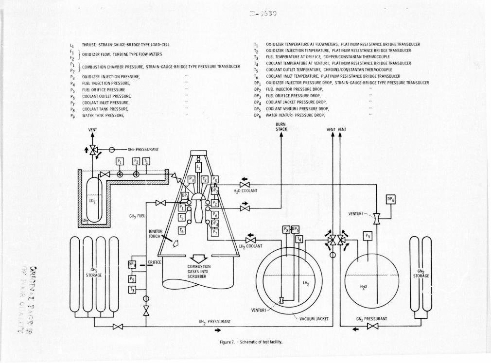
Figure L6 s h '''$ ;1 " r uss se Lion 1 ,ylindl'c SIN 37 t1 the thro t 1'1 ne a t ,\ <:ir.:umll'r" llt iu l 1 -co tion ow y r om the' burnol't r ... giol1. The coati ng ut this 1 cJtion h.J s ,' roded L th e a.Ohl mm 0.0024 in.) thi cklws!;;. rhc unil onl1iL~' o[ the 0(1 ing an he 5("n in t1 ll~ i'lguro.!. ltl' th a t
the' r i s virt ua lly nu dl'!nrm.ttiol1 ,)1 the coo lin ' pass a 'e5, eve n J! It!r b59 thermdl cy<..lcs . COmpdl'l! this fi'llre wlLh the c r oss secLiun 01 un ·" ... ted cy li nde r I J sh wn in fil'url' 17, which dl'velopl'd J
c r ock in th ' cooli n~ p.Js:;dge wall" ~10 .:ycles. Thl! s verely def nned C (lling. pass,\!-\ 'S (lr ' t ypi ' ul of th e failure mech nism rl' porl ... d in r ... Lc'l' n c I, th t L . chinning of th' ,0 Ilng pJssag' wall <It th cen t erl in e unti I a ruptun~ lC urs . It wa s mcnti n d pc 'vious l y th,lt 'ylind ' r SIN 37 all'd prcmatu r ... l y due t blo ketl cooli ng pa ssoy .... Howevc r, i ( the n ' had b en no b J ock"d l'O I ing passag' , on could con 'lud<' lrom fi uc.;> 16 th a t he' cylindl' r wou Id hnvl' e'ndurl'd g ,'v l' ral hundred marl' cyc les. The l'frN' Uven '55 I th ' coa cin!-\ In proLonging thru t chamber life can r·adily be see n
fr m these tw li ur S.
Therm 1 Analysis
On ' o f th obJl! ctiv(>s 0 1 this pr gram 1.1 t o h 101 lh ' redu c tion in strain Lhat auld b' chiev ... d
in th e thru t chambe r w!lll hy us' f (I ch nnal barrt er cOl1 l ing. ln ortll'!" t o perfnnn the n c ... ssary s tructuro l an..tl bis, the 'y Jlnd r r S - st" ti nol temperatu r e profile as J lunction of Lim' was r'-uired.
rlle' tollowing pro..: ... dure dlc cy llndt'r r 5-se·t10na[
r tht.' s tru c t ur:ll an a Lyses ; and b.l ckside tempe ratures, ere pi tted as a [un -Lion o l tim l o r c ,] ch cy linder; (2 ) a t hermal m de l 01 the cy linder wall c coss Be ci n waR d vel-
ped; (3) th e hounder conditi. ons need"d r th ' c ndu Li on an iysi were co l cu lot 'd; and a two -dime nsi nal ndu cLlon ,lnolysis WI] p ri. m1£'d using tIc SlNDA L2 thennal an..Jlyzer prog ram until u best muL h f th e -xp~rim nt 1 nd th or tic 1 rib nd ba c ksid e l cmp'rotur es cou ld b achie ~d.
Due Co the l a r e BlUou nt o l dot3 ohtained in he "pt'rlmcntol testing, a d tailed on lysi s using
thl dala Lrom e v e ry cycle 1.1 S not possibl ' . "wever, random samples 01 dll of th e mcllsur(>d paraml·tl rs "ere taken lhrnughou t th cyc li t es ting of l'a b ylindcr. Anal sis o f th e do tD ' nflrm..:-d that Ont'l' th~' desi red eycle 1.10 es t oblished r a given cyl inder, the t est par,meters remaine essentiall y thl :i ml' thr u!-\h ou t the t,'s ting , Thus , i t 1.10 on -clud ... d Lhot ny cy' le w;:t s rlpr~ ... ntaclv of "nllmi na l" 'yc I.. th roughou t the cy 1 ind ' I' L i. c.
Figure' 1 shows th e experiml'nLa l rib a nd ba c k-ide t emp,'ratu l'l' da to at tl1l' throa t p lan e [ I' ch '
203rd eye II' ol un,' ,It l'd l' Lind r sl TIl t 'm-per turt'S [rom th,' rib them101'0upl es located 0.0 <) t;m (0.035 in .) tram the h t-ga· - Side wall wcr ~ ~V0rJg0J. In like 01 nncr, the 001p e ruturcs [r In thl' rib them1o":llupt s lo cated 0.178 em (0.070 in.) ill depth were Dvnraged , and die t empe r tures fr m Lhl' lour h:J~ksid,' thl' rm couples were averaged. Als shown in this I igure Is the c 1 1I1nted match 0 1 th e rib Dnd ba kside t 'mpe[atllr data and lhe thpm),ll model USI't! in th .:> c ndu c ti on a nalysis . Du tll s)'ltm),' try, (In ty one - Iwlt of a co ling chonne I wull ' cos" ' ct: t i n Will. requi r -d (,)r til ' m del " 5 s hown in l igure Th' r pr 's ... ntutive 1.10 L t ' r oss se~tl n wos divid ~ into elem nts Wl lh a t emp r-Itllr C' n"de at th ~ ' e nCl' r eo h e Lement . In addi-t! n, Liter ' wer" surru 'c nod(';; n eo h of th lc-men t s oLong th e mod ' l bound.lcles. The relativ~ l oc.l tions o t the th l'n110coupies "se d t o co lI c C th experimen taL t rnperAture da ta ar~ oLs i ndi ca t ed in thl figur. Input to the SI DA prog ram r qui rl's th ' hot-gus- ' id .lnd c"" Lant-sid e boundary o ndit iuns .J s a [un L10n 01 timo.!, so that a temp'rJtur pru ! ltl' 0.;.1\1 be gl'nl·r.1tl'd a>; , lun' ion 0 1 tim. Thl' . t .... )d . s t (1te IHl t- gos-sid heat Lrons c r o<,(£ic ient w.s obtained from un r ep rl 'd doc using u olorimeter with the eyl indri ' ol t h ru S L c hamb r
c nfi gu l'ation. The . t ... ,ldy-stoce co lont side heat tr;:tns e r cOl' ffid"nl was e l cu l otl'd r om em, 1r1 o l . rc,' lati ns whi ' h '5t deB e l lb ' c nYC tiv h 0
transfer t o liquid h ydro·en. [n additi n, o lont-sicle heat lr,lns t ' r c ' ffl ci ' nt wa s
Dr und the co lin ' chunnel pecipher t t he var int lo n due to the d 1 t le r ' nt wllil tures Lh a t l' xi.st !lcound the pl'dpl)'ry.

M.lS-sid' and th coo lunt- Id ... Iwat tr n f r i-cI .... nts dllrin' th ... t ansi nt s "'I.'re n t av Hab l e tr m ~xperlm~ntaL dnt~t lher~ to r~, os an iniLi 1 lnpllt, they were as unll'd to v"ry [ r om thl' ir s t · ody-tate valu ... s in prop rti on t ' variations i n chlmbl.'r
p r "'bsUrl' and Uqll!d hvdn, ' l'n "'l'i ' ht l ow l r C'a h time sUel'. Plots 'HI, h a ' s hnwn in [i'lIre were lIs ... d t o mak' th ' .JdJustments In thc' hc'a t transler enl' llei ... nt s dllring th ... tr ansl ... nt. TIli s pro edll r l.' did J rc·.Jsonabl e Job III Ii tlin M th,' t ·mp ... rilture da ta, alth ugh minor ,ld Jus t me nt s ",,'rc' m.ld ... ill th e boundary c ndi t ions, ",I",n' 1I ... ·dl.'d . t o bC's t fit tl1' dlltll. The sr DA pro' ram is c'a pilble 01 pl.! rfo rmin ' n thrc· ... -dimc·llsional th ... nnal JIIJlysis , but only 0
tw -dilnension.11 n alys i s il t t h .. hrout plane o( th ... th rus t ' hamb ... r wa s usc'd l or th is wo rk . The pro:trJ.m o utput s tht. ... t empl' raturt..' [ o r ('tH:h nodal point In th ... m del, hClwl.! v,·r , In ll'ur ... I onl til<' m.lt .:hi ng 0 th ... t ... mp ... ratur,' dJta and th l.! pr jec t ... d hot- gos - ide wall t emper .llUre is shown . lIst n ' this tt! chniqll L' , .3 -o r sS-bl'ctionol tempt?ratllrt.. ... pro il~ as J tuncti n t time ou ld be KenerJted I r each cyl inder.
it wa s assumed that hl' bl'st projectc'd hotgas-s ide wa II temperature wa s ,bt.lined when th ' colc~llated t l'mpl.! ratu re d..Jtn ma t c h -d thl' I.!xperime nt a l d.lt .1 (th,' th ... rmocollpl,· l' l ses t t th e h t-gas wnll. \"h~n tillS w,s d ne, a per l ec t ma tdl ,[ the thermocoup l e d.l ta at th e 0 her two l oca ti ons cou ld n t n~ ~ssarily be ac llLeved , as s~t?n on iAure 1 . n l i s wa s probJbl dul.! t o axial condue t ion I.'f l ... e t s no t ac ou nt l.!d l r in thi s two- dim"nsionJl ,l nJ1 Ysis.
Figllre 19 shows t h" edlcula t "d m.lt hing of th,> rib ..Jnd ba~ksid l.' temp"raturc datJ lor cylinder SiN 37 .It t he ll(th 've I l' , be ore any f t he eoatin~ hud I.' r od('d away . Thl.! rib .lI1d bJckside t "mpl.' r a t ure data w\? r ~ avcrog~d in th \.' s . ..11llt? m .. lnlh.) r JS the d~lt.J
(rom c linde r 'I N The wl'rsh01t in th" t ('mpe r-Jtl.lrc da t a was C'OliSCU bv a slight I..'vc rshol,)t in chambe r pressure cncoun l cr\,. ... d in t ht..'Sl' \,. ... sts. No tl' th ~ lorg~ d~c r~as~ ill l tlC cuLcuLa t cd stL'Jdy-S l OlC h t- g a~-sidc m~ t Jl w.Jll lCmp\!r.:alllrc , fm\." \o,'h'll ("om pJr"d t th l.! unco..J t l.'d cylind ... r, VII.' ml.'tJI wall tl.!mpera t ur was r"ducl'd f r om K (1520 0 R) lor th e uncoated c lindl.!r to on lv 17K (2 2 0 R) for the oa ted cvlinde , J r~Jucti 11 ol ~O pL'rc~ nt.
Alth ugh not sh wn on th,' I i gurl.', th,' ca l cu lJtl'd hot- as-~idl.! ce r amic wa l l tl.'mpl.'ratllr .. WdS 2 22 K (51000 R), whi h is elos,", to th.., ml.!lti ng t empe r:l-turl' of z irLo nLlIm- o ide. rh,-' s tl.'':''1dy -stnt 0 me t a l wall t o b~H.·ks i.dL' \o/all lcmpc r ;.l lurl.' ditf(' r~n cc ) \1' , and the h ·~ t flux, q, wer" als r l.'dllccd 0 per c nt whi ch ~I~JWS h 1.1 ben ... li c i.ll the' c)[Iting is .J S :l the rmal b:lrri ... r.
[t WdS P int ... d u t in t he P st Des tru tive Analysis secti n that about 70 p('r'en t at-ing in the thr1.:Jt rl.!gion ol cylind>r 51 e r ded to " thI cknes s Ol 0 .0 1 Iml (0.002 .• i n.) . rwo rib thl' coupl~s .It th" two dil f" r ~nt -p th s and two backside th l.'nn couples , a ll in th ' throa t pI ne, were loca t ed in this r-~ion so that a thermal an:llysis f th - cvlindl.'r "'::Ill in the "r dl.!d rl.'g i o n could bl.! made . Figurc 20 s h ws th l.' calcu l ated matching 1 thl.' expe riment dl tempe rature da t a (o r the 57 th evc l e. The backside t empl.' raturl.! da t a i s th t! 3v('ragc ) tll ~ two th~rnl0c up L(t s whi. ch w r0 i.n th e e r oded r egi n. TIl is .In;] Iys is sh ws tha t the ealcula t d Tmw , J , and q wl.!re a ll r educ d approximJtl.!ly ' 0 p l! r cent wh n ecmpa r ed t o th lIncoated cy lindl! r. The al ula t ed hot-gas-side ramie wall t 'mpe r ature wa s l 7 K ( 3 0 R). Thus ,
5
the rod d o at in Iso provld d a ve ry ff· t ivl.' th rmal ba rr ier, A sUlluna ry o( the th rmal analysi i ' h wn in Table n. The p r ofound e 'c t th at th r edu ti on in me t al temp e ratur s has o n r cducin' tho train in th e thrus t chamb c r wall is dl.'scribed in
thl.' St r uc tural Analys i s se [l o n .
S truc tur I Analysis
Life p r -uic ti on s o f r oc k · t t hrust chambl'rs hav in th e pas t be n bas d n c lass i 'a 1 low l ve'll' fatlgu principles. TIll'S meth ds involved l. h:ula tl n of ' ycl i ' strain run 'es whi ch wc r e ubl'd to ente r l ob rotary g ne rated isothermal Ii fl' "urv,' th at rel a te d strain run'e and ma t ri al c ycl -s t D f'liLun- , E perimenta l thrll st .:hamber I ile t ests have shown th t the c lassl 01 analytical methods do n t ne cessa r ily apply to chamber lie pr diction ,l, The r esul t s o f th 5e tests havl' indlcdtcd that 11 reasonably a ur t lif pre-diction naly. is must acc ount f r th Dolin channel g om>t r y
han e that r sli it s f r 01 chann I wall th lnnin~ and bulgi ng . Devel o pmen t o t such a me t hod is in pro' r ess bu t h s not y t be n mpl ted, Vlerelore, in a n tt mpt t pr s nt th Life -xtendin ' c.lpabilities o f ea tings appli ed t r ocke t thrust ('ham-be r s, t h lassi e al method ha s bee n used [or this pape r, Al th U h th accura y o [ th is m thod [or predi c t in actual c 1 indl.!r I [[ e Is qu s t lonablc' , it was telt that it wa s sufficil.'ntl y ac u r a t e tor an -lytically comparing the lives of coa t d nd lIncoatI.'d c lind e r s,
The s truc tural analvsis was performed with lh ' ..Jid of the BOPACE 3 -D fini t l.! ell'men t c mputl'r progrdm o r three-dime n sion.] 1 a nalysis f prublc·ms in th e rmov i scoplas tici t y.LJ The p r ogram accounts tl'r , in on inc r emental man n e r, eff c t s of variable amplitude cyc li c l oad s and temperatur l.!s . In addition , no nlinea r variation 0 material proper tic' Wl h t~mp'rature, mechanically o r thermally tnducl.'d pldsticLty , nd combi nati on s of c r eep and stress r"la xJ t i n a r e in' rporated in Ule proMrdm.
Da t a from the Th rma lAna lys is s c t ion wer ' us"d t o del ine th th"nnal l oadin ' in th ... torm "I cyc I ic his t o ri es o[ tl'mpl- r atures ppl ied to appropriat~ nodes of th BOPACE s trll tura l mod 1. In addition, cyclic o r cl.!s dll t o c mbus t ion 'as rrLSsure and coo LanL prl.~ssur" were tlccount-..d [or. l" l lput ( rom BOPACE provld d histori s of s t ress and s trdin comp nl'nts dnd thl'ir e(fec ti vl.! valu-s (i.e. , equivale n t uniaxial valuL's) for th l.! comp l · t · therma l and m chanical l oadi n . eyc l .
S tru c tllral Analysis I dl.'l
The finite -ll.!ml.'n t mod'l u d for th~ structural a nal ysis is shown in ligu r e 21. This modd rl.!presented a thre'-dim"nsional s 'c Lor tdken [rom th e throat r e ion l f t hf' cy Llnd r wher - the the .11 l oa ~ in g wa s th mos t Sl-Vl>re . Because o l .ymm· try o( ge m tr and loading conditions at t he cyllndl'r lhn a t r e ion , it was possible to perfonn th ' s tru c tural a n alysis with a mod 1 bound d by the inn r and ou ter surta c es and by sliding b undarv r adial planes through th cen t e r of th~ chann-l r ibs and c o lant ch a nnels. One of thl.' slIrfa ' l's tha bounded th e mod l in th axial di r ection 1.1,15
d while th 0 h r was f r e t o m v axially thus repr sent ing r ee' nd , d cyl ind~r condi 1011.

us s.:- I.:- c t.:-d b sed tn the rt anned in relen'ncc' I,. [t was hn -dlm.:-n"ionJL m d(1 c mpo .. d 0
pr duced nsuLts that compared [oJ or ... bLy with th o .. obtainl'd n'm .l lwo-dimlnsion I m dl'i mp sed 01 2 1 Cln t ... nt- trdin trian-Ie e~ .. -O1cnt. .:luSS l n p J nts lOC . ..lll'U wi h :'.1 e ch el'ml'nt 'ddl ",)rnl''' nod.' pnwided tor utput in the tresSl'S drld ' f I ... ins a t thosl'
it" tlons I r ach inen'ment 01 LOdJln!\ durln)\ the ell'.
Input dat ... U I'd L char ... , t ri~e tl1l' tl'mpl' rature depe nd l'nt nonllnedr m l'ri I prOperlil' Wl're dl've 1 ped I rom thl' do ta of r,' f I' rc'nc< L 5 . The n-tributlon of the' rl'latively thin cOd tin g lO th structural trenglh 01 th. 'ytinders is insignilicant md th,'rc'lore was not im'luded in th m d 1 1 r thl' e ated cyllnders . The I' atin', 0 cou r e, lIJd a slgnlfic • .Itlt l'£i<ct on I w ring the coppl'r liner hot-· ... s-sidl' m taL w II templ'rature and hence the temperature dllf~ren betw'en the ClPP r liner hot 'as - id -w II and th' ba 'ksid' WJll. A rl'dut1 n in thesl' parnmet rs sigr. iflc;.ItltL a fects th 'yelie strain r 1"1' and henl', lite . Tlprl' re, the tructurnL ann!ys e s f th' coa ted and uncodt d cyl
inders employed the some 01011.'1 with different tl'mperature p r olil1'5 und different Ilnl'r materiaLs. Wrou'ht anneal dOnie coppl'r propertil's wl're u I'd lor thl' unc ated cylinder liner and el et ro a ned
ppl'r pr pc r t i l'S were us'd or thl' Clla tcd c 1 inder Lln'rs.
Stru'turnl Analysis Results
It was poinLed out earlier thdt cylindl'r sl 37 initially had a 0.20) !1111 (0.00 in.) coating that partial L erod d ow y to a stahilized thickness of 0.0 I mm (0.002 in.). For the strul'tural nal ysis, these two ondiLians were treated as twa
c -llnders with dlfterent ea ting thi 'knessls . TIlOt is, it was assumed that ne c linder had on initial
atin~ of 0 . 203 milt (0.00 in.) .1nd th ther had [tn inltiaL cOiltln' a t 0.0 L nln (O.OO~ in.) and thot these ' atin s rem.tinl'd at these thickn"ssl's th r ughuu t the thc'ore t i 'a I lives 0 [ the cy I inders . Th~r(\l()['c , in thl.' follo\o,1 ing discussion rl' ('r~n to! is madl't thre ... yLinder, one unc at'd 'ylinde t' and tw 'y llnders with coa tin~ thl 'kth'sse;; [0 .203 IIln (0.008 in.) .tnd 0.0 I ITItt (0.002' in.), r('spe tively.
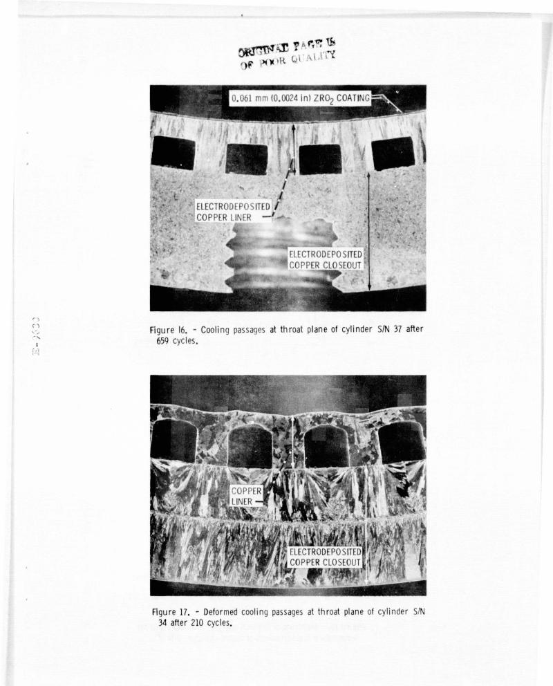
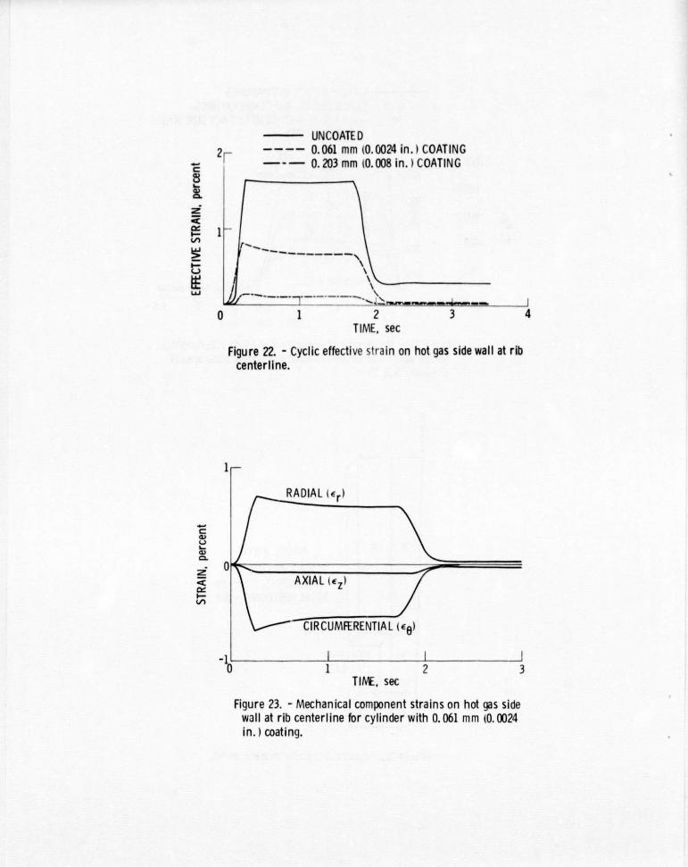
FI ure 22 sit wS LlIl' cyclic I'f I"tive stntin on ell h t-glls-side wall ..It the rih centerl!n ' as a fun tion (c ' Ie tlme. Th mux!mqm elfl'ctive str.:lin oc urred at thIs loca ti n or l'dt'lt at the thn',' cyllnd rs. It c an b' s ...... n thJt the maximum l't(ecltve strain tlH each c -Limll'r oc urn'd at <IPplu~lUlJtLt· 0.3 s"~)nJ .;J ter ir.nilf p dill int:'u as zero on lhl tim~ scu tt.). Till' minimum t.'ifC'ctivc strain occurred Dt appraxim~t 'Iy 2.2 s('c nds lifter ignition (or till' unC1Hlt'd . linder and Lhl' e linder with the O.Oul mm (0.002[, in.) coating ..tnd nt approximately ,.0 51' onds alter ignition tor the cylind r with the 0.20 nun (0.008 in.) coat ng. Th's werl' thl' imes when the m.l xlmUIIl tl'mp «ttur" dlff'r-
n I' b'tw' n he hot-~as-side me tdl wall and t he backs id" WD 11 OC U rred . The mdX imum 'f t et' ti ve strain for the ylindl't' with 11' 0.0 I IttItI (0.002 in . ) C Dtlng W,lS approximately nnl'-halL that 01 the un <lated ylimtl'r .Ind th e mdximlUtt ' ,'ctlve strain lor thl' c lind'r ,dth the 0 . _03 !1111 (0.00 in.)
ntln. w S ilppr ximDtely one -twl' l fth that (the uncoat d cy lind ' r. TIli, o[ cou rse, was attributed
the I w r hot- s-tiide m III w II t mp'r tur hat the oatin pr vided.
lIll'chan the 0.0 L \TID
tr<lin entia 1 durin th' entire c ele. of the
reve rs ,11 had be n dd'd .
Fi -l\r~ 2 haws the e fective st rain r nge dis tribution th" throat pl n~ lor the thr ' yl-inders. Th~ max imum s r a in r n 0 cu rred n the h t- as- side all at th~ rib cl'nte rlin r the un-coa ted lind r and the cy linder with th e 0.0 1 mm (0.002 in.) , ting .md on th h t- -sid wall aL the coolin pasaag" centerline f r with th~ 0 . 203 nun (0.00 in .) ma imum strain I·,mges and th m ... t rial life cu rve o tiMur' 2S tak n [rom reference I ,th theor'ti-al lives of the unco ted cylind~r and the cylindl'r
with tht' 0.0 1 mm (0.002' in , ) 'oatin ' wer found t he 300 c eles and 1 00 cy les, r~p tively. Becdu I' 0 1 th .. small strDin rangP b ained [ r the cyLind,'r with the 0._03 !1111 (0.00 ~, in . ) 'oa tin , It Wolb only p ssible to c nclude from fi ur the the~rltlc31 life [ this cylinder is great r tholn 10 000 cy 11.' 5 .
rhe 0 . 203 !1111 (0 . 00 in .) c atin' , alth ugh a ver e fecLive th nnal barrier, Dppeored t be too thi ck as evidenced by the 'roston that t k plae durin - the cyeli' testing. The a t that th e e r oded 'oo tin' thickn ss stubili cd at 0.061 IlTIt (0 .002 in.) sugg ts that if the COOLing had been that thickn ss initially P !lsihL n rosion VI uld Iwvc taken pinel'. 1I0wevl'r, It the pres nt tim, ther is n ~videnee to substantia t e th is . AL-though erosi n [the coa tin urred, th remain-in' coating WilS w Ll adh~r'd. lectroform-in a m'tal wall to pears to pr vid' better tion I m~thod of asmothwo ll.
c nvencoating a nt
Due La the profound reduc ti n in e(lec t iv s train and th a camp nyin' lor p tential in-er'ase in IUl' that can be a 'hieved by usc III ce-rami c a ings, th~ [urth,'r dev I pment t,1 rellabl oatin' s stl'ms (or r eket thrust chamber opplicu
tion "ppears t be 0 worthwhile endeavor.
Surranary of R su Its
1'w cy lindrical r cke t t hrust chomb'r evlindl'rs were coated with 0.203 IlTIt (0.00 in. ) of zi r onium- xid and 'yclica I tested t sh w Llll' [tect III th e coating on thrust homb r life. Th,'
tesLS wcr' ondu ted ..It a n minal hamb'r pressllr . 1 HN/m2 (00 ps i ) u in hydro n-oxy'en
pr pI.' Llants t an xid nt-[u I ratio at . 0. 1111'

cylinders w re cooled with liquid hydro' n at an average flow r t ot 1. 0 kg/s c (2.2 lbm/ c ). Although n tth r of th coated cylinders chieved their th ort'tical expected liv ,due t o c us S un-related to the co ting syst m, th ollowing r -sults w re obt in 'd:
1. On coated cylinder endured 65 thermal cycles , despite a blocked coolin passag, as compared with 210 cycles for an unco led cylind r tested at the sam conditl ons .
2 . In the regions of the cylinders where th coating eroded, the original 0.203 mm (0.008 in. ) coating er ded to a sLabilized thickn ss of 0.061 mm (0.0024 in.) in the first 80 cycles .
3. Ex luding the local burnout area on one cylinder, there was no oth'r ar a on either cylind r whe re the copper wall w ~ xposed du Lo failure of th coating to adher .
4 . The coatin s had a significant ef ect on suppressing the characteristic cooling passage wall deformation and thinning observed on previously tesLed uncoated cylinde r s.
5. rhe calculated hot-gas-sid metal wall temperature, th hot - gas-side to backside metal wall temperature difference, and the heat flux wer reduced approximately 80 percent where the coating was 0.203 mm (0.008 in.) thick and 0 percent wher the coa ting was 0.061 mm (0 .002 in .) thi ck when compared to the uncoated cylinder .
6. Th 0.203 mm (0 . 008 in.) coating and the r emaining 0.061 mm (0 . 002 in . ) oating r duced the theor ti al maximum effective strain in the cooli ng passage wall to one -twelfth and one-half that of the uncoated cylinde r, respec tively .
7. The reduced sLrains showed th theore tical lives of coated cylinders to b g r ea ter than 10 000 cycl s for a stabl 0.203 mm (0.008 in .) coa ting and 1900 cycl s for a stable 0.061 mm (0.0024 in.) coating , compared to a predicled 300 cycle Ii e for an uncoated cylind r .
Referenc's
1. Quentmeyer , R. J., "Experimental F.ltigue Life Investigation of Cylindri.:al ThrusL Chambers," AIAA Paper 77 - 893 , July 1977.
2. Hannum, N. P ., Kasper , H. J ., and Pavli , A. J., "Experim ntal and Th orctical Investigation of Fatigue Life in R uSi.lble RockeL Thrust Chambers," AIM Paper 76-685, July l7b.
3. Fulton, D., "Investigation of Thermal Fatigue in Non- Tubular Regeneratively Cooled Thrus L Chamh rs, Volume 2," Ruckwc·ll InLernat:ional Corp. , Canoga Park , Calif., R-9093-V 1-2, Nay 1973 (AD-760583; AFRPL-TR-73-10-Vol-2).
Price , H. G. , Jr. , Schacht , R. L., anJ Quent-m yer, R. J., "Reliability and Effe tive Thermal ConductiviLy of Three Metallic-Ceramic Composit Insulating Coatings on Cooled Hydrogen-Oxygen Rockets," NASA T D-7392, 1973.
7
5. Schacht , R. L., Pric , H. G., Jr ., and QUl'nt-m yer, R. J., "Eff ctiv ThermJl Conductiviti s of Four ~Ietal-Ceramic Composit Coatin '5
in Hydro en-Oxyg n Rock 't Firings," NASA T' 0-7055, 1972.
6. Curr n , A. N., Grisaffe , S. J. , and Wycol , K. C., ''Hydrogen Plasma T sts 01 Som Insulating Coating Systems for the Nu I ' r RuCK t Thrus t Chamber," NASA T I X- I, 1972.
7. Stubbs, V. R., "0 velopm nt of a TIlCrma1 Barrier Coating for Use on a Water-Co01eJ ozzl~
of a Solid Propellant Rocket Motor," A l' Oj~t
Gen ral Co rp., Sacram nlo, CA, lay 3, 19 9. (NASA CR-725 )
Lewis, W. J., "Coatings for R gen rative Engines, " Rep. 28238T-FR-l, Aerojet-Gl'ncral Corp., Sacram nto, CA, July 12, 1968. (NASA CR-72 13)
9. Lewis, W. J., "Coatings for Advanced TIlrUS l Chambers," Aerojet-Gen r al Corp., El HonLe, CA , 1968. (NASA CR-72 0 )
10. Hjelm, L. N., and Bornhorst, B. R., "Devl' lopment of Improv d Ceramic Coatings to Increase th Life 0 f XLR 99 Thrus t Chamber," NASA Ul X- 57072 , 1961 , pp. 227-253.
11. Hamm r, S., and Cza ka, Z. , "Deve l opment 01 Advanced Fabrication Techniques [or R<'g<'!w ratively Cooled Thrust Chambers by the Electroforming Proc ess ," Camin Labs ., In.:., Brooklyn, N.Y., Oct. 1, 1968 . (NASA CR-72698)
12 . Smith , J. P ., "Systems Improved Numerical Dilf r ncing Analyzer (SINDA): Us r's lanllill," TR\O/ Systems Group, R dondo Beach, Calif., TRW- 1 690-HOOl -RO-00, Apr. 1971.
13 . Vos , R. G . , and Straayer, J. \0/., "BOPACE-3D (Boeing Plastic AnalysiS CapabiliLy for 3-Dimensional Solids Using Isoparam tric Finit Elem nts)," Boeing Aerospac Co., Sl'aLtl<', WA, D180- 18677-l, Apr. 1975. (NASA CR-l .J891)
1 . Armstrong, W. II., and Beogren, E . ., "3-D Thrust Chamb r Lif Prediction," BOl' ing A~rospace Co., Seattle, \,/A, Mar . 1976. (NASA CR- 13 979)
15. Esposito, J. J., and Zabora, R. F., "Thrust Chamber Life Prediction. Volume I: Medwnical and Physical Prop rties of 1Iigh P,'r[orma nce Rocket ozz Ie Materials," Boeing A<'rospace C . , Seattle , WA, D180-18b7]-1-Vol-l, Mar . 1975. (NASA CR-l3 80b)
16. Conway, J. B., Sten Lz, R. H., and Berlin, J T . , "High Temp ratun' , Low-Cycle Fat igue of Copper-Base Alloys in Argon. Part 1: Preliminary R suIts for 12 Alloys at 10000 F ( 5380 C) ," Mar-Test Inc., Cincin,la-j, OB, Jan. 1973. (NASA CR- 121259)

rAI'LE 1. - C'lLlNDER CONF1GUMTl S AND TEST RE ULTS
Cy1 Lnde r S N '<ln lL 'u r t l ~)n T' t ·c l~s R mar 5
8 . t !)"lil t ed 210 T 'p t eal loilu re, ra ck in e llli n ' passage \.loll in thro t re 10n
Zn)~ ,'Oll l in' 0 L'nrcpLl i rab 1 ' e ra k in m ni old ,,'e ld 5e m ne r i njee t o l' , t 'S Un!; t n11ino ed
i ZrO, t.:l."I • .l t 1 l'll'!. 5 Bu r n ut in throa t r i o n due t o - bl ock d c oling oaSSB' e
.. lR,,-,sult~ tJ k~n t ro. r~i. t.
Tt U' T1. - RESl'LTS 0F THF R.'IAL A;,AL\'S I
I ... ",'I ho t- ~n S-~'d. c Cl.'a ll n~ t,"'mp~ r atu r e~ Trm..,., h t- g s -sLd me lal \.Ia 1 t t mpe r .l t u r e. r , h, t- :.!~ - ide ,nL' t ell "'all (0 b.lL:'·sid ,,'all tempe rat u r di [ ren q, hea t 11u~.
Cyl inder S ~ {1.'Jtin ... i!\," .. ' T , q th . cknl... ... s (OR) (O R)
, , K K \ R) ~C\ m~
':':'1 \ In.) (Btu in2 / 5
3~ ------------- ------- - --- .. (1520) ss 1000) 57 .2 (35)
i O . ~O \0 .00:') 2 22 \52 0) 57 (2 2) 0 ( l b2) 1 (7.3)
r 0.0(" \l1. 002 ) 1 - (J (0) 6 \.:1 0) 322 ( 0) .. (21 )
c)

ANNULAR INJECTOR -
/ /
I MANIFOLD AND / INJECTOR BODY
WATER COOLED CENTERBODY -,
/ /
ANNULAR LH2 IN / THROAT .. / REGION \ /
\ \001&'- / / --r------1 ..
4.06 cm 6.60 cm (1.6 in) (2.6 in)
--- - 4- H20 OUT
/ L LIQUID HYDROGEN
COOLED CYLINDER
..
Figure 1. - Schematic of cylindrical thrust chamber assembly.
•

7. ADD ELECTROFORMED COP PER CLOSEOUT
6. FI LL COOLANT PASSAGES WITH WAX
8. REMOVE WAX
5. MILL COOLANT PASSAGES
1. S. S. MANDREL
2. ADD Zr-02 LA YER
3. ADD NICHROME LAYER
4. ADD ELECTROFORMED COPPER LAYER
Figure 2. - Fabrication sequence for coated cylinders .

TYPICAL RIB THERiVO COUPLE HOLE "\
\
,
"-'-D. ll} em
(0.051 in .)
0.0203 em (0. OO! in. ) NICHROME -Zr02 COATING
'-- 0.089 em
\
"- (0.035 in) '-- 0.169 em
(0.0665 in)
, \
, I
ELECTRODEPOS ITfD COPPER CLOSEOUT 7
THERMA L AND / STRUCTURAL / MODEL "" /
\
/ /
'- 72 COOLf NG I CHANNELS
7\ L ELECTRODEPOS!TED
COPPER UNER
\ '-- 3. 302 em R
(1.3 in)
Figure 3. - Cylinder wall cross section showing instrumentation locations and dimensions.
)f{l<';l~ L l\ '~F.' fS! . I'() )1" I I Lr:'Y1

C-76-3977
Figure 4. - Coated cylinder SIN 37 with instrumentation installed.

I
~1
Figure 5. - Annular injector.
OR.'~ G t , ,: : r I Ih j ~ l " L

WATER INLET
C-77-832
Figure 6. - Ceramic coated, water cooled centerbody for cylindrical thrust chamber.
~ ..
,J
r--+
" 1
.. ' ,:,
LI THR UST, STRAIN-GAUGE-BRIDGE TYPE LOAD-CElL
FI } OXIDIZER FLOW, TURBINE TYPEFLOW METERS FZ
PI } COMBUSTION CHAMBER PRESSURE. STRAIN-GAUGE-BRIDGE TYPE PRESSURE TRANSDUCER Pz p) OXIDIZER I~ECTION PRESSURE.
P4 FUEL INJECTION PRESSURE.
P5 FUEL ORIFICE PRESSURE
P6 COOLANT OUTLET PRESSURE.
P7 COOLANT INLET PRESSURE ,
Pa COOLANT TANK PRESSURE.
P9 WMER TANK PRESSURE.
VENT
() GHe PRESSURANT
..
"' / "l"'" - I.)"'"
TI OXIDIZER TEMPERATURE AT FLOWMETERS, PLATINUM RESISTANCE BR IDGE TRANSDUCER
TZ OXIDIZER I~ECTION TEMPERATURE. PLATINUM RESISTANCE BRIDGE TRANSDUCER
T) FUEL TEMPERA TURE AT OR IF ICE. COPPER iCONSTANTAN THERt.'OCOU PL&
T4 COOLANT TEMPERATURE AT VENTUR I, PLATINUM RESISTANCE BRIDGE TRANSDUCER
T5 COOLANT OUTLET TEMPERATURE. CHRON£VCO/oiSTANTAN THERt.'OCOUPLE
T6 COOLANT IM.ET TEMPERATURE, PLATINUM RESISTANCE BRIDGETRANSDUCER
DPI OXIDIZER I~ECTOR PRESSURE DROP, STRAIN-GAUGE-BRIDGE TYPE PRESSURE TRANSDUCER
DPZ FUEL I~ECTOR PRESSURE DROP,
DP) FUEL ORIFICE PRESSURE DROP,
DP 4 COOLANT JACKET PRESSURE DROP,
DP5 COOLANT VENTUR I PRESSURE DROP,
DP6 WATER VENTUR I PRESSURE DROP,
BURN STACK VENT VENT
HzO COOLANT
LOZ
LNz
n GHz
STORAGE
GHz FUEL
-V
COMBusnON GASES INTO SCRUBBER
+
GHZ
PRESSUR ANT
+ Figu re 7. - Schematic 01 test faci lily,
V[NTURI ~ __
\- VACUUM JACKET GNZ PRESSURANT ..
GNZ STORAGE

2. ,...CH AMBER PRES- 5 /
4 I SURE, Pc r LiQUID
" HYDRO~N 4 600 I WEIGH
3 I U I FLOW, W H 3E u ~l. I
Q)
Z 400 VI C'I
£ ~
~ .~ 2 ~ VI
c. N 3 .8 2 u 3 Q.. U 3: Q.. 3: 200 1 .4 1
0 0 0 0 .8 1.6 2.4 3.2 4.0
Tlw{, sec
Figu re 8. - Computer plot of chamber and liquid hy-drogen weight flow for a typica I cycle.

) ) ., "'
()R.J IN .~ PAGE' 1& 0' POOR QU ALrN
Figure 9. - Cylindrical thrust chamber during cyclic test.

THROAT PLANE -. ••• •••••• " "
. • \
. "" C-78-1093
Figure 10. - Non-eroded coating in th e throat region of cylinder SiN 36.
. .. I I
•
• . .
' ..
C-78-1094
Figu re 11. - Eroded coati ng in the th roat region of cyli nder SIN 36.

ORJGINAL PAr.P,' I or R Ql LlTY
Fi gure 12. - Burned out cooling passage in throat region of cylinder SIN 37.
Figure 13. - Blocked cooling passage of cylinder SIN 37.

THROAT PLANE ""\ \
• C-78-1335
Figure 14. - Uniformly eroded coating surface of cy linder SIN 37.
0:: o
800 400
600 ~o ~ 300 0>0
00 ooCb 000610
....: 0 '400 ....: 200 0
200 o
100 L---L---L---~ __ ~ __ ~ __ ~ ___ o 100 200 300 400 500 600 700
CYCLES
Figure 15. - Steady-state temperature of a rib thermocouple in an eroded region of coated cylinder SIN 37 .
, , r)
I [-1
Figure 16. - Cooli ng passages at throat plane of cylinder SIN 37 after 659 cycles.
Fi gu re 17. - Deformed coo ling passages at throat plane of cy linde r SIN 34 after 210 cycles.

~ ...:
1600
1400
1200
1
400
200
o
400
300
200
100
0
-- CALCULATED TEMPERATURES o 0
<>
300
200
100
AVERAGED EXPERIMENTAL RIB TEMPERATURES A~RAGED EXPERIMENTAL BACKSIOC WALL
TEMPERATURES
r HOT-GAS-SIDE \
\ METAL WALL, Tgw T.e. \ \ BACKSIDE.,
\ I
STEADY-STATE HOTGAS -SIDE METAL WALL
\
\... T gw
o . 5 1. 0 1. 5 2. 0 2. 5 3. 0 3. 5 TINt:, sec
Figure 18. - Matching of thermal analysis with experimental temperature measurements of uncoated cylinder SIN 34.
~
I-
--- CALCULATED TEMPERATURES o 0 A~RA(ID EXPERIMENT AL RIB
TEMPERATURES
200
150
100
50
0
<> AVERA(ID BACKSIDE WALL TEMPERATURES
r HOT-GAS-SIDE METAL WALL, T mw : r RIBATT.C.l , ,
I , ,
r RIB ATT. C. 2 "
LBACKSIDE WALL
. 5 l. 0 1. 5 2. 0 2. 5 3. 0 3. 5 Tlwt, sec
Figure 19. - Matching of thermal analysis with experimental temperature measurements of coated cylinder SIN 37.

I
I!
0:: o
....:
1000
800
600
400
--- CALCULATED TEMPERATURES
500
400
~300 .... :
o 0 EXPERIMENTAL RIB TEMPERATURES o AVERACl:D EXPERIMENTAL BACKSIDE WALL
TEMPERATURES
r HOT-GAS-SIOC " METAL WAL Tmw
200 100
o L--L_---'-_----''--_-'--_-'--_-'-_--' o . 5 1. 0 1. 5 2.0 2.5 3. 0 3. 5
TIME, sec
Figure 20. - Matching of thermal analysis with experi mental temperatu re measu rements for the eroded coating area of cyli nder SIN 37.
R
t
8 9
1\ 7
5 6 3 4 1 2
"- '\.
j'I
TO TO TO
'\ COOLANT PASSAGE
['. ['\ r\
"
MODEL 3-D (9)
TAL ElEMENTS " 9 TAL NODES 95 TAL FREEDOMS " 285
a
Figure 21. - Bopace 3-D finite element model.
-c: 8 ~
8.
-c: cu u ~ cu c.
1
o
1
r-_
UNCOATED ---- 0.061 mm (0.0024 in.) COATING -- - 0.203 mm (0.008 in.) COATING
----------, \ , \'--------
-- --------., \ ,
1 2 TIME. sec
3
Figure 22. - Cyclic effective strain on hot gas side wall at rib centerline.
CIRCUMFERENTIAL (Ee)
-~~--------~1----------~2----------~3
Tift(. sec
Figure 23. - Mechanical component strains on hot gas side wall at rib centerline for cylinder with 0.061 mm (0.0024 in. ) coating.
4

0.061 mm (0.0024 in . ) COATING
UNCOATED
0. 203 mm (0.008 in. ) COATING
Figu re ~. - Effecti~ strain range distribution (percent) at cylinder th roat plane for three cylinders.
.>- - / 0 3 :
c Q) u ~
8-
~ z ~ 0::
~ oCt: 0:: ~ V')
10
100
-- WROUGH ANNEALED OFHC COPPER -- E. F. COPPER
1. TEMPERATURE RANG: OF 290 TO 810 K (52?> TO 145sO Rl.
2. ALL ENVIRONMENTS . 3. EFFECTIVE OR UNIAXIAL STRAIN RANCIS .
--~ I ----+ --- ---
I I I I I I I I I I I
I----'----r-~----- I 10-1 I I I I I I I I • I I I I I I I
1~ 1~ 1~ CYCLES TO FRA CTURE
Figure 25. - Typical low-cycle fatigue life of wrought annealed OFHC copper and electroformed copper (E. F. CuI.