INVESTIGATION OF TEMPERATURE PROLIFE IN THE WAVEGUIDE...
22
INVESTIGATION OF TEMPERATURE PROLIFE IN THE WAVEGUIDE SHAFINI MOHD. SHAFIE A project report submitted in partial fulfilment of the requirements for the award of the degree of Master of Electrical-Electronic& Telecommunications Faculty of Electrical Engineering Universiti Teknologi Malaysia May 2006 4
-
Upload
vuongduong -
Category
Documents
-
view
214 -
download
0
Transcript of INVESTIGATION OF TEMPERATURE PROLIFE IN THE WAVEGUIDE...

INVESTIGATION OF TEMPERATURE PROLIFE IN THE WAVEGUIDE
SHAFINI MOHD. SHAFIE
A project report submitted in partial fulfilment of the requirements for the award of
the degree of
Master of Electrical-Electronic& Telecommunications
Faculty of Electrical Engineering
Universiti Teknologi Malaysia
May 2006
4

ACKNOWLEDGEMENT
I would like to thank my family, especially my dad for providing wisdom,
encouragement and support in good times and bad. No matter what, they have been
to keep me focused and on the path to success. I would not be where I am today
without their love. I must also thank my supervisor, Assoc. Prof. Dr. Abu Sahmah
bin Mohd Supa’at for his patience, advice and expertise. His mentorship style,
guiding rather than leading, has allowed me to strengthen my intellectual wings and
tackle problems on my own. When I needed it, he was always ready with a helpful
suggestion as well explanation. To all my friends thank a lot for all supporting.
7

ABSTRACT
The demand for data traffic has initiated the development of optical telecommunications. Due to explosive growth of optical network, has brought forward an increased need for guided-wave optical component. The purpose of this work is to investigate the temperature profile in the thermo-optic waveguide. Here, we use one and two dimensional model to analyze the thermal model. We focus on polymer waveguide since these technology is attractive for many advantages, including large thermo-optic coefficient (for Polyurethane (PUR): dn/dt ~ -3.3-4 K-1) and low thermal conductivity ( ~ 0.19 W m-1 K-1). The buried and rib waveguide structure is used for two dimensional model thermal analysis. We interested to see how heating the heater will change the refractive index and change the profile in the waveguide. Thermal coupling became next task of this project. We analyze the effect of heater to the nearby waveguide. To perform this analysis, we utilized a commercial finite element method (FEMLAB 2.0), which is a tool for PDE-based multiphysics modelling in an interactive environment-MATLAB. The simulated result will use one and two dimensional model respectively. Effective index change is dependency of heater size as well as distance between core to the heater. Increasing 1µm of heater width will reduce -0.1 of dneff/dt it also increasing the power consumption. Thermal coupling is related to waveguide spacing and depth. The coupling estimation is increase with the waveguide depth but decrease with the waveguide spacing. Apply trench structure can reduce the thermal coupling estimation, K .The temperature of heated waveguide decreases as the trench depth increases, therefore it requires less power in performing its function.
8
ABSTRAK
Perkembangan terhadap komunikasi optik bermula dengan permintaan terhadap pengangkutan data. Peningkatan yang cepat memberi peluang terhadap penggunaan komponen gelombang pandu. Matlamat di sini adalah untuk mencari kesan suhu terhadap gelombang yang di panaskan. Oleh itu, penggunaan satu dan dua dimensi digunakan didalam analisis kesan haba ini. Analisis ini dilakukan menggunakan bahan polimer kerana ia mempunyai pemalar haba optik yang tinggi( dn/dt ~ -3.3-4 K-1) dan juga pengaliran arus elektrik yang rendah ( ~ 0.19 W m-1 K-1). Model haba menggunakan dua bentuk struktur gelombang yang berbeza iaitu penanaman (buried) dan juga melengkung (rib). Kami ingin melihat bagaimana haba memberi impak terhadap perubahan indek bias dan juga terhadap profil gelombang. Selepas itu, fokus terhadap perangkai haba (thermal coupling) di lakukan. Analisis pemanas terhadap gelombang yang bersebelahan dilakukan. Untuk melakukan semua analisis ini kami menggunakan komersial perisian iaitu FEMLAB 2.0 yang mana menggunakan asas fenomena fizik model dan juga persamaan matematik. Ia juga interaktif dengan perisian MATLAB. Simulasi akan menggunakan satu dan dua dimensi. Perubahan indek bias bergantung kepada saiz pemanas dan juga jarak di antara teras (core) kepada pemanas. Peningkatan sebanyak 1µm kelebaran pemanas akan mengurangkan -0.1 perubahan indek bias (dneff/dt) dan ini akan meningkatkan penggunaan kuasa. Manakala, perangkai haba (thermal coupling) amat bergantung kepada jarak di antara dua gelombang dan juga kedalaman teras. Nilai ini, K akan meningkat bergantung kepada jarak kedalaman gelombang dan mengurang sekiranya jarak di antara dua gelombang meningkat. Penggunaan kaedah perparitan (trench) akan mengurangkan nilai perangkai haba,K. Suhu gelombang yang di panaskan akan berkurang sekiranya kedalam parit (trench depth) meningkat. Oleh itu, ia akan menjimatkan penggunaan kuasa di dalam melakukan sesuatu fungsi.
9

LIST OF CONTENTS
CHAPTER TITLE PAGE
DECLARATION ii
DEDICATION iii
ACKNOWLEDGEMENT iv
ABSTRACT v
ABSTRAK vi
TABLE OF CONTENTS vii
LIST OF TABLES x
LIST OF FIGURES xi
LIST OF SYMBOLS xiv
1 INTRODUCTION 1
1.1 Statement of the Problem 2
1.2 Integrated Optics in Polymers 3
1.3 Scope of this Work 5
1.4 Overview of this Report 6
2 THERMAL WAVEGUIDE ANALYSIS 7
2.1 A Brief History of Integrated Optic 7
2.2 Literature Review 9
2.2.1 Thermal Analysis 12
2.2.2 Thermal Coupling 13
10

3 OPTICAL WAVEGUIDE 14
3.1 Optical Waveguide Theory 14
3.1.1 Wave vector and propagation constant 15
3.1.2 Maxwell Equation 16
3.1.3 Wave Equation 17
3.2 Structure Waveguide Concepts 19
3.2.1 Rib waveguide 21
3.2.2 Buried waveguide 21
3.3 Waveguide Control 22
3.4 Polymer Waveguide 23
3.4.1 Material thermal properties 24
4 MODELING AND DESIGN OF WAVEGUIDE 26
4.1 Finite Element Method 26
4.2 Heat Transfer Equation 30
4.2.1 One dimensional model 31
4.2.2 Two-dimensional model 32
4.3 Thermal Model 33
4.4 Simulation Guide 35
4.4.1 Setting the model in FEMLAB 35
4.4.2 Option and Settings 37
4.4.3 Draw mode 39
4.4.4 Boundary Mode 40
4.4.5 Sub domain mode 41
4.4.6 Mesh Mode 42
5 RESULTS 44
5.1 Thermal Analysis 45
5.1.1 Two Dimensional 46
5.1.1.1 Rib Waveguide Structure 46
5.1.1.2 Buried Waveguide Structure 49
5.1.2 One Dimensional 54
5.2 Thermal Coupling 55
11

6 DISCUSSION 61
6.1 Thermal Analysis 61
6.1.1 Rib waveguide structure 62
6.1.2 Buried waveguide structure 65
6.2 Thermal Coupling 69
6.2.1 Original waveguide structure 69
6.2.2 Trench structure 71
7 CONCLUSION & RECOMMENDATION 78
7.1 Thermal Analysis Model 78
7.2 Thermal Coupling Model 79
7.3 Future directions 80
REFERENCES 74
12

LIST OF TABLES
TABLE NO. TITLE PAGE
1.1 Integrated optics market in 2001 by material type 2
1.2 Typical properties of waveguides in popular materials 4
used in integrated optic.
5.1 Opto-thermal parameters for utilized materials 44
5.2 Two types (A-B) of waveguide structure, shown together with
response times. 52
6.1 Waveguide Geometric Dimension 63
6.2 Thermo-optic coefficient, dneff/dT dependent on heater width. 68
6.3 Calculated Power for various trench depth structure 77
13

LIST OF FIGURES
FIGURE NO. TITLE PAGE
2.1 Integration and cost reduction roadmap for 10
organic-inorganic hybrid integration platform.
2.2 Thermal distribution at heater temperature of 100°C and
(b) effective refractive index change versus heater temperature
for various distance H of the heater in structures of series 1. 12
3.1 Vector triangle describing the relationship between β, к and k. 15
3.2 Illustration of typical rib waveguide geometry and reference 17
coordinate geometry.
3.3 Simple waveguide structure 18
3.4 Typical dielectric waveguides 20
3.5 Schematic concept for control of guided modes. 22
4.1 (a) Finite different and (b) finite element method discretizations
geometry. 27
4.2 Divided the region (a) the rib waveguide is divided into sub-
domain region, which are triangles and (b) one dimensional is
divided into finite number of element. 28
4.3 Geometry of (a) cross section of rib waveguide with heater on
top of ridge and (b) buried waveguide structure used for
coupling analysis. 34
5.1 Schematic diagrams of the (a) rib and (b) buried waveguide
structure cross section. 45
5.2 2D thermal distribution with W= 1µm and H=0.5µm. 46
5.3 2D thermal model rib waveguide structure with H=0.2µm and
14

heater temperature 300K. 47
5.4 Contour plot of heat lateral (a) heater width 20µm and (b) heater
width 10µm.The heater temperature apply is 350K. 48
5.5 Temperature distributions for buried waveguide structure with
core dimension 8µm×8µm at heater temperature 100K. 49
5.6 Temperature distributions for buried waveguide structure with
core dimension 6µm×6µm at heater temperature 100K. 50
5.7 Heat distributions for buried waveguide structure with
8µm×8µm at heater temperature 350K with different distance. 51
5.8 Calculated temperature distribution in (a) rib waveguide
structure (type B), and (b) a buried waveguide structure (type A). 53
5.9 1D thermal distribution with W= 0.5µm and H=1µm. 54
5.10 The cross section of a thermo-optic waveguide (a) original
waveguide with heater on top and (b) trench structure. 56
5.11 The temperature distribution of the original waveguide where
the waveguide dimension is 8µm× 8µm. 57
5.12 The temperature distribution of the trench waveguide. 58
5.13 Temperature distribution where (a) trench depth, h is 3µm and
trench width 2µm, (b) trench depth, h is 13µm and trench width
2µm, (c) trench depth, h 4µm and trench width 2µm and
(d) trench depth, h 4µm and trench width 1µm. 60
6.1 Effective index change versus heater temperature for various
distance H of the heater. 62
6.2 Thermo-optic coefficient dneff/dt and switching power versus
the waveguide rib width. 64
6.3 Core waveguide temperatures in the function of waveguide size. 65
6.4 Effective index change versus heater temperature for various
distance H of the heater. 67
6.5 Effective index change in the function of heater width with
H=7µm and core size 8µm× 8µm. 68
6.6 Coupling estimation, K versus spacing for original structure in the
function of waveguide depth, h. 70
15

6.7 Coupling estimation, K versus spacing for trench structure in the
function of waveguide depth, h. 71
6.8 Comparison between the original and trench structure (a) coupling
estimation and (b) effective index change different waveguide 1
and waveguide 2. 73
6.9 The relationship between (a) the K and (b) effective index
different versus trench depth when waveguide spacing is 4µm. 75
6.10 The temperature rise of the heat waveguide and trench depth with
varies the waveguide depth. 77
16

LIST OF SYMBOLS
A - contact area
C - heat capacity
d - trench depth
d - distance of heat flow
K - thermal coupling estimation
k - thermal conductivity
H - distance from heater to waveguide core
h - waveguide depth
L - heater lenght
n - refractive index
Q - rate of heat flow
s - waveguide spacing
t - thickness of the polymer bottom layer
W - heater width
β - propagation constant
ε - relative permittivity
µ - relative permeability
∆ - temperature ratio different
Φ - change in polarizability with temperature
ρ - density capacity
λ - wavelength
γ - coefficient of volume expansion
17
CHAPTER 1
INTRODUCTION
Guided wave optics will play an increasing and important role in optical
communication networks and optical sensor systems. In particular, polymeric
waveguide devices are being developed; because the process can be low-cost, and
high manufacturing output can be achieved. The low temperature fabrication process
of polymer waveguide also gives the designer a large degree of freedom. Because
most polymer materials have a thermo-optic coefficient an order of magnitude larger
than that of silica, thus, they can be temperature tuned over a wider spectral range
(Edwin Y. B. Pun and W.H. Wong, 2002).
In general polymer has a temperature dependent refractive index which is
known as the thermo optic (TO) effect. Recently, the active optical glass waveguide
utilizing the TO effect such as modulators and switches has been demonstrated
(M.Haruna and J.Koyama ,1982). In 1989, there is published paper due to application
of TO which is using polymer waveguide to make a switch. The author demonstrated
that effective index changes at least one order higher than those obtained with the
electro optic effect in LiNbO3 are found (M.B.J. Diemeer, J.J. Brons and E.S.
Trommel, 1989). Two years ago, the researcher (H.P. Chan, C.K. Chow and Alok K.
Das 4, 2003), found that by using the polymer material in application of digital
optical switch (DOS), there can reduces the crosstalk value.
18
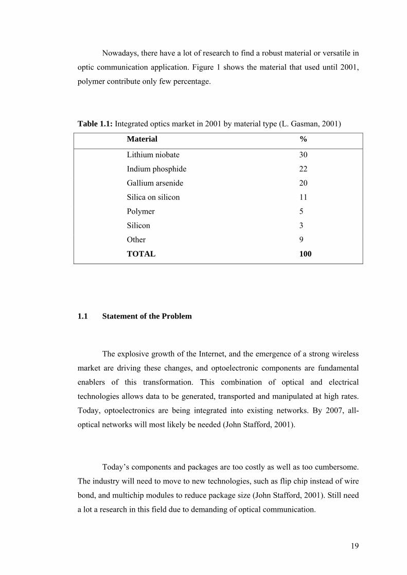
Nowadays, there have a lot of research to find a robust material or versatile in
optic communication application. Figure 1 shows the material that used until 2001,
polymer contribute only few percentage.
Table 1.1: Integrated optics market in 2001 by material type (L. Gasman, 2001)
Material %
Lithium niobate 30
Indium phosphide 22
Gallium arsenide 20
Silica on silicon 11
Polymer 5
Silicon 3
Other 9
TOTAL 100
1.1 Statement of the Problem
The explosive growth of the Internet, and the emergence of a strong wireless
market are driving these changes, and optoelectronic components are fundamental
enablers of this transformation. This combination of optical and electrical
technologies allows data to be generated, transported and manipulated at high rates.
Today, optoelectronics are being integrated into existing networks. By 2007, all-
optical networks will most likely be needed (John Stafford, 2001).
Today’s components and packages are too costly as well as too cumbersome.
The industry will need to move to new technologies, such as flip chip instead of wire
bond, and multichip modules to reduce package size (John Stafford, 2001). Still need
a lot a research in this field due to demanding of optical communication.
19
As the new technology trends to increase the speed and the bandwidth for
communications in wide area networks, the all optical network becomes a good
choice as a solution for that problem. New devices and materials using linear or non
linear effects of light are extremely useful for such networks because of their
compatible speed (Mario L and Jose A.M. Pereira, 1996). Our project use polymer
material to build optical waveguide. Recently, development on optical polymer
waveguide will used electro –optic to implement the device. Because polymer has
large TO coefficient, we will apply this effect to implement future device.
1.2 Integrated Optics in Polymers
Polymer materials are of great interest in integrated optics as they can be
tailored to meet specific applications. The thermo-optic effect is large in these
materials -1×10⁻⁴ K-1 to -4×10⁻⁴ K-1 which leads to power efficient dynamic
components. They are potentially low cost and rapidly processed by direct photo
patterning or reactive ion etching. Waveguide can be designed with very large or
very small index contrast between core and cladding (0% – 35%). Polymer can also
have very low optical loss <0.1dB/cm at the telecommunication wavelengths 1310
nm and 1550 nm (John M. Senior, 1992). Cross linked polymer systems operated
above the glass transition temperature even allow for waveguides free of stress
induced scattering and birefringence. Polymer material classes used in integrated
optics include acrylates, polyimides, polycarbonates and olefins (Robert Blum,
2003).
Realized polymer devices cover a wide range of optical applications like
switches, couplers, filters, attenuators, polarization controllers, dispersion
compensators, modulator, laser and amplifiers (R.T. Chan,1993).Even 3D multi layer
architectures of integrated circuits are possible as successive layers are deposited b
simple spin coating (S.M. Garner et all, 1999).Table 2 compares several typical
20

materials used in integrated optics. In almost all categories polymers exhibit
excellent values. However, it is difficult to combine all these properties in single
material.
Table1.2: Typical properties of waveguides in popular materials used in integrated
optics. The refractive indices of the core and cladding materials are denoted by ncor
and nclad respectively.
Propagation
Loss
[dB/cm]
Refractive
Index
Index
Contrast
(ncornclad)/ncor
Birefringence T/O
Coef.dn/dt
[K-1]
Max.
Modulation
Freq.
Silica 0.1 1.5 0-1.5% 10-4-10-2 10-5 1kHz (TO)
Silicon 0.1 3.5 70% 10-4-10-2 1.8×10⁻⁴ 1kHz (TO)
Polymers 0.1 1.3-1.7 0-35% 10-6-10-2 -1×10⁻⁴- -
4×10⁻⁴
1kHz (TO)
Lithium
Niobate
0.5 2.2 0-0.5% 10-2-10-1 10-5 40GHz
(EO)
Indium
Phospide
3 3.1 0-3% 10-3 0.8×10⁻⁴ 40GHz
(EO)
Gallium
Arsenide
0.5 3.4 0-14% 10-3 2.5×10⁻⁴ 20GHz
(EO)
Most serious problems in connection with polymers are environmental
stability (temperature, humidity) and commercial availability. Thermal aging due to
oxidation is often observed in organic materials as well as water incursion and the
associated optical absorption from the overtone bands of the OH stretch (Robert
Blum, 2003).However, these problems have been solved by many manufacturers
(e.g. AlliedSignal, JDS Uniphase, Du Pont, Dow Chemical) and some materials even
passed the Bellcore 1209 and 1221 test (R, Moosburger et all, 1996).
Unlike silicon, silica or InP, polymers are materials are designed by chemists
to meet specific needs. Their usage is often hindered by patents and they are seldom
sold or manufactured in small quantities as needed for integrated optics (J.D.
Plumber, M.D. Deal and P.B. Griffin, 2000). Therefore commercially available
polymers are usually built for other applications like microelectronics, display or
21

furniture coating. By chance, some of them also show desirable optical
characteristics like BCB (Cyclotene by Dow Chemical).
1.3 Scope of this Work
This project is about an investigation of temperature profile in the thermo-
optic waveguide due to the effect of having thin film heater on top of polymer
waveguide structure by using the one and two dimensional model. Here, we would
like to determine the effective index change from the change of temperature. By
heating the heater, it will distribute the heat in the surrounding area and cause
increasing the temperature in the waveguide structure.
In the way to analyze the TO effect, we will design thermal model based on
two different structure which is rib waveguide structure and buried waveguide
structure. The lateral heat diffusion distance in both structures will be studied. Two
phenomena will be studied seriously, which is the distance from heater to the core
waveguide (H) affect the effective index change. We also interested to investigate
how heater size would affect the key parameters in modelling waveguide structure.
Thermal coupling became an issue when we have two waveguides in parallel.
The structure will consists of two square waveguide. Due to thermal phenomena,
heat one of the waveguide will effects nearby waveguide. Actually, these are
unwanted phenomena and will degrade the devices performance. The relationship
between them is known as thermal coupling estimation. Here, we will determine
these values and try to figure out the way to reduce these effects. One method is by
applying the trench structure. All the simulation is done using software named
FEMLAB. The result can be obtained by GUI (Graphical User Interface). This
software apply finite element as a method to solve all the problems.
22

1.4 Overview of this Report
This section outlines the organization of the work contained in this thesis.
Throughout this thesis we have seven chapters including the conclusion. A brief
history of integrated optic is discussed in Chapter 2. Follow with the literature review
of this project. Several papers are discussed under section 2.2 sub topics.
In Chapter 3, all the theory that applies for the project progress is explained
briefly. The discussion start with phenomena that cause light can travel in the
waveguide. Maxwell equation are introduces to get wave equation. Then, the types of
the structure are discussed following with several type of control waveguide. But for
this project, we focus on thermo-optic control. At the end of this chapter, the
subtopic is on polymer waveguide.
Chapter 4 is about the methodology of the project. Since we used the
numerical method in the way to get the result, a basic theory of finite element
method is discuss. Thermal analysis, which is the heat transfer equation are explain
due to the one and two dimension respectively. Thermal model including rib and
buried waveguide structure is explained under section 4.3. Lastly, a quick step on
simulation used FEMLAB software is shown.
The result section is divided into two sub topic which is thermal model and
thermal coupling. Under thermal model we show the result for rib and buried
structure. One dimensional is also shown under this sub topic. All the parameter that
will be influence the performance of effective index change is shown in this topic.
Discussion and analysis or data interpretation are shown in Chapter 6. A lot of issue
is discussed here. Last chapter is about the conclusion of the project throughout this
course.
23
REFERENCES
Abu Sahmah (2005).Note Optical Communications: Universiti Teknolog Malaysia.
B. A. Moller, L. Jensen, C. Laurent-Lund and C. Thirstrup (1993). Silica-
Waveguide Thermooptic Phase Shifter with Low Power Comsumption and
Low Lateral Heat Diffusion. IEEE. Photonic Tech. Lett. 5(12): 1415-
1993.
C.K. Madsen and Jian H.Zhao (1999).Optical filter design and analysis: Wiley
Interscience.
Cook R.D, Malkus D.S, and Plesha M.E. (1989). Concepts and Applications of Finite
Element Analysis. 3rd Edition: John Wiley and Sons.
D. M. Burland, R.D. Miller and C.A. Walsh (1994). Second- Order Nonlinearity in
Poled-Polymer Systems. Chem. Rev. 94(1):31-75.
Data sheet. OHIDA: Technology Evaluation Report for Optical Interconnections and
Enabling Technologies.
Edwin Y. B. Pun and W.H. Wong (2002).Optical polymeric waveguides and devices;
IEEE, 126-132.
F. Fernandez and Y. Lu (1996).Microwave and optical waveguide analysis by the
Finite Element method. Research Studies Press Ltd.
G N Mercery and R O Weber (1997).Combustion waves in two dimensions and their
one-dimensional approximation. Combust. Theory Modelling 1: 157–165.
H.P. Chan, C.K. Chow and Alok K. Das (2003). A wide- Angle X-Junction
Polymeric Thermo optic Digital Switch With Low Crosstalk. IEEE Photon.
Technol. Lett., 15(9).
Hiroshima Nishihara, Masamitsu Haruna and Toshiaki Suhara (1989).Optical
Integrated Ciucuits:McGraw-Hill Optical and Electro-Optical
Engineering Series.
98
Huihai Yao (2000). Polymer Waveguide based Optical Devices for Optical
Communication. Institude of Telecommunication: Germany.
J. D. Plumber, M.D. Deal and P. B. Griffin (2000). Silicon VLSI Technology. New
York: Prentice Hall.
J. Hecht (2002). Understanding Fiber Optics. 4th Edition: London: Prentice Hall.
John M.Senior (1992). Optical Fiber Communications Principles and Practice.2nd
Edition: Prentice Hall.
John Stafford (2001). Optoelectronic Components Place New Demands on
Packaging and Assembly. Optoelectronics Technology Working Group
for NEMI's 2000 Roadmap.
K. Asatani (1989). J. Lightwave Technol.. 7: 1705.
K. Okamoto (2000). Fundamental Optical Waveguides. San Diego: Academic Press.
D. A. Anderson, J. C. Tannehill and R.H. Pletcher (1984). Computational
Fluid Mechanics and Heat Transfer.Hemisphere, Washington D.C.
L.Eldada (2001). Advances in telecom and datacom optical components. Optical
Engineering. 40.
L. Eldada and L.W. Scahacklette. Advances in Polymer integrated Optics. IEEE J.
Sel. Topics Quant. Electr. 6(1): 54-68.
L. Gasman( 2001). New Materials Renew Life for Integrated Optics. WDM
Solutions:17–20.
M.B.J. Diemeer, J.J. Brons and E.S. Trommel (1989).Polymeric Optical Waveguide
Switch Using the Thermo optic Effect. J. Lightwave Technol..(7): 449-453.
M. Cowin (2001). Telecoms poised to profit from polymer photonics. FiberSystems
International . 2(9): 24-26.
M.Haruna and J.Koyama (1982). Thermo optic deflection and switching in glass.
Appl. Opt..( 21):.3461-3465.
M. Kawachi (1990). Silica waveguides on silicon and their application to integrated-
optic components. Optical and Quantum Electronics. 22:391-416.
M. N. J. Diemer (1998). Polymeric Thermo-optic Space Switch for Optical
Communications. Opt. Materials. 9: 192-200.
M. N. O. Sadiku (1992). Numerical techniques in electromagnetics. CRC Press Inc. M. Stahelin, C.A. Walsh, D. M. Burland, R. D. Miller, R. J. Twieg and W. Volsen
(1993). Orientation Decay in poled second order nonlinear optical guest-host
99

polymers: Temperature dependence and effects of poling geometry. J. Apply
Phys. 73(12): 8471.
Mario L. Lacroix and Jose A. A M. Pereire (1996). Feasibility of optical waveguide
construction using polymers. Optoelectronic:
Mohamed ElShayeb and Yeo Kiam Beng (2000). Applications of Finite Difference
and Finite Element Methods for thermal problems. Malaysia: Universiti
Malaysia Sabah.
P. Sewell, K. Biwojno, S. Sujecki and T.M. Benson (2002). A thermal Model for
Silicon-On-Insulator-Based Waveguide Modulators. IEEE Photonic Tech.
Lett.: 151-154.
R. F. Harrington (2001). Time harmonic electromagnetic fields : Mc-Graw Hill.
R.J. Mears, L. Reekie, I.M. Jauncey and D.N. Payne (1987). Low Noise Erbium-
Doped Fiber Amplifier Operating at 1.54µm. Electr. Lett. 23(19): 1026-1028.
R.L. Espinola, M.C. Tsai, J.T. Yardley, and R.M. Osgood, Jr. (2003).Fast and Low-
Power Thermo-optic Switch on Thin Silicon-on-Insulator. IEEE Photon.
Technol. Lett. 15: 1366-1368.
R. Moosburger, G. Fischbeck, C. Kostrzewa and K. Petermann (1996). Digital
Optical Switch based on oversize polymer rib waveguides. Electronic Letters.
32(6): 544-545.
R. Noe, D. Sandel, M. Yoshida-Dierolf, S. Hinz, V. Mirvoda, A. Schopflin et al
(1999). Polarization mode dispersion compensation at 10, 20, and 40 Gb/s
with various optical equalizers. J. Lightwave Tech. 17:1602.
R. T. Chen (1993). Polymer- based photonic integrated circuits. Optics and Laser
Technology. 25(6): 347-365.
Ralf Hauffle (2002). Integrated Optical Switching Matrices Constructed from Digital
Optical Switches Based on Polymeric Rib Waveguide: University Of Berlin :
PhD. Thesis.
Robert Blum (2003).Characterization and applications of polymers with variable
refractive index for components in optical telecommunication: University of
Hamburg, Berlin: PhD. Thesis.
S. Johansson and E. Almstrom (2001). Characteristic of Optical Communication
Systems. Fiber Optic Communication Devices: 1-20.
100

S. M. Garner, S. Lee, V. Chuyanor, A. Chen, A. Yacaubian, W. H. Steir and L.R.
Dalton (1999). Three dimensional integrated optics using polymers . Journal
of Quantum Electronics. 35(8): 1146-1155.
S. T. Hanic (2003). Propagation Effects in Optical Waveguide Fiber and Devices.
Australian National University: Phd. Thesis.
T. Pliska, J. Meier , A. Eckau, V. Ricci, A.C. Le Duff, M. Canva and G. I. Stegeman
(2000). Relative resistivities and poling of nonlinear optical polymeric
waveguides. Apply Phys. Lett. 76(3): 265-267.
Takato, N.K. Jinguji, M. Yasu, H. Toba and M. Kawachi (1988). Silica based single
mode waveguide on silicon and their application to guided wave optical
interferometers. IEEE J. Lightwave Tech. 6:1003-1010.
Timo Aalto, Yakov S. Sidorin and Ari Tervonen (2003). Fast thermo-optical switch
based on SOI waveguides. SPIE. 4987: 149-159.
U. Fischer, T. Zinke, B.Schuppert and K.Petermann (1994).Single-mode optical
switches based on SOI waveguides with large cross-section. Electron.
Letters.30: 406-408.
U. Siebel, R. Hauffle, J. Bruns and K. Petermann (2001). Polymer Digital Optical
Switch with an Integrated Attenuator. IEEE Photon. Techn. Lett. 13(9): 957-
959.
Vittorio M. N. Passaro and Francesca Magno (2005). Investigation of thermo-optic
effect and multi-reflector tunable filter/multiplexer in SOI waveguides.Optic
Express:3429-3437.
Y. Inoue, K.Katoh and M. Kawachi (1992). Polarization sensitivity of a silica
waveguide thermooptic phase shifter for planar lightwave circuits. IEEE
Photon. Technol. Lett.4: 36-38.
Y. Ren, M . Szablewski and G. H. Cross (2000). Waveguide photodegradation of
nonlinear optical organic chromophores in polymeric films. Aplly. Optics.
39(15): 2499-2506.
101