Investigation of sa-501 s-ivb auxiliary propulsion system ... · INVESTIGATION OF SA-501 S-IVB...
49
NASA TECHNICAL NOTE NASA TN D-5 e.. I c_ _L ~ f LOAN COPY: RETURN TO KIRTLAND AFB, N MEX AF!'<I- (VdllL-2) INVESTIGATION OF SA-501 S-IVB AUXILIARY PROPULSION SYSTEM FLIGHT ANOMALIES by K. Coutes a n d E. Donald George C. Marshall Space Flight Center Marshall, Ala. NATIONAL AERONAUTICS AND SPACE ADMINISTRATION WASHINGTON, D. C. MAY 1969 https://ntrs.nasa.gov/search.jsp?R=19690016846 2018-06-23T08:08:34+00:00Z
Transcript of Investigation of sa-501 s-ivb auxiliary propulsion system ... · INVESTIGATION OF SA-501 S-IVB...

N A S A TECHNICAL NOTE NASA TN D-5 e.. I c_ _L ~
f
LOAN COPY: RETURN TO
KIRTLAND AFB, N MEX AF!'<I- (VdllL-2)
INVESTIGATION OF SA-501 S-IVB AUXILIARY PROPULSION SYSTEM FLIGHT ANOMALIES
by K . Coutes a n d E. Donald
George C. Marshall Space Flight Center Marshall, Ala.
N A T I O N A L A E R O N A U T I C S A N D S P A C E A D M I N I S T R A T I O N W A S H I N G T O N , D. C. M A Y 1 9 6 9
https://ntrs.nasa.gov/search.jsp?R=19690016846 2018-06-23T08:08:34+00:00Z

TECH LIBRARY KAFB, NM
I llllllllll1 IIIII lllll lllll I lllll Ill1 Ill1 0333’7’72
INVESTIGATION OF SA-501 S-IVB AUXILLARY
PROPULSION SYSTEM FLIGHT ANOMALIES
By K. C o a t e s and E. Donald
George C . M a r s h a l l Space Fl ight C e n t e r Marsha l l , Ala .
NATIONAL AERONAUTICS AND SPACE ADMINISTRATION ~
For sale by the Clearinghouse for Federal Scientific and Technical Information Springfield, Virginia 22151 - CFSTI price $3.00

8

TABLE OF CONTENTS
Page
SUMMARY . . . . . . . . . . . . . . . . . . . . . . . . . . . . . . . . . . . . . . . . . i
INTRODUCTION . . . . . . . . . . . . . . . . . . . . . . . . . . . . . . . . . . . . . I
MISSION REQUIREMENTS. . . . . . . . . . . . . . . . . . . . . . . . . . . . . . . 2
SYSTEM DESCRIPTION . . . . . . . . . . . . . . . . . . . . . . . . . . . . . . . . 2
PRE-FLIGHT TESTING . . . . . . . . . . . . . . . . . . . . . . . . . . . . . . . . 5
FLIGHTRESULTS . . . . . . . . . . . . . . . . . . . . . . . . . . . . . . . . . . . . 8
DISCUSSION OF ANOMALIES. . . . . . . . . . . . . . . . . . . . . . . . . . . . . I1
MSFCTESTRESULTS . . . . . . . . . . . . . . . . . . . . . . . . . . . . . . . . . 23
CONCLUSIONS . . . . . . . . . . . . . . . . . . . . . . . . . . . . . . . . . . . . . . 40
iii

L I S T OF ILLUSTRATIONS
Figure Title
i . Saturn V/S-IVB APS Schematic . . . . . . . . . . . . . . . . . . . . . . . 2 . Isometric of Module . . . . . . . . . . . . . . . . . . . . . . . . . . . . .
3 . Tapco Engine Cutaway . . . . . . . . . . . . . . . . . . . . . . . . . . . . 4 . Propellant Temperature . . . . . . . . . . . . . . . . . . . . . . . . . . .
5 . Ullage Engine Pc Trace . . . . . . . . . . . . . . . . . . . . . . . . . . .
6 .
7 . 8 .
Engine Chamber Pressure/Temperature Trace . . . . . . . . . . . Comparison of Test and Flight Engine Chamber Pressure . . . . A r e a of APS Module Heated in Simulated "501" Tests . . . . . . .
9 . Sequence of Events Time Line for Simulated "501" Duty Cycle .
10 . Engine I Pc. Injector Temperature. and Oxidizer Supply Temperature Versus Test Time . . . . . . . . . . . . . . . . . . . . .
li . Engine 2 Pc. Injector Temperature . and Oxidizer Supply Temperature Versus Test Time . . . . . . . . . . . . . . . . . . . . .
12 . Engine 3 Pc. Injector Temperature. and Oxidizer Supply Temperature Versus Test Time . . . . . . . . . . . . . . . . . . . . .
13 . Facility Schematic for TRW Engine "Sea Level" Tests and Injector Flow Tests . . . . . . . . . . . . . . . . . . . . . . . . . . . . . .
14 . Contaminated Engine Injector Oxidizer Flange Inlet . . . . . . . .
15 . Cleaned Engine Injector Oxidizer Flange Inlet . . . . . . . . . . . .
16 . Corrosive Attack on Injector Oxidizer Passage Outlet . . . . . . . 17 . Normal Injector Oxidizer Passage Outlet . . . . . . . . . . . . . . .
Page
3
4
6
9
10
16
17
25
26
27
28
29
33
35
36
37
38
iv

L I S T OF TABLES
Table Title Page
I. Simulated ff501ff APS Engine Firing Program. . . . . . . . . . . . . 26
II. TRW Single Engine Duty Cycle . . . . . . . . . . . . . . . . . . . . . . 31
V

INVESTIGATION OF SA-501 S- IVB AUXIL IARY PROPULS ION SYSTEM FLIGHT ANOMALIES
SUMMARY
Several anomalies occurred on the S-IVB auxiliary propulsion system during the SA-50i flight. The anomalies of primary significance were low chamber pressure for several engines beginning at the start of the S-IVB powered flight and high propellant temperatures experienced late in flight. An investigation of possible causes by theoretical analysis and hardware testing was conducted by MSFC. perature w a s caused by a degradation of the Auxi l ia ry Propulsion System (APS) module surface paint thermal properties, which in turn was caused by S-I1 stage retro-rocket exhaust gas plume impingement. The cause of the anomalous chamber pressures of several engines at the beginning of S-IVB powered flight was verified by testing to be contamination of the engine injector because of "burp firing" at ambient conditions at KSC. The investigation resulted in the deletion of the "burp firing" requirement pr ior to launch at KSC and in modifi- cation to the APS hardware to prevent the temperature r i se of the propellant.
The analyses indicated that the high propellant tem-
I NTRO D U CT I ON
The SA-501 post flight evaluation revealed several discrepancies in the operation of the S-IVB Stage APS. During the flight the system had appeared to be operating in a nominal manner and control of the vehicle w a s maintained within acceptable limits. No effects of the anomalies were noted on the stage operation. The primary mission of the flight was to verify the adequacy of the launch vehicle design, Service Module design, and Command Module heat shield design. In addition, several maneuvers were performed to test the communica- tions adequacy. The orientation experienced by the stage during the extraneous maneuvers was not considered to be a normal Saturn V mission requirement.
Since the amount and quality of flight data received was limited, the degree of analysis that was performed was also limited and assumptions, theoretical calculations , and ground testing were relied upon for several areas under investigation. performed by the Propulsion and Vehicle Engineering Laboratory and Test Laboratory of the Marshall Space Flight Center.
This document contains the results of the investigation

M I SS I ON REQU I REMENTS
The Auxiliary Propulsion System is designed to provide attitude control and propellant settling capability for the S-IVB stage. The propellant settling capability is unique to the Saturn V application and does not exist for the Saturn I-B system. The APS provides roll control during 5-2 engine powered phases of flight, and provides pitch, yaw , and roll control during coast periods. The system is also required to perform several maneuvers for landmark sightings, undocking, docking, etc. The ullage engine is required to fire immediately following injection into orbit to keep propellants settled at 5-2 engine cutoff before opening the continuous vent valve. during recirculation chilldown of the 5-2 engine pr ior to restart.
The engine is required to fire again
The minimum impulse bit (MIB) required of the engines for attitude control is 7. 5 lb sec.
SYSTEM DESCR I PTION
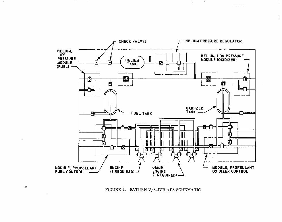
The Saturn V/S-IVB APS consists primarily of a pressurization sub- system , propellant subsystem , engines , and instrumentation. A schematic of the system is shown in Figure I . An isometric view of the component and instrumentation locations within the module is shown in Figure 2. The APS is built in a modular concept in which all subsystems are enclosed inside the structural fairing. Two modules are located on the stage 180 degrees apart on the aft skirt. stage to control the firing of the engines.
Electrical signals a r e generated from the Instrument Unit and
The pressurization system consists of a helium tank, a two-stage regulator, quad check valves, a low pressure helium module (which contains relief and solenoid valves) , and helium f i l l check valves. The initial helium bottle pressure is 3100 psig and is regulated to 196 psia. In the event of a primary regulator failure (wide open or regulating to higher limits is normal failure mode) , the secondary regulator reduces the pressure to 200 psia. quad check valves reduce migration of propellant vapors upstream from the
The ,
propellant tanks to prevent a mixing of explosive propellant vapors.
monomethylhydrazine (MMH) and the other containing nitrogen tetroxide ( N2 04),
1
I i
The propellant subsystem consists of two propellant tanks ( one containing i j
I line filter, f i l l and drain valves, and propellant distribution lines. Each module
2
1
HELIUM PRESSURE REGULATOR A- CHECK VALVES HELIUM, LOW PRESSURE MODU LE (FUEL) 7
I l l I I- I
MODULE, PROPELLANT 0x1 DI Z E R CONTROL
MODULE, PROPEL FUEL CONTROL
FIGURE I. SATURN V/S-IVB APS SCHEMATIC
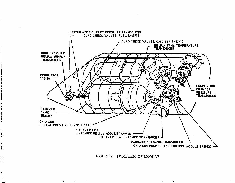
HIGH PRESSURE HELIUM SUPPLY TRANSDUCER
. REGULATOR OUTLET PRESSURE TRANSDUCER QUAD CHECK VALVES, FUEL lA67912 T
\ QUAD CHECK VALVES, OXIDIZER lA67912 HELIUM TANK TEMPERATURE r TRANSDUCER
OXIDIZER LOW PRESSURE HELIUM MODULE 1A49998
OXIDIZER ULLAGE PRESSURE TRANSDUCER
OXIDIZER TEMPERATURE TRANSDUCER OXIDIZER PRESSURE TRANSDUCER
OXID4ZER PROPELLANT CONTROL MODULE lA49422
L
FIGURE 2. ISOMETRIC OF MODULE
contains 127 lbm of MMB and 188 lbm of N2 0, at liftoff. The propellant tanks contain teflon bladders to provide positive expulsion of propellant in zero-g environment. The f i l l and drain valves are contained in the propellant control module, which also incorporates a filter with a nominal filtration rating of 10 microns and an absolute rating of 25 microns.
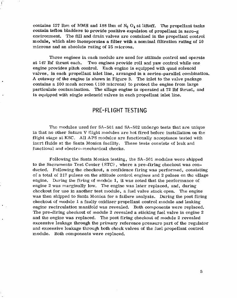
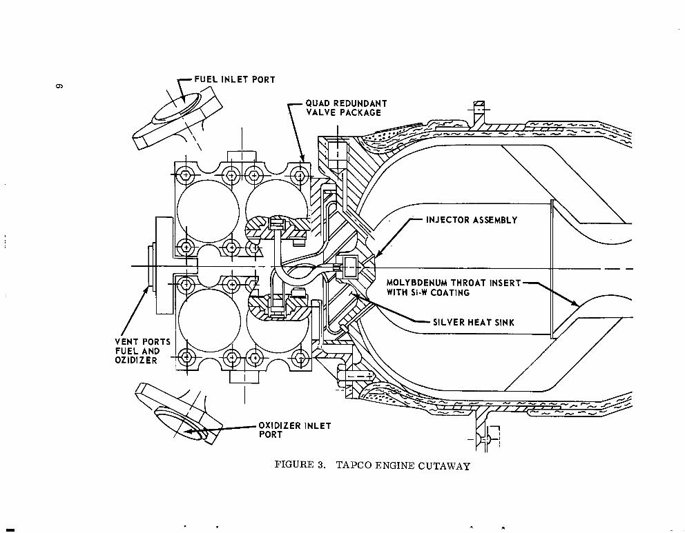
Three engines in each module are used for attitude control and operate at 147 lbf thrust each. engine provides pitch control. Each engine is equipped with quad solenoid valves , in each propellant inlet line , arranged in a series-parallel combination. A cutaway of the engine is shown in Figure 3. The inlet to the valve package contains a 100 mesh screen ( 150 microns) to protect the engine from large particulate contamination. is equipped with single solenoid valves in each propellant inlet line.
Two engines provide roll and yaw control while one
The ullage engine is operated at 72 lbf thrust, and
PRE-FL I GHT TEST1 NG
The modules used for SA-501 and SA-502 undergo tests that a r e unique in that no other Saturn V flight modules a re hot fired before installation on the flight stage at KSC. inert fluids at the Santa Monica facility. functional and electro-m echanical checks.
Al l APS modules a re functionally acceptance tested with These tests consists of leak and
Following the Santa Monica testing, the SA-501 modules were shipped to the Sacramento Test Center (STC) , where a pre-firing checkout w a s con- ducted. Following the checkout, a confidence firing was performed, consisting of a total of 217 pulses on the attitude control engines and 2 pulses on the ullage engine. During the firing of module I, it was noted that the performance of engine 2 was marginally low. checkout for use in another test module, a fuel valve stuck open. w a s then shipped to Santa Monica for a failure analysis. During the post firing checkout of module 1 a faulty oxidizer propellant control module and leaking engine recirculation manifold was revealed. Both components were replaced. The pre-firing checkout of module 2 revealed a sticking fuel valve in engine 2 and the engine was replaced. The post firing checkout of module 2 revealed excessive leakage through the primary reference pressure par t of the regulator and excessive leakage through both check valves of the fuel propellant control module. Both components were replaced.
The engine was later replaced, and, during The engine
5
7 F l ) r E L INLET PORT

Following the confidence firing, both SA-501 modules were flushed with Freon M F to clean the module for handling purposes. The modules were then disassembled and components that had been exposed to propellants were cleaned by vacuum baking or purging. Defective and obsolete-configuration par ts w e r e replaced during the reassembly process. A final post-firing checkout on each APS module was then performed.
Following the disassembly and cleaning, it was discovered that several fuel valves in the engines were stuck. An analysis revealed that the module fuel components were not properly cleaned by the procedure of flushing with Freon M F followed by vacuum baking. A hard residue was found on the engine fuel valves and in other components of the fuel systems. All of the engines were replaced and recleaned by the engine vendor. Five of the six engines used to replace the original 501 module engines had been previously used for the SA-502 APS module confidence firings. The SA-502 modules had experienced the same contamination as SA-501 modules. The engines valves were removed and replaced with new ones and the injectors cleaned before reassembly into the SA-501 modules. The fuel propellant control modules were replaced and all other fuel system components recleaned.
A f t e r completion of the delayed reassembly, the modules were shipped to KSC, where a pre-flight checkout w a s performed. This consisted of leak,
KSC for approximately one year. Af t e r storage the modules underwent pre- liminary checkout and were assembled to the stage. The modules were then given a preloading checkout. During loading operations an oxidizer tank bladder in module 2 was inadvertently overpressurized, and subsequently was replaced.
. functional, and electro-mechanical checks. The modules were then stored at
A "burp" firing was conducted on the APS engines on November 3, 1967, six days before launch. clearing burst, followed by two 65 milliseconds pulses on each attitude control engine with each ullage engine fired for approximately 430 milliseconds. Al l except engine 3 of module 2 exhibited nominal performance. chamber pressure trace indicated a slow and uncharacteristic buildup. Af t e r examining the possible failure modes, it was concluded that the anomaly was caused by instrumentation, and the system w a s judged to be adequate for flight. It was noted during the post flight evaluation that the thrust decay as denoted by Pc was slower on engine 4 module I than engine 4 module 2. A re-examination of burp-firing data revealed that the same result occurred on the pad.
The burp firing consisted of one 200 milliseconds
The engine 3
7
FLIGHT RESULTS
Flight data indicated that attitude control for the S-IVB was maintained within programmed limits throughout the flight in addition to performing all required maneuvers. During the flight the pressurization system operated in a nominal manner and the usage of propellant and pressurant was less than had been predicted. If the mission had been flown without system evaluation instru- mentation, the flight would have been classified as a complete success. instrumentation performed the function for which it was intended and indicated the following anomalies:
The
High Propellant Temperature
Both modules experienced propellant heating, which exceeded expected amounts beginning at approximately I1 000 seconds into the mission. The temperature of the oxidizer in module I exceeded the limits of the temperature transducer ( 5 9 i " R ) . Traces of the temperature are shown in Figure 4.
Slow Chamber Pressure Decay of Ullage Engine
Engine 4 of module 1 exhibited a slower than nominal Pc tailoff for each firing (Fig. 5). from.the full value to IO percent value within 35 dsec from cutoff signal. This value is based upon the close-coupled transducer used for engine manufacture testing and with no surge suppression circuitry.
The specification requires that the thrust level shall decay
Chamber Pressure Osci I lat ions
Engine I of module I exhibited oscillations in chamber pressure of approximately 34 psia peak-to;peak with a frequency of 400 hertz. chamber pressure was 80 psia.
The nominal
Chamber Pressure Decay
J
Engines I and 3 of module 1 decreased in chamber pressure from their initial values to a s low as 55 psia during the mission period from I1 000 seconds to 20 000 secofids of flight.
8

I 0x1 DI ZER TEMPE RATU RE
/ - P O D U L E
0
591.7 R
ULLAGE ENGINES I
5 15 20 25
6o01 FUEL TEMPERATURE I --
I I I I 1
MANEUVER TO LOCAL H O R l Z O N T A L l
ULLAGE ENGINES I
20
\-FIRST BURN OF ULLAGE ENGINES 1 I 5 10 15
540 r TIME FROM LIFTOFF (1000 SEC)
FIGURE 4. PROPELLANT TEMPERATURE
9

150
Y 100 W
z m 50 E n
0
150
Gi n 100
W 9? z m
50 n
0
~ -
APS ULLAGE ENGINE CHAMBER PRESSURE TRACE - MODULE 2
f
NORMAL PRESSURE
__---- ---------
- - ---- -
=q+D ECR EAS E
c
FIGURE 5. ULLAGE ENGINE Pc TRACE
10
Low Chamber Pressures
.
Engines I and 3 of module I were approximately 15 psia low in chamber pressure from the f i r s t firings throughout the mission. module 2 also exhibited lower Pc in flight than that shown during burp firing. Engine I exhibited values from 5 to 10 percent low during the mission. Engine 2 Pc was consistently 8 to 10 percent low throughout the flight. Engine 3 Pc was also lower than expected ( < 5 percent) throughout the flight, but was within system tolerances. and did not cause mission degradation during the flight.
Engines I and 2 of
The anomalies listed were noted in the post flight evaluation
DISCUSSION OF ANOMALIES
High Propellant Temperatures The design of the APS is intended to maintain the propellant temperatures
within acceptable limits by means of passive control. This is done by means of thermal insulators placed in conduction paths to critical components , by insula- tion placed around propellant tanks, by polishing of propellant lines, and by painting the surface of the module with a thermal reflective paint which keeps
the absorbtivity to emissivity ratio - to I. 0. According to McDonnell Douglas
Corporation (MDC) personnel, the effectivity of this coating appeared to be degraded (from the anticipated values) during the earth orbital operation. During development testing, the APS was subjected to extensive thermal environ- mental testing in the MDC high vacuum facility at Huntington Beach. The module was subjected to both hot and cold temperature cycling with a normal surface coating and with a black surface. The tempera- tures in flight could have resulted from one or a combination of the following:
a E
No problems were experienced.
I. ~~~~~ Degraded Surface Paint at Liftoff. The APS modules are normally Since the paint is a silicone
The modules were handled extensively during the The paint was degraded
painted at the Santa Monica manufacturing facility. type, it is easily rubbed off. confidence firings and subsequent checkout operations. to such aneextent that it w a s deemed necessary to repaint the modules at KSC. The effect of the repainting operation is unknown.
2. Degraded Surface Paint Because of Boost Heating. The effect on the surface properties of the paint because of the temperatures experienced during boost is not normally considered to cause any degradation. The Saturn I-B APS modules are treated in the same manner and undergo a similar boost

situation, and no problems have been noted to date. The repainting process must again be noted as representing an unknown effect.
3. Degraded Surface Paint Due to Retro-Rocket _ _ _ Exhaust Plume L m p i n g e m e n t m m a l testing at Huntington Beach included the black paint coating in an effort to produce the worst effect caused by plume impingement. It has been noted, however, that the worst case is really some surface properties
between those represented by the silvery color and black color where the - ratio is greater than I. 0. Thus the effect caused by retro-rocket plume im- pingement represents another unknown.
_- -
a! c
4. Severe Mission Heating Profii. A s stated previously in the intro-
The orientation of the stage to the sun was changed duction, several maneuvers were performed on experiments that are not normal to the Saturn V application. at M 10 800 seconds which produced a higher heat flux on the oxidizer side of module I and fuel side of module 2. The temperature rise began to occur at this point.
Af te r examining each of the possible causes, the most logical explanation fo r the anomaly is a combination of ( 3 ) and (4). Heat transfer calculations by MDC and an examination of the flight data do indicate a degradation of surface properties in earth orbit. Since the Saturn I-B modules have been repainted in the past before flight and the surface coating did not deteriorate, cause ( 1) must be eliminated. Cause (2 ) can also be eliminated because of similarity to Saturn I-B, and the fact that the most severe degradation of the paint, if caused by boost heating, would have occurred on the nose of the module with ve'ry little heating on the aft end. modules towards the sun indicates just the opposite effect. tion of ( 3 ) and ( 4) represents the most probable cause of the anomaly.
The heating caused by orientation of the aft ends of Thus the combina-
Slow Chamber Pressure Decay of Ullage Engine
A s shown in Figure 5, the pressure decay for engine 4 of module I w a s slower than specification limits. The data received represents the first flight environment chamber pressure data ever received for this engine. The decay characteristics are a function of the distance of the pressure detection device from the source of the pressure and the size and volume of line leading to the pressure transducer. The amount of time for decay of the engine from cutoff to 10 percent Pc was less than I second. engine w a s repeatable for both starts in space, and appears to be similar in
The cutoff characteristic for the
12
0
time to the tailoff in the sea level burp firings. The data were discussed with Rocketdyne ( engine vendor) and their opinion was that the engine performed satisfactorily and such traces had been noted in some of their sea level testing. However, the flight trace was different from that nominally expected. Possible causes for the slow tailoff would be:
I. Slow Engine -~ Valve ~ Shutdown. An examination of the trace indicated that the Pc decayed in a normally expected manner down to 25 percent of full value, and then the rate was decreased. Normal operation for a sticky valve would be initial slow movement rather than slow movement at the end of the stroke. The slow movement of a valve poppet would be caused by binding of the poppet within the bore because of thermal expansion, tolerance mismatch, o r contamination. Since the value did move rapidly to near full close condition, this mode of €ailure would appear to be unlikely.
2. Contamination on Valve Seat. Since the valve initially did move rapidly to cutoff propellant flow , but appeared to not seal immediately, a possible explanation could be a particle imbedded in the poppet seal material. Since the same characterist ics a r e noted for both starts and the propellant is flowed through the valve in a steady state operation, any contamination on the seat holding the valve poppet off the seat would have to be imbedded to keep from being washed away. Since the burp firing also indicates a longer than usual tailoff, the possibility of chemical contamination buildup will be eliminated. To have caused slow tail- off in three instances, the particle would have had to be in the seat before sea level firing.
Possibly this could cause such a Pc tailoff.
3. Chamber Pressure Instrumentation Characteristics. The length of line connecting the pressure transducer to the engine chamber is longer than is normally designed for this type of engine. However, since the engine is not a pulsing engine and operates only in a steady state firing mode, the steady state value indicated by the pressure transducer is independent of the length of line. This is not t rue for buildup and shutdown characterist ics, however. The indication of Pc tailoff would be lengthened by the amount of time required for the vacuum environment to empty the line of any gases. It must be noted, how- ever , that engine 4 of module 2 is instrumented in the same manner and the Pc tailoff was significantly faster. blocking the Pc line, this type of tailoff trace would be expected.
Further, if any kind of particle was partially
Several other possible causes, such as valve seat swelling, were ex- amined and eliminated. contamination (which' was imbedded in the teflon) on the valve seat. The uniqueness and minor effect of the anomaly does not indicate that any kind of serious problem exists, or that it should warrant any further study.
The most probable cause was determined to be a slight
13

Chamber Pressure Oscillations
During the period beginning at 16 000 seconds and extending past 20 000 seconds the chamber pressure oscillations of engine I were greater than nominally experienced by the attitude control engines. Oscillations of x 35 psia peak-to-peak were noted at a frequency of 400 hertz. By closely examining all of the attitude control engine Pc traces, it is noted that all engines exhibit some degree of rough combustion. This is a characteristic of the particular engine design. Oscillations at nearly the same frequency have been noted during sea level testing and in previous flights. The magnitude of the previously noted oscillations have been in the 5 to 10 percent psia peak-to-peak range. This type oscillation has not been the cause of any problem in the past even though it is undesirable. Possible causes for the oscillations are as follows:
I. Instrumentation. The pressure transducer normal failure mode is a shift in calibration or loss in reading. Pressure transducer failure indicating oscillations of the type indicated in flight have not been observed in any previous testing. puts from the rate gyros verified this, indicates that the transducer was per- forming normally. perform until the end of flight.
The fact that the engine chamber pressure was low initially, and out-
The data indicates that the transducer w a s continuing to
2. High Propellant Temperature. The oscillation occurred during the periods of highest propellant temperatures. temperature were investigated in testing by the engine vendor and in system testing at MSFC. in previous ground testing. Because of propellant manifold fluid dynamics , the oxidizer can theoretically vaporize in the lines when the temperatures are high and propellant inlet pressures drop during engine start operations. I t is prob- able that these conditions existed during the chamber pressure oscillations. The high propellant temperature in conjunction with low propellant inlet pressure has been simulated in MSFC testing, and chamber pressure oscillations very similar to the flight oscillations were obtained.
The effects of high propellant
No oscillations of the type experienced in flight w e r e noted
3. Reduced _____ Propellant FW. The engine that experienced oscillations w a s also running with reduced chamber pressure. A possible cause of low chamber pressure could be reduced propellant flow caused by a restriction in the propellant flow path. This would indicate a lower than nominal propellant inlet pressure upstream of the engine injector or increased injector resistance. The propellant pressure drop necessary to cause a 15 percent drop in engine Pc is simulated in tests at MSFC. section.
55 psia. The combination of ( 2 ) and reduced propellant flow was The result of the tests will be discussed in a later
14

Chamber Pressure Decay
The decay in chamber pressure of engines I and 3 of module I occurred during the period of high propellant temperatures ( Fig. 6 ) . temperature was the obvious suspect after reviewing the data and noting the correlation between the chamber pressure decay and oxidizer temperature rise. The result of high engine injector and oxidizer temperature and normal manifold pressure oscillations would be a reduction of flow caused by vapori- zation of the propellant in the feed system. cause of the anomaly, and the test section wi l l cover the results of the MSFC tests to verify the cause of the anomaly.
The high propellant
This was determined to be the
Low Chamber Pressures
Degraded performance was noted in engines I and 3 of module I and engines I and 2 of module 2. low in Pc near the beginning of APS operation and continued at those levels or lower throughout the mission. were 5 percent low in Pc would not normally be considered an anomaly since instrumentation, engine tolerance, etc. , would allow for this. However, for this mission, the low Pc values may indicate a trend. A comparison of test and flight engine chamber pressure is shown in Figure 7.
Four engines were approximately 10 to 15 percent
The remaining two attitude control engines that
Burp firings of the engines six days before flight verified that each engine w a s performing in a nominal manner. verification of nominal integrity. remained in the module for flight. pressurized to nominal operating pressure in a routine manner. indications at liftoff were that the SA-501 APS w a s ready for flight.
This firing 'represents the last The same propellants used in the burp firing Immediately before liftoff the A P S was
Thus all
Considering the low Pc at beginning of flight the following possible causes w e r e examined:
Instrumentation e r r o r
Change in throat area
Engine valve malfunctions
Particulate contamination
Chemical contamination
These possible causes are discussed below:
15

TIME FROM LIFTOFF (1000 SEC)
MODULE 1 OXIDIZER tii 0 MODULE 1 FUEL
560
55 0
540 0 2 4 6 8 1 0 1 2 1 4 16 18
TIME FROM LIFTOFF (1000 SEC)
5
26
FIGURE 6. ENGINE CHAMBER PRESSURE/TEMPERATURE TRACE

h
4 - 1oc
Y
W K 3 v) v) W K
K W
n
m 3 E 9c
8(1
202 50i
50 1
I I I I 160 180 200 220 240
MANIFOLD PRESSURE (PSlAd
FIGURE 7. COMPARISON OF TEST AND FLIGHT ENGINE CHAMBER PRESSURE
Instrumentation Error . The first logical candidate was instrumentation. Since this is The magnitude of the decreased chamber pressure was M 15 psia.
essentially sea level ambient pressure, a shift in reference pressure of the transducers would be suspected. The last recorded bench calibration of the transducers recorded in the module log book was about the middle of 1966, approximately one and a half years before flight. However, even though the internal reference pressure is sea level ambient, the loss of the reference pressure would increase rather than decrease the chamber pressure reading. A study of rate gyro and position indicator data by MDC also indicated that the suspect engines were operating in a degraded manner. Thus, it is coneluded that instrumentation was not the cause of the anomaly.
Change in Throat Area. An enlargement in throat area caused by throat erosion or loss of throat insert would result in a reduction in chamber pressure. However, this type of engine failure has not occurred since early in the engine development program. Furthermore, there was no firing o r condition that would cause this to occur during the period between burp firing and the first firings in flight. under the flight conditions is so remote that this mode of failure is not worthy of further discussion.
The possibility that a ser ies of throat failures would occur in one flight
Engine Valve Malfunction. ~- The attitude control engines use quad re- These valves a r e dundant valves in each propellant line to control the flow.
designed to eliminate a single point failure in either a fail-to-open o r fail-to- close mode. Valve failure mode testing w a s performed on these engines by the vendor during the development and qualification program. simulating both failure-to-open and failure-to-close to determine the effect upon the engine performance. series-parallel valve arrangement caused a Pc decrease of 5 psia. mode would not provide the characteristics noted in flight. exhibited nearly the same degradation early in flight, the engine valves would appear to be an unlikely source.
Tests were run
The case of a fail-closed valve in one leg of the
Since four engines This failure
The probability of valve failures of the same nature occurring at near the same time to produce the same result in four engines is highly unlikely. This reasoning would place any type of engine propellant valve malfunction in the same category as an improbable failure candidate.
Particulate Contamination. - Precautions a r e taken to ensure that no particulate contamination is allowed to enter the system both during buildup and testing and by means of fluids loaded into the module. cleanliness procedures imposed for all operations, and use of filters both within
These precautions are

the modules and in the GSE. In spite of the precautions , however , particulate contamination has been found in the system. Metal particles have in a number of instances either caused leakage past a valve seat or caused binding of a valve poppet in the bore. These problems occurred primarily during develop- ment testing. In none of the cases was a degradation in engine performance of the magnitude experienced in SA-501 flight noted.
Examining the system (Fig. 1) , it is noted that only propellant feed
The line size from lines, a fi l ter , propellant valves, and engine injector constitute the flow path from the tank outlet to the engine combustion chamber. the tank outlet to the filter entrance is 3/4 inches in diameter. feeds all engines, n6 flow restriction occurred in this section. levels for the filters are 10 microns nominal and 25 microns absolute. retically, the maximum size particle that could pass through the filter would be 9. 84 x The clogging of the filter by particulate contamination must also be ruled out since the flow for all four engines in each module passes through the filter, and effects of clogging would be seen on all engines alike. The size of the primary propellant feed line from the filter to the engines is 3/8 inches in diameter. The arrangement is such that the propellant flows through the filter into a cavity at the filter base in the propellant control module where it is fed from two manifolds to the engines. Thus, if flow w a s restricted in the propellant control module cavity, it would be seen by all engines but if it was restricted in the manifolds feeding engines 1 and 3, then engines 2 and 4 would be unaffected or vice versa. Stated simply, the problem occurred downstream of the pro- pellant control module, either in the manifolds feeding the engines, o r in the engines themselves .
Since this line The filtration
Theo-
inches in diameter. The length of such a particle is indeterminate.
Again reviewing the system, it is noted that even if the main propellant feed lines to the engines are blocked upstream of the engine flange the engines can still receive propellants through the smaller ( 1/4 inch ID) recirculation lines. Testing at MSFC indicates that even with the primary propellant inlet lines completely blocked, the engines still operate with a Pc of approximately 85 psia. If the manifold to two engines was restricted, the result should be' the same on both engines. propellant flow restriction to be in the engines themselves unless the recircula- tion line is also restricted.
This was not the case. This fact would indicate any
A cutaway view of the engine is shown in Figure 3. The engine flow path contains a 100 mesh (filtration level of 150 microns) screen filter at the valve entrance (recirculation line is downstream of filter) , the solenoid operated quad valves, a flow control orifice at the valves outlet, 12 capillary feed tubes on the
19

oxidizer side, one feed tube for fuel, and the engine injector. valves open to a distance of 0. 040 f 0. 003 inches off their seats. If contamina- tion blocked the opening and reduced the stroke of the poppet, leakage would occur. However , if the contamination had built up behind the poppet , the propellant flow area would be reduced in the valve open position, and no leakage would occur in the closed position. The reduction in movement of the poppet would reduce the Pc buildup rates due to restriction of flow. In order to cause Pc reductions of the order experienced in flight, at least one valve in each parallel leg of one propellant would have to be affected in each engine. Partic- ulate contamination would not appear to be a logical condidate to cause at least eight valves (two in each engine) to be restricted. It is noted that the back side of the valve poppet is essentially a ffdead-endedff volume. Particulate contami- nation would be more likely to occur somewhere along the flow path, and build up at a flow restriction (fi l ter , orifice, etc. ) ra ther than in the poppet bore.
The propellant
The flow control orifices have a minimum diameter of 0. 060 inches. The size of particle required to clog the orifice would have to be of such a size that it would not be able to pass through the fi l ters and valves unless it was fluid in nature (i. e. a chemical gel) . of the flow restriction.
This would not be the most logical source
The oxidizer is fed into the engine injector by 12 capillary feed tubes that a r e nominally 0. 0355 inches in diameter and 3. 183 inches in length. fuel feed tube is nominally 0. 1190 inches in diameter and approximately 2. 5 inches in length. inches in diameter while the twelve fuel injector holes are 0. 0283 inches in diameter. Again a single particle of particulate contamination required to clog any of the openings would not logically be able to pass through the filters up- stream. Unless a particle is generated within the valve package itself, a particle large enough to cause the flow restriction necessary for the Pc decay should not be the source of the problem. The probability that an accumulation of smaller particles is deposited in a flow path in four engines is unlikely unless all cleanliness precautions were completely ignored. The burp firings showed this not to be the case before lift off.
The
The twelve injector oxidizer holes are nominally 0. 0354
Because of filters, sizes of lines and openings in the flow paths, and other factors, it is concluded that particulate contamination (external or internally induced solid particles) is probably not the cause of the performance degradation.
Chemical Contamination. ___ Chemical contamination for this discussion is defined as contamination that is generated by reactions within the system
20

between propellants, system hardware, and the ambient atmosphere. The following types of chemical contamination w e r e examined:
N2O4 flow decay
Propellant/moisture/hardware incompatibility.
N204 Flow Decay. The N2O4 flow decay phenomenon is one in which either a gel-like mass of propellant res t r ic ts the opening to a flow passage, or a mass of material is deposited on the wa l l of flow restrictions (orifices, valves, etc. ) . ferrous nitrate [ ( No) Fe NO,)^ ] that is formed when the propellant has been stored or has been in contact with ferrous materials. It must be noted that not a single case of flow decay occurring in a propulsion system during a simulated mission propulsion test has been documented. have always been in tes t facilities where an attempt was being made to induce the phenomena or a long duration steady flow of propellant w a s being passed through a facility to test some specific component. most knowledgeable on the subject, flow decay occurs when a decrease in temperature occurs in the propellant at a place in the system where a pressure drop occurs. required to initiate flow decay has not been thoroughly defined. Tests indicate that small changes in temperature ( < 5' F) can cause the decay to begin occur- ring at a flow restriction. decay to disappear.
The material deposited has been determined to be crystallizable
The instances observed
According to personnel
The magnitude of the temperature and pressure drops that is
Increasing propellant temperature causes the flow
The conditions experienced by the APS on the launch pad before flight and during the boost phase of flight are not considered to be conducive to flow decay since there was no propellant flow during this period. of the contaminant out of the propellant while in the quiescent state on the launch pad would tend to settle into the bottom of the propellant tank, and during flow would be expected to collect on the propellant control module filter. Any restriction of flow through the filter would be reflected on all engines alike. This did not occur. The amount of contaminant that could form in the propellant feed system while on the pad would be so small that it should not clog any com- ponent in the system. Based on the conditions that existed in the APS, it was determined that N2O4 flow decay was not the cause of the anomaly.
Any precipitation
Propellant/Moisture/Hardware Incompatibility. Reactions can occur between the oxidizer (N204) and water to produce nitric acid, which attacks' many metals to some degree. Since no previous problems had been noted in ground testing or flights, it was assumed that no problem existed in the basic
21

compatibiltiy of the propellant with the system materials. Procedures for handling and processing of system hardware contain steps to eliminate and control the amount of water that may be in the system. The resul t of excessive corrosion products in the system would be either the restriqtion of flow passage o r anomalous operation of components. discussed and determined to be unlikely causes of the low chamber pressure.
Failures of components have been
The other phase of the chemical corrosion is the restriction of the flow passages. Since study has indicated that the cause of the problem is in the engines, the only likely area that would experience the conditions of exposure of propellant flow passage hardware to a combination of propellant ( N204) and water is downstream of the engine valves. entrance to the capillary feed tubes and the injector flow passages. and tubes are constructed from Inconel 600 material , which contains a high percentage of nickel (70 percent) and significant percentages of iron and chromium. Nickel and its alloys are generally accepted as being compatible with anhydrous N204 but are susceptible to attack by nitric acid.
This would include the cavity at the The injector
Very little concern had been expressed about the incompatibility of the nitric acid and the hardware since there has been considerable testing during the engine development, system development and qualification, and inhouse MSFC testing with no apparent problem. In addition four flights of the Saturn I-B A P S had not revealed any anomalies of low chamber pressure similar to the SA-50I flight problems. However, after examining the other possible causes, this area appeared as a likely candidate for the problem cause.
Contacts with JPL and MSC concerning their experience with this type phenomenon indicated that the S-IVB APS should be susceptible to the nitric acid corrosion problem. maneuvers experienced corrosion of the injector because of the formation of nitric acid after the injector was exposed to N204 and water . It w a s reported that the effect of the injector corrosion was reduction in chamber pressure. The effect was noted in sea level tests and was postulated to have been a pos- sible cause of a flight engine failure. propellant occurred during the engine assembly hot acceptance test and sub- sequently, because of inadequate cleaning and contact with moisture the cor- rosion occurred. The MSC personnel reported that a limit had been placed on the time that an engine injector that is burp fired on the pad can be exposed to the atmospheric conditions without being cleaned.
The engines used in the Surveyor program for Delta V
The exposure of the Surveyor injector to
22

Another input which indicated that this phenomenon w a s the problem was the results of a series of tests conducted by MDC at their Sacramento test facility on a Saturn V APS module. The objective of the program w a s to determine the adequacy of the system to withstand extended hold periods, simulating launch aborts. Burp firings were conducted on the engines at the start of the 9O-day program and at i5-day intervals thereafter.
Two engines began to exhibit low chamber pressure after the first 15- day period and continued to decrease at succeeding firings. A meeting between personnel from MDC and MSFC resulted in the conclusion that the problem could be a reduction of the oxidizer flow caused by a buildup of the nitric acid/ hardware corrosion products in the engine injector. It was decided that MSFC should conduct a series of tests on a single engine to simulate the launch pad conditions to verify the validity of the assumed probable cause. Results of the tests (which are presented in the next section of this document) indicated that the assumption was correct.
MSFC TEST RESULTS
A special test program w a s conducted at the MSFC Test Laboratory Storable Propellant Facility to provide an experimental base for defining the APS Pc anomalies observed during the SA-50i flight. directed toward reproducing the SA-501 flight effect and identifying the con- tributing cause( s) . five specific phases involving single engine as well as complete module testing at both sea level and simulated altitude conditions. effort are discussed below.
This test effort was
To accomplish this , the test program w a s divided into
The results of this test
APS Module Testing
An initial test series w a s conducted on the Saturn V Phase IV Test APS
In these tests the APS engine firing density Module in an attempt to reproduce the Pc decay phenomenon observed in the latter portion of the AS-501 flight. was approximated and significant module temperature conditions experienced during the SA-501 flight w e r e simulated. Tests were conducted in the MSFC Test Laboratory i2-foot diameter altitude cell at a simulated pressure altitude of 120 000 feet.
23
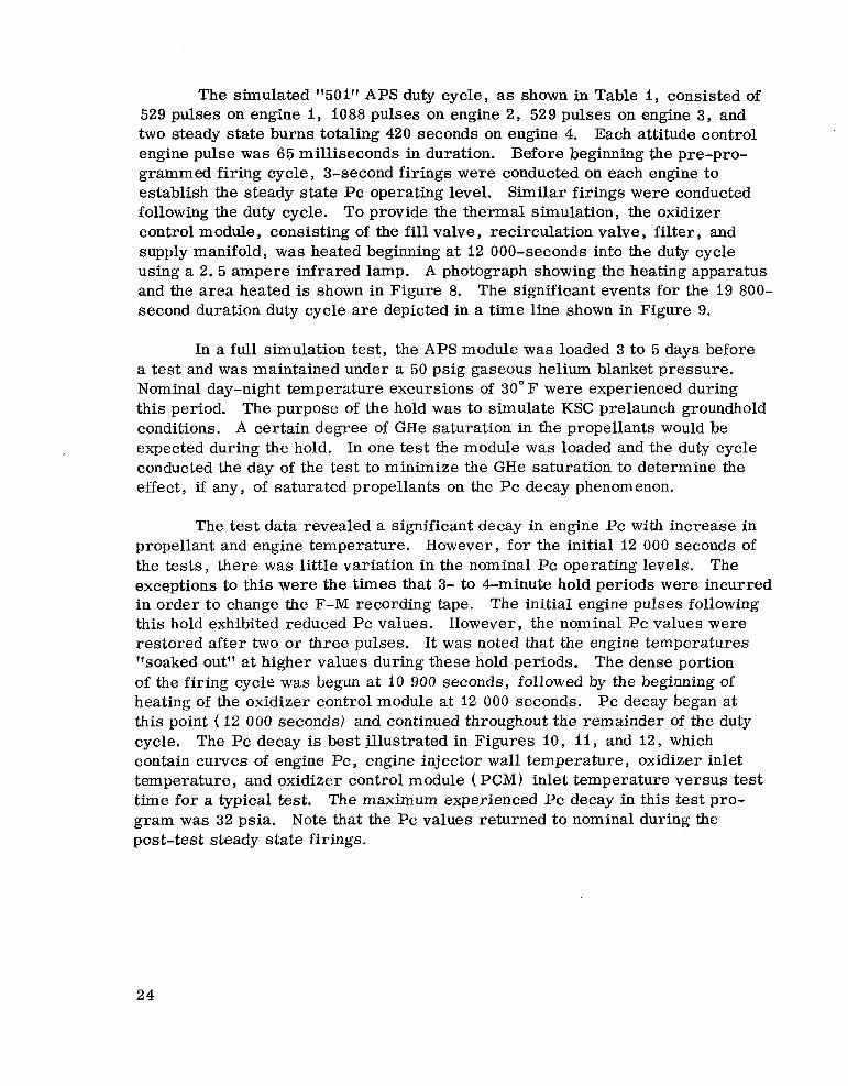
The simulated "501" APS duty cycle, as shown in Table I, consisted of
Each attitude control 529 pulses on engine I, 1088 pulses on engine 2 , 529 pulses on engine 3 , and two steady state burns totaling 420 seconds on engine 4. engine pulse was 65 milliseconds in duration. Before beginning the pre-pro- grammed firing cycle, 3-second firings were conducted on each engine to establish the steady state Pc operating level. Similar firings were conducted following the duty cycle. To provide the thermal simulation, the oxidizer control module , consisting of the f i l l valve , recirculation valve , filter , and supply manifold, was heated beginning at 12 000-seconds into the duty cycle using a 2 . 5 ampere infrared lamp. A photograph showing the heating apparatus and the a rea heated is shown in Figure 8. The significant events for the 19 800- second duration duty cycle are depicted in a time line shown in Figure 9.
In a full simulation test, the APS module was loaded 3 to 5 days before a test and w a s maintained under a 50 psig gaseous helium blanket pressure. Nominal day-night temperature excursions of 30" F were experienced during this period. The purpose of the hold w a s to simulate KSC prelaunch groundhold conditions. A certain degree of GHe saturation in the propellants would be expected during the hold. In one test the module was loaded and the duty cycle conducted the day of the test to minimize the GHe saturation to determine the effect, if any, of saturated propellants on the Pc decay phenomenon.
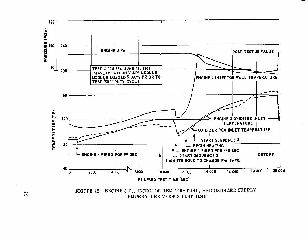
The test data revealed a significant decay in engine Pc with increase in propellant and engine temperature. However, for the initial 12 000 seconds of the tests, there was little variation in the nominal Pc operating levels. exceptions to this were the times that 3- to Pminute hold periods were incurred in order to change the F-M recording tape. this hold exhibited reduced Pc values. However, the nominal Pc values were restored after two or three pulses. It was noted that the engine temperatures "soaked outf' at higher values during these hold periods. The dense portion of the firing cycle was begun at 10 900 seconds, followed by the beginning of heating of the oxidizer control module at 12 000 seconds. P c decay began at this point ( 12 000 seconds) and continued throughout the remainder of the duty cycle. contain curves of engine Pc , engine injector wall temperature , oxidizer inlet temperature, and oxidizer control module ( PCM) inlet temperature versus test time for a typical test. The maximum experienced Pc decay in this test pro- gram was 32 psia. Note that the Pc values returned to nominal during the post-test steady state firings.
The
The initial engine pulses following
The Pc decay is best illustrated in Figures 10, 11, and 12, which
24

tv 01
---.-.~---
~
~ .oXIDIZ~R PCM INLET LINE
, ~
d"!.!! OXIDIZER FILTER
'; k~
FIGURE 8. AREA OF APS MODULE HEATED IN SIMULATED "501" TESTS
---

NOTE: SEE TABLE I FOR THE ENGINE FIRING RATES FOR SEQUENCES 1,2, AND 3.
START PULSE SEQUENCE 3
START HEATING OXIDIZER PCM
ULLAGE ENGINE FIRE FOR 330 SEC
PULSE SEQUENCE 1 START PULSE SEQUENCE 2
ULLAGE ENGINE FIRE FOR 90 SEC
0 660 SEC 10 900 12 000 START 11 160 12660
FIGURE 9. SEQUENCE OF EVENTS TIME LINE FOR SIMULATED "501" DUTY CYCLE
TABLE I. SIMULATED 17501" APS ENGINE FIRING PROGRAM
Time ~~
0-10 900 sec*
660-750 see
10 900-12 660 sec"
I 1 160-11 490 sec
12 660-19 800 sec"
Engine I
2 pulses/ 100 sec
- -
14 pulses/ 100 sec
I pulse/ I 1 0 sec
._
Engine 2
8 pulses/ 100 sec
~. ..
8 pulses/ 100 sec
1 pulse/ 95 sec
~~ .
~-
Engine 3
I pulse/ 250 sec
25 pulses/ 100 sec
I pulse/ 66 sec
I 19 800
CUTOFF
~
Engine 4
'$ Pulse Width = 65 milliseconds
26

g 100 v) v) W pc n
h
LL 0
w pc 3 c 4 n! W n
v
3 c
160
TEMPERATURE 120
80
40
ELAPSED TEST TIME (SEC)
FIGURE I O . ENGINE 1 Pc, INJECTOR TEMPERATURE, AND OXIDIZER SUPPLY TEMPERATURE VERSUS TEST TIME
100

120 h
i v) n Y
W
5 100 v) v) W eL n
80 J' L
ENGINE 2 Pc
I
PNGINE 2 OXIDIZER INLET TEMPERATURE
. _ - -- I
ELAPSED T€ST TIME (SEC)
FIGURE 11. ENGINE 2 Pc, INJECTOR TEMPERATURE, AND OXIDIZER SUPPLY TEMPERATURE VERSUS TEST TIME
120 A
1 E Y
w
i loo Y, w G! n
80
h3 W
240
- 200
160
A
LL
120 0, w PL 2 a W n 5 80
TEST C-008.534; JUNE 11, 1968 I I PHASE IV SATURN V APS MODULE , I MODULE LOADED 5 DAYS PRIOR TO ENGlNk 3 INJECTOR WALL TEMPERATURE
/
0
OXIDIZER INLET TEMPERATURE I
TEMPERATURE I
I
f t- START SEQUENCE 3 BEGIN HEATING I f- ENkNE 4 FIRED FOR 330 SEC
1
START SEQUENCE 2 I CUTOFF L- 4 MINUTE HOLD TO CHANGE F- TAPE
h I 1 2000 4000 8000 10 000 12 000 14 000 16 000 18000 20( 40
0
ELAPSED TEST TIME (SEC)
FIGURE 12. ENGINE 3 Pc, INJECTOR TEMPERATURE, AND OXIDIZER SUPPLY TEMPERATURE VERSUS TEST TIME
DO
The results from the MSFC tests substantiated the theory that the cause of the decay in engine Pc was vaporization of the oxidizer in the injector and injector feed tubes due to elevated propellant and/or engine temperature. hydraulic resistance created by the presence of gas in this area restricted oxidizer flow, therefore resulting in the Pc drop. The cause of the N2O4 vaporization, as stated above, was a combination of hot hardware and hot pro- pellant. With the hot injector and injector tubes, a condition aggravated by high propellant temperature, the temperature of the N2O4 was elevated to the point that it gasified before reaching the injection orifices. Pc values were restored during the post-test steady state runs as the propellant inlet temperature dropped and , subsequently engine hardware temperature was lowered because of the continuous flow of cooler propellant through the injector and injector feed tubes , further substantiated oxidizer gasification as the cause of Pc decay.
The
The fact that nominal
Gaseous helium saturation in the propellant showed no effect on the Pc decay phenomenon. engine performance in the form of low frequency combustion instability of * 8 to 10 psia amplitude, 300 hertz frequency. Additional discussion on the effect of saturation is contained in the following sub-section.
The primary influence of GHe saturation was in oscillatory
Single Engine Altitude Testing To more specifically investigate propellant temperature effect on engine
Pc, six tests were conducted on one TRW attitude control engine in the MSFC 3-fOOt diameter altitude cell as a follow-up to the previously discussed APS module tests. The objectives of this test ser ies were to isolate the effects of saturated propellant , engine temperature , propellant temperature , and the combination of these variables on engine performance.
The engine firing cycle as outlined in Table I1 w a s utilized in each run, and a 3-second firing was conducted immediately after each duty cycle to obtain post-test steady state performance. The initial three tests used unsaturated oxidizer at temperatures of 80" F, 140" F, and 160" F. The last three tests used GHe saturated oxidizer at these same temperatures.
The effect of GHe saturation on engine Pc decay was not significant. However, the data indicated that the saturation contributed to unstable per- formance with nominal Pc oscillations of * 5 to * 8 percent of rated Pc. Also during the initial pulses, the Pc value decreased to as low as 70 psia as gas passed through the engine.
30
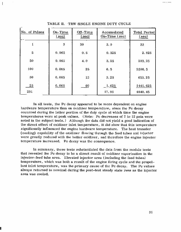
TABLE II. TRW SINGLE
i
5
231
ENGINE DUTY CYCLE
3
0 . 0 6 5
0 . 0 6 5
0 . 0 6 5
0 . 0 6 5
0 . 0 6 5
Off-Time - ( sec)
30
0. 5
4. 0
2 5
13
60 -
Accumulated On-Time (sec)
3 . 0
0 . 3 2 5
3 . 2 5
6. 5
3 . 2 5
1 .625
17 .95
Total Perioc ( sec)
33
2. 825
203.,25
2506 .5
653 .25
1441.625
4840.45
In all tests, .the Pc decay appeared to be more dependent on engine hardware temperature than on oxidizer temperature, since the Pc decay occurred during the latter portion of the duty cycle at which time the engine temperatures w e r e at peak values. (Note: Pc decreases of 7 to 12 psia were noted in the subject tests. 1 Although the data did not yield a good indication of the direct effect of oxidizer inlet temperature, it did show that this temperature significantly influenced the engine hardware temperature. (cooling) capability of the oxidizer flowing through the feed tubes and injector w e r e greatly reduced with the hotter oxidizer, and therefore the engine injector temperature increased. Pc decay was the consequence.
The heat transfer
In summary, these tests substantiated the data from the module tests that revealed the Pc decay to be a direct result of oxidizer vaporization in the injector-feed tube area. temperature, which was both a result of the engine firing cycle and the propel- lant inlet temperature, was the primary cause of the Pc decay. The Pc values always returned to nominal during the post-test steady state runs as the injector a rea was cooled.
Elevated injector a rea (including the feed tubes)
31
I

TRW Single Engine Sea Level Testing
Another series of tests was conducted to investigate the step function Pc drop noted in the 501 APS engines. six days earlier, and the engines, containing the residual propellants, were exposed to the atmosphere during the hold period. conducted by MDC, Sacramento, California, resulted in similar cases of Pc decay. Consequently, the test program was initiated at MSFC to determine the relation of the Pc decay phenomenon to the interaction between propellants remaining in the engine at shutdown, air moisture, and engine materials. In support of this objective, hot firings were conducted on single TRW engines and the Saturn V APS module, and NzO4 flow tests were conducted on two TRW engine injectors.
Pre-flight burp firings were conducted
"Sea level-hold" tests
The single engine testing is discussed in this section.
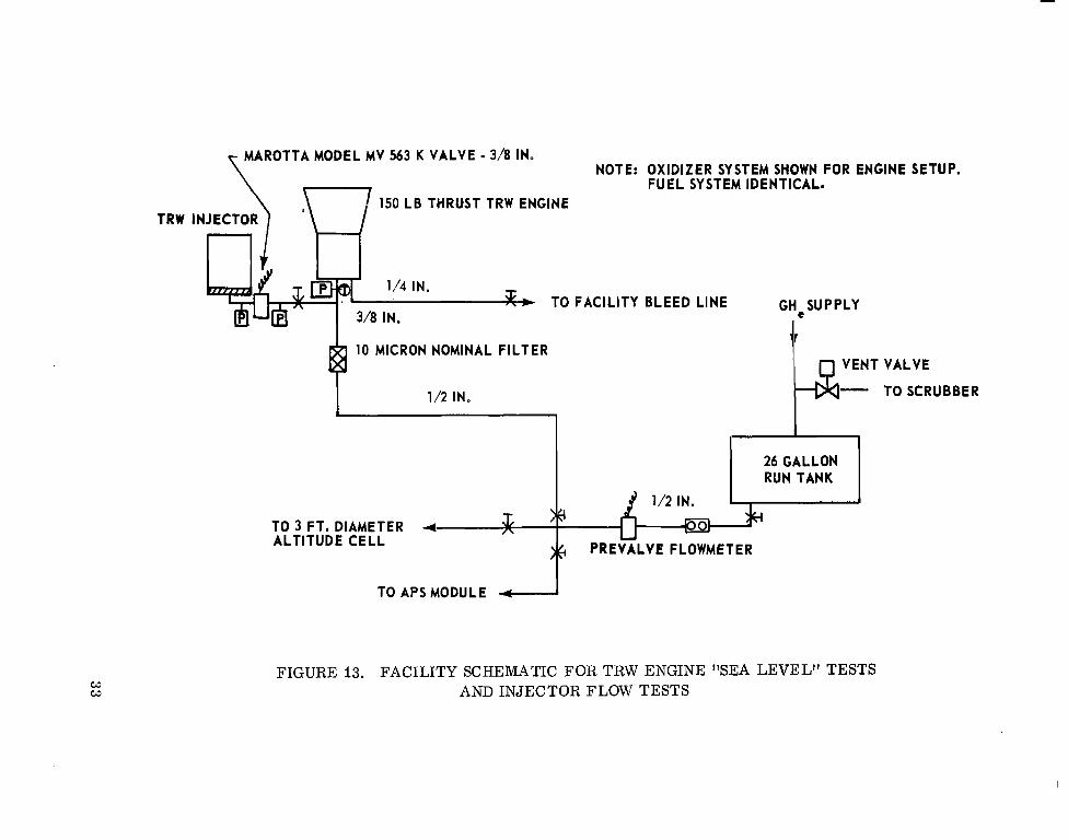
Two TRW engines were hot fired in a series of 16 tests at ambient pressure conditions. tubing schematic as shown in Figure 13. engine inlets under 20 psig blanket pressure during hold periods. duty cycle for these tests consisted of three pulses: 250 milliseconds on - 500 milliseconds off, 65 milliseconds on - 500 milliseconds off, and 65 milli- seconds on.
The engines were mounted in a "sea level" stand with the
The standard Propellants were maintained at the
The initial engine tested (TRW SN 585) exhibited a Pc of 99 psia and O/F ratio of 1. 630. After a 5-day hold period, the engine w a s tested again, using the identical inlet pressures as the first run. with an O/F ratio of 1. 003. The fuel flowrate remained nominal. Following the second test, the engine was disassembled and inspected by the Materials Division of P&VE Laboratory. Crystalline matter was noted at the entrance to the twelve 0. 035-inch diameter oxidizer injector feed tubes. Although the tube a rea reduction caused by the material did not appear to be large, the effect of these particles on the tube surface roughness in the form of increased friction factor and reduced flow area was such that flow restriction could be experienced.
The Pc value was 70 psia
A ser ies of tests was then begun on a second TRW engine ( S N 526). An 11 percent reduction in Pc..was noted during the initial 6-day period, and the Pc decreased to a low of 81 psia from the initial value of 99 psia ( 18 percent). Seven tests over a 21-day period were required to reach this level. A s with the previous engine, the Pc decay was proportional to the decrease in oxidizer flow rate. In this case the O/F shift was from I. 631 to 1. 300. Fuel flow rate remained constant. From the low of 81 psia the Pc began to increase again and stabilize at 94 psia after 4 tes ts in a 14 day period. A 10-second steady state run was then conducted and the Pc returned to the nominal value of 99 psia after I. 5 seconds burn time.
32
w w
MAROTTA MODEL MV 563 K VALVE - 3/8 IN. NOTE: OXIDIZER SYSTEM SHOWN FOR ENGINE SETUP.
FUEL SYSTEM IDENTICAL. 150 LB THRUST TRW ENGINE
TRW INJECTOR
3, TO FACILITY BLEED LINE GHeSUPPLY II
10 MICRON NOMINAL FILTER + I 1/2 IN.
VENT VALVE
TO SCRUBBER -
I I 26 GALLON RUN TANK
1/2 IN.
TO 3 FT. DIAMETER ALTITUDE CELL
PREVALVE FLOWMETER
TO APS MODULE
FIGURE 13. FACILITY SCHEMATIC FOR TRW ENGINE "SEA LEVEL" TESTS AND INJECTOR FLOW TESTS
TRW Injector Flow Testing
The particulate matter discovered in the oxidizer injector feed tubes in engine 585 prompted a series of injector flow tests. The injector was removed from a TRW engine previously fired at MSFC in APS module performance test- ing, and special connectors were fabricated to mate the injector oxidizer inlet fitting to the facility oxidizer supply line. The engine valves were replaced by a single facility solenoid valve to eliminate the engine valves variable. Nitrogen tetroxide ( N204) was then flowed through the oxidizer injector feed tubes , through the injector, to the atmosphere. A protective dust cover was placed over the injector following each test.
A 5-test series was conducted over a 16-day period on one injector ( SN 106) , and this injector was then removed from the stand and delivered to P&VE Laboratory for contaminant analysis. Microscopic examination revealed the presence of contamination at the entrance to the oxidizer tubes in the form of a greenish, jelly-like substance. percentage of nickel and lesser percentage of iron and chromium in the contami- nation. Although the injector was open to the atmosphere for a day or more during the laboratory examination, liquid was noted in the injector. The liquid was postulated to be nitric acid and litmus paper tests proved it to be acidic. Photographs were made and views of the contaminated portions of the injector are shown in Figures 14 to 17. Figure 14 shows the contamination in the oxidizer tubes entrance flange. Figure 15 shows the same view of a flange that had been cleaned. The other two photographs illustrate the difference in amount of corrosive attack on the front face of an injector at the outlet of the oxidizer tubes for two injectors, one which was used in this test ( Fig. 16) , and one used in early system tests (Fig. 17) .
Spectrographic analysis indicated a high
APS Module "Hold" Testing
The Saturn V Phase IV Test APS Module was used for a series of tests to obtain "system'' test data on the "sea level firing-hold" induced Pc decay phenomenon. Initially engine number I was fired through a duty cycle consisting of 3 pulses of 250, 65, and 65 milliseconds duration at ambient pressure condi- tions. A Pc value of 99 psia was observed. A 9-day hold period was incurred and the module was fired at a simulated altitude pressure of 100 000 feet. Engine number 1 Pc decayed to 84 psia. The other two attitude control engine Pc's were within the nominal value tolerance, although from 2 to 3 psia low. The altitude cell remained evacuated for several minutes following the altitude run, thus resulting in the evaporation of residual propellants remaining
34

FIGURE 14. CONTAMINATED ENGINE INJECTOR OXIDIZER FLANGE INLET
35

FIGURE 15. CLEANED ENGINE INJECTOR OXIDIZER FLANGE INLET
36

FIGURE 16. CORROSIVE ATTACK ON INJECTOR OXIDIZER PASSAGE OUTLET
37
l
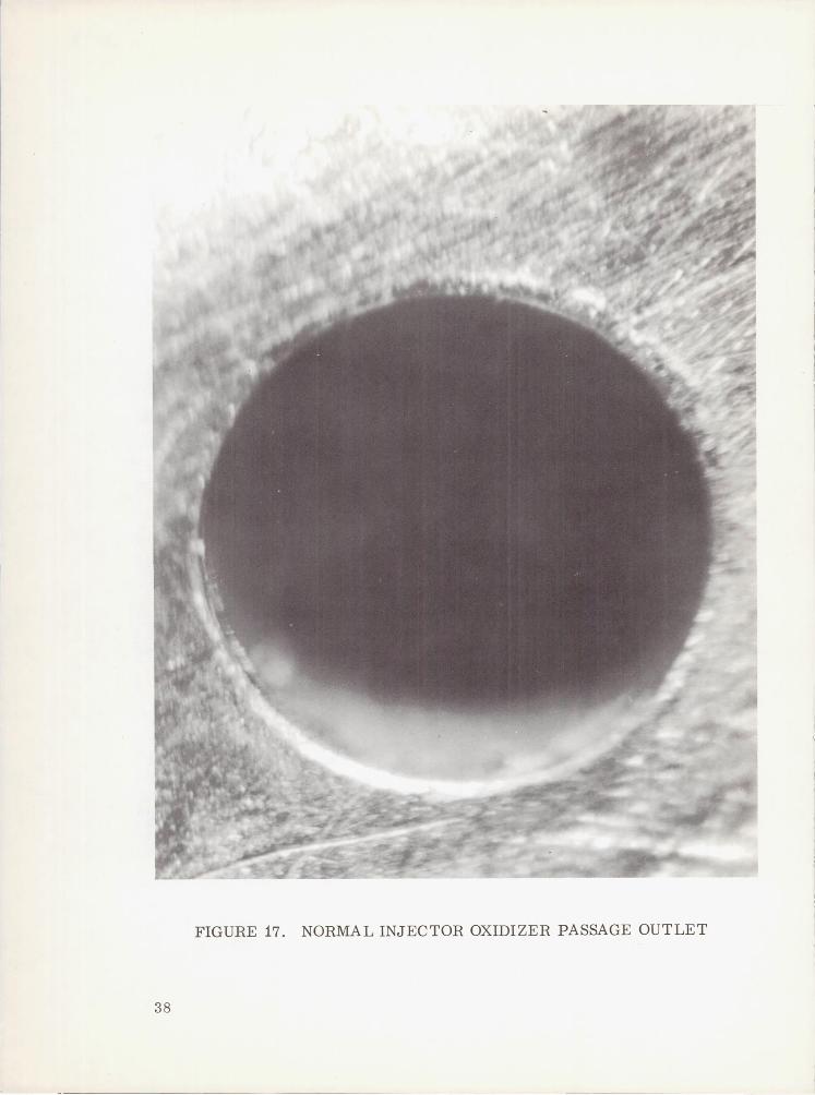
FIGURE 17. NORMAL INJECTOR OXIDIZER PASSAGE OUTLET
38
in the engines at shutdown. engine I Pc returning to a nominal value of 100 psia. conducted on all engines resulted in the Pc values returning to 100 to I 0 1 psia and stabilizing. oxidizer injector feed tubes w e r e "washed out" during the steady state firings.
Additional firing cycles at altitude resulted in Steady state firings
Apparently small amounts of contaminants contained in the
Test S u m ma ry The APS module and TRW single engine tests discussed under APS
Module Testing and Single Engine Altitude Testing revealed that Pc decay occurred as a result of oxidizer vaporization in the engine injector and injector feed tubes. Elevated temperature in the injector ,area, which includes the twelve oxidizer feed tubes, w a s the cause of vaporization. was dependent on both the engine firing cycle and the propellant inlet tempera- ture. the injector a rea w a s cooled.
This temperature
The Pc values always returned to nominal during steady-state runs as
The primary results derived from the single engine and APS module hot firing tests and the injector flow tests discussed under TRW Single Engine Sea Level Testing, TRW Injector Flow Tests, and APS Module "Hold" Testing are summarized below.
When an engine was fired at ambient pressure, and then allowed to stand with residual propellants, a marked Pc decay occurred in subsequent firings. The Pc decay was a direct consequence'of decreased oxidizer flow; the fuel flow remained nominal. the entrance of the oxidizer injector feed tubes. Analysis of injectors following N204 flow tests revealed this material to be primarily constituted of nickel, with lower percentages of iron and chromium. The oxidizer feed tubes a r e constructed of Inconel 600, which contains greater than 70 percent nickel with significant percentages of chromium and iron. Therefore, oxidizer combined with the moist air to form nitric acid, which in turn apparently reacted with the Inconel to form nickel nitrate and/or ferrous nitrate compounds, which caused the flow restriction.
The oxidizer flow decay w a s caused by material buildup at
During steady state firings of several seconds duration, the Pc values returned to nominal as the restricting material appeared to wash out.
The APS engine firing data, although limited, indicated no occurrence The obvious of Pc decay in tests conducted following a prior test at altitude.
conclusion here is that the residual propellant w a s vaporized at the vacuum conditions, and thusly the oxidizer-metal reaction was precluded.
39
I

Engine firings, even after several days hold period, that followed prior steady state firings of several seconds ( I O or more) at ambient pressure condi- tions, indicated no Pc decay. Apparently the engine became hot enough during the extended run to vaporize any residual propellants.
CONCLUS IONS
The APS anomalies experienced during the SA-501 flight were:
1. High propellant temperature
2. Slow chamber pressure decay of ullage engine
3 . Chamber pressure oscillations
4. Chamber pressure decay
5 . Low chamber pressure.
After investigating the anomalies and performing a series of tests to verify the assumed causes of the problems, it was concluded that the high propellant temperature and low chamber pressure anomalies warranted remedial action to preclude possible future mission problems.
The testing at MSFC verified that the 501 flight APS gradual chamber pressure decay and oscillations, noted in the latter portion of the mission, were a direct result of the high propellant temperature. Although the high propellant temperature was in part a result of the unique 501 mission profile (not typical for Apollo) , flight data analysis showed that the passive thermal control for the APS was less than expected. Thus, a need for additional thermal isolation of the propellant feed system is needed. The solution, implemented by MDC, is the addition of: ( 1) new radiation shields in the propellant manifold area inside of the module, ( 2 ) fiberglass covers over the servicing disconnects located externally on the aft end of the module to shield them from direct solar heating, and (3 ) new brackets that attach the propellant lines to the primary structure which will serve as thermal insulators to prevent conduction of heat from the structure into the propellant lines. The design changes were based upon the results of analytical studies performed by MDC and should correct the problem.
40
. . .
It ---
The low APS chamber pressures observed throughout the 501 flight represent degradation of engine performance, although possibly one the system could endure without serious mission consequences. This performance degradation has been reproduced in post flight ground test and found to be a result of clogging in the oxidizer flow passages. It appears to be a function of the number of t imes that the engine is burp fired, the period of exposure to sea level conditions, and other factors such as temperature of the hardware, relative humidity of the a i r , orientation of the engine, and vacuum exposure. The degree to which each independent factor affects the engine performance is unknown and would require a significant amount of testing in a stringently controlled environment to determine. A s stated in previous sections, the problem has been experienced in other systems and the effect of a combination of Nz04 and water on Inconel has been studied in the past. However, because no similar anomalies had been experienced in the S-IB Flights o r ground tes ts , the problem was not considered to be serious. The reason for this inherent problem not being identified earlier is probably twofold. for forming the obstructing residue were negated during most system tests and single engine tests by either the fact that engines were purged with GN, following test and/or the test firing cycle was such that sufficient heat was generated within the engine to vaporize all residual propellants. Secondly, there is evidence that the obstructing residue is relatively soft and easily washed out at sea level conditions; however, under vacuum conditions this residue may become crystalline and extremely difficult to dislodge. The second reason is considered the possible key as to why the low chamber pressure problem was peculiar to the Saturn V and not experienced during Saturn IB flights. V compared to 2 minutes for Saturn IB. by the APS prior to initial firing in flight is different for Saturn IB. results to determine the effect of these vslriables on the clogging phenomenon a re not yet available, but testing effort is underway.
Firstly, conditions
The time line from lift-off to initial APS firing is 8 minutes for Saturn In addition, the level of vacuum seen
Test
The conclusion is that the low chamber pressure was caused by chemical contamination; specifically, reactions between nitric acid and engine injector hardware caused the oxidizer flow passages to be clogged. The nitric acid was formed by allowing the oxidizer to come in contact with moisture in the ambient air on the launch pad. probable cause of the flight anomaly.
The testing at MSFC has verified this to be the
The solution to the problem is to not expose the engine injector to N204 and wateq and to not hold at sea level condition for sustained periods of t ime (days) . The method to accomplish this is the deletion of the burp firing re- quirement before launch. This is being implemented and should eliminate
41
further problems of this nature. checkout, loading, and launch procedures so that the deletion of the burp firing does not cause any significant decrease in confidence that the system is ready for flight.
Enough confidence has been gained in the
The other anomaly was the slow chamber pressure decay of the ullage engine. The probable cause was attributed to a small particle of contamination imbedded in the engine valve seat. This is considered to be a random occur- rence, and only careful adherence to cleanliness requirements would be any aid in eliminating the problem. No effect on the mission w a s noted due to the occurrence, and it is not considered to be worthy of any further study except to watch for any future occurrences.
In conclusion, it is considered that with the modification of hardware
Further and launch procedures being implemented, that the SA-50i APS flight anomalies have been identified and their causes eliminated for future flights. testing to provide a more definitive explanation to some of the assumptions is still in progress and should be useful in future designs.
George C. Marshall Space Flight Center National Aeronautics and Space Administration
Marshall Space Flight Center, Alabama, January 1969 904-24-03-0000-50-529
42
~ __ .. __ . .. . ...
NASA-Langley, 1969 - 28 M355
.. .. I. I I
NATIONAL AERONAUTICS AND SPACE ADMINISTRATION WASHINGTON, D. C. 20546
OFFICIAL BUSINESS FIRST CLASS MAIL
POSTAGE A N D FEES PAID NATIONAL AERONAUTICS AND
SPACE ADMINISTRATION
POSTMASTER: If Undeliverable (Section 158 Postal Manual) Do Nor Return
“The aeroaaiitical and space activities of the United States shall be condzfcted so as t o contribute . . . to the expansion of hziman knowl- edge of phenomena in the atmosphere aiad space. T h e Adniinistrrttion shall provide for the widest practicable and appropriate dissenzinatioiz of inf oriiiation concerniizg its actitdies and the resalts thereof.”
-NATIONAL AERONAUTICS AND SPACE ACT OF 1958
NASA SCIENTIFIC AND TECHNICAL PUBLICATIONS
TECHNICAL REPORTS: Scientific and technical information considered important, complete, and a lasting contribution to existing knowledge.
TECHNICAL NOTES: Information less broad in scope but nevertheless of importance as a contribution to existing knowledge.
TECHNICAL MEMORANDUMS : Information receiving limited distribution because of preliminary data, security classifica- tion, or other reasons.
CONTRACTOR REPORTS: Scientific and technical information generated under a NASA contract or grant and considered an important contribution to existing knowledge.
TECHNICAL TRANSLATIONS: Information published in a foreign language considered to merit NASA distribution in English.
SPECIAL PUBLICATIONS: Information derived from or of value to NASA activities. Publications include conference proceedings, monographs, data compilations, handbooks, sourcebooks, and special bibliographies.
TECHNOLOGY UTILIZATION PUBLICATIONS: Information on technology used by NASA that may be of particular interest in commercial and other non-aerospace applications. Publications include Tech Briefs, Tcchnology Utilization Reports and Notes, and Technology Surveys.
Details on the availability of these publications may be obtained from:
SCIENTIFIC AND TECHNICAL INFORMATION DIVISION
NATlO NA L AERO N AUTlCS AND SPACE ADM I N ISTRATION Washington, D.C. 20546