Investigation of Loss of Power and Water Production at ... · PDF fileThis report documents...
22
Investigation of Loss of Power and Water Production at Sohar Power Company, May 2015
Transcript of Investigation of Loss of Power and Water Production at ... · PDF fileThis report documents...

Investigation of Loss of Power and Water Production at Sohar Power Company, May 2015

Page 2 of 22
SYNOPSIS
This report documents the Investigation of Loss of Power and Water Production at Sohar Power
Company, May 2015 undertaken for Authority for Electricity Regulation, Oman.
Page 3 of 22
CONTENTS
EXECUTIVE SUMMARY ................................................................................................................... 4
LIST OF ABBREVIATIONS ............................................................................................................... 6
1.0 INTRODUCTION ................................................................................................................ 7
1.1 Brief Description of Sohar Power and Desalination Plant .................................................. 7
1.1.1 Power Generation ................................................................................................. 7
1.1.2 Desalination ........................................................................................................... 7
1.1.3 Sea Water Intake System ..................................................................................... 9
1.1.4 Sea Water Supply Pumps ..................................................................................... 9
1.1.5 Sea Water Supply Control System. ..................................................................... 10
1.1.6 Signal Exchange between MISC and Sohar-1 Power and Desalination Plant ... 10
2.0 SEQUENCE OF EVENTS................................................................................................ 11
3.0 ANALYSIS OF THE SEQUENCE OF EVENTS .............................................................. 15
3.1 Root Cause Analysis ........................................................................................................ 15
3.2 Summary .......................................................................................................................... 16
3.3 Restoration of Plant .......................................................................................................... 16
3.4 Observations .................................................................................................................... 18
4.0 RECOMMENDATIONS .................................................................................................... 20
Appendices
APPENDIX 1 - SITE PHOTOGRAPHS

Page 4 of 22
EXECUTIVE SUMMARY
On 3
rd May 2015 at 20.50 hours, there was a rupture of the sea water supply pipe to the Oman Oil
Refineries and Petroleum Industries Company (ORPIC) facilities. This caused flooding of the sea water intake area and the local switchgear and control room for the Sohar Power Company (SPC) seawater supply pumps. Although the ORPIC pumps stopped about 10 minutes after the pipe broke, a significant volume of sea water entered the area resulting in plant tripping for other customers in the area. It was reported water continued to back-flow from the broken pipe for some 30 hours. During this time, although the SPC seawater intake was flooded, the SPC plant remained in service. The extent of the flooding made dewatering works difficult to complete safely, but all affected parties cooperated to clear and clean the area. The SPC plant continued to operate normally until 5
th May 2015 at 12:14 hours, when seawater pump
#5 tripped which resulted in the SPC steam turbine tripping. At this point water production was not interrupted. This trip is considered most likely to be due to a fault on a cable between the instruments in the field and the local control room due to a lengthy submersion in seawater. Later that day at 18.52 hours, whilst investigations were being carried out to determine why seawater pump #5 tripped, the remaining seawater pumps tripped which resulted in a total loss of power and water production. The outage of the plant resulted in extensive water shortages in North Batinah region and caused inconvenience to the public. The reason for the compete plant shut down was attributed to a very high level of spurious alarm signals being raised that caused the communication link between the field instruments and the control system to fail. It is believed the alarms were generated due to seawater getting into the cables due to damage of the protective outer layers of cables. After being submersed in seawater for a lengthy time short circuits developed resulting in spurious alarm signals being generated. The loss of full electricity and water production was recognised as being a serious problem and efforts continued to dewater the area, cable pits, cable cellars, checking and cleaning of field instrumentation. This continued through the night and on 6
th May 2015 the plant operator, STOMO activated its Crisis
Management plan, mobilising additional staff to site to support the clear-up and testing. Attempts were made to restart the power plant on the 7
th and 8
th May 2015, each time resulting in all
seawater supply pumps being tripped. In an attempt to isolate the cause of the trips, all field cables from field instruments associated with seawater supply pumps 5 and 6 were disconnected, which then enabled the plant to be successfully restarted. An examination of the plant Operation Manual indicates that the plant could have been restarted without reliance on pump 6. Had procedures in the plant Operation Manual been followed, it is considered likely that water production could have been restored a lot earlier than was realised in practice. On 19
th May 2015 at 19:39 the entire power plant tripped again due to the loss of all seawater supply
pumps. Again the cause was identified as a failure of the communication link between the field instruments and the control system. A Siemens specialist working remote from Germany discovered the signals from MISC were forced to simulate that the seawater differential level across the intake screens is in a healthy state The pump controller requires the sea water differential level signals from MISC to be in the healthy state in order to run the seawater pumps. When communication to the control system fails, the MISC signals default to the unhealthy or trip state. This then causes all of the seawater pumps to trip and/or prevent them from being starting, resulting in the whole plant being tripped

Page 5 of 22
The root cause of the power plant tripping on the 5th and 19
th May 2015 is related to the damage to
instrument cables in the seawater intake area due to the flooding caused by the rupture of the ORPIC seawater pipe. The delays in restoring production relates to failure of communication link between the field instruments and control system and the forced logic being used in the control system. This forced logic is likely to have been in place since the plant was commissioned, but did not affect the plant until there was a failure of the communication link between the field instruments and the control system caused by the flooding of the seawater into the intake area on 3
rd May 2015.
Although recognising the efforts of all involved in attempts to restore production in a challenging working environment, the investigators believe that had the plant Operation Manual been understood and followed, water production could have been resumed much earlier than it was. The overall impact on water production capability of the SPC plant between 3
rd and 22
nd May is illustrated below.
Flooding
Water
Production
Date
Water production capability
21
-May
22
-May
15
-May
16
-May
17
-May
18
-May
19
-May
20
-May
09
-May
10
-May
11
-May
12
-May
13
-May
14
-May
03
-May
04
-May
05
-May
06
-May
07
-May
08
-May
Page 6 of 22
LIST OF ABBREVIATIONS
AER Authority For Electricity Regulation, Oman
BOO Build-Own-Operate
BRP Brine Recirculation Pump
DCS Distributed Control System
DHI Doosan Heavy Industries
GTG Gas Turbine Generator
HAZID Hazard Identification
HAZOP Hazard and Operability
HH High High
HRSG Heat Recovery Steam Generator
IM Interface Module
IPP Independent Power Project
IWPP Independent Water and Power Project
MISC Majis Industrial Supply Company
MIS Main Interconnected System
MSF Multi Stage Flash
O&M Operation and Maintenance
OPWP Oman Power and Water Procurement Company
ORPIC Oman Oil Refineries and Petroleum Industries Company
PWPA Power and Water Purchase Agreement
RCA Root Cause Analysis
RO Reverse Osmosis
SPC Sohar Power Company
STG Steam Turbine Generator
SWP Sea Water Pump
STOMO Suez - Tractebel Operation and Maintenance Oman LLC
WPOE WorleyParsons Oman Engineering LLC

Page 7 of 22
1.0 INTRODUCTION
The Sohar-1 Power and Desalination Plant owned by Sohar Power Company SAOC (SPC) supplies
power to the Main Interconnected System (MIS) and water to the public networks in North Batinah
region of Sultanate of Oman. The water supply for the region is heavily and solely dependent on this
desalination plant and operation of the desalination plant is very critical.
On May 3rd
2015 at 20.50 hours, there was flooding of the sea water intake area and the local
switchgear and control room for the power plant seawater supply pumps due to a rupture of the sea
water supply pipe to the Oman Oil Refineries and Petroleum Industries Company (ORPIC) facilities.
Although the plant remained operational while dewatering works were in progress, the complete power
plant tripped on 5th May 2015 at 18.52 hours resulting in loss of production of power and water. The
outage of the plant resulted in extensive water shortages in North Batinah region and caused
inconvenience to the public.
In this regard, Authority of Electricity Regulation, Oman (AER) has engaged the services of
WorleyParsons Oman Engineering LLC for an independent assessment of the plant outage to
understand the causes of the outage and provide recommendations to mitigate against a future
reoccurrence.
1.1 Brief Description of Sohar Power and Desalination Plant
The Sohar-1 Power and Desalination Plant was established under a Build-Own-Operate (BOO)
scheme for which enables SPC to operate the plant for a period of 15 years under a Power and Water
Purchase Agreement (PWPA) with the Oman Power and Water Procurement Company (OPWP) who
is the single buyer of power and water for all IPP/IWPP projects within the Sultanate of Oman.
The plant comprises of 585 MW combined cycle gas fired power plant and 150,000 m3/day
desalination plant located in the Sohar Industrial Port area in the North Al Batinah region of the
Sultanate of Oman. A simplified schematic process diagram for the plant is presented in Figure 1.
1.1.1 Power Generation
The power plant uses three Siemens SGT5-2000E Gas Turbine Generators (GTG) (formerly known as
V94.2), each fitted with Heat Recovery Steam Generators (HRSG), which utilize the exhaust heat of
the gas turbines to produce steam. The steam generated from HRSG is supplied to one condensing
steam turbine to complete the combined cycle. The Steam Turbine Generator (STG) manufacturer is
Alstom. The balance of the steam produced from the HRSG’s is supplied to the desalination plant. The
HRSGs are dual pressure natural circulation with a horizontal gas flow manufactured by Doosan
Heavy Industries.
1.1.2 Desalination
The desalination plant comprises four conventional Multi Stage Flash (MSF) units. Each MSF unit is
designed to produce 37,500m3 of desalinated water per day at design conditions. Each MSF unit has
17 heat recovery stages and 3 heat rejection stages. The seawater intake and outfall are part of the
Sohar Industrial Port area common facilities and are owned by the Government of Oman and operated
by Majis Industrial Supply Company (MISC). The potable water is exported through a connection at
the site boundary to OPWP potable water network.
MSF is a water desalination process that distillates sea water by flashing a portion of the water into
steam in multiple stages of what are essentially counter-current heat exchangers. The sequence has a
cold end and a hot end while intermediate stages have intermediate temperatures. The stages have
different pressures corresponding to the boiling points of water at the stage temperatures.

Page 8 of 22
Figure 1: Simplified Process Schematic for Sohar Power and Desalination Plant

Page 9 of 22
1.1.3 Sea Water Intake System
Sea water flows from the sea into the sea water screening chamber. The sea water is chlorinated to
control the growth of marine organisms. The chlorinated sea water passes through screens to remove
debris. The screened sea water then passes through to a distribution chamber and into covered pump
chambers. The intake, screening chamber, chlorination facilities, distribution chamber and pumping
chambers are owned and operated by MISC. MISC has instruments to monitor the differential water
level across the screens (upstream in forebay and downstream in distribution bay), as indicated in
Figure 2 ,in order to prevent damage to the screens.
1.1.4 Sea Water Supply Pumps
The sea water supply pumping system comprises two separate sea water pumping and supply
systems for the four MSF desalination units and the power plant. Four sea water pumps (3 working +
1 standby) are provided to supply sea water to the four MSF desalination units. For the power plant,
one sea water pump is provided to supply cooling water to steam turbine condenser and one auxiliary
sea water pump is provided to supply cooling water to closed cycle auxiliary cooling water system for
gas turbine and steam turbine auxiliaries. Each sea water supply pump is provided on its discharge
side with a combined shut off and non return valve.
The distribution header for the sea water supply system is divided into two headers with an isolation
control valve (with bypass), normally operated in closed condition. If the sea water pump supplying
cooling water to steam turbine condenser or if the sea water pump supply cooling water to the GTG
and STG auxiliaries, trips, the control valve is opened to supply sea water to maintain cooling to the
power plant.
A simplified schematic process diagram for the plant is presented in Figure 2.
Figure 2: Simplified Schematic of the Sea Water Supply System

Page 10 of 22
1.1.5 Sea Water Supply Control System.
The Sohar-1 Power and Desalination Plant uses the Siemens Teleperm XP Distributed Control
System (DCS) to control and monitor the complete plant.
Field wiring associated with the sea water supply pumps are wired to I/O modules (FUM modules)
installed in local racks. The I/O signals are then communicated to the DCS Automation Processors via
communication interface modules (IM 614). The control logic used to control and monitor the seawater
pumps resides in the DCS Automation Processor. The DCS Automation Processors, power supplies,
and communication modules are arranged into a redundant configuration. The I/O signals from the I/O
modules are not redundant.
1.1.6 Signal Exchange between MISC and Sohar -1 Power and Desalination Plant
In normal operating conditions, the difference in the level of seawater upstream of the screens and the
level of seawater downstream of the screens (∆S) is expected to be approximately 0.200 m. A screen
may become unsafe if the difference in seawater level across the screens becomes excessive.
To avoid structural failure, hardwired signals were originally provided to trip the sea water supply
pumps as follows:
if ∆S reaches 2.000 m and is increasing, alarm signal 1 will be activated;
if the sea water pumps fail to shut down in response to alarm signal 1 and ∆S reaches 2.500 m and is increasing, alarm signal 2 will be activated
if the sea water pumps fail to shut down in response to alarm signal 2 and ∆S reaches 3.000 m and is increasing, the sea water supply pumps would be tripped.
From the investigation it was found these signals were not commissioned, instead the signals were
forced to the healthy state in the I/O module and were communicated as healthy signals to the DCS
Automation Processor via the communication interface module.

Page 11 of 22
2.0 SEQUENCE OF EVENTS
On 3rd May 2015 at 20.50 hours, flooding took place at the sea water intake facility due to a rupture of
the sea water delivery pipe to the ORPIC facilities. A summary of the sequence of events leading to
tripping of the Sohar-1 Power and Desalination Plant and restoration of the plant are presented in
Table 1.
Date Time Event Fault Comments
03-05-2015 20.50 ORPIC sea water delivery pipe rupture
-
05-05-2015
12.14 Sea Water Pump 5 and steam turbine tripped
I/O signals exchanged between the communication interface module and the Distributed Control System (DCS) Automation Processors failed leading to Pump 5 tripping. This resulted in the loss of cooling water to the steam turbine condenser, leading to loss of vacuum and tripping of the steam turbine.
The tripping of SWP-5 was caused by short circuits on instrumentation field cables to field instruments associated with SWP-5, most likely due to ingress of sea water by the fact the cables were submerged in sea water for approximately 3 days. It is believed the ingress of sea water was due to the protective outer sheath of these cables suffering damage when originally installed or by deterioration since being installed; otherwise sea water could not have entered the cable and cause cable short circuits.
The I/O faults from SWP-5 field cables did not cause a complete communication failure between the IM communication interface modules and the DCS Automation Processors ;otherwise, all of the seawater pumps would have tripped.
18.52
All sea water pumps tripped and complete power and desalination plant tripped.
Communication failure between the I/O communication interface modules and the DCS Automation Processors resulted in the DCS Automation Processors not receiving the required healthy sea water level differential signals. Therefore loss of the healthy state (in Automation Processors) of forced sea water level signals caused all the six(6) sea water pumps to trip
The damaged instrumentation field cables associated with SWP-5, SWP-6, MISC signals and other signals from sea water intake cause a large swarm of I/O faults that eventually caused a complete communication failure between the IM communication interface modules and the DCS Automation Processors.
All the seawater pumps tripped due to the HH differential level signal from MISC, which is forced to the healthy state in the FUM I/O card, resets to its default state which is trip when communication between Interface Module/s and the Automation Processor/s is lost.
06-05-2015 Dewatering, cleaning and testing carried out. STOMO Crisis Management activated
07-05-2015
Dewatering, cleaning and testing continues. Siemens specialist support mobilised
22.10 Plant started with Sea Water Pump 6.
08-05-2015 1.34 GTG 3 declared
Page 12 of 22
Date Time Event Fault Comments
available
2.55 GTG 1 declared available
4.37 GTG 2 declared available
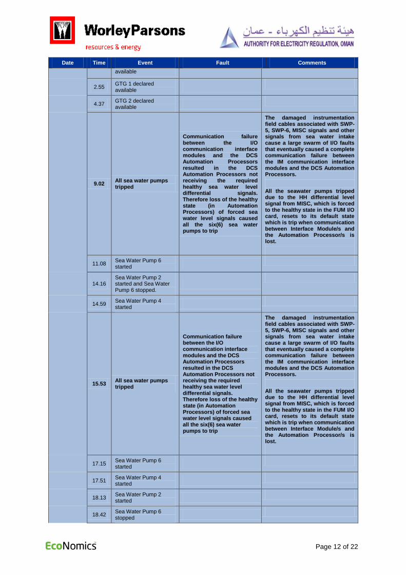
9.02 All sea water pumps tripped
Communication failure between the I/O communication interface modules and the DCS Automation Processors resulted in the DCS Automation Processors not receiving the required healthy sea water level differential signals. Therefore loss of the healthy state (in Automation Processors) of forced sea water level signals caused all the six(6) sea water pumps to trip
The damaged instrumentation field cables associated with SWP-5, SWP-6, MISC signals and other signals from sea water intake cause a large swarm of I/O faults that eventually caused a complete communication failure between the IM communication interface modules and the DCS Automation Processors.
All the seawater pumps tripped due to the HH differential level signal from MISC, which is forced to the healthy state in the FUM I/O card, resets to its default state which is trip when communication between Interface Module/s and the Automation Processor/s is lost.
11.08 Sea Water Pump 6 started
14.16 Sea Water Pump 2 started and Sea Water Pump 6 stopped.
14.59 Sea Water Pump 4 started
15.53 All sea water pumps tripped
Communication failure between the I/O communication interface modules and the DCS Automation Processors resulted in the DCS Automation Processors not receiving the required healthy sea water level differential signals. Therefore loss of the healthy state (in Automation Processors) of forced sea water level signals caused all the six(6) sea water pumps to trip
The damaged instrumentation field cables associated with SWP-5, SWP-6, MISC signals and other signals from sea water intake cause a large swarm of I/O faults that eventually caused a complete communication failure between the IM communication interface modules and the DCS Automation Processors.
All the seawater pumps tripped due to the HH differential level signal from MISC, which is forced to the healthy state in the FUM I/O card, resets to its default state which is trip when communication between Interface Module/s and the Automation Processor/s is lost.
17.15 Sea Water Pump 6 started
17.51 Sea Water Pump 4 started
18.13 Sea Water Pump 2 started
18.42 Sea Water Pump 6 stopped

Page 13 of 22
Date Time Event Fault Comments
21.55
Sea Water Pump 5, Sea Water Pump 6 and air compressor signal cables disconnection started.
09-05-2015
5.42 MSF 4 normalized and production started.
7.29 GTG1 declared available
9.33 GTG 2 declared available
12.10 MSF 3 normalized and production started.
16.29 Sea Water Pump 3 started
18.18 GTG 3 declared available
22.23 STG declared available
11-05-2015 9.15 MSF 1 normalized and production started.
18-05-2015 1.28 MSF 2 normalized and production started.
19-05-2015 19.39
All sea water pumps tripped and complete power and desalination plant tripped.
Communication failure between the I/O communication interface modules and the DCS Automation Processors resulted in the DCS Automation Processors not receiving the required healthy sea water level differential signals. Therefore loss of the healthy state (in Automation Processors) of forced sea water level signals caused all the six(6) sea water pumps to trip
The damaged instrumentation field cables associated with MISC signals and other signals from sea water intake cause a large swarm of I/O faults that eventually caused a complete communication failure between the IM communication interface modules and the DCS Automation Processors.
All the seawater pumps tripped due to the HH differential level signal from MISC, which is forced to the healthy state in the FUM I/O card, resets to its default state which is trip when communication between Interface Module/s and the Automation Processor/s is lost.
20-05-2015
2.48 Sea Water Pump 6 started
3.27 Sea Water Pump 2 started
4.30 GTG 1 declared available
6.40 GTG 3 declared available
6.43 Sea Water Pump 1 started
16.42 MSF4 normalized and production started.
17.58 MSF 3 normalized and production started
20.00 GTG 2 declared

Page 14 of 22
Date Time Event Fault Comments
available
21-05-2015 1.40 MSF2 normalized and production started.
22-05-2015
1.40 Sea Water Pump 3 started.
3.55 MSF 1 normalized and production started.
Table 1: Main Sequence of Events

Page 15 of 22
3.0 ANALYSIS OF THE SEQUENCE OF EVENTS
3.1 Root Cause Analysis
The Root Cause Analysis (RCA) was done for the sequence of events which led to the fault and
tripping of the Plant. The summary of the RCA is as described in Table 2 below:
Sl No. Analysis Observations
1 What is the problem? Sea water pumps tripped resulting in the complete shutdown of the Sohar-1 Power and Desalination Plant.
2 When did it happen? 18.52 hours on 5th May 2015.
3 Where did it happen? Trip signal to shut down the pumps was given by the Distributed Control System.
4 Why did it happen?
1. The sea water delivery pipe to ORPIC facilities ruptured on 3rd May 2015 at
20.50 hours. The sea water from the ruptured pipe drained into the sea water intake area of the Sohar-1 Power and Desalination Plant and other adjacent intake areas. This resulted in flooding of the sea water pumps instrumentation and cable pits, MISC signal cables, air compressor container and basement of local switchgear and control room with water level reaching 1-1.5 m above ground.
2. Communication between the DCS Automation Processors and the I/O rack for Pumps 5 & 6 was continuously being interrupted and being re-established.
3. Loss of communication was because the communication interface modules were going into a faulted state due to swarm of fault alarms coming from the field instrumentation cables. (The communication interface modules themselves were not faulty).
4. Field cables to pumps 5, 6, MISC and other signals in sea water intake area were initiating numerous sporadic fault signals that appeared to be the reason for the communication interface modules going into a faulted state.
5. The numerous sporadic fault signals were likely being generated due to signal short circuits in the field cables caused by loss of cable insulation integrity.
6. The sea water stood for about 3 days and in all probability this led to the loss/compromise of cable insulation integrity. (Likely due to the sea water ingress via the outer cable sheath due to damage sustained when the cables were installed or subsequently afterwards by rodents, see Appendix 1).
7. The pump control logic in the DCS requires the sea water HH differential level signal from MISC to be in the healthy state. These signals were not connected to DCS since Commercial Operation Date.
8. Sea water HH differential level signals were forced in DCS I/O FUM module to healthy state and communicated to DCS Automation Processors to allow Sea water pumps to start.
9. When there is a complete failure of communication between the IM modules and the DCS Automation Processors, the rack I/O’s are set to their default state which is 0. Therefore on loss of communication the HH differential level signal from MISC, which is forced to the healthy state in the FUM I/O card, resets to its default state which is trip.
10. Loss of the forced healthy signal causes all six sea water pumps to trip and/or prevent them from running.
5 What is the significance of the problem?
Loss of the sea water supply has a direct impact shutting down the Sohar-1 Power and Desalination Plant. As the Sohar-1 Power and Desalination Plant is the only major source of desalinated water in the North Batinah region any disruption has serious consequences for the wellbeing of people rely on this as the only source of potable water.
Table 2: Summary of Root Cause Analysis

Page 16 of 22
3.2 Summary
The root cause of the power plant tripping on the 5th
and 19th May 2015 is related to the damage to
instrument cables in the seawater intake area due to the flooding caused by the rupture of the ORPIC seawater pipe.
The delays in restoring production relates to forced logic being used in the control system. Forced
logic was configured in the I/O card that otherwise would have received the seawater differential levels
signals from MISC. The forced logic was used to force the control system to believe the seawater
differential level across the intake screens was OK. This condition had to be healthy for any of the
seawater pumps to run. It was not discovered until the 19th May 2015 by Siemens Engineer in
Germany that force logic was configured in the I/O module. Up to this time any condition that could
cause a loss of communication between the I/O card with the forced logic and the DCS Automation
Processor would likely cause the entire plant to trip.
After the first plant trip on the 5th May 2015, O&M staff believed the cause was faulty communication
cables and/or communication modules. It was not until the 8th May 2015, in discussion with Siemens
Engineer in Germany, that the likely cause of the communication failures was damaged to field cables
associated with seawater pumps 5 and 6. Once these cable were isolated there were no more
communication faults until the 19th May 2015. In this case the communication failure was due to
communication module fault caused by fault alarms generated from field cables associated with MISC
signals and other signals from sea water intake.
3.3 Restoration of Plant
Table 3 presents the time taken for restoration of the Plant with observations.
Time Activity Time taken
by SPC
Observations
3rd
May 20.50 hours – 6
th May
Dewatering process 3 days The sea water stood for about 3 days and in all probability this led to the loss of cable insulation integrity. (Likely due to the sea water ingress via the outer cable sheath due to damage sustained when the cables were installed or subsequently afterwards by rodents).
Dewatering should have started immediately without relying on other agencies. However, a more coordinated response by all relevant parties should be considered for future incidents.
5th May 12.14 hours –
8th May 17.15 hours
Sea water pumps starting with focus on SWP-6
3 days Restarting the plant should have taken much less time, if the procedure set out in the Operation Manual was followed i.e. starting any of the sea water pumps with distribution header filled.
On reflection it seems there was insufficient attention paid to trouble shooting the cause of “all seawater pumps tripping”, instead focus appeared to have

Page 17 of 22
Time Activity Time taken
by SPC
Observations
primarily been directed at using SWP-6 to restart the plant. SWP-6 had damaged instrument cable resulting in large swarm of I/O faults that was causing a communication failure between the IM communication interface modules and the DCS Automation Processors.
Fault findings done by O&M personnel could not establish the root cause and Siemens experts from Germany were involved in the fault findings on 8
th and 19
th
May 2015.
Although the precise reason why all the seawater pumps were tripping was not known, there was an understanding that it had something to do with faults of the instrument field cables from SWP-5 and SWP-6.
The field cables associated with SWP-5 and SWP-6 instruments should have been isolated and focus should have been given to restarting the plant using one of the remaining seawater pumps as per the operating procedures. This should have not taken more than a day.
8th May 17.15 hours-
18th May 1.28 hours
Plant restoration and MSF units 1-4 normalization and starting water production.
10 days The delay in restarting MSF 1 and 2 related to:
• MSF 1 was on outage for maintenance and was not available at the time of the incident. Outage for MSF1 was forcibly taken by SPC without the approval of OPWP, as SPC had repeatedly agreed planned outages cancelled. The outage of MSF1 was considered essential in the absence. The decision taken to cancel MSF 1 outage to support water crisis was taken on 10
th May 2015.
• MSF 1 when started tripped due to a motor failure on one of the brine recirculation pumps. MSF 2 when started tripped due to a gland failure on one of its brine recirculation pumps. The non-availability of a spare brine recirculation pump set resulted in the delayed restarting of MSF 1 and 2.

Page 18 of 22
Time Activity Time taken
by SPC
Observations
SPC have indicated that as per the production timeline, time required for achieving 100 % water production from all four (4) MSF’s is 75 hours (3 days) from the plant start-up. MSF 3 and 4 were normalized and started water production on 9
th May 2015 while there were delays for
MSF 1 and 2 due to reasons explained above. This resulted in delay of about 7 days for achieving full water production.
19th May 19.39 hours –
22nd
May 3.55 hours Plant restoration and MSF units 1-4 normalization and starting water production.
3 days This period is considered as acceptable considering SPC’ production time line.
Table 3: Time taken for restoration of the Plant
3.4 Observations
Based on the analysis of the incident, it is observed that the duration of the outage and restoration of
the plant was influenced by a number of factors as below:
1. Although STOMO have resources to operate and maintain the plant under normal conditions,
they did not have personnel on site with the right skills to trouble shoot the problems being
encountered.
2. There were insufficient personnel at site familiar with dealing with emergency situations, hence SPC/STOMO had to mobilize O&M personnel from other plants to support the efforts.
3. STOMO did activate their crisis management team to bring in resources to support efforts on site when the magnitude of the incident became clear.
4. Siemens engineer was mobilized at site on 7th May 2015 and contact with Siemens specialists
in Germany was established on 19th May 2015.
5. Router connection of Sohar 2 was disconnected and used for hotline connection to Siemens Germany on 20
th May. Specialists in Siemens Germany were investigating the data base,
error log and live Automation Processor during night.
6. O&M personnel were more focused on trying to restore pump 6 into service on the belief that
this pump was critical to restating the plant.
7. There was a failure to consider other options, including following the procedure set out in the
Operation Manual. The Operation Manual stated if the distribution piping needed to be filled;
the procedure was to use a temporary water pump. Once filled the plant could be restarted
using any of the seawater supply pumps, whether or not seawater pump 6 was available. This
was not considered.
8. If the procedure stated in the Operation Manual was considered, the quickest way to restore
the plant, without knowing the cause of the communication failures, would have been to
isolate the I/O rack causing the communication failures, i.e. I/O rack for seawater pumps 5 and
6, and restart the plant using one of the remaining seawater pumps.
9. There was a long time delay before it was realized or action taken to address why the IM
modules were going into a faulted state due to faulty field cabling.

Page 19 of 22
10. It took time to understand why the DCS was causing all of the sea water pumps to trip
because of a communications failure between the I/O rack for seawater pumps 5 and 6 and
the DCS Automation Processor/s.
11. Although O&M personnel may have been aware that MISC signals may have been forced (by
the fact the MISC cables were not connected) they were not aware they were configured in
the I/O module and therefore not aware until the 19th May 2015 that on loss of communication
between the I/O rack and DCS, the forced signals would reset to the trip state thus causing all
of the seawater pumps to trip.
12. This revealed O&M personnel were heavily reliant on engineering advice from Siemens to review and analyse the error logs and perhaps analyse the DCS code for what was actually causing the seawater pumps to trip.
13. There was ineffective methodology to discover the root cause of why the seawater pumps were tripping.
14. The delay in initiating the dewatering process certainly would have contributed to the degradation of any instrumentation cables with damaged outer sheaths. SPC were dependent on ORPIC and MISC to expedite dewatering of the intake area.
15. The delay in restarting MSF 1 and 2 related to:
MSF 1 was on outage for maintenance and not available at the time of the incident. Outage for MSF1 was forcibly taken by SPC. SPC reported that the outage was taken without the approval of OPWP. Decision taken to cancel MSF 1 outage to support water crisis was taken only on 10
th May 2015.
MSF 1 when started tripped due to motor failure of brine recirculation pump and MSF 2 when started tripped due to gland failure of brine recirculation pump. The non-availability of spare brine recirculation pump sets resulted in the delayed restarting of MSF 1 and 2.

Page 20 of 22
4.0 RECOMMENDATIONS
Table 4 presents the recommendations with respect to inherent problems in the design and other
general points for SPC.
Table 4: Recommendations for SPC
Sl
No.
Issue Recommendation
1 Improve Drainage Systems
The sea water intake area for the Sohar-1
power plant is located in a low lying area
and will be prone to repeat flooding.
Immediately: Install barriers to divert surface
runoff water away from the seawater supply
pumps.
Within 3-6 months: Install permanent
redundant dewatering pumps to remove any
water that floods the underground galleries.
2 MISC sea water differential level signals Within 1 month: The MISC signals should be
connected and configured in the DCS to
provide operators with status of the sea water
differential level across the intake screens.
3 The use of forced logic, though commonly
applied for simulations and during
commissioning, is not considered to be
good programming practice.
Within 1 month: Review the DCS code and
all I/O modules for the presence of forced
logic. If forced logic is found the DCS
programming code should be revised to
remove the force logic.
4 Sparing Philosophy of equipment and
Spares held in inventory
Within 3 months: Based on risk analysis, the
sparing philosophy and the level of spare parts
held in inventory need to be ascertained.
5 Facilities to filling the seawater distribution
piping prior to starting the seawater supply
pumps.
Within 3-6 months: Install permanent pumps
to fill the sea water distribution header
Table 5 presents the recommendations with respect to inherent problems in the design and other
general points for future plants.
Table 5: Recommendations for Future Plants.
Sl
No.
Issue Recommendation
1 Improve Drainage Systems
For future plants; ensure all facilities are
provided with an effective drainage system
that is designed and sized to ensure there is
no possibility surface runoff water can pool
and cause local flooding.
2 Lower risk of damaging cables installed in
cable ducts
For future plants require all control cables to
be installed in air filled concrete trenches with
an effective drainage system. This will reduce
the risk of damaging cables when being
installed and provide easy access to inspect,
add or replace cables in future.

Page 21 of 22
Sl
No.
Issue Recommendation
3 Segregation of control and instrumentation
cables from power cables
For future plants power cables should be
separated from control and instrumentation
cables by a minimum distance to avoid
interference due to magnetic or capacitive
coupling.
4 Segregation of I/O for critical and
redundant equipment
I/O for critical equipment should be
segregated, preferably onto separate I/O racks
and if this is not possible onto separate I/O
modules. This is to avoid a single failure taking
out other equipment out of service. This is
particularly important for spared equipment.
5 Separation of control functions from
safeguarding functions
For future plants critical equipment
consideration should be given to having
separate independent systems for control and
safeguarding. This way if there is a problem
with the control system, the plant can be
operated manually, whilst still having
protective functions in operation.
6 Manual facilities to Start/Stop the
Seawater Supply Pumps independent of
the DCS.
If equipment safeguarding functions are
separated from control functions seawater
pumps, in addition to being able to operate
manually from the DCS, should also have the
ability to operate the pumps (Stop/Start)
manually without the DCS.
7 Conduct HAZID and Risk Analysis
(HAZOP) on the design and operation of
the plant
This should be carried out early enough during
the design stage to ensure design and
operational issues are identified and mitigated.
In additional to normal plant operation, these
studies should also look at emergency plant
operation during contingency events.
Normally this is a two stage process with a
preliminary HAZID and HAZOP reviews being
carried during the front end or basic
engineering stage followed up by a final
HAZID and HAZOP reviews during detailed
design
8 Sparing Philosophy of equipment and
Spares held in inventory
Based on the risk analysis mentioned above,
the sparing philosophy and the level of spare
parts held in inventory can be ascertained.
9 Facilities to filling the seawater distribution
piping prior to starting the seawater supply
pumps.
If it is intended the seawater distribution piping
is filled using auxiliary cooling water pump,
then this should be provided with redundancy.

Page 22 of 22
Appendix 1 - Site Photographs
Flooded sea water intake area Flooded cable pit
I/O rack for Sea Water Pumps 5 and 6 DCS Automation Processor and I/O rack
Damaged Cables Damaged Cables