

Creep, Fatigue and Creep-Fatigue Interactions in Modified ...

Investigation of Factors That
Influence Creep Corrosion
Speaker: Cherie Chen, IST
IMPACT, Taipei
October 21, 2011

Strategy Issues Graphics
Project Lead:
Project Co-Lead:
Tactics Milestones and/or Deliverables Plan Actual
Thrust Area:
Nov-11TIG:
Goal: Phase 3: Understand the sensitivities of the identified factors to Creep Corrosion. Correlate experimental test conditions to environment classification standards.
• Survey of the occurrence of creep corrosion in the industry• Inclusive of global applications• Investigation of environmental conditions related to creep
corrosion (temperature, relative humidity, atmospheric concentration of sulfide)
• Investigation of the surface finishes related to creep corrosion
• Investigation of manufacturing factors related to the incidence of creep corrosion (e.g. flux, processing, operations)
• Due to RoHS transition, the SnPb based PWB finish will move to Pb-free compatible finishes
• Corrosion of electronics in many areas in Asia
• However, there is very little agreement on the test methods and conditions
• This project seeks to establish a standard test methodology to facilitate further investigation of this problem.
Xiaodong Jiang, Alcatel-Lucent
Mason Hu, Cisco; Simon Lee, Dow
• Phase 1 Survey to collect the data on creep
corrosion failures and related factors in the
electronics industry
• Phase 2 Use the output of Phase 1 to analyze and
understand the root cause of creep corrosion
• Phase 3 Investigate the factors that influence creep
corrosion, using adjusted MFG test conditions.
Miniaturization
Board Assembly
Creep Corrosion Project
Current in Phase 3: Investigation of Factors That Influence Creep Corrosion
Phase 1 Survey
Phase 2 Identify factors & establish experimental plan
Phase 3 Experiments to Investigation of Factors That Influence Creep Corrosion On goingJan ‘12
Done Nov ‘10
Done May ‘10
2
For more information of this project, visit http://www.inemi.org/project-page/creep-corrosion-phase-3

Project Members
Phase 1: Industrial Survey
Phase 2: Primary Factors to Creep Corrosion
3
Project Members
Phase 3: Investigation of Factors That Influence
Creep Corrosion
4
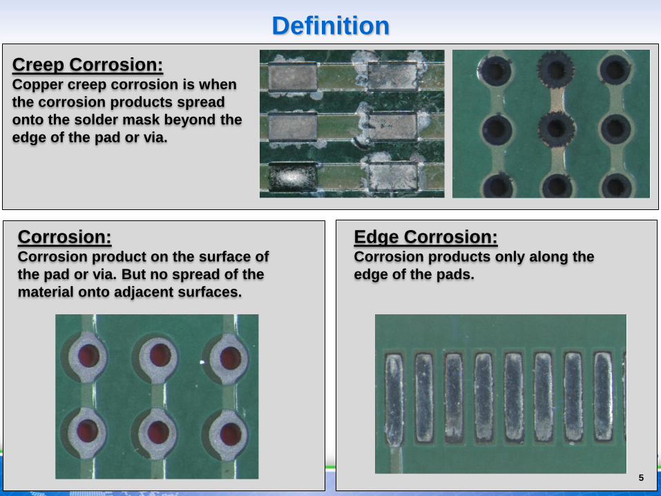
Edge Corrosion: Corrosion products only along the
edge of the pads.
Definition
5
Creep Corrosion: Copper creep corrosion is when
the corrosion products spread
onto the solder mask beyond the
edge of the pad or via.
Corrosion: Corrosion product on the surface of
the pad or via. But no spread of the
material onto adjacent surfaces.

Phase 1 Survey- Creep corrosion
• Creep Corrosion Survey released in Dec 2009.
• 4 different product types were surveyed.
• 45 respondents and 67% of them have seen creep corrosion
failures.
6
0 2 4 6 8 10 12
Consumer
Comput er s and
Per i pher al s
Tel ecom and Hi gh End
Ser ver s
I ndust r i al and
Aut omot i ve -
Passenger Compar t ment
Bar chart with number of
respondents which meet
creep corrosion failure for
each product type.

Phase 1 Survey- Creep corrosion-The life to failure
Q: Please provide the average service time to failure for this product
due to creep corrosion?
• 31 available answers.
• The life to failure is less than 5 years, in most of the cases (about
90%) less than 3 years.
• These are designed for 5-10 years of the average life, Clearly creep
corrosion results in early field failures.
7
0
2
4
6
8
10
12
14
<1 y
ear
1-3
year
s
3-5
year
s
>5 y
ear s
I ndust r i al
Tel ecom
Comput er
Consumer
Co
un
ts o
f th
e s
ele
cti
on
7
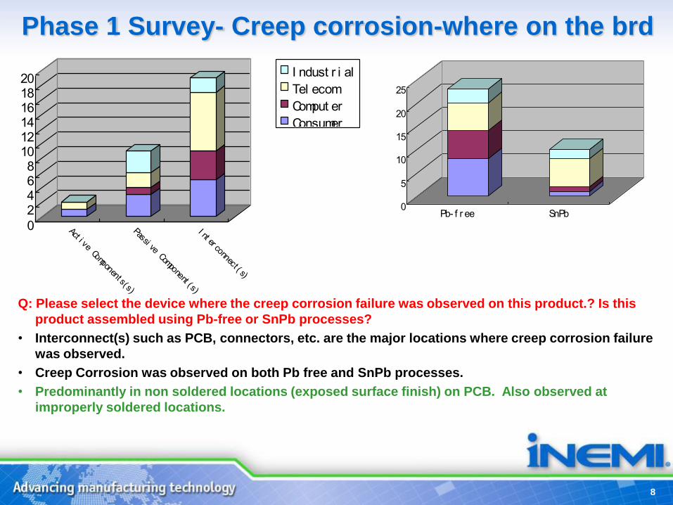
Phase 1 Survey- Creep corrosion-where on the brd
0
2468
101214161820
Act i ve Component s(s)
Passi ve Component (s)
I nt er connect ( s)
I ndust r i al
Tel ecom
Comput er
Consumer
0
5
10
15
20
25
Pb- f r ee SnPb
Q: Please select the device where the creep corrosion failure was observed on this product.? Is this
product assembled using Pb-free or SnPb processes?
• Interconnect(s) such as PCB, connectors, etc. are the major locations where creep corrosion failure
was observed.
• Creep Corrosion was observed on both Pb free and SnPb processes.
• Predominantly in non soldered locations (exposed surface finish) on PCB. Also observed at
improperly soldered locations.
8
Phase 1 Survey- Creep corrosion- Summary
• Creep corrosion is a common failure mode in various product types (from
consumer, computer to telecom and industrial applications).
• Most of the creep corrosion failures are less than 3 years in field, and the
electrical short is the major failure signature.
• Failures are reported globally. Large number of responses correlated to air
pollution levels/industrial areas. Some reported failures from indoor office area.
Few of the respondents correlated failures with high sulfur environments.
• Typical failure locations are the exposed PCB surface finish areas on the
motherboard. Also those regions that were improperly soldered/touched up
showed corrosion. Corrosion of silver terminals on passive components was
also reported. Seen both on Pb-Free and Sn-Pb assembly processes.
• ImAg surface finish was most frequently reported for creep corrosion. Failures
observed on PCB’s with OSP surface finish in harsh environments.
• None of the failures were induced by overly aggressive design features.
9

Technical findings from Telephonic Interviews
• All the respondents agree that it is an environmentally
driven problem.
– Presence of Sulfur, humidity have been mainly attributed for all the problems.
– The role played by flux is unclear.
• Some of the respondents(4/8) mentioned there is no role played by flux/residue in the failures. However few (4/8) of the respondents acknowledged that aggressive fluxes could accelerate the reactions.
– No clarity on the role of rework and related process parameters
– No standard test method to evaluate creep corrosion. Standard MFG unable to recreate creep on consistent basis. Clay test and modified MFG are being experimented with.
10

Phase 2 - Factors discussed
• Failure mechanism study
– Temperature
– Contaminant concentration
– Humidity
– Surface finish
– Flux
– Voltage impact?
– Air flow
– Assembly – thermal profile
– Rework
– Soldermask geometry
– Soldermask material, surface (matte, glossy)
• Mitigation method study
– Conformal coating
– Over spray chemicals to isolate the circuitry
– Carbon pack (local to the equipment) to filter
air at the inlet
– Fill vias/cover with soldermask (still need test
points, there may be alternatives)
– Surface finish
• Test method study
– clay test (used by Dell, Alcatel-Lucent)
– modified MFG test (IPC 3-11g)
– Something new? Or team up with others?
• Environment monitoring and control (clean
the air)
– ASHRAE
– LBNL (failure rate vs. environment)
• Acceleration study to bridge environment
to product life
11
Phase 3: Investigation of Factors That Influence
Creep Corrosion
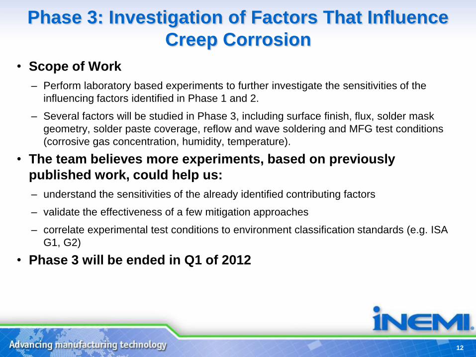
• Scope of Work
– Perform laboratory based experiments to further investigate the sensitivities of the
influencing factors identified in Phase 1 and 2.
– Several factors will be studied in Phase 3, including surface finish, flux, solder mask
geometry, solder paste coverage, reflow and wave soldering and MFG test conditions
(corrosive gas concentration, humidity, temperature).
• The team believes more experiments, based on previously
published work, could help us:
– understand the sensitivities of the already identified contributing factors
– validate the effectiveness of a few mitigation approaches
– correlate experimental test conditions to environment classification standards (e.g. ISA
G1, G2)
• Phase 3 will be ended in Q1 of 2012
12

Experimental Plan
13
Chamber Uniformity
Test (3 runs)
Formal MFG Test
(3 runs planned)
H2S = 1700 ppb; NO2 = 200 ppb; Cl2 = 20 ppb;
SO2 = 200 ppb; 40℃, RH 70-75%, 5 days
H2S = 500 ppb; NO2 = 200 ppb; Cl2 = 20 ppb;
SO2 = 200 ppb; 40℃, RH 70-75%, 5 days
H2S = 1000 ppb; NO2 = 200 ppb; Cl2 = 20 ppb;
SO2 = 200 ppb; 40℃, RH 70-75%, 5 days
H2S = 1200 ppb; NO2 = 200 ppb; Cl2 = 20 ppb;
SO2 = 200 ppb; 40℃, RH 70-75%, 20 days
H2S = 1200 ppb; NO2 = 200 ppb; Cl2 = 20 ppb;
SO2 = 200 ppb; 40℃, RH 70-75%, 20 days
H2S = 1200 ppb; NO2 = 200 ppb; Cl2 = 20 ppb;
SO2 = 200 ppb; 40℃, RH 70-75%, 20 daysTo be determined
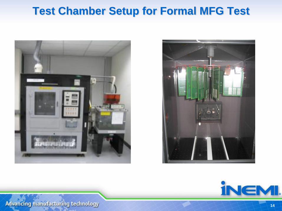
Test Chamber Setup for Formal MFG Test
14

Corrosion Product ThicknessWeight Gain vs. Coulometric Reduction
Ag 2 Ag 3 Ag4 Ag 5 Ag 6
Ag2S
wt gain, angstroms630 910 580 1170 720
Ag2S
coulometeric reduction,
angstroms
513 538 535 546 636
Cu 2 Cu 3 Cu 4 Cu 5 Cu 6 Cu 7 Cu 8
Cu corrosion product
thickness
wt gain, angstroms
17410 15880 15630 15060 17840 17790 18990
Cu2S
Coulometeric reduction,
angstroms
-- 14603 20361 14127 20574 16574 22181
15

Corrosion Product – Cu Coupon
Spectrum In stats. C O S Cu Total
Spectrum 1 Yes 30.99 6.78 11.09 51.14 100.00
Spectrum 2 Yes 2.50 19.06 78.45 100.00
Spectrum 3 Yes 14.99 8.35 2.94 73.72 100.00
Spectrum 4 Yes 100.00 100.00
Max. 30.99 8.35 19.06 100.00
Min. 14.99 2.50 2.94 51.14
All results in weight%
Cu coupon Cu coupon
Corrosion Product
Corrosion Product
16
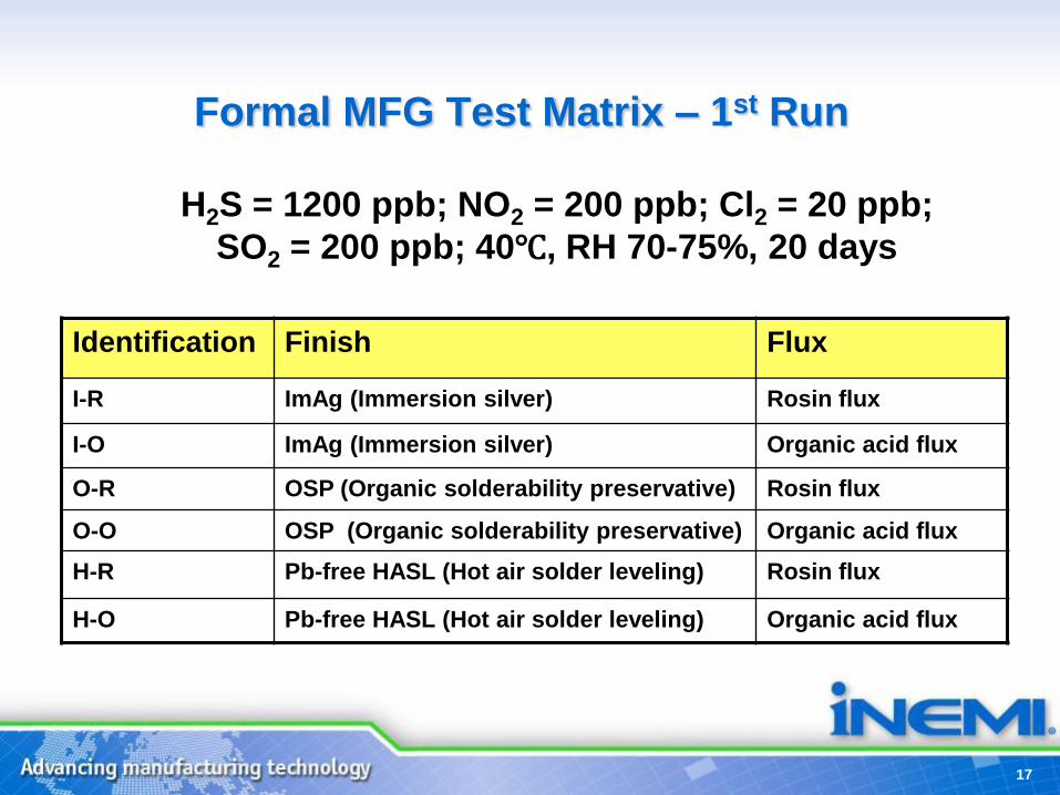
Formal MFG Test Matrix – 1st Run
H2S = 1200 ppb; NO2 = 200 ppb; Cl2 = 20 ppb;
SO2 = 200 ppb; 40℃, RH 70-75%, 20 days
17
Identification Finish Flux
I-R ImAg (Immersion silver) Rosin flux
I-O ImAg (Immersion silver) Organic acid flux
O-R OSP (Organic solderability preservative) Rosin flux
O-O OSP (Organic solderability preservative) Organic acid flux
H-R Pb-free HASL (Hot air solder leveling) Rosin flux
H-O Pb-free HASL (Hot air solder leveling) Organic acid flux
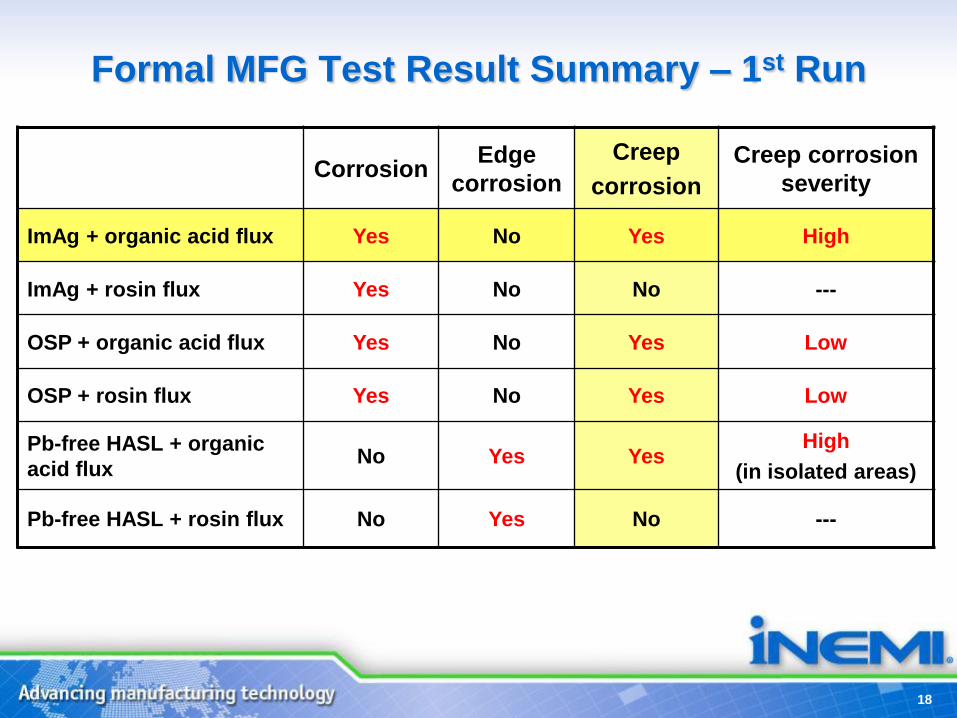
Formal MFG Test Result Summary – 1st Run
CorrosionEdge
corrosion
Creep
corrosion
Creep corrosion
severity
ImAg + organic acid flux Yes No Yes High
ImAg + rosin flux Yes No No ---
OSP + organic acid flux Yes No Yes Low
OSP + rosin flux Yes No Yes Low
Pb-free HASL + organic
acid fluxNo Yes Yes
High
(in isolated areas)
Pb-free HASL + rosin flux No Yes No ---
18
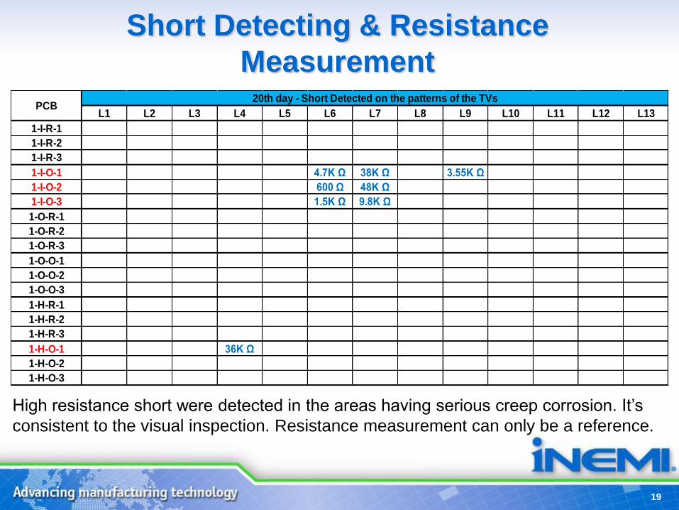
Short Detecting & Resistance
Measurement
L1 L2 L3 L4 L5 L6 L7 L8 L9 L10 L11 L12 L13
1-I-R-1
1-I-R-2
1-I-R-3
1-I-O-1 4.7K Ω 38K Ω 3.55K Ω
1-I-O-2 600 Ω 48K Ω
1-I-O-3 1.5K Ω 9.8K Ω
1-O-R-1
1-O-R-2
1-O-R-3
1-O-O-1
1-O-O-2
1-O-O-3
1-H-R-1
1-H-R-2
1-H-R-3
1-H-O-1 36K Ω
1-H-O-2
1-H-O-3
PCB20th day - Short Detected on the patterns of the TVs
High resistance short were detected in the areas having serious creep corrosion. It’s
consistent to the visual inspection. Resistance measurement can only be a reference.
19

ImAg After 20 Days MFG Testing
Bottom Side
1-I-O-11-I-R-1
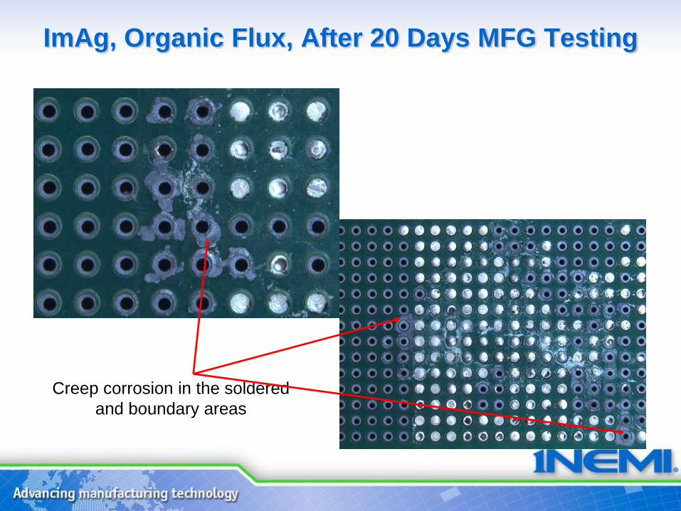
ImAg, Organic Flux, After 20 Days MFG Testing
Creep corrosion in the soldered
and boundary areas
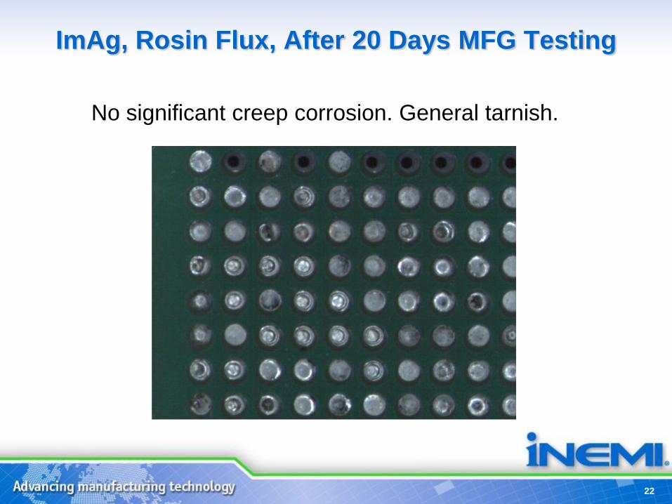
ImAg, Rosin Flux, After 20 Days MFG Testing
22
No significant creep corrosion. General tarnish.
23
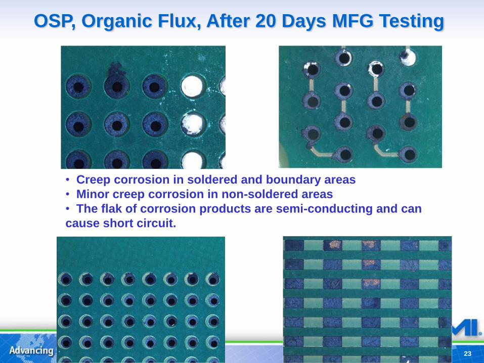
• Creep corrosion in soldered and boundary areas
• Minor creep corrosion in non-soldered areas
• The flak of corrosion products are semi-conducting and can
cause short circuit.
OSP, Organic Flux, After 20 Days MFG Testing

24
OSP, Rosin Flux, After 20 Days MFG Testing
Minor creep corrosion, non solder or flux location
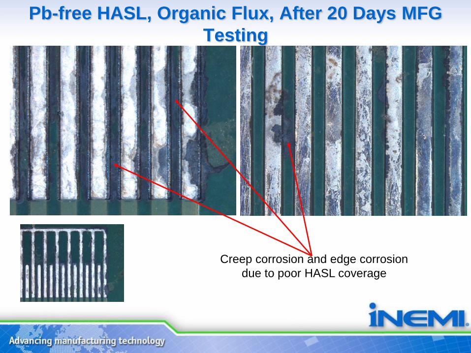
Pb-free HASL, Organic Flux, After 20 Days MFG
Testing
Creep corrosion and edge corrosion
due to poor HASL coverage
26
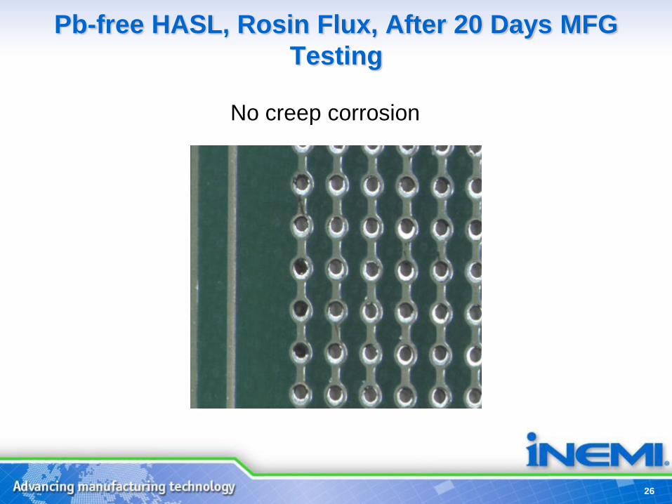
Pb-free HASL, Rosin Flux, After 20 Days MFG
Testing
No creep corrosion

Summary
• MFG test condition of the 1st formal run is chosen to reach the
target of about 500nm/day corrosion rate on Cu coupons.
• Observed from the test Creep Corrosion, Corrosion, Edge
Corrosion on the test boards. Electrical short were detected.
• Observed creep corrosion with all the finish types tested
(ImAg, OSP, Pb-free HASL), however more creep corrosion
occurred on boards with organic acid flux.
• Most severe creep corrosion was observed on ImAg boards
with organic acid flux.
• Most serious creep corrosion locations have obvious flux
residue. Most creep corrosion happened in soldered boundary
area.
• Investigations are planned to evaluate issues identified in 1st
formal run.
27


![LONG TERM TESTS FOR CREEP OF LAMINATED ...tests. These produced the result that the two year creep tests have negligible influence on the hysteresis of the laminated rubber bearing[2].](https://static.fdocuments.net/doc/165x107/60ee797798b9614041115f0c/long-term-tests-for-creep-of-laminated-tests-these-produced-the-result-that.jpg)

