INVESTIGATION OF DRILLING PERFORMANCE IN CRYOGENIC ...
129
University of Kentucky University of Kentucky UKnowledge UKnowledge Theses and Dissertations--Mechanical Engineering Mechanical Engineering 2014 INVESTIGATION OF DRILLING PERFORMANCE IN CRYOGENIC INVESTIGATION OF DRILLING PERFORMANCE IN CRYOGENIC DRILLING ON CFRP COMPOSITE LAMINATES DRILLING ON CFRP COMPOSITE LAMINATES Tian Xia Universtiy of Kentucky, [email protected] Right click to open a feedback form in a new tab to let us know how this document benefits you. Right click to open a feedback form in a new tab to let us know how this document benefits you. Recommended Citation Recommended Citation Xia, Tian, "INVESTIGATION OF DRILLING PERFORMANCE IN CRYOGENIC DRILLING ON CFRP COMPOSITE LAMINATES" (2014). Theses and Dissertations--Mechanical Engineering. 36. https://uknowledge.uky.edu/me_etds/36 This Master's Thesis is brought to you for free and open access by the Mechanical Engineering at UKnowledge. It has been accepted for inclusion in Theses and Dissertations--Mechanical Engineering by an authorized administrator of UKnowledge. For more information, please contact [email protected].
Transcript of INVESTIGATION OF DRILLING PERFORMANCE IN CRYOGENIC ...

University of Kentucky University of Kentucky
UKnowledge UKnowledge
Theses and Dissertations--Mechanical Engineering Mechanical Engineering
2014
INVESTIGATION OF DRILLING PERFORMANCE IN CRYOGENIC INVESTIGATION OF DRILLING PERFORMANCE IN CRYOGENIC
DRILLING ON CFRP COMPOSITE LAMINATES DRILLING ON CFRP COMPOSITE LAMINATES
Tian Xia Universtiy of Kentucky, [email protected]
Right click to open a feedback form in a new tab to let us know how this document benefits you. Right click to open a feedback form in a new tab to let us know how this document benefits you.
Recommended Citation Recommended Citation Xia, Tian, "INVESTIGATION OF DRILLING PERFORMANCE IN CRYOGENIC DRILLING ON CFRP COMPOSITE LAMINATES" (2014). Theses and Dissertations--Mechanical Engineering. 36. https://uknowledge.uky.edu/me_etds/36
This Master's Thesis is brought to you for free and open access by the Mechanical Engineering at UKnowledge. It has been accepted for inclusion in Theses and Dissertations--Mechanical Engineering by an authorized administrator of UKnowledge. For more information, please contact [email protected].

STUDENT AGREEMENT: STUDENT AGREEMENT:
I represent that my thesis or dissertation and abstract are my original work. Proper attribution
has been given to all outside sources. I understand that I am solely responsible for obtaining
any needed copyright permissions. I have obtained needed written permission statement(s)
from the owner(s) of each third-party copyrighted matter to be included in my work, allowing
electronic distribution (if such use is not permitted by the fair use doctrine) which will be
submitted to UKnowledge as Additional File.
I hereby grant to The University of Kentucky and its agents the irrevocable, non-exclusive, and
royalty-free license to archive and make accessible my work in whole or in part in all forms of
media, now or hereafter known. I agree that the document mentioned above may be made
available immediately for worldwide access unless an embargo applies.
I retain all other ownership rights to the copyright of my work. I also retain the right to use in
future works (such as articles or books) all or part of my work. I understand that I am free to
register the copyright to my work.
REVIEW, APPROVAL AND ACCEPTANCE REVIEW, APPROVAL AND ACCEPTANCE
The document mentioned above has been reviewed and accepted by the student’s advisor, on
behalf of the advisory committee, and by the Director of Graduate Studies (DGS), on behalf of
the program; we verify that this is the final, approved version of the student’s thesis including all
changes required by the advisory committee. The undersigned agree to abide by the statements
above.
Tian Xia, Student
Dr. Ibrahim S. Jawahir, Major Professor
Dr. James M. McDonough, Director of Graduate Studies

INVESTIGATION OF DRILLING PERFORMANCE IN CRYOGENIC DRILLING ON CFRP COMPOSITE LAMINATES
THESIS
A thesis submitted in partial fulfillment of the requirements for the degree of Master of Science in
Mechanical Engineering in the College of Engineering at the University of Kentucky
By
Tian Xia
Lexington, Kentucky
Director: Dr. I. S. Jawahir, Professor of Mechanical Engineering
Lexington, Kentucky
2014
Copyright © Tian Xia 2014

ABSTRACT OF THESIS
INVESTIGATION OF DRILLING PERFORMANCE IN CRYOGENIC DRILLING ON CFRP COMPOSITE LAMINATES
In recent years, there has been a substantial growth in the application of carbon fiber reinforced plastic (CFRP) composite materials in automobile and aerospace industries due to their superior properties such as lightweight, high strength, excellent corrosion resistance, and minimal fatigue concerns. The present study evaluates the drilling performance of woven carbon fiber reinforced plastics under both dry and cryogenic cooling conditions using uncoated solid carbide drill with a through-hole for coolant application.
The effects of the cooling conditions and the cutting parameters on drilling performance in drilling CFRP were evaluated in terms of generated thrust force, torque, cutting edge radius, outer corner flank wear, hole quality (including surface roughness, diameter error, roundness, delamination, burr formation, sub-surface quality). Both cooling conditions and cutting parameters were found to influence the thrust force and torque at different levels. The thrust force and the torque are higher in cryogenic cooling under all cutting parameters. In most of the cases, cryogenic drilling gives better bore-hole quality with lower surface roughness, more accurate diameter, less burr generation, better sub-surface quality, etc. Also, the tool-wear rates measured in drilling shows that cryogenic drilling produces less tool-wear than dry drilling does.
KEYWORDS: CFRP, Cryogenic drilling, Hole quality, Tool-wear, Thrust force
Tian Xia
04/22/2014

INVESTIGATION OF DRILLING PERFORMANCE IN CRYOGENIC DRILLING ON CFRP COMPOSITE LAMINATES
By
Tian Xia
I. S. Jawahir
Director of Thesis J. M. McDonough
Director of Graduate Studies
05/06/2014

iii
ACKNOWLEDGEMENTS
I would like to express my sincere gratitude for my advisor, Dr. I. S. Jawahir,
without whose continuous instruction and guidance it would have been impossible for me
to carry out the experiments or finish this thesis. Also, many thanks to Dr. Fazleena
Badurdeen and Dr. Keith Rouch, who kindly agreed to sit on my thesis committee.
Also, I am most grateful to our Lab Manager, Charles Arvin. Many times have I
troubled Charles for instructions for using the machines in our labs, and he was always
ready to offer me the training and the most constructive suggestions and advice. Without
him, I could not have finished my experiments in so smooth a manner.
Equally helpful are my fellow machining research group members, who shared
with me their experiences in coursework, as well as in lab issues. Some of them are close
friends, too. They supported me whenever I had any questions about my studies or
everyday life.
Last but not least, I would like to thank my family, who were always there for me,
whether I have ups or downs during my Master’s studies. To my parents I owe every
moment of happiness, trust, and love in my life—they never cease to believe in me, and
always respond to my needs in every aspect, and in timely manner. I hereby also thank
my wife, who saw me through my days working on this work, and helped me edit and
proofread the chapters. They let me realize that family always is the priority of life.

iv
Table of Contents ACKNOWLEDGEMENTS ............................................................................................... iii
List of Tables ..................................................................................................................... vi
List of Figures ................................................................................................................... vii
CHAPTER 1: INTRODUCTION ....................................................................................... 1
CHAPTER 2: LITERATURE REVIEW ON DRILLING OF CFRP MATERIALS......... 6
2.1 Current Issues in the Drilling of CFRP Composite Materials .......................... 6
2.2 Analysis of Delamination ................................................................................. 8
2.3 Cutting Tool Selection and Tool-wear Measurements ................................... 13
2.4 Cutting Parameter Selection ........................................................................... 21
2.5 Cooling Conditions ......................................................................................... 23
2.6 Cutting Temperature Measurements ............................................................... 28
2.7 Hole Quality and Surface Integrity ................................................................. 28
2.8 Analytical Models ........................................................................................... 31
2.9 Critical Analysis .............................................................................................. 36
2.10 Summary ....................................................................................................... 37
CHAPTER 3: EXPERIMENTAL SETUP AND PROCEDURE ..................................... 39
3.1 Experimental Setup and Cutting Conditions ................................................... 40
3.2 Cutting Tool and Workpiece Materials ........................................................... 42
3.3 Dynamometer and Data Acquisition System .................................................. 43
3.4 Cooling Technique for Cryogenic Drilling of the CFRP Laminates .............. 46
3.5 Borehole Surface Integrity Inspection and Borehole Quality Assessment ..... 47
CHAPTER 4: RESULTS AND DISCUSSION ON TOOL-WEAR, THRUST FORCE AND TORQUE.......................................................................................................... 51
v
4.1 Effects of Cryogenic Cooling on Tool-wear................................................... 52
4.1.1 Cutting edge radius .................................................................................... 52
4.1.2 Outer corner wear ...................................................................................... 60
4.2 Effects of Cryogenic Cooling on Thrust Force and Torque ........................... 64
4.2.1 Thrust force ................................................................................................ 65
4.2.2 Torque ........................................................................................................ 70
4.3 Analytical Model for Critical Thrust Force .................................................... 72
4.4 Summary ......................................................................................................... 76
CHAPTER 5: HOLE QUALITY AND SURFACE INTEGRITY IN DRILLING OF CFRP MATERIALS .................................................................................................. 79
5.1 Introduction ..................................................................................................... 79
5.2 Delamination ................................................................................................... 79
5.3 Burr Generation ............................................................................................... 92
5.4 Analysis of Borehole Sub-surface Damage in Drilling of CFRP Materials ... 94
5.5 Surface Roughness ........................................................................................ 101
5.6 Diameter Error .............................................................................................. 102
5.7 Summary ....................................................................................................... 104
CHAPTER 6: CONCLUSIONS AND FUTURE WORK .............................................. 106
6.1 Summary of Present Work .......................................................................... 106
6.2 Future Work ................................................................................................ 108
REFERENCES ............................................................................................................... 109
VITA ............................................................................................................................... 115

vi
List of Tables
Table 2.1: General evaluation of drilling of CFRP materials ........................................... 37
Table 3.1: Experiment matrix for drilling under different cooling methods .................... 40
Table 5.1: Experiment matrix for drilling under different cooling methods .................... 89
vii
List of Figures
Figure 2.1: Attempted correlations between cutting conditions and quality issues in drilling of CFRP materials. ................................................................................ 8
Figure 2.2: Peel-up and Push-down delamination [8]. ....................................................... 9
Figure 2.3: Correlation between measured thrust force and feed rate during drilling [17]. .......................................................................................................................... 12
Figure 2.4: Thrust force versus number of holes drilled, 2720 rpm and 0.028 mm/rev [25]. .......................................................................................................................... 15
Figure 2.5: Effects of pilot hole on thrust forces (drill diameter, 10 mm; ξ = 0.15 and 0.2) [27]. .................................................................................................................. 17
Figure 2.6: Delamination at the hole exit depending on cutting edge radius. [5]. ............ 18
Figure 2.7: Development of (a) hole entry delamination and (b) hole exit delamination with increasing drilling thrust due to wear [8]. ................................................ 19
Figure 2.8: Cutting edge rounding (a) progression and its correlation with (b) thrust and (c) torque [8]. .................................................................................................... 19
Figure 2.9: Burr height versus cutting time for different feed rates at V = 85 m/min [31]. .......................................................................................................................... 21
Figure 2.10: Tool-life in terms of number of drilled holes (*tests experienced tool fracture) [35]. .................................................................................................................. 22
Figure 2.11: Hole diameter results for the first and last holes drilled in all material sections [35]. .................................................................................................... 25
Figure 2.12: Roundness measurement results [35]. .......................................................... 25
Figure 2.13: Delamination factor against hole number at low feed low speed machining conditions for four different workpiece temperatures [39]. ............................. 27
Figure 2.14: Diameter variation as a result of tool heating [6]. ........................................ 31
Figure 2.15: Micrographs of CFRP borehole surface layers for two process conditions generated by conventional drilling [4]. ............................................................ 31

viii
Figure 2.16: Circular plate model for delamination analysis [47]. ................................... 33
Figure 2.17: Plot of the function [49]. .............................................................................. 35
Figure 3.1: Schematic diagram of measurements and instruments selection. .................. 39
Figure 3.2: (a) Experimental setup of the drilling device; (b) HAAS VF-0 CNC vertical milling center. ................................................................................................... 41
Figure 3.3: Sandvik CoroDrill 860 drill bit. ..................................................................... 42
Figure 3.4: Workpiece material. ....................................................................................... 43
Figure 3.5: (a) Dimensions of dynamometer Type 9772; (b) pictorial view of dynamometer; (c) specially designed tool holder. ............................................ 45
Figure 3.6: Data acquisition system and charge amplifiers. ............................................. 46
Figure 3.7: Liquid nitrogen tank and hose. ....................................................................... 47
Figure 3.8: TESA Micro-Hite 3D CMM. ......................................................................... 50
Figure 3.9: Zygo NewView™ 7300 White Light Interferometer. .................................... 50
Figure 4.1: Cutting edge rounding: (a) Sharp cutting edge (b) Blunt smoothly worn, rounded cutting edge [8]................................................................................... 54
Figure 4.2: Measuring cutting edge radius using Zygo New View 5300 White Light Interferometer. .................................................................................................. 54
Figure 4.3: Typical oblique plots of edge radius measurement of drill bits at f = 0.025 mm/rev and V = 40 m/min after 50 drillings: (a) under cryogenic cooling method, cutting edge radius = 26.1 μm; (b) under dry cooling method, cutting edge radius = 39.4 μm. ..................................................................................... 55
Figure 4.4: Cutting edge rounding progression at: (a) f = 0.025 mm/rev and V = 40 m/min; (b) f = 0.05 mm/rev and V = 40 m/min. ........................................................... 58
Figure 4.5: Cutting edge rounding progression at: (a) f = 0.025 mm/rev and V = 60 m/min; (b) f = 0.05 mm/rev and V = 60 m/min. ........................................................... 59
Figure 4.6: Method of measuring outer corner wear [30]................................................. 62

ix
Figure 4.7: Cutting edge rounding progression at f = 0.05 mm/rev and V = 60 m/min. ... 62
Figure 4.8: Cutting edge rounding progression at f = 0.05 mm/rev and V = 60 m/min. ... 63
Figure 4.9: Outer corner wear progression at f = 0.025 mm/rev and V = 60 m/min. ........ 64
Figure 4.10: Outer corner wear progression at f = 0.05 mm/rev and V = 60 m/min. ........ 64
Figure 4.11: Average maximum thrust force at: (a) f = 0.025 mm/rev, V = 40 m/min; (b) f = 0.05 mm/rev, V = 40 m/min; (c) f = 0.025 mm/rev, V = 60 m/min; and (d) f = 0.05 mm/rev, V = 60 m/min; ................................................................. 67
Figure 4.12: Thrust force progression at f = 0.025 mm/rev, V = 60 m/min. ..................... 69
Figure 4.13: Correlation between thrust force cutting and edge radius at f = 0.025 mm/rev, V = 60 m/min. ................................................................................................... 69
Figure 4.14: Average maximum torque at: (a) f = 0.025 mm/rev, V = 40 m/min; (b) f = 0.05 mm/rev, V = 40 m/min; (c) f = 0.025 mm/rev, V = 60 m/min; and (d) f = 0.05 mm/rev, V = 60 m/min; ................................................................. 71
Figure 4.15: Torque progression at f = 0.025 mm/rev, V = 60 m/min. ............................. 72
Figure 4.16: Correlation between torque cutting and edge radius at f = 0.025 mm/rev, V = 60 m/min. ................................................................................................... 72
Figure 4.17: Circular plate model for delamination analysis (twist drill) [45]. ................ 74
Figure 5.1: Demonstration of 𝐷0 and 𝐷𝑚𝑎𝑥. ................................................................. 80
Figure 5.2: Optical images of first and last hole of CFRP materials drilled at V = 60 m/min, f = 0.025 mm/rev, under: (a) dry condition; (b) cryogenic conditions. .......................................................................................................................... 82
Figure 5.3: Average delamination of boreholes of CFRP materials drilled at different cutting speeds and feed rates: (a) V = 40 m/min, f = 0.025 mm/rev; (b) V = 40 m/min, f = 0.05 mm/rev; (c) V = 60 m/min, f = 0.025 mm/rev; and (d) V = 60 m/min, f = 0.05 mm/rev. ................................................................................... 84
Figure 5.4: Delamination progression at V = 40 m/min, f = 0.05 mm/rev. ...................... 85
Figure 5.5: Delamination progression at V = 40 m/min, f = 0.25 mm/rev. ...................... 85

x
Figure 5.6: Delamination progression at V = 60 m/min, f = 0.05 mm/rev. ...................... 86
Figure 5.7: Delamination progression at V = 60 m/min, f = 0.025 mm/rev. .................... 86
Figure 5.8: Delamination progression with cutting edge radius at V = 60 m/min, f = 0.025 mm/rev. ............................................................................................. 87
Figure 5.9: Delamination progression with thrust force at V = 60 m/min, f = 0.025 mm/rev. ............................................................................................. 87
Figure 5.10: Back-up materials and preparation of samples with back-up materials. ...... 88
Figure 5.11: Last hole with and without back-up support under: (a) cryogenic cooling condition; (b) dry condition. ............................................................................. 91
Figure 5.12: Average delamination factor for samples with and without back-up support. .......................................................................................................................... 92
Figure 5.13: Burr generation for: (a) Hole number 30; (b) Hole number 40; and (c) Hole number 50. ........................................................................................................ 93
Figure 5.14: Information of workpiece: (a) 2x2 twill pattern [32]; (b) quasi-isotropic lay-up. ................................................................................ 95
Figure 5.15: Cross-section image of samples. .................................................................. 96
Figure 5.16: carbon fiber with direction of: (a) 0°; (b) -45°/ 45°; (c) 90°. ....................... 97
Figure 5.17: Cross-section image of samples machined at f = 0.05 mm/rev and V = 60 m/min under cryogenic and dry cooling methods. ........................................... 98
Figure 5.18: Cross-section image of hole at f = 0.05 mm/rev and V = 40 m/min under cryogenic cooling. ............................................................................................ 99
Figure 5.19: Cross-section image of hole at f = 0.05 mm/rev and V = 40 m/min under cryogenic cooling: (a) Hole No 10; (b) Hole No 50. ...................................... 100
Figure 5.20: Average surface roughness (Ra) for tests at: Figure 4.11: Average maximum thrust force at: (a) f = 0.025 mm/rev, V = 40 m/min; (b) f = 0.05 mm/rev, V = 40 m/min; (c) f = 0.025 mm/rev, V = 60 m/min; and (d) f = 0.05 mm/rev, V = 60 m/min; .......................................................................... 102

xi
Figure 5.21: Diameter of boreholes at V = 60 m/min, f = 0.05 mm/rev, dry cooling condition. ........................................................................................................ 103
Figure 5.22: Diameter of boreholes at V = 60 m/min, f = 0.05 mm/rev, cryogenic cooling condition. ........................................................................................................ 104

1
CHAPTER 1: INTRODUCTION
Composite materials form a material system composed of a mixture or a
combination of two or more macro constituents that differ in form and chemical
composition. They are developed specifically to meet the challenge of modern industry
[1]. In recent years, there has been a substantial growth in the application of carbon fiber
reinforced plastic (CFRP) composite materials in automobile and aerospace areas due to
their superior properties such as lightweight, high strength, excellent corrosion resistance,
and minimal fatigue concerns.
Among all manufacturing processes, hole-making operations are essential for the
functionality of machined components. The use of CFRP (carbon fiber reinforced
plastics) frequently involves drilling of a large number of holes for structural joints. For
example, over 100,000 holes are made for a small single engine aircraft [2]; in a large
transport aircraft millions of holes are made, mostly for fasteners such as rivets, bolts and
nuts [2]. In these cases, drilling becomes one of the most widely needed operations in
machining of CFRP composite laminates.
However, problems exist, such as high rejection ratio of the product and severe
tool-wear usually due to the mechanical and thermal properties of this fiber- reinforced
material. The abrasive nature of CFRP material often leads to a high tool-wear rate and
some related defects such as delamination; cutting temperature is an another problem

2
that causes defects due to the low thermal conductivity of this material. Many factors
influence the borehole quality, which can lead to rejection of the products. These factors
are cutting parameters, type of cutting tools and cooling conditions, etc. [3].
Achieving a lower thrust force is the first priority during drilling process since
thrust force is highly related to delamination. Delamination is a mode of failure, which
happens in drilling of laminate material, and when thrust force exceeds a certain value, it
would cause layers of multilayer material such as CFRP to become separated. This
failure would cause the material a significant loss of mechanical toughness, and would
extremely diminish inter-laminar strength. Avoiding delamination becomes the main
objective of drilling CFRP material since the CFRP material continues to grow in the
aerospace and automobile industries, and the safety issue has become the most cared-for
aspect. Structures and parts with delamination would very likely reduce the reliability of
the product and endanger the safety of the passengers. The optimum cutting parameters
should be determined in order to reach a lower thrust force, and for achieving a
delamination-free borehole. A relatively low feed rate (lower than 0.1 mm/rev) and a
high cutting speed (lager than 800 rpm) are recommended for drilling CFRP material [3].
On the other hand, thermally-induced damage is another aspect of defect that
cannot be ignored. Low thermal conductivity of CFRP would lead to an extremely high
cutting temperature and make the expansion of the drill bit, which would influence the
dimensional accuracy of the boreholes. Also, degradation would occur in matrix due to
3
the high temperature. Traditionally there are two cooling conditions for use, i.e., dry and
flood cooling, and recently the usage of MQL (minimum quantity lubrication) has
emerged. Applying cooling would, to some degree, reduce the cutting temperature, and
then reduce the defect related to thermal damage. But, a chemical reaction might happen
between the coolant liquid and the CFRP material, which would diminish the properties
of the material. This factor should also be considered when drilling CFRP material.
Meanwhile, to the best of our knowledge, the influence of cryogenic cooling in
drilling performance has not yet been studied. High cutting temperatures can negatively
affect the structure of CFRP and the shape of machined surfaces. Applying cryogenic
cooling might significantly influence the hole quality by reducing the cutting temperature,
thus preventing pyrolysis and material-softening, and thermally–induced defects from
happening.
The purpose of this project is to investigate the influences of cryogenic cooling on
drilling CFRP plate. An assumption has been made that the hole quality can be enhanced
by lowering the cutting temperature through cryogenic cooling. Different aspects of the
drilling performance, such as the torque, the thrust force, the hole quality, and the
tool-wear, have been studied under different cutting parameters and cooling conditions.
Besides, analytical models are also used in this project for the purpose of establishing the
relationship between thrust force and delamination.
The innovative part of this thesis lies in the experiment setup: the drilling test is

4
carried out with a fixed drill bit and a rotating cylinder-shaped CFRP composite
specimen, in order to apply cryogenic cooling. Liquid nitrogen goes through the internal
coolant hole of a coolant-fed drill during the drilling operation. During the whole course
of the experiment, the workpiece was processed under dry and cryogenic cooling
conditions. A range of feed rates and cutting speeds are also applied to enable the
optimum conditions for drilling CFRP composites. The rest of this thesis is organized as
follows:
Chapter 2 presents an introduction on drilling carbon fiber reinforced plastics.
Also presented is a review of some of the previous work that has been done in the field.
Chapter 3 presents the experimental setup for machining and the drilling
experiments performed under different cooling conditions: dry and cryogenic cooling. It
also gives a brief description of the specimen preparation method used for drilling test.
Chapter 4 presents trust force and torque results obtained under each cooling
condition at different cutting parameters of cutting speed and feed rate. It also includes
analytical models for drilling CFRP laminates in order to establish a relationship between
the thrust force and delamination. By studying the analytical models, one can have a
better understanding of delamination, one of the most deleterious damage processes
associated with drilling carbon fiber reinforced plastics.
Chapter 5 discusses the surface integrity and delamination results of the machined
samples. The surface integrity parameters such as diameter error, roundness, surface

5
roughness of the internal surface of the borehole and the quality of the internal surface of
the borehole are studied for the specimens.
Chapter 6 presents a summary of findings from this project with a short
discussion on future work.

6
CHAPTER 2: LITERATURE REVIEW ON DRILLING OF CFRP MATERIALS
This chapter begins with an overview of current issues in the drilling of CFRP
materials. Then, several specific aspects involved in the drilling of CFRP materials will
be discussed in detail presenting the current state-of-the-art, and this includes current
knowledge on delamination, thrust force and torque, cutting temperature, cooling
methods, and cutting tool selection in drilling of CFRP materials.
2.1 Current Issues in the Drilling of CFRP Composite Materials
Machining CFRP composite materials raise some specific problems due to their
unique nature of inhomogeneous and anisotropic properties [4]. It has been observed
improper cutting parameters or tool-wear lead to damages such as delamination, cracks,
fiber/matrix debonding, fiber breakage and matrix thermal melting [4]. Since they are
very abrasive, fibers used as reinforcement rapidly increase the tool-wear rate, and
therefore the drill is worn quickly and can no longer maintain the edge sharpness.
Researchers also found that if the cutting edge radius increases to a certain level, the
thrust force will surpass a critical value, when delamination is most likely to happen at
the exit side of the machined surfaces [5]. Not only does tool-wear bring the problem
of delamination, the blunt drill also causes the problem of excessive burr generation.
According to Teti [3], the main reason for burr generation is outer corner wear.

7
Meanwhile, as a consequence of low thermal conductivity of CFRP, the heat generated
during the cutting process could not be effectively transferred. This leads to an
extremely high cutting temperature generation during the machining process, resulting
in more severe expansion of cutting tool diameter during drilling CFRP, compared
with drilling metallic materials. This overheating problem causes matrix material of
carbon fiber reinforced composite to get burned, as well as with a larger deviation on
the diameter of the bored holes [6]. These quality control problems, which severely
and negatively affect the mechanical properties of parts, are the reasons for a
significant rejection rate of machined composite parts [1]. In order to eliminate defects
in drilling CFRP and to achieve boreholes with acceptable hole quality and surface
integrity, many researchers have tried to establish correlations between cutting
conditions and problems occurring during drilling CFRP in order to achieve optimized
results. Figure 2.1 summaries these attempted correlations.

8
Figure 2.1: Attempted correlations between cutting conditions and quality issues in drilling of
CFRP materials.
2.2 Analysis of Delamination
Delamination in the drilling of CFRP composite materials became one of the
major problems for almost all researchers. It is an inter-laminar or inter-ply failure
phenomenon [1]. According to ASTM standard, delamination refers to the separation of
plies in a laminate. This may be local or may cover a large area in the laminate [7]. When
occurring at the top surface around the drilled borehole, it is known as “peel-up
delamination” or “hole entry delamination”. It is more severe at the bottom surface
around the drilled borehole known as “push-out delamination” or “hole exit delamination”
[8]. Hole entry delamination and hole exit delamination are schematically illustrated in
Figure 2. 2.

9
Figure 2.2: Peel-up and Push-down delamination [8].
Delamination has been recognized as the major concern in drilling of CFRP
materials since it induces the structural damage to the laminates and results in poor
assembly tolerance, and thus causes long-term performance deterioration [3]. Ho-Cheng
and Dharan [9] investigated the delamination during drilling in composite laminates. By
using fracture mechanics, they analyzed the problem and found an optimal thrust force as
a function of drilled borehole depth. Their analytical model correlates thrust force to
delamination and they concluded that the maximum thrust force for no delamination can
be used in cutting parameter selection to improve productivity. Analytical models for
drilling carbon fiber reinforced plastics would be discussed in later sections of this thesis.
Several methods have been developed for measuring and evaluating delamination,
of which the ultrasonic C-Scan proves to be the most accurate and precise approach for
quantifying the phenomenon [10]. However, other techniques, such as “dye-penetration”
(DP) testing and “direct visualization” (the usage of a conventional “Tool Makers”
microscope), have also been frequently utilized by various researchers [11]. Khashaba
[12] claims that a precise and economical technique for measuring the delamination

10
resolution has been developed. Equipment required for this technique includes: PC, color
flatbed scanner, and image software (CorelDraw). The drilled specimen is to be placed
directly on the scanner in such a manner that the damage areas in the borehole could be
recorded. This technique is calibrated by measuring several dimensions on a standard
steel ruler. The error lies in the range from 0.3% to 0.8%, which is totally acceptable
when compared with the measurements carried out using the CCD sensor.
Because of the importance of achieving delamination-free or nearly
delamination-free boreholes, researchers have made quite a few attempts. The most
obvious way to reduce delamination is to reduce the feed rate, but it in turn brings
another problem: lower feed rate means lower productivity. Considering that the
recommended highest feed rate for drilling carbon fiber is less than 0.1 mm/rev [13],
which is already a relatively low value for drilling approach, a lower feed rate seems an
unpractical option for industry.
Instead of lowering the feed rate, many authors have come up with ideas of using
different kinds of drill bits in the drilling of CFRP materials. Tsao and Hocheng [14]
investigated the effect of special drill bits on drilling-induced delamination of CFRP
materials. Several specially designed drills including saw drill, candle stick drill, and core
drill were studied. They also compared the theoretical critical thrust force with the
experimental critical force for each type of drill bit [15]. Most of the special drill bits
have a higher critical thrust force than conventional twist drills, which makes them more

11
difficult to cause delamination. Fernandes and Cook [16] studied the effects of drilling
carbon composite using one-shot drills. This specially designed drill bit has two cutting
edges, which allow the drill bit to drill and to ream at the same time. The tip of this drill
has a smaller diameter compared with the rest of the drill, and this design allows the drill
bit to create a pilot hole before achieving the desired diameter, which will reduce the
thrust force. With an extremely thin web of the drill, this drill bit significantly reduces the
thrust force during drilling process, thus contributing to reducing delamination.
Another way to solve delamination is using back-up materials. This method has
been widely used in industry. Tsao and Hocheng [17] reported that delamination can be
effectively reduced or even eliminated by using back-up materials to support and
counteract the deflection of the composite laminate, which causes exit side delamination.
They also mention that the use of the back-up materials is very common in practice and it
is extremely effective, but no analytical study has been done regarding this effect. In their
work, they explained it both mathematically and physically. From the analytical
viewpoint, the critical drilling thrust force for material with back up is calculated and
compared with the critical drilling thrust force for material without backup. The results
show that the critical thrust force is higher when a back-up support is applied. The effect
could also be physically explained by the counteraction of back-up material to the
drilling-induced downward bending deflection of the laminate. Although the deflection of
the last layer of the laminate could not be avoided, the back-up material has a much

12
higher stiffness than the single layer being bent, and thus will effectively reduce the
laminate deflection. As seen in Figure 2.3, critical thrust forces for drilling with and
without backup plate were calculated, and it is clear that critical thrust force with back-up
plate is larger, and meanwhile measured thrust force exceeded estimated thrust force for
drilling without a back-up plate. This shows the advantage of using a back-up plate..
Figure 2.3: Correlation between measured thrust force and feed rate during drilling [17].
Another attempt has been made by Shyha et al. [18] to reduce the delamination.
They applied peel ply layers (0.1 mm thick nylon sheet attached on both sides of 3 mm
thick laminates) on hole entry and exit delamination. The hole quality was significantly
improved, because remarkable reduction in damages relating to fiber breakage, matrix
melting, and delamination was observed during the drilling of the nylon-backed CFRP
material. The reason for the improvement in hole quality after applying peel ply layers is
13
that peel ply layers support the CFRP material during the drilling process as back-up
materials. As discussed in the previous section, using back-up material would effectively
reduce or even eliminate delamination.
Another strategy is the use of pilot holes. Won and Dharan [19] conducted a
series of experiments to evaluate thrust force under various feeds, and drilling
experiments were carried out on laminates with and without pilot holes. They
investigated the effects of chisel edge and pilot hole on thrust force. Experimental results
show that thrust force measurements were much smaller when using a smaller chisel edge
and drilling laminates with pilot holes. The results indicate that the thrust force
contribution from the chisel edge is a significant component of the total thrust force,
suggesting that the potential for delamination in composite laminates can be significantly
reduced through the use of pilot holes.
Other strategies such as utilization of non-conventional vibration-assisted drilling
techniques [20], laser machining, ultrasonic machining [21], and active back-up force [22]
have also been used by various researchers in order to reduce or eliminate delamination.
2.3 Cutting Tool Selection and Tool-wear Measurements
Carbon fibers used as reinforcement in the CFRP feature high hardness and
abrasiveness, and therefore the tool materials recommended for cutting CFRP laminates
include carbides (both coated and uncoated) and diamond [23]. However, uncoated

14
carbide is the most commonly used tool material.
High speed steel (HSS) tools are also used in some cases, but they have a lower
heat resistance and a high tool-wear rate. This proves to be the case when drilling FRP
using the high speed steel (HSS) drill. A HSS drill does not possess the same capability
in terms of wear resistance as a carbide drill does. The sharpness of the cutting edge
could only be kept at a certain level until sometimes in drilling practice, and afterwards it
rises rapidly, as does the thrust force. For experimental work, the HSS drill bit may be an
option, but it is not a practical choice for the industry. On the other hand, many
researchers recommend the uncoated cemented carbide drill, since its cutting edge radius
is smaller compared with coated carbide and it has a higher wear resistance compared
with the HSS drill bit. Also, the carbide drill is much more economical than the diamond
tool. Davim and Reis [24], in their experimental work, found that the carbide tool yielded
better results than the HSS drill bit did.
Diamond tools (PCD or CVD) have been gaining popularity over the past few
years because their tool-life equals 10 to 20 times of that of uncoated carbides, even
though diamond tools are much more expensive compared with solid carbide drills. Apart
from extending the tool-life, it also lowers the tool changing frequency, and in turn
increases the productivity. Although tool changing takes less than five minutes, a
disruption of the working process still influences the efficiency, and thus leads to loss of
productivity with increased cost of manufacture. Ramulu et al. [23] investigated drilling
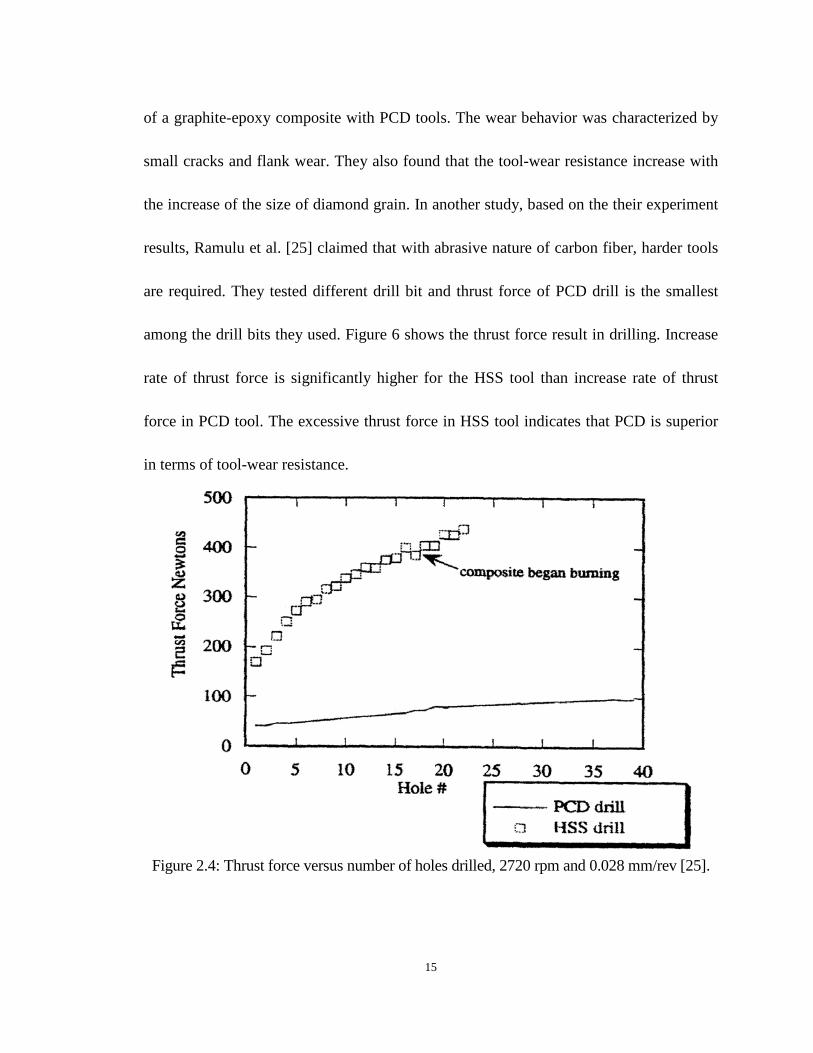
15
of a graphite-epoxy composite with PCD tools. The wear behavior was characterized by
small cracks and flank wear. They also found that the tool-wear resistance increase with
the increase of the size of diamond grain. In another study, based on the their experiment
results, Ramulu et al. [25] claimed that with abrasive nature of carbon fiber, harder tools
are required. They tested different drill bit and thrust force of PCD drill is the smallest
among the drill bits they used. Figure 6 shows the thrust force result in drilling. Increase
rate of thrust force is significantly higher for the HSS tool than increase rate of thrust
force in PCD tool. The excessive thrust force in HSS tool indicates that PCD is superior
in terms of tool-wear resistance.
Figure 2.4: Thrust force versus number of holes drilled, 2720 rpm and 0.028 mm/rev [25].

16
Geometry of the drill bit has a huge impact in the drilling of CFRP. Durão et al.
reported thrust force results from conventional twist drills with different point angle [26].
They found that a drill bit with lower point angle gives lower thrust force, which leads to
a less severe delamination. The numbers of flutes also influences experiment results. In
his study, Davim [24] used three different types of drill bits (diameter of 5mm, 118
degrees point angle): (a) helical flute HSS drill, (b) four-flute K 10 cemented carbide drill,
and (c) helical flute K 10 carbide drill. He reported that the helical flute K 10 drill
produced less damage on the composite laminate than the four-flute carbide (K 10) drill
did in his research. Tsao and Hocheng [27] recommended using drill bits with short
chisel edge length since it would reduce the thrust force effectively. As shown in Figure
2.5, thrust forces were significantly smaller with pilot hole when comparing with thrust
forces without pilot hole at any feed rate, and were lower than the critical thrust force at
the feed rate of 0.15 mm/rev. Shyha et al. [28] reported that productivity in terms of the
number of holes drilled per tool increased significantly (up to 50%) when uncoated
tungsten carbide stepped drills were used at a higher feed rate (0.2 mm/rev rather than 0.1
mm/rev). Stepped drill geometry leads to lower chisel edge/workpiece material
interaction, while the increase in the feed rate reduced the time of drilling operation, thus
reducing the abrasive action and cutting temperature. On the other hand, both
conventional (diameter of 1.5 mm) and stepped drills with TiN coated suffer low tool life
which have resulted from a possible chemical reaction between the CFRP and coating,

17
and also from the lower cutting edge radius of the uncoated drill.
Figure 2.5: Effects of pilot hole on thrust forces (drill diameter, 10 mm; ξ = 0.15 and 0.2) [27].
The cutting edge also has a large influence on the drilling performance in drilling
of fiber reinforced plastics. Franke [5] pointed out that the cutting edge radius influences
the feed force as well as the drilled hole quality. The flank pressure of the tool increases
with the increase of the cutting edge radius. In this case the tool has to generate a larger
force to penetrate the workpiece, which leads to an increase in thrust force. Furthermore,
the increase in the cutting edge radius causes the workpiece material to deform more and
more severely, until it can no longer cut.
The elastically-deformed workpiece matrix material will return to its former shape
when the tool is drawn back from the hole. Therefore, the hole will prove to be
undersized. The borehole diameter is also influenced by the corner radius (also known as
18
the tool nose radius) and the minor cutting edge. The increasing roundness of the corner
and the minor cutting edge of drill bit together lead to a rise in borehole roundness as
well as borehole cylindricity deviation. Fiber separation is impeded as the cutting edge
radius is larger than the fiber diameter. In this case the fibers are deformed rather than
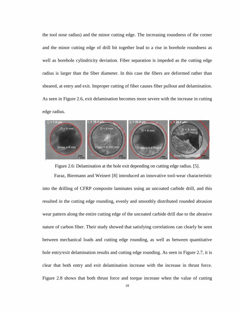
sheared, at entry and exit. Improper cutting of fiber causes fiber pullout and delamination.
As seen in Figure 2.6, exit delamination becomes more severe with the increase in cutting
edge radius.
Figure 2.6: Delamination at the hole exit depending on cutting edge radius. [5].
Faraz, Biermann and Weinert [8] introduced an innovative tool-wear characteristic
into the drilling of CFRP composite laminates using an uncoated carbide drill, and this
resulted in the cutting edge rounding, evenly and smoothly distributed rounded abrasion
wear pattern along the entire cutting edge of the uncoated carbide drill due to the abrasive
nature of carbon fiber. Their study showed that satisfying correlations can clearly be seen
between mechanical loads and cutting edge rounding, as well as between quantitative
hole entry/exit delamination results and cutting edge rounding. As seen in Figure 2.7, it is
clear that both entry and exit delamination increase with the increase in thrust force.
Figure 2.8 shows that both thrust force and torque increase when the value of cutting

19
edge rounding grows. In other words, the increase in cutting edge rounding will
compromise the hole quality in terms of increasing both entry and exit delamination.
Figure 2.7: Development of (a) hole entry delamination and (b) hole exit delamination with
increasing drilling thrust due to wear [8].
Figure 2.8: Cutting edge rounding (a) progression and its correlation with (b) thrust and
(c) torque [8].
20
Another tool-wear criterion brought up by Teti [3] is outer corner flank wear,
which has been claimed to be the main reason for burr generation in drilling fiber
reinforced plastics materials. There are many researchers who have done research on this
tool-wear criterion. Harris et al. [29, 30] defined outer corner wear, and also offered a
method to measure the outer corner flank wear lands via optical microscope. They also
mentioned that using this wear criterion, a drill can be determined as a worn tool when
wear land reached more than 75% of the margin width. Abu-Mahfouz [31] also pointed
out that wear on both outside corners of the drill point is due to high friction (rubbing)
and the impact forces between the drill and the machined hole walls. He suggested that
both feed and cutting speeds influence outer corner wear rate, and outer corner wear is
the main factor for burr generation. As seen in Figure 2.9, burr height increases with the
increase of cutting time, which could be easily explained since drill bits become more
blunt during drilling. It is also noticeable that a higher feed rate, which leads to higher
outer corner wear rate, leads to larger burr generation.

21
Figure 2.9: Burr height versus cutting time for different feed rates at V = 85 m/min [31].
2.4 Cutting Parameter Selection
Owing to the inhomogeneity and anisotropy of CFRP materials, the selection of
cutting parameters plays a very important role. The effects of feed rates and cutting
speeds on resulting torque and thrust force have been widely studied [32]. Feed rate
among all the cutting parameters draws most interest from researchers [33]. Generally
speaking, on one hand a greater feed rate brings in larger productivity. On the other hand,
low value of feed rate ensures low thrust force, thus reducing drilling- induced
delamination. Shyha et al. [34] worked on the effect of laminate configuration and the

22
feed rate on the performance of drilling holes in carbon fibre reinforced plastic
composites. The control variables considered are prepreg type (three types) and form
(unidirectional (UD) and woven), together with the drill feed rate (0.2 and 0.4 mm/rev).
In this case there are a total of 12 combinations to test using tungsten carbide (WC)
stepped drills. The drill bit was used to drill 1.5 mm diameter holes in 3 mm thick CFRP
laminate. The cutting speed does not count as a variable in this experiment, since the
early work by the researcher had shown that the cutting speed was not a significant factor
in relation to the tool-life (a cutting speed of 45 m/min was used in this experiment). As
seen in Figure 2.10, tool-life varied, and depends on the feed rate and laminate
configuration selection. The best tool-life can be achieved with a feed rate as low as
0.2mm/rev, and the results suggest that the maximum operating feed rate allowed for the
stepped drill configuration is 0.2 mm/rev.
Figure 2.10: Tool-life in terms of number of drilled holes (*tests experienced tool fracture)
[35].
Davim and Reis [24] noted that conventional machining methods should be adapted

23
in such a way that they diminish thermal and mechanical damages. They focused on
establishing a relationship between cutting parameters and delamination. And, they had
the conclusion that the cutting speed is the parameter that has the largest physical as well
statistical influence on the delamination factor when drilling CFRP laminate, which
indicates that the thermal load likely has more significant influence on delamination than
the mechanical load (feed rate) does in drilling CFRP.
Obviously, both cutting speeds and feed rates have impacts on the machinability
of CFRP materials, although researchers’ opinions differ as to which factor has a larger
influence on drilling CFRP material.
2.5 Cooling Conditions
The most widely used cooling condition in drilling CFRP materials is dry drilling.
Weinert and Kempmann [6] mentioned that the reason cooling lubricants were not widely
used on CFRP is that it can lead to the melting of the matrix material as well as induce
chemical reactions. In this case, most of the work of drilling CFRP is under dry drilling.
On the other hand dry machining induces thermal damage due to low thermal
conductivity of CFRP materials and high cutting temperatures. Especially when drilling
Al/Ti/CFRP stack, coolant is required due to the large amount of heat generation. High
cutting temperatures and cutting forces can affect the CFRP structure and the shapes of
cut surfaces negatively.
24
Some researchers have been using minimum quantity lubrication (MQL) cooling
in drilling CFRP materials. Shyha et al. [35] found that boreholes produced under flood
coolant were undersized and hole diameter became smaller as the drilling process
proceeded. On the contrary, diameter result of test 10 (which has the same cutting
parameter, cutting till except the cooling condition), as shown in Figure 2.10 boreholes
produced under mist spray cooling features, was significantly oversized. As seen in
Figure 2.11, roundness improved as the tests proceeded except when performed under
mist spray cooling. It is probably due to thermal expansion of the drill bit from increased
cutting temperature caused by the lack of coolant and lubricant in mist spry cooling.
Surface roughness was also significantly lower when using flood cooling. For drilling
material containing not only CFRP, but also metal material such as aluminum or titanium,
coolant is required. Park et al. [36] also applied MQL externally in their experiments to
test tool-wear feature in drilling multi-material stack. Later, they did some work
regarding the tool-wear of diamond tool and WC drill [37]. Both experiments were
conducted under the MQL cooling condition in order to avoid the excessive heat
generated in drilling Ti/ Al stack rather than CFRP stack, and the result showed that
tool-wear has been improved under MQL cooling.

25
Figure 2.11: Hole diameter results for the first and last holes drilled in all material sections
[35].
Figure 2.12: Roundness measurement results [35].
No research has so far reported drilling CFRP material under cryogenic
conditions. In fact there were very few attempts that have been made for drilling other
composite materials under cryogenic cooling. Bhattacharyya [38] is one of the
researchers who has worked on drilling composites under cryogenic conditions. He
externally applied liquid nitrogen when drilling Kevlar composites. He found that tool

26
performance is further improved by cryogenic cooling. Fuzzy, uncut, and protruding
fibers are also almost totally eliminated by the application of cryogenic cooling. The
thrust force and the torque are higher under cryogenic conditions than under dry
conditions. Ahmed [39] investigated the machinability of a Kevlar fiber reinforced
composite material in drilling. Workpiece material was cooled down by the application of
liquid nitrogen directly on it, and then allowed to warm up to the desired temperature. He
observed that both the thrust force and the torque increased remarkably as the laminate
temperature decreased. This can be explained as the stiffness and strength of the fiber and
resin both rising under lower temperature. Hole quality in terms of delamination factor
has also been found to improve significantly due to the difference of thermal expansion
coefficient, which created a compressive stress on the fiber. Therefore, the fiber remained
rigid during the cutting process, which led to less delamination. As seen in Figure 2.12,
the highest delamination factor was recorded under room temperature, while the lowest
delamination factor was recorded when the workpiece was cooled down to -120℃.

27
Figure 2.13: Delamination factor against hole number at low feed low speed machining
conditions for four different workpiece temperatures [39].
There were also studies related to cooling the drill bit. Kim and Ramulu [40]
investigated cryogenically-treated standard twist carbide in drilling graphite fiber
reinforced plastics. They reported that hole quality in terms of surface roughness has
improved, and delamination has been remarkably reduced with cryogenically treated drill
because of their superior abrasion resistance. Carbide drill after cryogenic treatments
appeared to be able to keep its sharpness. Therefore, it could cut the fiber effectively
instead of tearing or pushing GFRP materials.
Significant recent findings in cryogenic machining and burnishing at the
University of Kentucky show a promising opportunity for improved surface integrity in a
range of materials leading to improved functional performance [41-43].

28
2.6 Cutting Temperature Measurements
Cutting temperature influences the result of drilling CFRP material in terms of
borehole quality and tool-wear. It is really difficult to measure the cutting temperature
during the drilling process. Many approaches have been used in order to get a reliable and
accurate value of cutting temperature such as thermocouple and infrared camera [44].
Cutting temperature is hard to capture using infrared, because the tip of drill bit is in the
material for the major part of the drilling process. Researchers came up with an idea of
putting a mirror under the workpiece. Once the drill bit goes through the workpiece, the
temperature would be captured by the reflection, and this temperature should be the
highest cutting temperature [45]. Weinert and Kempmann [6] were trying to find how the
cutting temperature affects the drilling process on CFRP. They placed a thermocouple on
the clearance face of the 8 mm carbide drill bit. During the cutting process they kept the
drill bit steady instead of leaving the workpiece rotating, out of technical reasons
(thermocouples do not permit rotation). Various combinations of cutting speeds and feeds
were used in order to investigate the thermal effect. The temperature range was from 180℃
to 387℃, and it should be higher, as it was not directly measured at the cutting edge.
2.7 Hole Quality and Surface Integrity
Although drilling process is not necessarily the final step of the process for

29
composite parts (sometimes it demands reaming to achieve a better hole quality), a
borehole with a fine internal surface and very good surface roughness, with no
mechanical and thermal damage, is always the goal of manufacturers. Especially taking
productivity into consideration, high rejection and post-drilling process such as boring
and reaming would lower the efficiency, not to mention increase the cost significantly.
There are several hole quality and surface integrity issues related to the drilling of
CFRP. Weinert [6] found that fiber bending and matrix material melting happened during
drilling. The cutting temperature that will influence the machining quality can be related
to the heating of the tool, initiated by the rise in the number of bore holes. Because of the
extremely low thermal conductivity of carbon fiber reinforced plastic, the thermal load
causes the drilling tool to have a severe radial expansion, and therefore the borehole has a
continuous diameter increase. Figure 2.7 shows that diameter variation is influenced by
heat generation. CFRP only absorbs very little of the generated heat due to its low
thermal conductivity. Without coolant applied in the drilling process, a rapid expansion
of drill bit will occur as a result of the heat. This tool expansion leads to a borehole
expansion. Borehole size increases during the drilling process, and decreases after a
cooling phase. It is also observed that the borehole size becomes smaller between each
cooling phase, because the drill bit wears severely as it drills more CFRP laminates.
Brinksmeier [4] reported that he found cracks of matrix material and fiber pulled
out in the internal surface. He pointed out that thermal load and mechanical load can
30
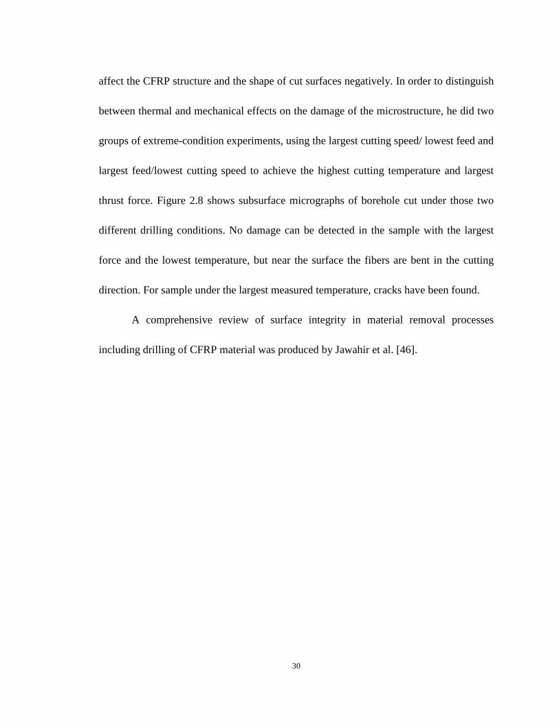
affect the CFRP structure and the shape of cut surfaces negatively. In order to distinguish
between thermal and mechanical effects on the damage of the microstructure, he did two
groups of extreme-condition experiments, using the largest cutting speed/ lowest feed and
largest feed/lowest cutting speed to achieve the highest cutting temperature and largest
thrust force. Figure 2.8 shows subsurface micrographs of borehole cut under those two
different drilling conditions. No damage can be detected in the sample with the largest
force and the lowest temperature, but near the surface the fibers are bent in the cutting
direction. For sample under the largest measured temperature, cracks have been found.
A comprehensive review of surface integrity in material removal processes
including drilling of CFRP material was produced by Jawahir et al. [46].

31
Figure 2.14: Diameter variation as a result of tool heating [6].
Figure 2.15: Micrographs of CFRP borehole surface layers for two process conditions
generated by conventional drilling [4].
2.8 Analytical Models
Delaminaton during drilling in composite laminates can be an outcome of two
types of damage mechanisms that are different in their causes and effects: peel-up
delamination and push-down delamination [8]. The latter delamination type is more

32
important since exit side delamination often is more severe than entry side delamination.
Due to the complication of damage mechanisms, exit delamination can be influence by
many factors (cutting tool geometry, cutting parameter, cutting temperature, etc.).
Analysis of delamination mechanisms during drilling using a linear elastic
fracture mechanics (LEFM) approach has been developed and different models are
presented. Among these, the one most referred to is the Hocheng-Dharan delamination
model [9]. They introduced the idea of critical thrust force, which can be estimated using
the equation they provided. Critical thrust force is the minimum force above which
delamination is initiated .The applied thrust force should not exceed this value, which is a
function of the material properties and the uncut thickness to avoid delamination [47]. As
shown in Figure 2.9, the cylinder in the middle represents the drill with diameter D, 𝐹𝐴
is the applied thrust force, X is the displacement, H is the thickness of the structure, h is
the uncut depth under tool, and a is the assumed size of an existing crack. As the drill
cuts downwards, the uncut laminates under the tool are pushed and deformed elastically
by the thrust force. If the resulting strain at the tip of the existing crack goes beyond the
critical value, crack propagation occurs. In 1997, Tsao and Chen [47] gave the details of
derivation of the equation of critical thrust force. Equation of energy balance, from linear
elastic fracture mechanics, can be written as:
𝐺𝑑𝐴 = 𝐹𝐴 𝑋 - dU (2.1)
𝐺 is the crack propagation energy and U is the stored strain energy. To find the

33
correlations between 𝐹𝐴, 𝑋, and 𝑈, classic plate bending theory for a circular plate with
clamped ends and concentrated load is used in this model [48].
The critical thrust force at the onset of crack propagation can be calculated as:
𝐹𝐴𝑐𝑟 = 𝜋[ 8𝐺𝐸ℎ3
3(1−𝑣2)]1/2 (2.2)
where, 𝑣 is Poisson’s ratio, 𝐸 is Young’s modulus, and 𝐺𝐼𝐶 is the critical crack
propagation energy in mode I. The value of 𝐺𝐼𝐶 is assumed as constant because 𝐺𝐼𝐶
was proven by Saghizadeh and Dharan [49] to be only a mild function of strain-rate. In
Equation (2.2), G is replaced by 𝐺𝐼𝐶 since value is easily measured.
Figure 2.16: Circular plate model for delamination analysis [47].
Later work of Won [50] presented a derivation of drilling force relationships.
Following the work of Shaw and Oxford [51], the thrust force and cutting force during
drilling may be described by the empirical relations.
Assuming that u, which is the specific cutting energy for a drilling operation, remains
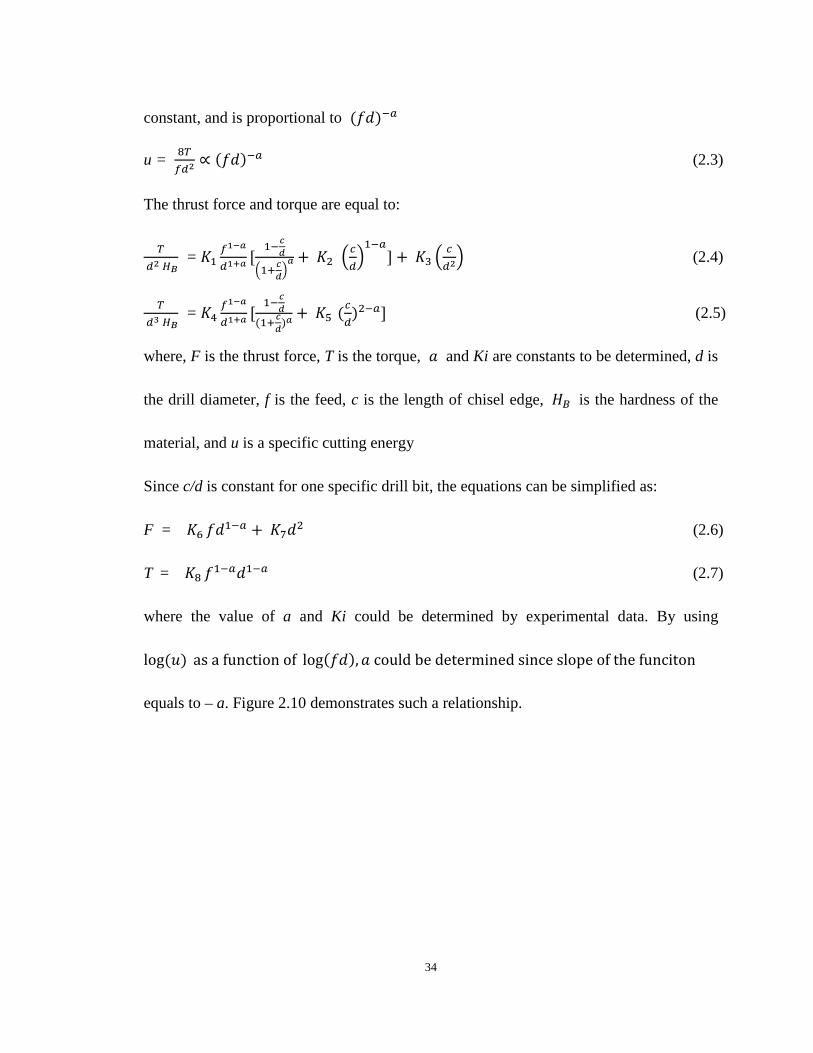
34
constant, and is proportional to (𝑓𝑑)−𝑎
u = 8𝑇𝑓𝑑2
∝ (𝑓𝑑)−𝑎 (2.3)
The thrust force and torque are equal to:
𝑇 𝑑2 𝐻𝐵
= 𝐾1𝑓1−𝑎
𝑑1+𝑎[
1−𝑐𝑑�1+𝑐𝑑�
𝑎 + 𝐾2 �𝑐𝑑�1−𝑎
] + 𝐾3 �𝑐𝑑2� (2.4)
𝑇 𝑑3 𝐻𝐵
= 𝐾4𝑓1−𝑎
𝑑1+𝑎[1−𝑐𝑑
(1+𝑐𝑑)𝑎+ 𝐾5 (
𝑐𝑑
)2−𝑎] (2.5)
where, F is the thrust force, T is the torque, 𝑎 and Ki are constants to be determined, d is
the drill diameter, f is the feed, c is the length of chisel edge, 𝐻𝐵 is the hardness of the
material, and u is a specific cutting energy
Since c/d is constant for one specific drill bit, the equations can be simplified as:
F = 𝐾6 𝑓𝑑1−𝑎 + 𝐾7𝑑2 (2.6)
T = 𝐾8 𝑓1−𝑎𝑑1−𝑎 (2.7)
where the value of a and Ki could be determined by experimental data. By using
log(𝑢) as a function of log(𝑓𝑑),𝑎 could be determined since slope of the funciton
equals to – a. Figure 2.10 demonstrates such a relationship.

35
Figure 2.17: Plot of the function [49].
To control a drilling machine with force feedback, one should try establishing
relationships between the drilling forces and cutting parameters such as feed, drill
diameter, and material properties. These relationships with the predicted critical thrust
force for a specific material type can be incorporated into the CNC program for
damage-free drilling in a time-optimal manner. In this case, an attempt was made to
derive such equations based on the experimental results
Finding the critical value by using Equation (2.2), the researcher then found the
feed by using Equation (2.7) under this value. It is notable that equations for critical value
of thrust force can be various due to the different geometry of drill bit. The point here is
to determine the critical value and then find the proper feed rate. Fernandes and Cook
reported such an approach [47]. The novelty of their work is that they also consider the
tool-wear as a factor in their analytical model. The results of their model are closer to the
experimental data compared with the previous model made by other researchers. The

36
modified equation is shown below:
𝐹(𝑓,𝑑,𝑤𝑒𝑎𝑟) = Tool-wear coefficient * (𝐾1 𝑓𝑑1−𝑎 + 𝐾2𝑑2) (2.8)
Gururaja and Ramulu [48] reviewed several previous analytical models, and
proposed a modified exit-ply delamination model. A comparison of the existing models
with experimental data indicates that the proposed modified exit-ply delamination model
yields better correlation. The modified equation is shown as follows, and would be
explained further in latter chapters:
(𝑃𝑐)𝑚𝑜𝑑𝑖𝑓𝑖𝑒𝑑 = � 𝜋𝐺𝐼𝑐𝜉((𝐶3/3)−𝐾)
(2.9)
2.9 Critical Analysis
As discussed in the previous sections, significant work has been done in drilling
of CFRP materials. Table 2.1 summarizes the major findings of drilling CFRP, and in
order to better serve this research,it also includes research areas that have not been done
in the previous studies. Generally speaking, although many aspects of drilling CFRP
material have been studied, none of them has considered the effect of cryogenic cooling
on the drilling process. Therefore, it is necessary to study and find how would the cooling
effect of liquid nitrogen impact the cutting performance in drilling of CFRP material in
terms of parameters such as thrust force and torque, delamination, hole quality, surface
integrity, etc.

37
2.10 Summary
As shown above, most problems related to drilling CFRP are caused by the high
thrust force during the drilling and induce damages such as delamination. Also, due to the
low thermal conductivity of CFRP material, cutting temperature in the drilling of CFRP
laminates is usually extremely high compared with cutting temperature in metal cutting.
This would lead to a degradation of matrix material, increase in tool-wear rate, and thus
cause elevation of surface roughness, subsurface damage, diameter error increase, etc.
Table 2.1: General evaluation of drilling of CFRP materials
Reference Major findings and brief explanation Work not done
Franke, 2011; Faraz et al., 2009
Thrust force and torque increase with the increase of cutting edge radius.
Delamination increases with the increase of cutting edge radius.
Influence of cutting parameter and cooling
conditions on cutting edge radius has not been studied.
Weinert and Kempmann, 2004; Brinksmeier et al., 2011
Large cutting temperatures and forces can affect the CFRP structure and shape of cut surfaces negatively.
Subsurface damage was observed.
All test were dry drilling, no coolant was used during
the drilling process.
Shyha et al., 2011
Effect of cutting parameter on diameter error, roundness.
All tests were dry cutting.
Shyha et al., 2011; Park et al., 2011
Effect of cooling conditions on tool-wear performance and thrust
force and torque results.
Lack of experiments under cryogenic cooling.
Hocheng and, Tsao, 2003; 2006
Linear elastic fracture mechanics (LEFM) approach has been developed
to predict critical thrust force.
All tests were dry cutting, no cutting fluid or other
coolant was applied during the cutting process.

38
The key to success of drilling CFRP materials is to keep the sharpness of the drill
bit, maintain a low level of thrust force, and achieve a low cutting temperature. Applying
coolant would to some degree reduce the cutting temperature, and thus reduce the defects
related to thermal damage, as well as lower the tool-wear rate. But, since materials tend
to have higher modulus under coolant, thrust and torque might elevate.
Meanwhile, to the best of our knowledge, no single study regarding drilling CFRP
material under cryogenic cooling has been conducted yet. The purpose of this project is
to investigate influence of cryogenic cooling in drilling of CFRP laminates. The
assumption is that not only can borehole quality and borehole surface integrity be
enhanced by applying cryogenic cooling during the drilling process, but tool-wear
resistance of the drill bit also could benefit from lower cutting temperatures. Different
aspects of the drilling performance, such as the force result, the borehole quality,
borehole surface integrity and the tool-wear, have been studied under different cutting
parameters and cooling conditions.

39
CHAPTER 3: EXPERIMENTAL SETUP AND PROCEDURE
In this chapter, the details of experimental setup and procedure to carry out the
investigations are discussed, including the setup of drilling used to conduct the
experiments, and the configuration of PC-based data acquisition system to measure the
cutting force and torque. The cooling techniques and equipment applied to carry out the
experiments are introduced, and the instruments and methods used to measure roundness,
diameter deviation, and surface roughness are also discussed in this chapter. Finally, the
method of evaluating delamination, and the method of observing subsurface damage, as
well as the method of studying burr generation of drilled hole using optical technique, are
also presented. A schematic diagram shown in Figure 3.1 summarizes the measurements
taken as well as instruments used in this study.
Figure 3.1: Schematic diagram of measurements and instruments selection.
40
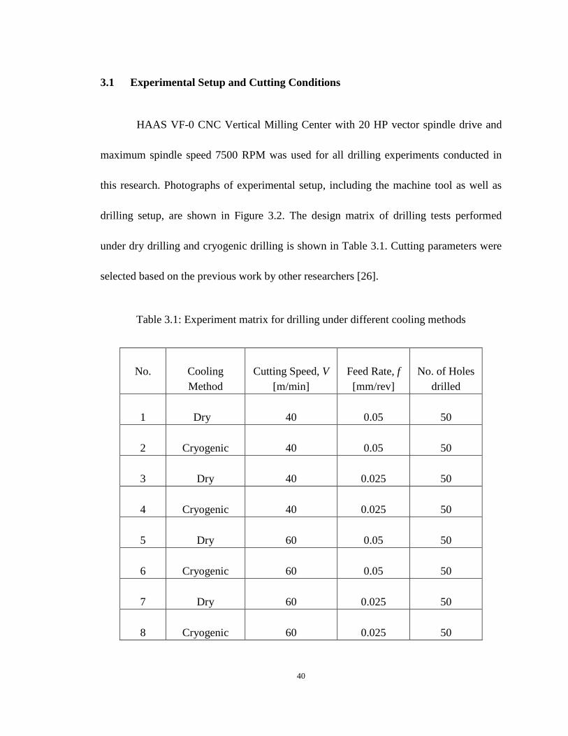
3.1 Experimental Setup and Cutting Conditions
HAAS VF-0 CNC Vertical Milling Center with 20 HP vector spindle drive and
maximum spindle speed 7500 RPM was used for all drilling experiments conducted in
this research. Photographs of experimental setup, including the machine tool as well as
drilling setup, are shown in Figure 3.2. The design matrix of drilling tests performed
under dry drilling and cryogenic drilling is shown in Table 3.1. Cutting parameters were
selected based on the previous work by other researchers [26].
Table 3.1: Experiment matrix for drilling under different cooling methods
No.
Cooling Method
Cutting Speed, V
[m/min]
Feed Rate, f
[mm/rev]
No. of Holes
drilled 1
Dry
40
0.05
50
2
Cryogenic
40
0.05
50
3
Dry
40
0.025
50
4
Cryogenic
40
0.025
50
5
Dry
60
0.05
50
6
Cryogenic
60
0.05
50
7
Dry
60
0.025
50
8
Cryogenic
60
0.025
50

41
Figure 3.2: (a) Experimental setup of the drilling device; (b) HAAS VF-0 CNC vertical
milling center.
(a)
(b)

42
3.2 Cutting Tool and Workpiece Materials
Sandvik CoroDrill 860 drill bit was used in this study. A fresh drill was used for
each test run. This uncoated carbide drill is a conventional twist drill with two flutes and
a diameter of 9.92 mm. The point angle of this drill is 130o. It also features a two coolant
supply hole to allow coolant to come through. Figure 3.3 shows the pictorial view of the
drill bit used in the experiment.
Figure 3.3: Sandvik CoroDrill 860 drill bit.
The carbon fiber reinforced plastics material used in this research was a balanced
quasi-isotropic layup utilizing in a 2x2 twill pattern woven CFRP laminates material. The
lay-up of the woven laminates were oriented as standard 0o/ +45o/ 90o /
−45o directions. The fibre volume fraction of the CFRP material is about 0.6. For
technical reasons, in order to supply the cryogenic cooling internally through the coolant
hole, it was necessary to perform the drilling test with an upside down setup with rotating
composite specimen and a fixed drill bit. The so-called inverted drilling setup is shown in
Figure 3.2. The dimensions of carbon fiber reinforcement plastics block specimen were
approximately 20 mm x 20 mm x 18 mm (shown in Figure 3.4), and it was placed in a
specially designed workpiece holder during the drilling process. The workpiece rotated
while drill bit in the bottom of the milling center was kept steady during the drilling

43
process. The dynamometer was placed on the bed of the machine in order to record thrust
force and torque. On top of the dynamometer was a specially designed tool holder.
Figure 3.4: Workpiece material.
3.3 Dynamometer and Data Acquisition System
Kistler Type 9272 4-component dynamometer, 1679a5 high insulation connecting
cable and two Type 5011A charge amplifiers were used in the experiment. The thrust
force and torque generated are recorded during drilling of CFRP materials under various
combinations of cutting parameters and cooling conditions by the dynamometer which
was connected to a NI USB-6366 X series data acquisition system paired with Lab View
Signal Express 2011 software. The thrust force and torque data obtained were transferred
into an Excel spread sheet.
Pictorial view and dimensions of dynamometer are shown in Figure 3.5. The
calibration of dynamometer was done before performing the drilling test. A specially

44
designed tool holder was built on top of the dynamometer for the experimental setup to
keep the drill steady during the drilling process. The thrust force was calibrated by
applying different load by putting certain weight block on the dynamometer. For the
calibration of torque, a torque wrench was used to apply different torques. The
dynamometer was calibrated under ambient conditions. Humidity and temperature
recorded at the time of calibration were 45% and 24.3℃ respectively.
NI USB-6366 X series is a PC-based data acquisition system. The software used
in this research is Lab View Signal Express 2011, which is very user-friendly, and allows
users to easily process the acquired data after recording. Pictorial view of data acquisition
system with Kistler 5011A charge amplifiers is shown in Figure 3.6. NI USB-6366 was
put in the sliver box and was connected to a laptop. Blue boxes in the bottom right corner
are charge amplifiers and each of them was recording one channel of signal. Two of them
were used in the experiment since in this research only the thrust force and the torque
were recorded.

45
Figure 3.5: (a) Dimensions of dynamometer Type 9772; (b) pictorial view of dynamometer; (c) specially designed tool holder.
(a)
(b) (c)
(a)

46
Figure 3.6: Data acquisition system and charge amplifiers.
3.4 Cooling Technique for Cryogenic Drilling of the CFRP Laminates
Liquid nitrogen was used as coolant in this research in order to reach the
cryogenic temperature during the drilling. Internal pressure building tank of 250 liters
capacity filled with liquefied nitrogen gas was chosen to supply the cooling liquid
nitrogen and to keep the cryogenic supply constant for every drilling test. Valves were
built on the liquid nitrogen tank, and also on the hose connecting the cylinder and the tool
holder mentioned early. Both valves were opened up to the maximum turn to allow the
liquid nitrogen go through the tool holder and the coolant supply holes and thus apply
cryogenic cooling internally during drilling. Liquid nitrogen tank with hose is shown in
Figure 3.7.

47
Figure 3.7: Liquid nitrogen tank and hose.
3.5 Borehole Surface Integrity Inspection and Borehole Quality Assessment
The drilling process is usually the final process of a production cycle. To avoid
rejection because of the poor tolerance, the surface finish of borehole has to be
considered as the priority of drilling CFRP material.
In order to evaluate the hole quality and surface integrity with various cutting
parameters and under different cooling conditions, several instruments were used and
many hole quality and surface integrity criteria were studied in this study. These criteria
include: delamination, burr generation, surface roughness, diameter deviation of the
borehole, and roundness.
48
Since no significant delamination and burr generation were found on the entry
side of the borehole in any cutting parameters or cooling conditions, this study only
focuses on exit delamination and exit burr generation. Following Khashaba’s [12]
methods, machined samples were first scanned by Epson 3230 scanner, which has a
maximum 1600 DPI. The drilled specimens are to be placed directly on the glass plate of
the scanner in such a manner that damaged areas and borehole could be recorded. This
technique is calibrated by measuring several dimensions on a standard steel ruler. Then
the pictures obtained were evaluated by image software CorelDraw (free trial full
function version). The software has multiple functions, which could measure the diameter
of the damaged area and the diameter of the borehole. By calculating the delamination
factors, the hole quality from delamination point of view can be evaluated. Similar to
delamination evaluation, several comparisons were made between boreholes obtained
with different cutting parameters and under different cooling conditions by visually
inspecting images recorded by the scanner.
Diameter error and roundness were measured by TESA Micro-Hite 3D measuring
system. This coordinate measuring machine uses a probe (5 mm diameter) to measure the
points on a part (in this study, the points are on the internal surface of the borehole). Each
point on the internal surface is unique to the machine’s coordinate system. The picture of
measuring diameter error and roundness is shown in Figure 3.8. Machined sample was
put on top of a pair of parallel set in order to keep the height constant, and it was also

49
clamped in a vise to be kept steady during the measuring process. Points were taken at
different depths for one sample and were taken multiple times in different areas in the
same depth. Then, the CMM combines the measured points to evaluate the diameter error
and the roundness.
Surface roughness measurement was done by using Zygo NewView™ 7300 white
light interferometer (shown in Figure 3.9) combined with Windows-based software
Metro Pro to achieve the characterizing and qualifying of surface roughness, critical
dimensions, and other topographical features including the cutting edge radius of drill bit.
Subsurface quality was investigated by analyzing micrographs in cross-sectional areas
using Nikon EPIPHOT 300 inverted Metallurgical Microscope shown with objective
lenses ranging from 2.5X to 50X.
Cutting edge radius progression and outer corner wear were also measured using
Zygo profilometer and Microscopes, respectively, and these results will be discussed in
the next chapter.

50
Figure 3.8: TESA Micro-Hite 3D CMM.
Figure 3.9: Zygo NewView™ 7300 White Light Interferometer.

51
CHAPTER 4: RESULTS AND DISCUSSION ON TOOL-WEAR, THRUST FORCE AND TORQUE
The purpose of the present research work is to study the drilling performance in
cryogenic drilling of CFRP materials, using uncoated carbide drill bits. The machinability
evaluation variables are thrust force, torque, delamination factor, subsurface damage,
surface roughness, diameter error, roundness, cutting edge radius, and outer corner wear.
This chapter presents the results of an experimental investigation of the effects of
machining conditions on the force data from drilling of CFRP materials. The force results
investigated in this chapter include thrust force and torque. In addition, the effects of
cryogenic cooling on outer corner wear were also studied. The influence of cryogenic
cooling on cutting edge radius of the tools is one of the most important topics
investigated in this chapter, since the cutting edge radius has been shown to significantly
influence force results, and also to have a strong influence on surface integrity of the
machined CFRP material. A correlation between the thrust force and the cutting edge
radius has also been established. Finally, experimental results discussed in the early part
of this chapter serve as a basis for the development of an analytical model for drilling
CFRP composites, which is presented at the end of this chapter.
The results show that cryogenic drilling leads to significant improvement of wear
performance in drilling CFRP materials in terms of: (a) lower cutting edge wear rate, and

52
(b) reduced outer corner wear. These changes should notably enhance the quality and
surface integrity of machined CFRP borehole. Delamination, surface roughness and all
other surface integrity and hole quality parameters of these machined samples will be
presented and discussed in Chapter 4. It is also notable that thrust force and torque are
much larger in cryogenic drilling than under dry condition.
4.1 Effects of Cryogenic Cooling on Tool-wear
The influence of cutting edge radius on borehole quality in drilling CFRP
materials, especially delamination and burr generation, has been reported in the literature
by many researchers. A smaller cutting edge was found to: (a) induce lower thrust force,
and (b) contribute to cutting the carbon fiber effectively instead of pushing or tearing.
Meanwhile, the effect of outer corner wear on burr generation is also frequently reported
in the literature. The application of liquid nitrogen during machining metallic materials
was found to improve the tool-wear performance. Therefore, the focus of this section is to
investigate the influences of cryogenic cooling on tool-wear performance in drilling
CFRP materials.
4.1.1 Cutting edge radius
The cutting edge radius for fresh drill bit is about 18 μm. The actual values were
measured by Zygo New View 5300 measurement system before machining to make sure

53
the edge used was within the range. Figure 4.1 schematically describes the cutting edge
rounding. Cutting edge radius value in this study is an average of 10 values recorded
along the main cutting edge of the drill bit to ensure the accuracy. Measuring points were
selected discretely as shown in Figure 4.2. Typical oblique plots measured by Zygo for
some cutting edge radius results are also shown in Figure 4.3. The 3D plots of the cutting
edge of drill bits after 50 drillings at f = 0.025 mm/rev and V = 40 m/min under dry and
cryogenic cooling methods provide a direct comparison of the differences in edge radius.

54
Figure 4.1: Cutting edge rounding: (a) Sharp cutting edge (b) Blunt smoothly worn, rounded cutting edge [8].
Figure 4.2: Measuring cutting edge radius using Zygo New View 5300 White Light Interferometer.

55
(a)
(b) Figure 4.3: Typical oblique plots of edge radius measurement of drill bits at f = 0.025 mm/rev and V = 40 m/min after 50 drillings: (a) under cryogenic cooling method, cutting edge radius
= 26.1 μm; (b) under dry cooling method, cutting edge radius = 39.4 μm.
56
During the drilling experiments, cutting edge radius was measured after every 10
drill holes on each drill bit, and the results of cutting edge radius progression for all tools
and cutting parameters are plotted in Figure 4.4 and Figure 4.5. The application of liquid
nitrogen cooling led to about 40% decrease in cutting edge wear for both 0.025 and 0.05
mm/rev feed rate. The reason for this reduction in cutting edge radius observed may be
due to the significant reduction in the cutting temperature by cryogenic cooling. The low
temperature helped reduce abrasion wear (which is the more dominant wear mode in
machining CFRP materials) by retaining the tool hardness, and also adhesion and
diffusion types of wear that are highly sensitive to temperature [59].
The cutting edge radius slightly increased with the increasing feed rate, which
may be due to the fact that small values for feed rate were chosen in this study to avoid
severe delamination, and thus the margin of parameter selection is not very large (0.025
mm/rev). It is noted that the progression in cutting edge wear is not uniform: At the start
of drilling, the new cutting edges of fresh drills, having smaller cutting edge radius,
induce cutting forces to relatively small area of contact. Consequently, the extremely high
contact pressure resulting in the tool–workpiece system behaving as a heavily loaded
system giving rise to a high wear rate. After the initial wear or cutting edge rounding, the
increase in contact area between the tool and the workpiece causes lower contact stresses.
As the tool–workpiece system becomes a lightly loaded system, the wear rate is reduced

57
and becomes nearly constant with the increase in the drilling time (or distance) [57, 58].
It is also noticed that the cutting edge radius rises with increasing cutting speed.
After drilling 50 holes, the cutting edge radius increased 4.5% and 1%, under dry and
cryogenic drilling conditions respectively, when the cutting speed was increased from 40
m/min to 60 m/min at the feed rate of 0.05 mm/rev. The increase is due to the fact that
higher cutting speed generates more heat, and thus leading to increased wear rate in the
drill bit.
Generally speaking, from the basic findings of some of the researchers, it can be
confirmed that the wear is largely smooth and uniform [8]. In this study, it is observed
that the cutting edge wear in drilling of CFRP materials is uniform under both dry and
cryogenic cooling conditions, but it is notable that there was more deviation in the results
of cutting edge wear in dry drilling than in cryogenic drilling.

58
(a)
(b) Figure 4.4: Cutting edge rounding progression at: (a) f = 0.025 mm/rev and V = 40 m/min;
(b) f = 0.05 mm/rev and V = 40 m/min.
18
23
28
33
38
43
48
0 10 20 30 40 50
Cut
ting
Edge
Rad
ius
(μm
)
Hole Number
CryogenicDry
18
26
34
42
50
0 10 20 30 40 50
Cut
ting
Edge
Rad
ius
(μm
)
Hole number
Cryogenic
Dry

59
(a)
(b) Figure 4.5: Cutting edge rounding progression at: (a) f = 0.025 mm/rev and V = 60 m/min;
(b) f = 0.05 mm/rev and V = 60 m/min.
18
23
28
33
38
43
48
0 10 20 30 40 50
Cut
ting
Edge
Rad
ius
(μm
)
Hole Number
CryogenicDry
18
23
28
33
38
43
48
53
0 10 20 30 40 50
Cut
ting
Edge
Rad
ius
(μm
)
Hole Number
CryogenicDry

60
4.1.2 Outer corner wear
In order to study the effect of cryogenic cooling on outer corner wear
performance of uncoated drills, the result of outer corner flank wear was examined using
microscopes. By definition, outer corner wear is the wear land on the corner of the flank
face of the drill bit. Method of measuring outer corner wear is shown in Figure 4.6.
Measuring outer corner wear should take the following steps:
Choose a fixed reference point
Before the drilling process, measure the width of margin
After drilling, measure the distance between the reference points and the wear land.
The value of outer corner wear should be the value of margin width minus the
distance between reference points and wear land.
During the experiments, the outer corner wear was measured on an optical
microscope after every 10 drill holes. Before the drilling test, the image of the fresh drill
was taken and is shown in Figure 4.7. Typical images captured by microscopes for outer
corner wear of drill bit under dry and cryogenic coolings are shown in Figure 4.8. As
shown, cryogenic drilling significantly improves the wear performance in drilling CFRP
materials in terms of having lower outer corner wear compared with dry drilling. It shows
that outer corner wear rates are 114.7 μm and 219.8 μm after 20 drill holes, and 196.1 μm
and 449.1 μm after 50 drill holes under cryogenic and dry conditions, respectively at f =

61
0.05 mm/rev and V = 60 m/min. The progression of outer corner flank wear from drill
tests carried out on an uncoated twist drill under dry and cryogenic cooling conditions is
shown in Figures 4.9 and 4.10. The results share the same pattern as the result of cutting
edge radius: the outer corner wear rate is higher at the beginning stage and becomes
lower after about 10 to 20 drill holes because the tool-workpiece system is more loaded
when the drill is fresh. The influence of cryogenic cooling on outer corner wear rate was
significant. There were 145% and 165% increases, respectively in outer corner wear at
different feed rates when the cooling condition switches from cryogenic to dry. The
reason for improvement of the outer corner wear rate under cryogenic condition may also
be attributed to the greater hardness of the drill bit at a lower temperature. According to
previous studies by many other researchers, the drills were deemed to have failed when
the wear land reached 66% of the total margin width [19], and none of the tests in this
study exceeded this value.

62
Figure 4.6: Method of measuring outer corner wear [30].
Figure 4.7: Cutting edge rounding progression at f = 0.05 mm/rev and V = 60 m/min.

63
Figure 4.8: Cutting edge rounding progression at f = 0.05 mm/rev and V = 60 m/min.

64
Figure 4.9: Outer corner wear progression at f = 0.025 mm/rev and V = 60 m/min.
Figure 4.10: Outer corner wear progression at f = 0.05 mm/rev and V = 60 m/min.
4.2 Effects of Cryogenic Cooling on Thrust Force and Torque
This section of the chapter presents results pertaining to the effects of cryogenic
cooling of CFRP materials on drilling thrust force and torque. The thrust force and torque
0
50
100
150
200
250
300
350
400
450
0 10 20 30 40 50
Out
er c
orne
r wea
r (μm
)
Hole Number
CryogenicDry
050
100150200250300350400450500
0 10 20 30 40 50
Out
er c
orne
r wea
r (μm
)
Hole Number
CryogenicDry

65
components measured by the dynamometer are shown in Figures 4.11 and 4.14. As one
of the most important hole quality criteria in drilling CFRP materials, delamination is
proved to be related to maximum thrust force by many researchers. In this study, all the
force data are maximum thrust force and torque.
4.2.1 Thrust force
The application of liquid nitrogen had a large influence on the thrust force. As
shown in Figure 4.11, compared with data obtained under dry machining, the average
maximum thrust force for cryogenic drilling was increased by 91%, 69%, 112% and 77%
respectively. The increase is due to the effective cooling from the liquid nitrogen applied
via drill bit coolant holes, which enhances the mechanical properties of the materials. The
cryogenic temperature characteristic of several carbon fiber reinforced composite
materials was investigated and summarized in detail in relation to its mechanical and
thermal aspects by Reed and Golda [54, 55], who reported that Young’s modulus and
tensile strength of carbon fiber reinforced composites increase as the temperature
decreases. Kim and Donaldson [56] also studied mechanical properties of carbon fiber
reinforced epoxy polymer composite. They claimed that thermo-mechanical properties,
such as transverse modulus, shear modulus, transverse shear modulus and transvers
strength were increased when the temperature was reduced.
Another reason for elevation of thrust force in cryogenic drilling may be because

66
of the experimental setup in this study. Liquid nitrogen was delivered internally via drill
bit coolant hole. After cooling the tool and workpiece, the liquid nitrogen converts to gas,
but with no outlet. Therefore there was a lot of pressure built up inside the specimen and
push the specimen to the dynamometer, which may increase the result of thrust force.
The influence of feed rate on thrust forces, both under dry and cryogenic
conditions, was significant. There were 60% and 53% increases respectively in the thrust
force under dry and cryogenic conditions, when the feed rate was increased from 0.025
mm/rev to 0.05 mm/rev at the cutting speed of 40 m/min. When the cutting speed was
increased to 60 m/min, there were 64% and 46% increases, respectively in the thrust
force under dry and cryogenic conditions when the feed rate was increased from 0.025
mm/rev to 0.05 mm/rev.
In metal cutting, increasing cutting speed usually affects the forces in two ways:
(a) generating more heat leading to a higher temperature and reducing the forces; and (b)
increased strain-rate leading to stronger work hardening and thus increasing the forces. In
the drilling of CFRP materials, the only cutting mechanism is fracture, there were no
plastic deformations involved during the drilling process, and thus increasing cutting
speed does not lead to work hardening effect on CFRP materials. As it is seen in Figure
4.11, thrust force only slightly decreased with the increase of cutting speed under both
dry and cryogenic cooling. This may be due to the fact that the thrust force is less
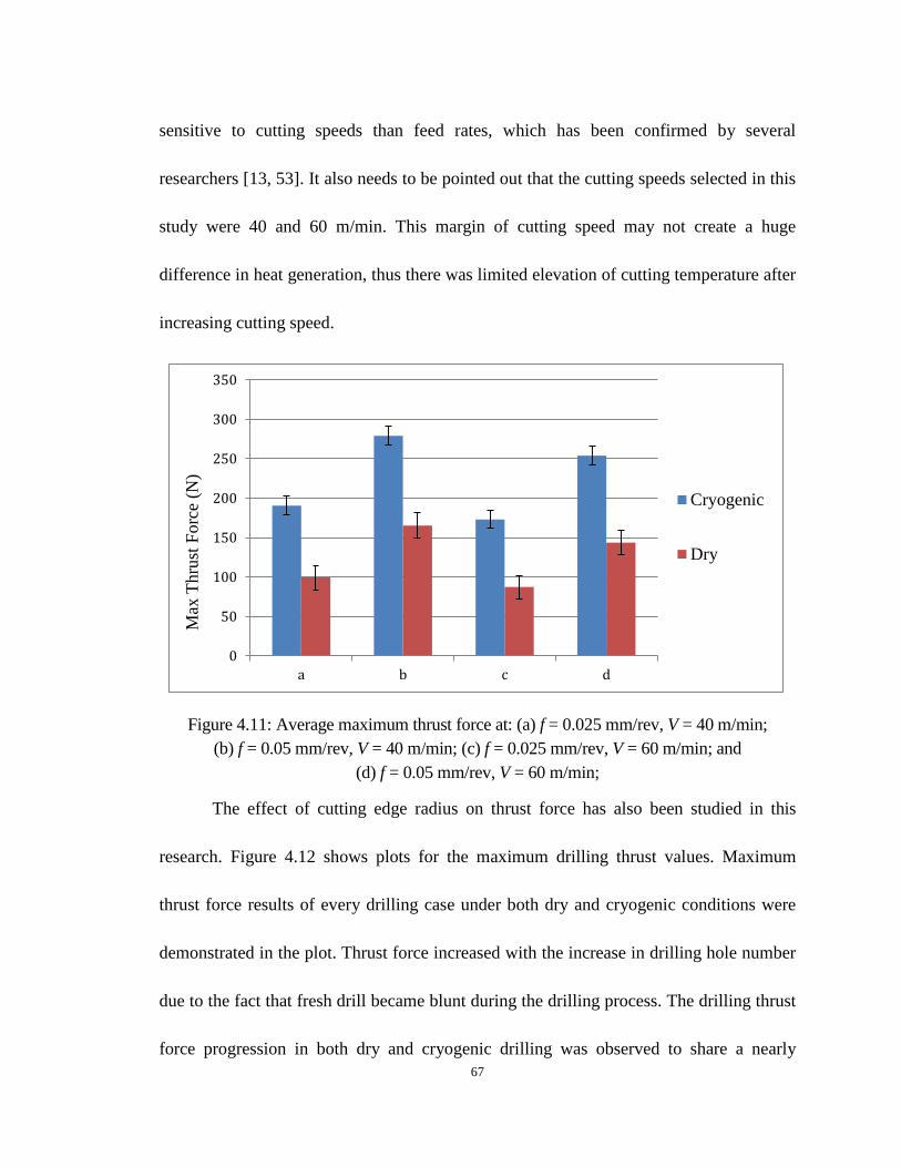
67
sensitive to cutting speeds than feed rates, which has been confirmed by several
researchers [13, 53]. It also needs to be pointed out that the cutting speeds selected in this
study were 40 and 60 m/min. This margin of cutting speed may not create a huge
difference in heat generation, thus there was limited elevation of cutting temperature after
increasing cutting speed.
Figure 4.11: Average maximum thrust force at: (a) f = 0.025 mm/rev, V = 40 m/min; (b) f = 0.05 mm/rev, V = 40 m/min; (c) f = 0.025 mm/rev, V = 60 m/min; and
(d) f = 0.05 mm/rev, V = 60 m/min;
The effect of cutting edge radius on thrust force has also been studied in this
research. Figure 4.12 shows plots for the maximum drilling thrust values. Maximum
thrust force results of every drilling case under both dry and cryogenic conditions were
demonstrated in the plot. Thrust force increased with the increase in drilling hole number
due to the fact that fresh drill became blunt during the drilling process. The drilling thrust
force progression in both dry and cryogenic drilling was observed to share a nearly
0
50
100
150
200
250
300
350
a b c d
Max
Thr
ust F
orce
(N)
Cryogenic
Dry

68
similar trend to the progression of cutting edge radius, which indicates that thrust force
might be correlated to cutting edge radius. Figure 4.13 confirms the previous assumption,
as it shows the increasing (correlation) drilling thrust force, with the cutting edge radius
progression. Cutting edge radius values were measured after every ten drill holes and
correlated with the maximum thrust force results of corresponding drill hole number.
Thrust correlation curves for both dry and cryogenic cooling conditions, as seen from
Figure 4.13, show a relatively clear pattern that maximum thrust increases with the
increase of cutting edge radius. As discussed in the previous section, cutting edge radius
grows more slowly in cryogenic drilling than in dry drilling. In other words, according to
the correlation seen from Figure 4.13, the increasing rate of thrust force in cryogenic
drilling should be lower than in dry drilling. Figure 4.12 shows that the slope/rate of
maximum thrust progression in cryogenic drilling is slightly lower than in dry drilling.
In summary, even though results of thrust force in cryogenic drilling were higher
than in dry drilling, the increasing rate of thrust force in cryogenic drilling is lower than
in dry drilling due to the fact that cutting tool could maintain its sharpness during the
drilling under cryogenic cooling.

69
Figure 4.12: Thrust force progression at f = 0.025 mm/rev, V = 60 m/min.
Figure 4.13: Correlation between thrust force cutting and edge radius at f = 0.025 mm/rev, V = 60 m/min.
0
50
100
150
200
250
1 6 11 16 21 26 31 36 41 46
Max
Thr
ust F
orce
(N)
Hole number
Cryogenic
Dry

70
4.2.2 Torque
The mean values of maximum drilling torque results from tests with different
cutting parameters are plotted in Figure 4.14. Each data point also includes an error bar
that shows its degree of variability.
As shown in Figure 4.14, it is clear that the mean value of maximum torque
increases when the cooling condition switches from dry condition to cryogenic cooling.
This increase can be explained in a manner similar to that of drilling thrust mentioned in
the previous section: the elevation is due to the fact that the mechanical properties of the
CFRP material was enhanced at lower temperature cooling, and thus the torque was
higher under cryogenic cooling.
The effect of cutting parameters on the drilling torque can also be evaluated from
the plots in Figure 4.14. The figure shows for both cooling conditions and feed rates, the
effect of increasing speed form 40 m/min to 60 m/min is to decrease the average value of
maximum drilling torque. It also shows the influence of increasing feed rate for different
cooling conditions and cutting speeds in the increase in torque. This increase in torque
with increase in feed rate and cutting speed is due to the higher friction. As discussed in
the previous section, tool-wear increases with increase in feed rate and cutting speed, thus
blunter tools might be another reason that torque results are higher at a higher cutting
speed and feed rate.

71
The effect of cutting edge radius on torque has also been studied in this research.
Figure 4.15 shows plots for the maximum torque values under both dry and cryogenic
conditions. Torque increased with the increase in drill hole number, and in other words,
torque is also related to the sharpness of the cutting tool. Meanwhile, the trend of torque
progression in both dry and cryogenic drilling is similar to what was observed in cutting
edge progression. Figure 4.16 correlates torque to cutting edge radius. As seen from
Figure 4.16, maximum torque increases with the increasing cutting edge radius.
Figure 4.14: Average maximum torque at: (a) f = 0.025 mm/rev, V = 40 m/min; (b) f = 0.05 mm/rev, V = 40 m/min; (c) f = 0.025 mm/rev, V = 60 m/min; and
(d) f = 0.05 mm/rev, V = 60 m/min;
0
0.05
0.1
0.15
0.2
0.25
0.3
0.35
0.4
a b c d
Max
torq
ue (N
.m)
Cryogenic
Dry
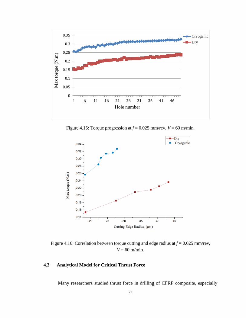
72
Figure 4.15: Torque progression at f = 0.025 mm/rev, V = 60 m/min.
Figure 4.16: Correlation between torque cutting and edge radius at f = 0.025 mm/rev, V = 60 m/min.
4.3 Analytical Model for Critical Thrust Force
Many researchers studied thrust force in drilling of CFRP composite, especially
0
0.05
0.1
0.15
0.2
0.25
0.3
0.35
1 6 11 16 21 26 31 36 41 46
Max
torq
ue (N
.m)
Hole number
CryogenicDry

73
critical the thrust force, and it was shown that this thrust force is related to hole quality
and delamination in drilling CFRP materials. Therefore, being able to accurately predict
critical thrust force could be used to optimize the cutting parameter (in this specific case
the cutting parameter is feed rate) in order to avoid defects and to improve productivity.
Hocheng-Dharan delamination model [45] has been used in this study. They
introduce the idea of critical thrust force, which can be estimated using the equation they
provided.
As shown in Figure 4.17, the cylinder in the middle represents the drill with
diameter D, 𝐹𝐴 is the applied thrust force, X is the displacement, H is the thickness of
the structure, h is the uncut depth under tool, and a is the assumed size of an existing
crack. As the drill cuts downwards, the uncut laminates under the tool are pushed and
deformed elastically by the thrust force. If the resulting strain at the tip of the existing
crack goes beyond the critical value, crack propagation occurs [45].

74
Figure 4.17: Circular plate model for delamination analysis (twist drill) [45].
In 1997, Tsao [43] gave the detail of a derivation of the equation of critical thrust
force. Equation of energy balance, from linear elastic fracture mechanics, can be written
as:
𝐺d𝐴 = 𝐹𝐴 X-dU (4.1)
where dA is the increase area of the crack, which equals to:
dA = π(𝑎 + d𝑎)(𝑎 + d𝑎) − πa2 = 2𝜋𝑎d𝑎 (4.2)
Substituting Eq. (4.2) into Eq. (4.1):
2 πGada = 𝐹𝐴dX − 𝑑𝑈 (4.3)
where G is the crack propagation energy and U is the stored strain energy.

75
To find the correlations linking 𝐹𝐴, U and X together, classic plate bending theory
for a circular plate with clamped ends and concentrated load is used in this model [44].
For a circular plate with clamped ends and a concentrated load, the stored strain energy is
[45]:
U = 8𝜋𝑀𝑋2
𝑎2 (4.4)
where M is the stiffness per unit width of the fiber reinforced materials given by
M = 𝐸ℎ3
12(1−𝑣2) (4.5)
The displacement X is expressed as:
X = 𝐹𝐴𝑎2
16𝜋𝑀 (4.6)
Substituting Eq. (4.4)-(4.6) into Eq. (4.3), the critical thrust force at the onset of crack
propagation can be calculated:
𝐹𝐴𝑐𝑟 = 𝜋[ 8𝐺𝐸ℎ3
3(1−𝑣2)]1/2 (4.7)
where 𝑣 is Poisson’s ratio, 𝐸 is Young’s modulus, and 𝐺𝐼𝐶 is the critical crack
propagation energy in mode I.
The value of 𝐺𝐼𝐶 is assumed as constant because 𝐺𝐼𝐶 was proven by Saghizadeh
and Dharan [55] to be only a mild function of strain-rate. In Eq. (4.7), G is replaced by
𝐺𝐼𝐶 since the value is easily measured.
76
The critical thrust force at the onset of crack propagation can be calculated as:
𝐹𝐴𝑐𝑟 = 𝜋[8GIC𝐸ℎ3
3(1−𝑣2)]1/2 (4.8)
Composite laminates were made of woven 2 x 2 twill woven pattern pregregs and
the lay-up of laminates was oriented as standard 0o/ +45o/ 90o /−45o directions. The
fiber volume fraction was 0.6, the thickness for a single ply is 0.42 mm, the Young’s
modulus was 17 GPa, Poisson’s ratio was 0.3, and the strain energy release rate was 90
J/m2.
Drill bits selected for this study were standard twist drill. Based on the available
information and Eq. (4.8), the critical thrust force for the CFRP composite in this study is
𝐹𝐴𝑐𝑟 = 57.2 N. Drilling tests were carried out to test the analytical model. The entire test
were performed at cutting speed of 40 m/min and feed rate range of 0.002, 0.004, 0.006,
0.008, 0.001, 0.012, 0.014, 0.016, 0.018, and 0.02 mm/rev under dry drilling.
Delamination was observed after drilling at cutting speed of 40 m/min and feed rate of
0.016 mm/rev and the maximum thrust force was record as F = 56.73 N. This result
suggested that the model is reasonable.
4.4 Summary
An experimental investigation has been conducted to study the effect of the
different machining parameters, including cooling method (dry, cryogenic), cutting speed

77
and feed rate, on the thrust force, torque and tool-wear performance in drilling of CFRP
composite. Major observations can be summarized as the following points:
Remarkable tool-wear resistance was achieved during cryogenic drilling in terms of
having lower cutting edge radius and outer corner wear compared with dry drilling.
Significant reduction of cutting temperature by supplying liquid nitrogen through
coolant hole of the drill bit onto the tool-workpiece interface is the main reason for
this superior tool-wear performance. Compared with dry drilling, cryogenic drilling
produced 53% - 63% less cutting edge radius depending on the cutting parameters:
dry drilling induced more than twice outer corner wear compared with cryogenic
drilling. Both cutting speed and feed rate were confirmed to influence cutting edge
radius and outer corner wear. Only a marginal elevation of cutting edge radius and
outer corner wear has been found with the increase of cutting speed and feed rate.
Both thrust force and torque were larger in cryogenic drilling than in dry drilling due
to the fact that cryogenic cooling increases the strength of the workpiece and makes
the material harder to drill. Using the cutting speed of 40 m/min and the feed rate of
0.05 mm/rev, the application of liquid nitrogen increased thrust force and torque by
about 70% and 61% respectively. The effect of cutting parameters on thrust force
and torque has also been investigated. Thrust force and torque increased with the
increasing feed rate, meanwhile both thrust force and torque decreased with the

78
increasing cutting speed.
An analytical model has been used to predict critical thrust force. The value is
calculated using the mechanical properties provide by the material supplier. The
applied thrust force should not exceed this value to avoid delamination. After getting
the value of critical thrust force, drilling tests were carried out in order to examine
the analytical model. All tests were performed under dry condition since no
properties of CFRP composite under cryogenic temperature were available.

79
CHAPTER 5: HOLE QUALITY AND SURFACE INTEGRITY IN DRILLING OF CFRP MATERIALS
5.1 Introduction
This chapter discusses the investigation of the effects of cooling conditions and
cutting parameters on hole quality and surface integrity of the borehole, when they are
drilled using uncoated carbide drill bit through CFRP materials. The hole quality and
surface integrity criteria investigated in this study include: delamination, burr generation,
diameter error, roundness of the borehole, surface roughness, and subsurface damage. It
has been reported that delamination and surface roughness depend on cutting edge radius;
that burr generation is related to outer corner wear; and that subsurface damage is related
to cutting temperature and thrust force. All these factors were found to be influenced by
the cryogenic cooling as seen in the previous chapters.
This study demonstrates the success of a novel setup to improve the hole quality
and surface integrity of CFRP borehole by cryogenic drilling.
5.2 Delamination
In order to evaluate the extent of the delamination damage, a term called
‘delamination factor’ was used. The delamination factor, ‘𝐹𝑑 ’, is the ratio of the
maximum diameter of the damaged zone to the diameter of the borehole [8], as shown in

80
Figure 5.1.
𝐹𝑑 = 𝐷𝑚𝑎𝑥𝐷0
(5.1)
Figure 5.1: Demonstration of 𝐷0 and 𝐷𝑚𝑎𝑥.
To calculate the delamination factor, optical images of boreholes that were drilled
through CFRP material were captured by scanner, and 𝐷0 and 𝐷𝑚𝑎𝑥 and measured by
CorelDRAW image software. Then, the delamination factor, ‘𝐹𝑑’, is calculated for each
hole using Eq. (5-1). Due to the fact that only limited delamination was observed for the
entry side in all the drilling tests, only exit delamination was calculated in this study. It
has been reported that the delamination significantly depends on the thrust force. Also, as

81
was discussed in Chapter 4, under the same cutting parameters, compared with dry
drilling, cryogenic drilling generates a much larger thrust force. Therefore, more severe
delamination occurred in drilling test under cryogenic cooling. In this study, there were 8
tests as shown in Table 3.1, and there were 50 drill holes produced for each test. Figure
5.2 shows the image of first and last boreholes under dry and cryogenic cooling
conditions at V = 60 m/min, f = 0.025 mm/rev.

82
First hole Last hole
(a) First hole Last hole
(b)
Figure 5.2: Optical images of first and last hole of CFRP materials drilled at V = 60 m/min, f = 0.025 mm/rev, under: (a) dry condition; (b) cryogenic conditions.

83
Figure 5.3 shows the average delamination of 50 drill holes at different feed rates
and cutting speeds under both dry and cryogenic cooling conditions. Machined samples
under cryogenic cooling suffered more severe delamination than the ones in dry drilling.
Generally speaking, delamination is about 11% to 15% higher in cryogenic drilling than
in dry drilling. It is also noticeable that the delamination factor increased with increasing
feed rate and decreased when the cutting speed increased from 40 m/min to 60 m/min.
These findings of delamination factor fairly agree with thrust force results in this study as
discussed in Chapter 4, which has also confirmed the previous studies by other
researchers that delamination factor highly depends on the thrust force. The highest
average delamination factor was found in the samples machined at V = 40 m/min, f =
0.05 mm/rev under cryogenic cooling.
Another noticeable fact is that there was more deviation in the delamination factor
of dry drilling due to the fact that although not as big as in cryogenic drilling, the
delamination factor increased more in dry drilling as the experiment proceeded. Figures
5.4 – 5.7 show the delamination factor progression for drilling tests at different feed rates,
cutting speeds and under different cooling conditions. The rapidly increasing rate of
delamination factor in dry drilling can be explained by the thrust force results and cutting
edge radius results presented in Chapter 4: the thrust force in dry drilling was not as big
as in cryogenic drilling, but grew faster since drill bits have better tool-wear performance

84
under cryogenic cooling; drill bits could not hold their sharpness in dry drilling as much
as in cryogenic drilling. When the drilling test proceeded under dry condition, the drill
bits pushed material rather than cut it.
Figures 5.8 and 5.9 show the correlations of the exit delamination with the
maximum thrust force and the correlations of the exit delamination with cutting edge
radius. A direct correlation is observed, which confirms that the delamination is
significantly dependent on the induced thrust force during drilling, and increases with the
increase of cutting edge radius due to the increased bluntness of the tool.
Figure 5.3: Average delamination of boreholes of CFRP materials drilled at different cutting speeds and feed rates: (a) V = 40 m/min, f = 0.025 mm/rev; (b) V = 40 m/min, f = 0.05 mm/rev;
(c) V = 60 m/min, f = 0.025 mm/rev; and (d) V = 60 m/min, f = 0.05 mm/rev.
1
1.05
1.1
1.15
1.2
1.25
1.3
1.35
1.4
1.45
(a) (b) (c) (d)
Del
amin
atio
n Fa
ctor
Cryogenic
Dry

85
Figure 5.4: Delamination progression at V = 40 m/min, f = 0.05 mm/rev.
Figure 5.5: Delamination progression at V = 40 m/min, f = 0.25 mm/rev.
1
1.05
1.1
1.15
1.2
1.25
1.3
1.35
1.4
1.45
1.5
1.55
1 6 11 16 21 26 31 36 41 46
Del
amin
atio
n Fa
ctor
Hole number
CryogenicDry
1
1.05
1.1
1.15
1.2
1.25
1.3
1.35
1.4
1.45
1.5
1 6 11 16 21 26 31 36 41 46
Del
amin
atio
n Fa
ctor
Hole number
Cryogenic
Dry
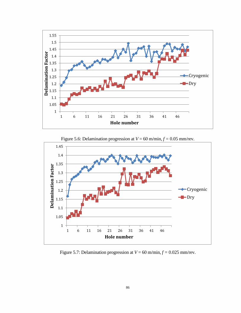
86
Figure 5.6: Delamination progression at V = 60 m/min, f = 0.05 mm/rev.
Figure 5.7: Delamination progression at V = 60 m/min, f = 0.025 mm/rev.
1
1.05
1.1
1.15
1.2
1.25
1.3
1.35
1.4
1.45
1.5
1.55
1 6 11 16 21 26 31 36 41 46
Del
amin
atio
n Fa
ctor
Hole number
CryogenicDry
1
1.05
1.1
1.15
1.2
1.25
1.3
1.35
1.4
1.45
1 6 11 16 21 26 31 36 41 46
Del
amin
atio
n Fa
ctor
Hole number
CryogenicDry
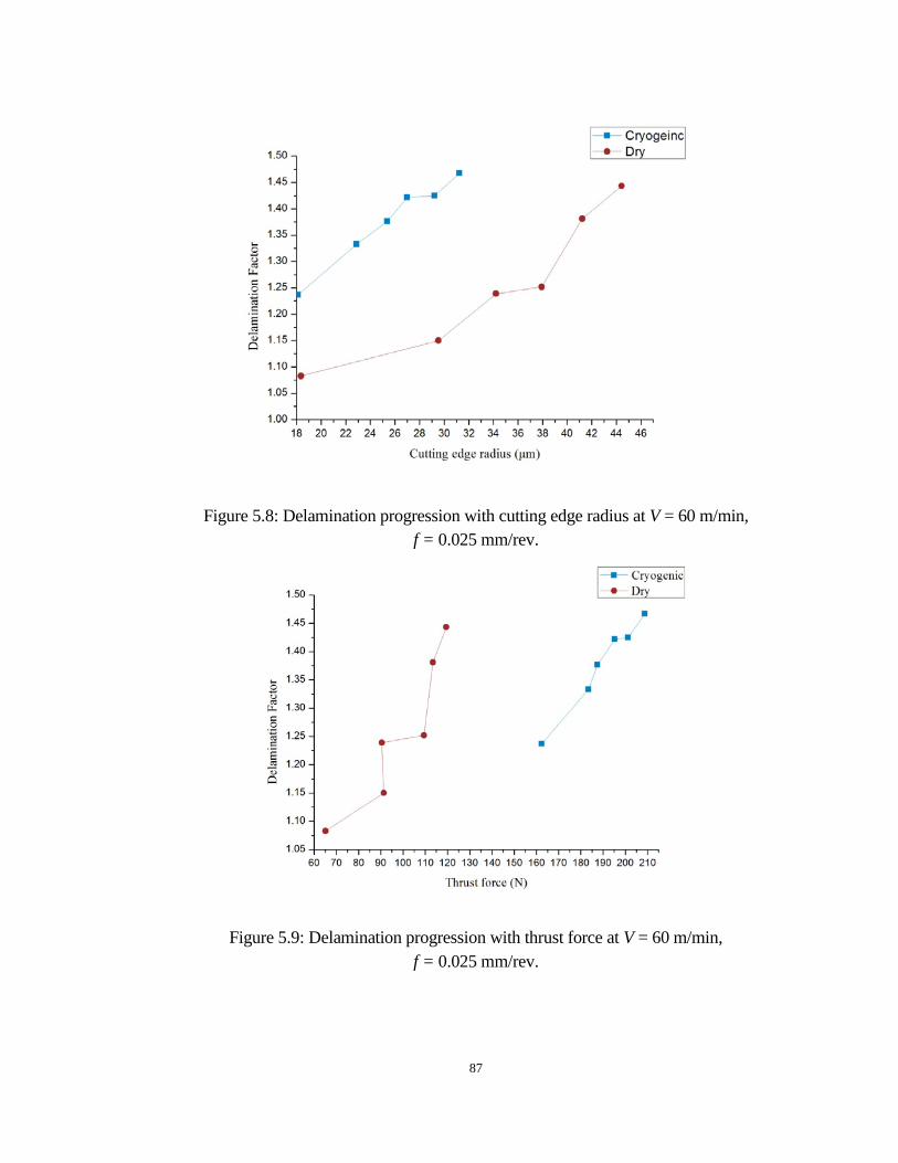
87
Figure 5.8: Delamination progression with cutting edge radius at V = 60 m/min, f = 0.025 mm/rev.
Figure 5.9: Delamination progression with thrust force at V = 60 m/min, f = 0.025 mm/rev.

88
As discussed in Chapter 2, it has been reported that a back-up support would
significantly minimize delamination in drilling of CFRP materials. As shown in Figure
5.10, CFRP cubic was sliced into a 2 mm plate as the back-up material and was adhered
to the exit side of workpiece. The adhesion material was only applied to the corners of
the exit side surface (avoiding the drilling area) in order to make sure that drilling process
would not be influenced by the adhesion. The experimental matrix of this extended work
is shown in Table 5.1. Both dry and cryogenic cooling methods were used for the purpose
of comparison. Each test performed five drillings and a comparison of last borehole with
or without back-up support at different cutting parameters and the associated cooling
methods are listed in Figure 5.6.
Figure 5.10: Back-up materials and preparation of samples with back-up materials.

89
Table 5.1: Experiment matrix for drilling under different cooling methods
No.
Cooling Method
Cutting Speed, V
[m/min]
Feed Rate, f
[mm/rev]
No. of Holes
drilled
With or Without Back-up
1
Dry
60
0.05
5
With
2
Cryogenic
60
0.05
5
With
3
Dry
60
0.05
5
Without
4
Cryogenic
60
0.05
5
Without
As seen in Figures 5.11 and 5.12, hole quality in terms of delamination factor
improved significantly with the application of back-up support under both cryogenic and
dry cooling methods. After applying the back-up material, the average value of
delamination factor drops 14% and 17 % under cryogenic drilling and dry drilling

90
respectively. The delamination factors was slightly smaller in dry drilling compared with
in cryogenic drilling for the scenario that back-up support was not used due to the fact
that dry drilling generates a lower thrust force. Meanwhile, delamination factors were
almost the same in cryogenic drilling and dry drilling when back-up materials were used.
These results prove that the approach of using back-up material would significantly
minimize delamination in drilling of CFRP materials under cryogenic and dry cooling
methods. Despite the advantage of cryogenic cooling in drilling of CFRP material, severe
delamination is the biggest concern due to the high thrust force. The results in this study
suggest that using a back-up material will lead to a practical and effective set up for
applying cryogenic cooling in drilling of CFRP materials.

91
Without back-up support With back-up support
𝐹𝑑 = 1.396 𝐹𝑑 = 1.198
(a)
𝐹𝑑 = 1.354 𝐹𝑑 = 1.173
(b)
Figure 5.11: Last hole with and without back-up support under: (a) cryogenic cooling condition; (b) dry condition.

92
Figure 5.12: Average delamination factor for samples with and without back-up support.
5.3 Burr Generation
The problem of burr generation in drilling of CFRP with different cooling methods
is investigated in this study. Figure 5.9 gives comparisons of burr generation of boreholes
drilled using cryogenic method and dry method at f = 0.05 mm/rev and V = 60 m/min. It
is noticeable that burr generation became more severe as the drilling process proceeded
under both dry and cryogenic drilling. However, the borehole under cryogenic cooling
suffered extremely less generation of burr compared with borehole under dry cooling
method. As discussed in chapter it has been reported by Teti [3] that the burr is mainly
caused by the outer corner wear of the drill. The excessive burr generation in dry drilling
agrees with the results of outer corner wear we discussed in Chapter 4. The fuzzy edge of
the boreholes is due to the fact that drill bits tend to wear fast under dry cooling method
in terms of a rapid increase in outer corner wear. The blunt tool could not cut the fiber
effectively, but to push the fiber and tear the workpiece material.
11.05
1.11.15
1.21.25
1.31.35
1.41.45
Cryogenic Dry
Dela
min
atio
n Fa
ctor
With backupsupport

93
Dry Cryogenic
(a)
(b)
(c)
Figure 5.13: Burr generation for: (a) Hole number 30; (b) Hole number 40; and (c) Hole number 50.

94
5.4 Analysis of Borehole Sub-surface Damage in Drilling of CFRP Materials
An analysis of the cause of damage in drilled CFRP has been made in this study.
Micrographs at boreholes were taken selecting the specimens at different cutting speeds,
feed rates and cooling methods.
The workpiece material in this study is 2x2 twill quasi-isotropic CFRP laminates.
2x2 twill is a common pattern for woven CFRP laminates as shown in Figure 5.14 (a).
And, as we discussed in the previous section, CFRP material is an isotropic material.
Although woven CFRP composite is more advanced in terms of isotropy compared with
unidirectional CFRP composite, it is still necessary to come up with a better approach to
improve the performance of CFRP materials. Figure 5.14 (b) shows the method of
preparing quasi-isotropic CFRP laminates. With different fiber orientation in each layer,
the isotropy of CFRP materials is significantly improved.

95
(a) (b)
Figure 5.14: Information of workpiece: (a) 2x2 twill pattern [32]; (b) quasi-isotropic lay-up.
Drilled boreholes were cut in halves and samples were prepared using cold
mounting method in case the heat of hot mounting method induces thermal damage to the
sample. Typical cross-section area observed is as shown in Figure 5.15. The white part in
the picture is carbon fiber; the dark part is matrix material. As mentioned, the material in
this study is quasi-isotropic CFRP laminates, and there are three different oriented layers
in the picture marked in Figure 5.16 as section A, B, C which refers to the direction of
fiber 0, -45°/ 45°, 90°, respectively.

96
Figure 5.15: Cross-section image of samples.

97
(a)
(b)
(c)
Figure 5.16: carbon fiber with direction of: (a) 0°; (b) -45°/ 45°; (c) 90°.
A comparison has been made for images at cutting speed of 60 m/min and feed
rate of 0.05 mm/rev under cryogenic and dry cooling methods. As shown in Figure 5.17,
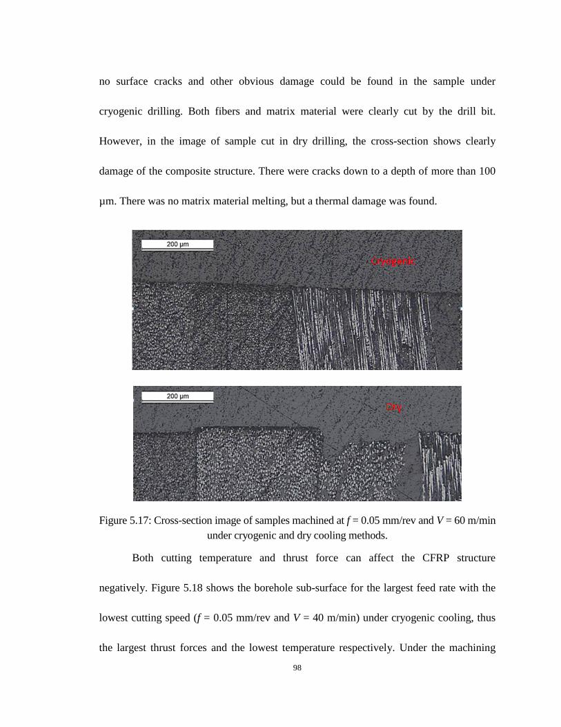
98
no surface cracks and other obvious damage could be found in the sample under
cryogenic drilling. Both fibers and matrix material were clearly cut by the drill bit.
However, in the image of sample cut in dry drilling, the cross-section shows clearly
damage of the composite structure. There were cracks down to a depth of more than 100
µm. There was no matrix material melting, but a thermal damage was found.
Figure 5.17: Cross-section image of samples machined at f = 0.05 mm/rev and V = 60 m/min under cryogenic and dry cooling methods.
Both cutting temperature and thrust force can affect the CFRP structure
negatively. Figure 5.18 shows the borehole sub-surface for the largest feed rate with the
lowest cutting speed (f = 0.05 mm/rev and V = 40 m/min) under cryogenic cooling, thus
the largest thrust forces and the lowest temperature respectively. Under the machining
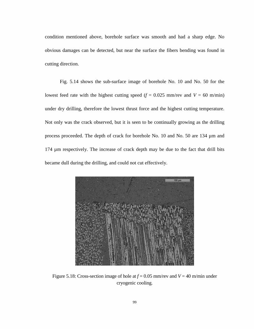
99
condition mentioned above, borehole surface was smooth and had a sharp edge. No
obvious damages can be detected, but near the surface the fibers bending was found in
cutting direction.
Fig. 5.14 shows the sub-surface image of borehole No. 10 and No. 50 for the
lowest feed rate with the highest cutting speed (f = 0.025 mm/rev and V = 60 m/min)
under dry drilling, therefore the lowest thrust force and the highest cutting temperature.
Not only was the crack observed, but it is seen to be continually growing as the drilling
process proceeded. The depth of crack for borehole No. 10 and No. 50 are 134 µm and
174 µm respectively. The increase of crack depth may be due to the fact that drill bits
became dull during the drilling, and could not cut effectively.
Figure 5.18: Cross-section image of hole at f = 0.05 mm/rev and V = 40 m/min under cryogenic cooling.
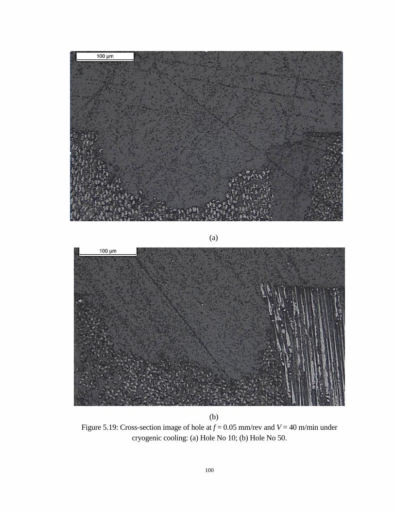
100
(a)
(b) Figure 5.19: Cross-section image of hole at f = 0.05 mm/rev and V = 40 m/min under
cryogenic cooling: (a) Hole No 10; (b) Hole No 50.

101
5.5 Surface Roughness
Figure 5.16 shows the surface roughness (Ra) at different cutting parameters under
dry and cryogenic conditions. Surface roughness ranges from 0.53 μm to 0.78 μm under
dry condition. The application of liquid nitrogen led to much better surface roughness.
The surface roughness is reduced from 0.35 μm to 0.23 μm after cryogenic drilling. A
large deviation of surface roughness is shown in dry drilling compared with cryogenic
drilling. The surface roughness of CFRP drilled hole could give some indication on the
level of damage of the produced hole in terms of fiber pullout, fiber fuzziness and crack.
Crack observed in the sub-surface of borehole machined under dry condition could be the
reason for poor surface finish in dry drilling. The results also could be correlated to the
tool-wear result presented in Chapter 3, since that machining with larger edge radius tools
increased the surface roughness as blunt tools induced more pushing and tearing of the
fiber and heat generation. Cryogenic cooling maintains the sharpness of the drill bit,
which led to a better surface finish. Both cutting speed and feed rate influence surface
roughness negatively although an increase in surface roughness is more significant with
the increase in feed rate.
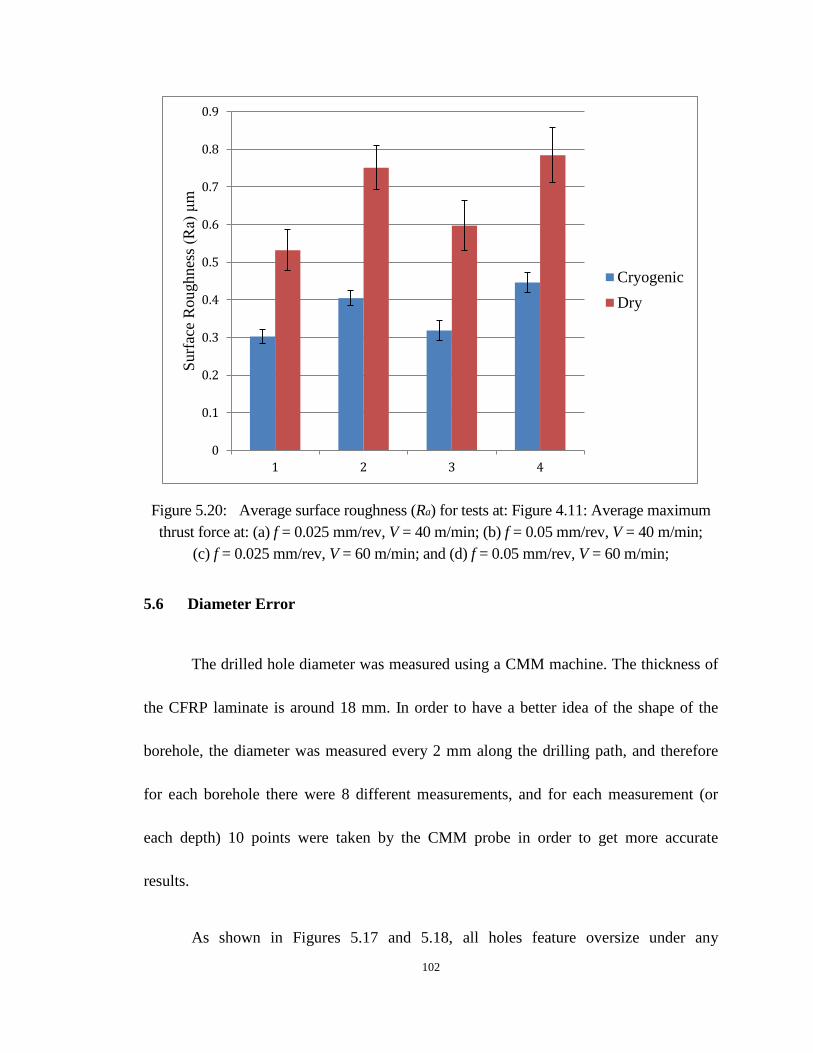
102
Figure 5.20: Average surface roughness (Ra) for tests at: Figure 4.11: Average maximum thrust force at: (a) f = 0.025 mm/rev, V = 40 m/min; (b) f = 0.05 mm/rev, V = 40 m/min;
(c) f = 0.025 mm/rev, V = 60 m/min; and (d) f = 0.05 mm/rev, V = 60 m/min;
5.6 Diameter Error
The drilled hole diameter was measured using a CMM machine. The thickness of
the CFRP laminate is around 18 mm. In order to have a better idea of the shape of the
borehole, the diameter was measured every 2 mm along the drilling path, and therefore
for each borehole there were 8 different measurements, and for each measurement (or
each depth) 10 points were taken by the CMM probe in order to get more accurate
results.
As shown in Figures 5.17 and 5.18, all holes feature oversize under any
0
0.1
0.2
0.3
0.4
0.5
0.6
0.7
0.8
0.9
1 2 3 4
Surf
ace
Rou
ghne
ss (R
a) μ
m
CryogenicDry

103
machining parameters. Borehole under dry condition tends to be larger since a higher
cutting temperature in dry drilling leads to more severe expansion of the drill bit. The
diameter of borehole continually increased, and then dropped after the drill went through
half of the thickness of the laminate, due to the barreling effect. On the contrary, borehole
under cryogenic drilling was closer to the drill diameter and more consistent, since liquid
nitrogen carried away a lot of heat, and thus the drill bit did not expend as much as in dry
drilling.
It is also noticeable that the diameter decreased with the increase of drill hole
number and borehole in cryogenic drilling declined less. This trend agrees with the
finding from tool-wear results presented in Chapter 4.
Figure 5.21: Diameter of boreholes at V = 60 m/min, f = 0.05 mm/rev, dry cooling condition.

104
Figure 5.22: Diameter of boreholes at V = 60 m/min, f = 0.05 mm/rev, cryogenic cooling condition.
5.7 Summary
The influences of drilling, under both dry and cryogenic conditions on several
aspects of hole quality and surface integrity, were investigated, including delamination,
burr generation, sub-surface damage, diameter error, and surface roughness. Major
observations can be summarized as follows:
Delamination in cryogenic drilling is more severe than in dry drilling due to the
higher thrust force. Delamination grows faster in dry drilling because of the rapid
increase in cutting edge radius. Back-up material has been proved to be a practical
approach to minimize delamination in cryogenic drilling to an acceptable level.
Excessive burr generation has been found in dry drilling due to the higher outer
105
corner wear.
Both thrust force and cutting temperature have influences on sub-surface quality.
Borehole under cryogenic cooling features sharp edge, without crack, but with fiber
bending; meanwhile, surface deviation, crack, and other thermal damage have been
found in borehole drilled under dry condition.
Surface Roughness (Ra) is significantly improved by cryogenic cooling for the reason
that liquid nitrogen not only can keep the sharpness of drill bit, but also helps to carry
away the heat generated in the drilling process to avoid thermal damage to the
surface.
Borehole under cryogenic drilling has less diameter error, because the diameter is
more consistent at every depth of the borehole. Also, because of the better tool-wear
performance, diameter of borehole under cryogenic drilling does not declines as
much as under dry condition.
106
CHAPTER 6: CONCLUSIONS AND FUTURE WORK
6.1 Summary of Present Work
In this thesis work, experimental studies on the influence of various machining
conditions (cooling methods and cutting parameters) on the drilling performance of
CFRP composite, including tool-wear performance, thrust force and torque, hole quality
and surface integrity of the borehole, etc., have been conducted. The benefits of
cryogenic cooling for machining metal were reported frequently in the literature, while
cryogenic drilling of CFRP laminate was barely investigated, and this is the main focus
for this research work.
In addition to the experimental work, an analytical approach for predicting the
critical thrust force for drilling operation has been carried out. The following major
conclusions can be drawn from this research work:
Significant reduction of cutting temperature by supplying liquid nitrogen through
coolant hole of the drill bit onto the tool-workpiece interface improves tool-wear
performance in cryogenic drilling, in terms of having a lower cutting edge radius and
outer corner wear compared with dry drilling. Increase of cutting speed and feed rate
led to marginal elevation of cutting edge radius and outer corner wear.
Both thrust force and torque were larger in cryogenic drilling than in dry drilling due

107
to the fact that cryogenic cooling increases the strength of the workpice and makes
the material harder to drill. Thrust force and torque increased with increasing feed
rate, meanwhile both thrust force and torque decreased with increasing cutting speed.
An analytical model has been used to predict critical thrust force. In order to achieve
borehole with no delamination, the applied thrust force should not exceed this value.
Delamination in cryogenic drilling is more severe than in dry drilling due to the
higher thrust force. Delamination grows faster in dry drilling because of the rapid
increase of cutting edge radius. Back-up material has been proven as a practical
approach to minimize delamination in cryogenic drilling to an acceptable level.
Excessive burr generation has been found in dry drilling due to higher outer corner
wear.
Both thrust force and cutting temperature have an influence on sub-surface quality.
Borehole under cryogenic cooling features sharp edge without crack, but with fiber
bending. Meanwhile, surface deviation, crack, and other thermal damage have been
found in borehole drilled under dry condition.
The application of liquid nitrogen dramatically improved surface roughness (Ra)
since cryogenic cooling is not only able to keep the sharpness of drill bit, but it also
carries away the heat generated in the drilling process to avoid thermal damage to the
surface.
Borehole under cryogenic drilling has less diameter error in terms of consistency of

108
hole diameter in different depth. It is also notable that the diameter of borehole under
cryogenic drilling does not decline as much as under dry condition
6.2 Future Work
There has been a substantial increase in the study of drilling of CFRP materials
recently, and it is a promising research area from the application point of view. Because
there are so many variables involved in drilling of CFRP material, countless research
could be conducted. Further research work in machining of CFRP materials could include:
the effects of drill bit grade and coatings, cutting temperature measurement, more
systematical study of the effect of cutting parameters on the drilling performance, etc.

109
REFERENCES
1. Komanduri R. 1997. Machining of fiber-reinforced composites. Machining Science and Technology 1:113-152.
2. Bhatnagar N, Naik NK, Ramakrishnan N. 1993. Experimetal investigation of drilling
on CFRP composites. Materials and Manufacturing Processes 8:683-701. 3. Teti R. 2002. Machining of composite materials. CIRP Annals - Manufacturing
Technology 51:611-634. 4. Brinksmeier E, Fangmann S, Rentsch R. 2011. Drilling of composites and resulting
surface integrity. CIRP Annals - Manufacturing Technology 60:57-60. 5. Franke V. 2011. Drilling of long fiber reinforced thermoplastics—Influence of the
cutting edge on the machining results. CIRP Annals - Manufacturing Technology 60:65-68.
6. Weinert K, Kempmann C. 2004. Cutting temperatures and their effects on the
machining behaviour in drilling reinforced plastic composites. Advanced Engineering Materials 6:684-689.
7. ASTM D3171–06. 2006. Standard test method for constituent content of composite
materials. Annual Book of ASTM Standards:80–86. 8. Faraz A, Biermann D, Weinert K. 2009. Cutting edge rounding: An innovative tool
wear criterion in drilling CFRP composite laminates. International Journal of Machine Tools and Manufacture 49:1185-1196.
9. Ho-Cheng H, Dharan CKH. 1990. Delamination during drilling in composite
laminates. Journal of Engineering for Industry 112:236-239. 10. Tsao CC. 2007. Thrust force and delamination of core-saw drill during drillin
of carbon fiber reinforced plastics (CFRP). International Journal of Advanced Manufacturing Technology 37:23-28.
11. El-Sonbaty I, Khashaba UA, Machaly T. 2004. Factors affecting the machinability of
GFR/epoxy composites. Composite Structures 63:329-338.

110
12. Khashaba UA. 2004. Delamination in drilling GFR-thermoset composites. Composite Structures 63:313-327.
13. Tsao CC, Hocheng H. 2004. Taguchi analysis of delamination associated with various
drill bits in drilling of composite material. International Journal of Machine Tools and Manufacture 44:1085-1090.
14. Hocheng H, Tsao CC. 2006. Effects of special drill bits on drilling-induced
delamination of composite materials. International Journal of Machine Tools and Manufacture 46:1403-1416.
15. Hocheng H, Tsao CC. 2003. Comprehensive analysis of delamination in drilling of
composite materials with various drill bits. Journal of Materials Processing Technology 140:335-339.
16. Fernandes M, Cook C. 2006. Drilling of carbon composites using a one shot drill bit.
Part I: Five stage representation of drilling and factors affecting maximum force and torque. International Journal of Machine Tools and Manufacture 46:70-75.
17. Tsao CC, Hocheng H. 2005. Effects of exit back-up on delamination in drilling
composite materials using a saw drill and a core drill. International Journal of Machine Tools and Manufacture 45:1261-1270.
18. Shyha IS, Soo SL, Aspinwall DK, Bradley S. 2011. The effect of peel ply layer on hole integrity when drilling carbon fibre-reinforced plastic. Proceedings of the Institution of Mechanical Engineers, Part B: Journal of Engineering Manufacture 225:1217-1223.
19. Won MS, Dharan CK. 2002. Chisel edge and pilot hole effects in drilling composite
laminates. American Society of Mechanical Engineers 124:232-245. 20. Wang X, Wang LJ, Tao JP. 2004. Investigation on thrust in vibration drilling of
fiber-reinforced plastics. Journal of Materials Processing Technology 148:239-244. 21. Hocheng H, Tsao CC. 2005. The path towards delamination-free drilling of
composite materials. Journal of Materials Processing Technology 167:251-264. 22. Tsao CC, Hocheng H, Chen YC. 2012. Delamination reduction in drilling composite
materials by active backup force. CIRP Annals - Manufacturing Technology 61:91-94.

111
23. Ramulu M, Faridnia M, Garbini JL, Jorgensen JE. 1991. Machining of graphite/epoxy composite materials with polycrystalline diamond (PCD) tools. Journal of Engineering Materials and Technology 113:430-436.
24. Davim JP, Reis P. 2003. Study of delamination in drilling carbon fiber reinforced
plastics (CFRP) using design experiments. Composite Structures 59:481-487. 25. Ramulu M, Young P, Kao H. 1999. Drilling of graphite/bismaleimide composite
material. Journal of Materials Engineering and Performance 8:330-338. 26. Durão LMP, Gonçalves DJS, Tavares JMRS, de Albuquerque VHC, Aguiar Vieira A,
Torres Marques A. 2010. Drilling tool geometry evaluation for reinforced composite laminates. Composite Structures 92:1545-1550.
27. Tsao CC, Hocheng H. 2003. The effect of chisel length and associated pilot hole on
delamination when drilling composite materials. International Journal of Machine Tools and Manufacture 43:1087-1092.
28. Shyha IS, Aspinwall DK, Soo SL, Bradley S. 2009. Drill geometry and operating
effects when cutting small diameter holes in CFRP. International Journal of Machine Tools and Manufacture 49:1008-1014.
29. Harris SG, Doyle ED, Vlasveld AC, Audy J, Quick D. 2003. A study of the wear
mechanisms of Ti1−xAlxN and Ti1−x−yAlxCryN coated high-speed steel twist drills under dry machining conditions. Wear 254:723-734.
30. Harris SG, Doyle ED, Vlasveld AC, Audy J, Long JM, Quick D. 2003. Influence of
chromium content on the dry machining performance of cathodic arc evaporated TiAlN coatings. Wear 254:185-194.
31. Abu-Mahfouz I. 2003. Drilling wear detection and classification using vibration
signals and artificial neural network. International Journal of Machine Tools and Manufacture 43:707-720.
32. Mohan NS, Ramachandra A, Kulkarni SM. 2005. Influence of process parameters on
cutting force and torque during drilling of glass–fiber polyester reinforced composites. Composite Structures 71:407-413.

112
33. Palanikumar K. 2007. Modeling and analysis for surface roughness in machining glass fibre reinforced plastics using response surface methodology. Materials & Design 28:2611-2618.
34. Shyha I, Soo SL, Aspinwall D, Bradley S. 2010. Effect of laminate configuration and
feed rate on cutting performance when drilling holes in carbon fibre reinforced plastic composites. Journal of Materials Processing Technology 210:1023-1034.
35. Shyha IS, Soo SL, Aspinwall DK, Bradley S, Perry R, Harden P, Dawson S. 2011.
Hole quality assessment following drilling of metallic-composite stacks. International Journal of Machine Tools and Manufacture 51:569-578.
36. Park K-H, Beal A, Kim D, Kwon P, Lantrip J. 2011. Tool wear in drilling of
composite/titanium stacks using carbide and polycrystalline diamond tools. Wear 271:2826-2835.
37. Park K-H, Kwon P, Kim D. 2012. Wear characteristic on BAM coated carbide tool in
drilling of composite/titanium stack. International Journal of Precision Engineering and Manufacturing 13:1073-1076.
38. Bhattacharyya D, Horrigan DPW. 1998. A study of hole drilling in Kevlar composites.
Composites Science and Technology 58:267-283. 39. Ahmed M. 2004. Cryogenic drilling of Kevlar composite laminated. M.S. Thesis,
Mechanical Engineering, King Fahd University of Petroleum and Minerals. 40. Kim D, Ramulu M. 2004. Cryogenically treated carbide tool performance in drilling
thermoplastic composites. Transactions of NAMRI/SME, 32:79-85. 41. Yang S, Dillon OW, Puleo DA, Jawahir IS. 2013. Effect of cryogenic burnishing on
surface integrity modifications of Co-Cr-Mo biomedical alloy. Journal of Biomedical Materials Research Part B: Applied Biomaterials 101B:139-152.
42. Rotella G, Dillon OW, Jr., Umbrello D, Settineri L, Jawahir IS. 2014. The effects of
cooling conditions on surface integrity in machining of Ti6Al4V alloy. International Journal of Advanced Manufacturing Technology 71:47-55.

113
43. Pu Z, Outeiro JC, Batista AC, Dillon Jr OW, Puleo DA, Jawahir IS. 2012. Enhanced surface integrity of AZ31B Mg alloy by cryogenic machining towards improved functional performance of machined components. International Journal of Machine Tools and Manufacture 56:17-27.
44. Davies MA, Ueda T, M'Saoubi R, Mullany B, Cooke AL. 2007. On the measurement
of temperature in material removal processes. CIRP Annals - Manufacturing Technology 56:581-604.
45. Dörr J, Mertens T, Engering G, Lahres M. 2003. ‘In-situ’ temperature measurement
to determine the machining potential of different tool coatings. Surface and Coatings Technology 174:389-392.
46. Jawahir IS, Brinksmeier E, M'Saoubi R, Aspinwall DK, Outeiro JC, Meyer D,
Umbrello D, Jayala AD. 2011. Surface integrity in material removal processes: Recent advances. CIRP Annals - Manufacturing Technology 60:603-626.
47. Tsao C-C, Chen W-C. 1997. Prediction of the location of delamination in the drilling
of composite laminates. Journal of Materials Processing Technology 70:185-189. 48. Saghizadeh H, Dharan CK. 1986. Delamination fracture toughness of graphite and
aramid epoxy composites, Journal of Manufacturing Science Engineering 108: 290-295.
49. Timoshenko S, Woinowsky S. 1959. Theory of plates and shells, 2nd ed.
McGraw-Hill:51-72. 50. Won MS, Dharan CK. 2002. Drilling of aramid and carbon fibre polymer composites,
Journal of Manufacturing Science Engineering 124:778–783. 51. Shaw MC, Oxford CJ. 1959. On the drilling of metals 2-the torque and thrust in
drilling, Transactions of the ASME (1957):139-148. 52. Fernandes M, Cook C. 2006. Drilling of carbon composites using a one shot drill bit.
Part II: empirical modeling of maximum thrust force. International Journal of Machine Tools and Manufacture 46:76-79.
53. Gururaja S, Ramulu M. 2009. Modified exit-ply delamination model for drilling FRPs,
Journal of Composite Materials 5:483-500.

114
54. Reed RP, Golda M. 1994. Cryogenic properties of unidirectional composites. Cryogenics 34:909-928.
55. Reed RP, Golda M. 1997. Cryogenic composite supports: a review of strap and strut
properties. Cryogenics 37:233-250. 56. Kim RY, Donaldson SL. 2006. Experimental and analytical studies on the damage
initiation in composite laminates at cryogenic temperatures. Composite Structures 76:62-66.
57. Rawat S, Attia H. 2009. Characterization of the dry high speed drilling process of
woven composites using Machinability Maps approach. CIRP Annals - Manufacturing Technology 58:105-108.
58. Rawat S, Attia H. 2009. Wear mechanisms and tool life management of WC–Co
drills during dry high speed drilling of woven carbon fibre composites. Wear 267:1022-1030.
59. Gordon S, Hillery MT. 2003. A review of the cutting of composite materials.
Proceedings of the Institution of Mechanical Engineers, Part L: Journal of Materials Design and Applications 217:35-45.

115
VITA
The author was born in Changchun, China. He received his Bachelor’s Degree from
Northeast Forestry University, China in 2009. He pursued his Master’s Degree at
Mechanical Engineering Program of the University of Kentucky.