INVESTIGATION OF CATASTROPHIC FRACTURING AND …...INVESTIGATION OF CATASTROPHIC FRACTURING AND...
37
OCT 20 64 NASA TECHNICAL MEMORANDUM NASA TM X - 52063 INVESTIGATION OF CATASTROPHIC FRACTURING AND CHEMICAL REACTIVITY OF LIQUID-FILLED TANKS WHEN IMPACTED BY PROJECTILES OF HIGH VELOCITY by Francis S. Stepka, Robert P. Dengler, and C. Robert Morse Lewis Research Center Cleveland, Ohio TECHNICAL PREPRINT prepared for Seventh Hy- pervelocity Impact Symposium Sponsored by the Tri-Service Committee on Hypervelocity Impact Tampa, Florida, November 17-19, 1964 NATIONAL AERONAUTICS AND SPACE ADMINISTRATION • WASHINGTON, D.C. • 1964
Transcript of INVESTIGATION OF CATASTROPHIC FRACTURING AND …...INVESTIGATION OF CATASTROPHIC FRACTURING AND...

OCT 20 6 4
N A S A T E C H N I C A L M E M O R A N D U M
NASA TM X - 52063
INVESTIGATION OF CATASTROPHIC FRACTURING AND CHEMICAL REACTIVITY OF LIQUID-FILLED TANKS WHEN IMPACTED BY PROJECTILES OF HIGH VELOCITY
by Francis S. Stepka, Robert P. Dengler, and C. Robert Morse Lewis Research Center Cleveland, Ohio
TECHNICAL PREPRINT prepared for Seventh Hy-pervelocity Impact Symposium Sponsored by the Tri-Service Committee on Hypervelocity Impact Tampa, Florida, November 17-19, 1964
NATIONAL AERONAUTICS AND SPACE ADMINISTRATION • WASHINGTON, D.C. • 1964

INVESTIGATION OF CATASTROPHIC FRACTURING AND CHEMICAL
REACTIVITY OF LIQUID-FILLED TANKS WHEN IMPACTED
BY PROJECTILES OF HIGH VELOCITY
by Francis S. Stepka, Robert P. Dengler, and C. Robert Morse
Lewis Research Center Cleveland, Ohio
TECHNICAL PREPRINT prepared for
Seventh Hypervelocity Impact Symposium sponsored by the Tri-Service Committee on Hypervelocity Impact
Tampa, Florida, November 17-19, 1964
NATIONAL AERONAUTICS AND SPACE ADMINISTRATION

IMPACTS INTO LIQUID-FILLED TANKS
ABSTRACT
The effects of some of the primary variables contributing to bursting or catastrophic fracturing of liquid-filled tanks due to impacts are presented. Also presented is the sensitiv-ity to chemical reaction as a result of projectile impact on tank wall materials with contained propellants.
Projectiles of different materials primarily spheres 1/16 to 7/32 inch in diameter accelerated to velocities from about 750 to 21,000 ft/sec were impacted into sheet test specimens attached to and acting as a wall of a liquid-filled tank. The specimens were sheets of 0.020- to 0.125-inch-thick aluminum, stainless-steel, and titanium alloys and three reinforced plas-tics. The contained liquids were water, glycerine, nitrogen, oxygen, hydrazine, unsymmetrical dimethylhydrazine, and nitro-gen tetroxide.

INTRODUCTION
An impact by a meteoroid of sufficient energy into a liquid-propellant tank wall may result in bursting or catas-trophic rupturing of the wall rather than a simple puncture. The fracturing of the wall may be caused by transient stresses induced in the tank wall as a result of the shock pressure gen-erated in the liquid propellant by the decelerating particle. In addition, the possibility of a chemical interaction of the tank-wall material and the propellant as a result of the energy imparted by the impacting meteoroid also exists.
Considerable research, both experimental and analytical, has been conducted on the penetration mechanism of high-speed projectiles. This research1,2 was concentrated mostly on thick, unstressed targets and bumper protection systems with unstressed walls. Previous investigations have not studied the combined effects of high-velocity impact on either stress or unstressed walls in contact with a liquid.
Initial experimental evidence3,4,5,6,7 of a possible haz-ard of a chemical reaction of tank-wall material and propellant as a result of meteoroid impact was indicated by drop-impact tests on a large number of material-oxidant combinations. The results of these tests, wherein a plummet impacted a striker pin in contact with material specimens submerged in the liquid oxidant, indicated that, for a titanium - liquid-oxygen combi-nation, violent explosive and/or pyrophoric reactions occurred, even at impact energies as low as 7 foot-pounds. In addition, reactions were obtained with many types of plastic materials.
The importance of determining conditions that can lead to catastrophic failure of a propellant tank and/or reaction of the tank wall and contained propellant when impacted by small, high-velocity projectiles or meteoroids is apparent from the preceding discussion. This paper presents a summary of results from investigations at the Lewis Research Center8,9 directed at understanding some of the factors involved. More recent data at impact velocities higher than those reported in these in-vestigations are also presented.
In these investigations, various tank-wall materials in contact with various liquids or propellants are impacted by small, high-velocity projectiles. The projectiles were pri-marily spheres of various materials with diameters from 1/16 to 7/32 inch. A range of projectile velocities from about 750 to 21,000 feet per second was investigated.
APPARATUS AND PROCEDURE
Most of the impacts into liquid-filled tanks reported herein were conducted at the Lewis Research Center with a high-speed rifle and a light-gas gun. The other impacts were con-ducted with a light-gas gun at the Utah Research and Develop-ment Company under contract to the NASA. Figure 1 is a sche-matic drawing of the apparatus involved in the impact tests conducted with the high-speed rifle. The velocities of pro-jectiles accelerated by the rifle were measured by electronic-pulse outputs from two stations of electrically charged 0.25-mil aluminized Mylar located a fixed distance apart. Projec-tile velocities for the light-gas gun at Lewis (fig. 2) were obtained from electronic-pulse outputs produced by the action of the projectile interrupting a light screen at each of two stations located a fixed distance apart. Photographs of the projectile in flight at each of these stations were obtained by a spark-gap light source, Kerr cell, and camera combination. The velocities of the projectiles accelerated with the light-gas gun at the Utah Research and Development Company were de-termined from the time of successive flashes produced first at the end of the gun barrel and then from impact at the tank wall.
Two types of tanks were employed in the investigations. One type was a cylindrical metal tank design (figs. 3 and 4) with one end removable and easily replaced. These ends consti-tuted the test specimens to be impacted. This type of tank permitted the investigation of the factors affecting wall frac-ture and/or possible chemical reactions of different tank-wall materials and contained propellants. The active test section of the test specimens on the tanks to study the wall-fracture problem was a disk 11 inches in diameter. The specimens on the tanks to study the chemical reactivity problem were 5 inches in diameter.
The other type of tank used in the investigation was rec-tangular in shape and was made from transparent plastic, except for one removable sheet-metal end, which acted as the test specimen to be impacted. This type of tank was used in con-junction with a high-speed framing camera to provide informa-tion on the shock waves that were generated in the liquid with-in the tank and also to provide photographic records of the im-pact into, and the progress of the fracturing of, the metal wall.
According to the test procedure, individual projectiles were fired into the test specimen attached to the liquid-filled test tanks, and observations were made to determine whether the specimen was only punctured or whether a fracture resulted.
For the tests of impact sensitivity to chemical reaction, the impacts were observed and the tank-wall specimens subsequently examined to determine whether any chemical interaction of the tank-wall material and contained propellant occurred. A high-speed framing camera recorded the results of a larger number of these impacts.
The specimen materials used for the study of the problem of the catastrophic fracture of tank walls from impact were 1/32- and 1/16-inch-thick sheets of 2014-T6 and 7075-T6 alumi-num alloys and 1/32 -inch-thick sheets of AISI 301 stainless steel with a 60-percent cold reduction. Tank-wall specimens were tested in both the unstressed condition (no initial static stress) and in the prestressed condition (having an initial static stress equal to 0. 2 percent offset yield strength of the material). The initial static tank-wall stresses were induced by appropriate pressurization of the tank. Liquids investiga-ted in this study were water, glycerine, and nitrogen. The im-pacting projectiles were primarily spheres of aluminum, nylon, steel, and tungsten carbide ranging in size from 1/16 to 7/32 inch in diameter. Impact velocities ranged from 1650 to 21,000 feet per second.
The tank-wall materials investigated in the study of im-pact sensitivity to chemical reaction of wall-material - pro-pellant combinations were aluminum (6061-T3), stainless steel (AISI 304), titanium (5A1-2.5Sn-Ti and 6A1-4V-Ti), and three reinforced plastics (Dacron-fiber-reinforced polyurethane, nylon-cloth-reinforced phenolic resin, and glass-cloth-reinforced epoxy resin). The thicknesses of the tank wall spe-cimens ranged from 0.020 to 0.125 inch. Propellants investiga-ted in this study included the liquids, oxygen, nitrogen tetrox-ide, hydrazine, and unsymmetrical dimenthylhydrazine. The im-pacting projectiles were spheres of aluminum, nylon, and steel varying in size from 1/16 to 7/32 inch in diameter. Impact velocities for these tests ranged from 756 to 20,400 feet per second.
FACTORS AFFECTING FRACTURE Prior to conducting the experimental phase of the investi-
gation, an analysis was made of the impact process into liquid-filled tanks to determine factors that may contribute to wall fracture. A description of the impact process and a summary of the factors expected to affect wall fracture are presented in the following paragraphs.
When a high-velocity projectile impacts a tank wall in contact with a liquid, dynamic stresses are first induced in the wall by the cratering and puncturing action of the projec-tile. The cratering action induces radial compressive and cir-

cumferential tensile stresses in the wall. After penetrating the wall, the elastic strain energy absorbed in the cratering processes is released, and radial-tensile and circumferential-compressive stresses are induced. The puncturing action in-duces dynamic flexural stresses in the wall due to the resis-tance to shearing offered by the wall. After the projectile has penetrated the wall and has impacted into the contained liquid, part of the kinetic energy or momentum of the projec-tile is converted into a pressure wave in the liquid that ema-nates from the point of impact. This pressure wave induces additional stresses in the tank wall. These stresses, when combined with those induced by the cratering action and punc-turing of the wall, plus any static stress in the wall due to initial tank pressurization, may be large enough to result in catastrophic fracture of the tank wall. In addition, a region of high-stress concentration is present at the edge of the hole.
The factors affecting the stresses induced in the tank wall of a given thickness and material impacted by a high-speed projectile are summarized in figure 5. The dynamic stresses in the wall due to impact and penetration are indi-cated to be functions of the projectile velocity, material and/or density, size and shape. These factors, however, may possibly be grouped together into parameters such as projectile kinetic energy or momentum. The stresses in the wall due to the liquid pressure are functions of liquid static pressure, density, and velocity of sound, plus projectile velocity, ma-terial and/or density, size and shape. These factors may also be grouped together into parameters such as projectile kinetic energy or momentum and liquid compressibility. In addition to these factors, the catastrophic fracture of a tank wall of a given material would be affected by the amount of cold work and heat treatment, the material strength properties at the high rates of loading imposed by the impact and at the temperature of the contained liquid. Fracture would also be influenced by the shape and size of the hole and/or microcracks at the edge of the hole resulting from the impact.
WALL FRACTURE CAUSED BY IMPACTS
The previous section indicated that a large number of factors can contribute to the catastrophic bursting of a tank wall impacted by a small, high-velocity projectile. A complete study of these factors and their combined effect is beyond the scope of this paper. The investigation described here was con-ducted to determine the extent of damage expected from impact by small, high-velocity projectiles into liquid-filled tanks and to provide an insight into the effects of only some of the more important factors affecting fracture. The data at condi-
tions of impact and fracture for each of the materials and thicknesses of the tank walls and for each contained liquid will be presented by using projectile parameters that appear significant, that is, projectile velocity and kinetic energy, size and material. Subsequent analyses may very well indicate more satisfactory parameters for the presentation of the data. It is felt, however, that presentation of these data, in es-sentially raw form, by using these parameters rather than wait-ing until an adequate model is developed for correlating the data or predicting the failure, is warranted because of current interest in the results of this investigation.
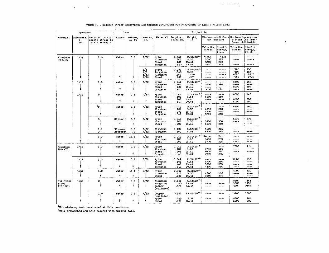
A summary of the minimum projectile impact velocities and kinetic energies required to fracture specimens is presented in Table I. Fracture of some test specimens did not occur even at the maximum capabilities of the high-speed rifle employed. For these cases, the maximum values of velocity and kinetic energy for which impacts were made without resulting in frac-ture are presented. In addition to the results of the tests listed in Table I, preliminary results of impacts made at higher velocities (up to 21,000 ft/sec) will be discussed in the subsequent sections.
Aluminum Specimens on Water-Filled Tank
A typical puncture and some typical fractures resulting from impacts of aluminum specimens on water-filled tanks are shown in figure 6. Examination of the fracture indicated that the plane of the fractures was generally at 45° to the plane of the specimen wall, indicating a shear failure. Many impacts were made into aluminum specimens by using projectiles of vari-ous sizes and materials to provide data so that the effect of the projectile parameters on the fracturing of the specimen could be determined. Data shown in figure 7 indicate that for impacts with 7/32-inch-diameter metal spheres (aluminum, steel, and tungsten carbide), there was a critical velocity below which only a puncture of the specimen resulted and above which a catastrophic fracture occurred. In addition, these data in-dicate that, as the density of the projectile decreased, a higher impact velocity was required to fracture the tank wall; however, the corresponding projectile kinetic energies de-creased with projectile density. The critical velocities for the 7/32-inch spheres of tungsten carbide, steel, and aluminum impacting a stressed 1/32-inch-thick aluminum (7075-T6) speci-men, as can be seen in figure 7, were 2850, 3300, and 5000 feet per second with corresponding projectile kinetic energies of 375, 260, and 215 foot-pounds. These velocities and energies are considerably greater than those required for simple punc-turing of the specimens on a water-filled tank.

The data for 7/32-inch-diameter nylon spheres impacting into prestressed 7075-T6 aluminum specimens on a water-filled tank (fig. 7) indicate that ruptures of tank-wall specimens were obtained over the entire range of velocities investigated (1650 to 7000 ft/sec). Analysis of results from these shots and the examination of the fractured specimens have shown that ruptures at the low velocities were not due to the pressure forces generated in the water but were due to the tearing ac-tion on the wall by these projectiles. Additional verification of this conclusion was obtained from impacts into pressurized gas-filled tanks, the results of which are discussed in a later section.
Impacts with smaller projectiles, that is, 1/8-inch tung-sten carbide, 1/16- and 1/8-inch steel, and 3/32-inch aluminum spheres, launched with the high-speed rifle, did not result in fracture of the tank wall even at velocities as high as 7180 feet per second. This was the maximum capability of the rifle used. Preliminary results of impacts with small projectiles launched with a light-gas gun at velocities as high as 21,000 feet per second indicated that fractures of even unstressed 1/32-inch-thick aluminum specimens on a water-filled tank oc-
curred with 1/8-inch-aluminum and 1/16-inch-steel spheres. The data obtained with aluminum spheres further indicate that, although the velocity required to produce a fracture increases as the diameter decreases, the associated projectile kinetic energy decreases. For example, the impact velocity required to fracture an unstressed 1/32-inch-thick 7075-T6 aluminum speci-men increased by a factor of almost 2 as the aluminum-projectile diameter decreased from 7/32 to 1/8 inch, while the impact energy at critical velocity for the smaller projectile was less than one-half that of the larger projectile. This can be attributed, at least in part, to the fact that the pressure rise in the liquid is a function of the projectile velocity. Also, as the projectile velocity is increased, fragmentation of the projectile occurs, and a more rapid deceleration of the projectile takes place, thereby generating higher pressures in the liquid.
In addition to the impact conditions affecting the frac-ture of the tank wall, the data in Table I indicate that the tank-wall initial static stress level and thickness also have an effect. The effect of initial static wall stress was signi-ficant, since fractures of some of the unstressed walls could not be obtained even though the impact velocities were almost twice that required to fracture the stressed specimens. Dou-bling the thickness of the stressed specimens from 1/32 to 1/16 inch required an increase of about 9 to 48 percent in impact velocity to cause a fracture, depending on the specimen alloy and the projectile material.
Aluminum Specimens on Glycerine or Liquid-Nitrogen-Filled Tank
The results of the previous section demonstrated the ex-tent of fracture damage that is obtained from impact by small, high-velocity projectiles and primarily evaluated the effect of projectile-impact conditions on fracture. The effect of the contained liquid was not evaluated. Inasmuch as the rate of deceleration of the impacting projectile in the contained liq-uid would he expected to be related to the rate of energy transfer and pressure rise in the liquid, an evaluation of the effect of the contained liquids on fracture was undertaken. It would be expected that liquids with higher densities and lower compressibilities would produce higher pressures as a result of impacts with a given projectile material, size, and velocity. Glycerine, which is approximately half as compressible and 1.25 times as dense as water, was one of the liquids used in this study. The results shown in Table I indicate, as would be expected, that lower impact velocities were required to frac-ture the specimens on a glycerine-filled tank compared with those on a water-filled tank. The velocities required to frac-ture a 1/32-inch-thick 7075-T6 aluminum sheet with a 7/32-inch-diameter aluminum sphere were not much different though for these two liquids, that is, 6200 and 5900 feet per second for the water- and glycerine-filled-tanks, respectively. Examina-tion of the specimens after impact indicated that the fracture patterns were similar to those obtained on the water-filled tank but that the deformation of the specimens was somewhat greater than that obtained for the water-filled tank.
The other liquid used in the study was nitrogen, which is about 0.8 times as dense and 3.5 times as compressible as water. The results shown in Table I indicate that, as would be expected, the projectile velocity required to fracture the tank wall was higher than that for a specimen on a water-filled tank. The effect of low temperature of the liquid nitrogen (-320° F), however, on the properties of the specimen material, such as ultimate strength, ductility, and notch strength, is present also. For the liquids evaluated, the densities varied by a factor of about 1.6 and the compressibility by a factor of about 7. The data from these liquids indicate that the veloc-ity required to fracture the tank wall varied by a factor of 1.35.
Cryogenic liquids of interest for space applications are oxygen and hydrogen. Oxygen is about 1.4 times as dense and about 0.66 times as compressible as liquid nitrogen. It would be expected that the velocity required to fracture a liquid-oxygen-filled tank would be slightly less than that for a liquid-nitrogen-filled tank. For liquid hydrogen, which is 0.087 times as dense and over 6 times more compressible than liquid nitrogen; however, the velocity required to fracture a
tank of this liquid may be considerably greater than that re-quired for liquid-nitrogen.
Typical fractures of the stressed and unstressed 1/32-inch-thick 7075-T6 aluminum specimens on a liquid-nitrogen-filled tank as obtained from impact by 7/32-inch-diameter spheres are shown in figure 8. Comparison with figure 6 shows that a much more severe fracturing of the stressed specimens was evident when the contained fluid was liquid nitrogen. There was often a complete rupturing of the specimens. Exami-nation of the fractures indicated a brittle-type fracture, as evidenced by the fracture plane being perpendicular to the plane of the specimen wall.
Stainless-Steel Specimens on Water-Filled Tank
In order to evaluate the effect of another wall material, 1/32 -inch-thick 60-percent cold-reduced AISI 301 stainless-steel specimens on a water-filled tank were impacted. The re-sults of impact with various projectiles at the maximum condi-tions of the high-speed rifle, shown in Table I, could not pro-duce a fracture of either stressed or unstressed walls. Im-pacts by 7/32-inch aluminum spheres launched with the light-gas gun at a velocity of 14,000 feet per second, however, pro-duced a catastrophic fracture of an unstressed wall. An im-pact at a velocity of 13,000 feet per second produced only a puncture. The results shown in Table I indicate that the velocity of impact to fracture the same thickness of 7075-T6 aluminum specimen under the same test conditions (tank walls not prestressed and by using same projectile size and material) was only 6200 feet per second.
Specimens on Gas-Filled Tank
Impacts were made into stressed 1/32-inch-thick 7075-T6 aluminum specimens on a gaseous-nitrogen-filled tank in order to determine whether fracture of pressurized gas-filled tanks would occur. The tests were also made to demonstrate that the fractures of the stressed specimens on water-filled tanks were primarily due to the pressures generated in the liquid as a re-sult of the impacting projectile being decelerated by the liq-uid. The results of impacts made with 7/32-inch aluminum spheres indicated that no fractures of the wall occurred over the range of velocities investigated, from 2500 to 7200 feet per second. Impacts made with 7/32-inch nylon spheres at high velocities (about 7200 ft/sec) also resulted in penetrations without fracturing. When impacts were made with nylon spheres at velocities of 3500 feet per second and lower, however, a

catastrophic-type fracture did occur. Examination of the im-pact region of the specimens for these tests indicated that an inward petaling and tearing of the wall rather than a clean puncturing had occurred. These results indicate that, for a gas-filled tank, the high-velocity puncturing process, in it-self, would not be expected to cause a rupture of the tank wall, but that, if in the process of puncturing the tank wall, local tearing or enlargement of the hole is obtained such as to result in a critical crack length, a catastrophic rupture of the tank would occur.
CHARACTERISTICS OF PRESSURE PULSE IN LIQUID DUE TO IMPACT
The previous sections have determined the contributions of some of the controllable physical factors influencing the fracturing of liquid-filled tanks impacted by high-speed pro-jectiles. The results obtained do not provide information on, or the understanding of, the characteristics of the pressure pulse generated in the liquid. In order to obtain an insight into the characteristics of this pressure pulse and its in-fluence on fracture, measurements were made of the progress, duration, and magnitude of the pulse.
The measurements of pressure were obtained by two meth-ods. One method used a high-speed camera for obtaining shadow-graphs of the progress of the shock front as viewed through the sides of a water-filled transparent plastic tank. From the shadowgraph (a sequence Is shown in fig. 9), the velocity of the shock front was determined. This velocity, together with the relation10 of velocity and pressure, determined the pressure at the shock front as it moved away from the point of impact. The other method for obtaining pressure was to use piezo-electric-crystal pressure pickups mounted in the liquid near the point of impact. The output of these pickups indi-cated the local pressure in the water. In some tests, the projectiles were impacted into the 1/32-inch-thick sheets of aluminum that were used to form the front face or wall of the plastic test tank. In other tests the projectiles were im-pacted directly into the water through a prepunched hole in the aluminum wall. When impacts were made through prepunched holes, the holes were covered with masking tape or a thin plastic membrane in order to contain the liquid in the tank.
The results of impacts with 7/32-inch-diameter aluminum spheres at velocities between 6000 to 7500 feet per second in-dicate that pressures at the shock front between 70,000 to 120,000 psi are generated within 0.6 inch from the point of impact. These pressures decayed rapidly, however, and ap-proached ambient pressures within approximately 5 inches from
the point of impact. Measurement of the pressure of the pass-ing shock wave by the pressure pickups located 1.44 inches from the impact point indicated that pressures of about 3000 psi were obtained about 7.5 microseconds after passage of the wave front. The pressures decayed rapidly to 200 psi within about 40 microseconds and began to approach ambient conditions. The pickups did not disclose any additional pulses of significance at later times after passage of the pressure front. This would indicate that there are no reflected pressure waves from the rear or side wall of the tank that are of significance and that the initial pulse generated by impact is responsible for the fracturing of the specimens. Recent data with a light-gas gun indicated that pressures as high as 750,000 psi were generated at about 0.6 inch from the tank wall when impacted with a 0.9-gram steel projectile at a velocity of only 14,000 feet per second.
EFFECT OF TANK SIZE
Based on the results presented in the previous section, it would be expected that the initiation of the fracture of the test specimens would occur within the time duration of the pressure pulse. To verify this, a sequence of high-speed pho-tographs, taken approximately 4 microseconds apart, were made of the impact into, and the resulting fracture of, a 1/32-inch-thick aluminum specimen. Several selected photographs of the event are shown in figure 10. Examination of the photographs indicated a fracture approximately 27 microseconds after im-pact. The photographs for later times show the progress of the fracturing and eruption of the water from the tank. In the time of 27 microseconds, the shock front generated in the water would have advanced only about 2.5 inches away from the point of impact. This would indicate that only the volume of the tank contained within the hemispherical wave front, having a radius of a few inches, is aware that impact and fracturing of the specimen has occurred and that the pressure rise and the resulting damaging forces that cause fracturing of the speci-men are local phenomena and essentially independent of tank size.
As further verification that fracture is independent of tank size, impacts were made into a tank larger than the 12-inch-diameter and 9-inch long (volume, 0.6 cu ft) tank used in all the tests described previously. The large test tank was about 30 inches in diameter and 37 inches long and had a volume of 15.1 cubic feet. The investigation was conducted using stressed 1/32-inch-thick 7075-T6 and 2014-T6 aluminum specimens attached to this tank containing water. The results shown in Table I indicate no significant effect of tank size.

In order to determine whether the times to failure were significantly different for different conditions, impacts were made into two different thicknesses (1/32 and 1/16 in.) of aluminum on the water-filled tank and for a 1/32-inch aluminum specimen on a tank filled with liquid nitrogen. The times to fracture were indicated as 27, 33, and 40 microseconds, re-spectively; however, the times could have been less because observation of the cracks at earlier times is somewhat ob-scured by the rays of liquid spray. Also, for the nitrogen-filled tank, the frost layer on the wall surface made earlier detection of the crack difficult.
INTERACTION OF TANK-WALL MATERIALS AND PROPELLANTS RESULTING
FROM HIGH-VELOCITY IMPACTS
Table II presents a summary of the chemical reactivity of various combinations of rocket propellants and tank wall ma-terials when impacted by high velocity projectiles. The fol-lowing sections of this paper discuss the results of these im-pacts; the sections being categorized according to the pro-pellants contained within the tanks. The test numbers re-ferred to in the following sections are those listed in Table II.
Liquid Oxygen
The tank-wall materials investigated with the propellant liquid oxygen were titanium, reinforced plastics, aluminum, and stainless steel.
Titanium. - Because they are lightweight and possess high-strength properties, the titanium alloys are very de-sirable materials for fabricating propellant tanks for space applications. In addition to these high strength-to-weight characteristics, some titanium alloys exhibit excellent notch-strength properties at the cryogenic temperature of liquid oxygen (-297° F) compared with conventional tank-wall materials such as aluminum and stainless steel. The impor-tance of determining the sensitivity to high-velocity im-pact of titanium tank walls in contact with liquid oxygen is apparent.
Impact tests conducted on titanium tank walls in contact with liquid oxygen covered a range of test conditions with nylon, aluminum, and steel spheres being accelerated to veloc-ities between 756 and 6500 feet per second, which produced ki-
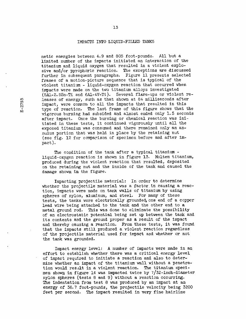
netic energies between 4.9 and 805 foot-pounds. All but a limited number of the impacts initiated an interaction of the titanium and liquid oxygen that resulted in a violent explo-sive and/or pyrophoric reaction. The exceptions are discussed further in subsequent paragraphs. Figure 11 presents selected frames of a motion-picture sequence that is typical of the violent titanium - liquid-oxygen reaction that occurred when impacts were made on the two titanium alloys investigated (5A1-2.5Sn-Ti and 6A1-4V-Ti). Several flare-ups or violent re-leases of energy, such as that shown at 84 milliseconds after impact, were common to all the impacts that resulted in this type of reaction. The last frame of this figure shows that the vigorous burning had subsided and almost ended only 1.5 seconds after impact. Once the burning or chemical reaction was ini-tiated in these tests, it continued vigorously until all the exposed titanium was consumed and there remained only an an-nulus portion that was held in place by the retaining nut (see fig. 12 for comparison of specimen before and after im-pact).
The condition of the tank after a typical titanium -liquid-oxygen reaction is shown in figure 13. Molten titanium, produced during the violent reaction that resulted, deposited on the retaining nut and the inside of the tank and caused the damage shown in the figure.
Impacting projectile material: In order to determine whether the projectile material was a factor in causing a reac-tion, impacts were made on tank walls of titanium by using spheres of nylon, aluminum, and steel. For many of these tests, the tanks were electrically grounded, one end of a copper lead wire being attached to the tank and the other end to a metal ground rod. This was done to eliminate the possibility of an electrostatic potential being set up between the tank and its contents and the ground proper as a result of the impact and thereby causing a reaction. From these tests, it was found that the impacts still produced a violent reaction regardless of the projectile material used for impact and whether or not the tank was grounded.
Impact energy level: A number of impacts were made in an effort to establish whether there was a critical energy level of impact required to initiate a reaction and also to deter-mine whether an impact of the titanium wall without a penetra-tion would result in a violent reaction. The titanium speci-men shown in figure 14 was impacted twice by 7/32-inch-diameter nylon spheres (tests 8 and 9) without a reaction occurring. The indentation from test 8 was produced by an impact at an energy of 36.7 foot-pounds, the projectile velocity being 3200 feet per second. The impact resulted in very fine hairline

cracks at the base of the indentation. The other indentation was produced by a nylon sphere having a kinetic energy of 46. 5 foot-pounds at a velocity of 3600 feet per second. Fig-ure 14(b) shows the side of the titanium wall that was exposed to the liquid oxygen, and, as can be seen, the impact of test 9 opened a crack about 3/16 inch long, from which liquid oxygen spurted profusely. The impact had exposed a fresh titanium surface to the liquid oxygen, but no reaction occurred.
Impacts with nylon spheres at somewhat higher kinetic energies, such as 76 foot-pounds, could be expected to result in a penetration of the titanium tank wall. An impact made at this energy level (test 7), along with others at slightly higher energy levels, resulted in the violent type of pyro-phoric reaction discussed previously. Empirical equations for the penetration of thin metal sheets by high-speed particles11 show that the penetration depends on several variables, one be-ing the material density of the impacting particle. These equations indicate that a titanium wall of given thickness could be penetrated at a much lower kinetic energy with spheres of aluminum than with nylon spheres of the same size. The re-spective densities of nylon and aluminum are 0.042 and 0.101 pound per cubic inch. Impacts on simulated titanium tanks with the heavier aluminum projectiles were made at an energy level as low as 4.9 foot-pounds, but no reaction was observed because the projectiles did not penetrate the test specimen (tests 13, 15, and 16). A violent reaction was obtained at an impact level of 10.4 foot-pounds (test 14) when the aluminum projec-tile penetrated the test specimen.
Impacts (tests 18 and 19) were also made with a thicker titanium tank wall (0.063 in.). An impact by a nylon sphere (test 18) at an energy level of 76 foot-pounds resulted in a slight dent in the titanium wall, whereas an impact and/or penetration by an aluminum sphere with a kinetic energy of 82 foot-pounds resulted in a violent reaction. From the re-sults of these and other test shots previously discussed, it was concluded that the initiation of an interaction of the ti-tanium wall with the liquid oxygen contained in the tank did not depend on any critical energy level of impact. Instead, it appears that the initiation of a reaction depended on a spe-cific velocity, which had to be great enough to cause a pro-jectile of a specific material, at least, to penetrate the ti-tanium wall completely. These tests strongly indicate that, every time a titanium tank filled with liquid oxygen is com-pletely penetrated, a violent reaction will result and propa-gate until one of the reactants (titanium or liquid oxygen) is consumed.
Heat generated at impact: Unpublished NASA data reveal
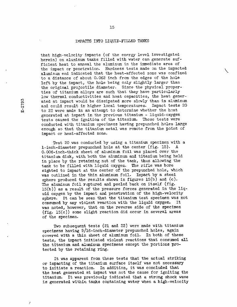
that high-velocity impacts (of the energy level investigated herein) on aluminum tanks filled with water can generate suf-ficient heat to anneal the aluminum in the immediate area of the impact or penetration. Hardness tests made on the impacted aluminum end indicated that the heat-affected zone was confined to a distance of about 0.062 inch from the edges of the hole left by the impact, the hole being only slightly larger than the original projectile diameter. Since the physical proper-ties of titanium alloys are such that they have particularly low thermal conductivities and heat capacities, the heat gener-ated at impact would be dissipated more slowly than in aluminum and could result in higher local temperatures. Impact tests 20 to 22 were made in an attempt to determine whether the heat generated at impact in the previous titanium - liquid-oxygen tests caused the ignition of the titanium. These tests were conducted with titanium specimens having prepunched holes large enough so that the titanium metal was remote from the point of impact or heat-affected zone.
Test 20 was conducted by using a titanium specimen with a 1-inch-diameter prepunched hole at the center (fig. 15). A 0.006-inch-thick sheet of aluminum foil was placed over the titanium disk, with both the aluminum and titanium being held in place by the retaining nut of the tank, thus allowing the tank to be filled with liquid oxygen. The rifle was bore sighted to impact at the center of the prepunched hole, which was outlined in the thin aluminum foil. Impact by a steel sphere produced the results shown in figures 15(b) and (c). The aluminum foil ruptured and peeled back on itself (fig. 15(b)) as a result of the pressure forces generated in the liq-uid oxygen by the impact and penetration of the high-velocity sphere. It can be seen that the titanium test specimen was not consumed by any violent reaction with the liquid oxygen. It was noted, however, that on the reverse side of the specimen (fig. 15(c)) some slight reaction did occur in several areas of the specimen.
Two subsequent tests (21 and 22) were made with titanium specimens having 9/16-inch-diameter prepunched holes, again covered with a thin sheet of aluminum foil. In both of these tests, the impact initiated violent reactions that consumed all the titanium and aluminum specimens except the portions pro-tected by the retaining ring.
It was apparent from these tests that the actual striking or impacting of the titanium surface itself was not necessary to initiate a reaction. In addition, it was concluded that the heat generated at impact was not the cause for igniting the titanium. It was previously indicated that a strong shock wave Is generated within tanks containing water when a high-velocity

particle pierces the tank wall and travels into the water. It was further pointed out that the pressures generated as a re-sult of the shock wave are extremely high (in excess of 100,000 psi for these typical impacts in the immediate area of the im-pact or penetration) hut decay rapidly with distance as the shock wave propagates away from the point of impact. Inasmuch as the energies of impacts into water-filled and liquid-oxygen-filled tanks were of the same order, the pressures generated can reasonably be assumed to have been of similar magnitude, even though the liquid impacted was oxygen rather than water. The liquid pressures exerted on the titanium disks with the smaller holes (9/16-in. diam.) would certainly have been great-er than those sustained by the disk with the larger hole (1-in. diam.). Since no sustained reaction took place in the test of the titanium disk with a 1-inch hole and whereas violent reac-tions did result when titanium disks with 9/16-inch holes were used, it would appear that the pressures acting on the tank wall as a result of the shock wave created in the liquid and/or the resulting high-velocity flow of oxygen over the titanium surfaces may be primary factors in the initiation of these violent titanium - liquid-oxygen reactions.
Impacting projectile size: The titanium - liquid-oxygen impact test 23 was made in order to determine whether or not an impact by a smaller particle could affect a violent reac-tion. A 1/16-inch-diameter steel sphere was used for the im-pact and was accelerated to a velocity of about 5200 feet per second, which resulted in a kinetic energy of about 15 foot-pounds at impact. A violent reaction occurred as a result of this impact. The most obvious conclusion to be drawn from this test is that impacting particle size, at least for spheres as small as 1/16 inch in diameter, is not a factor in the ini-tiating of the titanium - liquid-oxygen reaction.
Visual recordings of impacts: As an aid to further the study of the titanium - liquid-oxygen reaction, high-speed mo-tion pictures (with framing rates up to 6000 frames per sec) were taken of particle impacts and ensuing reactions. These motion pictures do not indicate the source or the cause of the reaction between titanium and liquid oxygen, but they do show that the reaction produced is by no means in a steady-state condition. The quasi-steady-state burning of the titanium is interrupted periodically by a number of flare-ups, explosions, or sudden releases of energy. As many as five violent flare-ups were detected in one sequence. These motion pictures also reveal that, once the reaction is started, it becomes highly exothermic and provides ample heat for sustaining the reaction until either the test specimen is consumed or the supply of oxygen is exhausted.
Oxidation of metals in the presence of liquid oxygen is not normally a problem, because oxygen is relatively inert in the liquid state. In addition, titanium, under normal condi-tions or usage, resists oxidation very well. This oxidation resistance is largely attributed to the formation of a protec-tive oxide at the surface that inhibits further oxidation. Jackson, et al.,4 however, point out that the oxides produced by a titanium - liquid-oxygen reaction are highly soluble in molten titanium and would diffuse rapidly at the reacting sur-face and thereby allow fresh titanium to be exposed for further reaction. It seems quite reasonable then that, once a reaction has been initiated, it can proceed or propagate with little or no retardation from the oxides formed.
Comparison with other investigations: The results of tests conducted by other investigators12,13,14 indicate that titanium-oxygen reactions can be initiated by the piercing, puncturing, or penetration of a titanium wall of a pressurized tank filled with either gaseous or liquid oxygen. The testing methods involved both the drop-weight type of apparatus with a falling sharp tool and an explosive-charge technique for accel-erating small, steel, disk-shaped projectiles to high veloci-ties for impacting and penetrating the tanks. The tests con-ducted with the explosive-charge technique, however, often re-sulted in a splattering- or fragmenting-type impact. Neverthe-less, the types of reactions produced by these tests were gen-erally very similar to those reported herein. The propagation of the titanium-oxygen reaction, however, was not nearly as complete or extensive as for the impact tests of this investi-gation. A possible explanation may be that the supply of oxy-gen was exhausted and therefore insufficient to support further oxidation.
From the drop-weight puncture tests,12,13 it was concluded that the rate of incidence of severe burning reactions in-creases directly with increased initial pressurization of the oxygen, but a minimum pressure threshold below which a reaction did not initiate was not found.
In the investigation reported herein and in other inves-tigations,12,13,14 no reactions took place when small, high-velocity projectiles impacted but did not penetrate the ti-tanium wall in contact with oxygen. There also does not appear to be a significant difference in the reactions produced by im-pact of either of the two titanium alloys investigated (5A1-2.5 Sn-Ti and 6A1-4V-Ti).
Methods investigated,12,13 to retard or inhibit the reac-tions by coating the titanium specimens with aluminum foil,

aluminum dipping, vapor-deposited aluminum, or electrodeposited copper, nickel, gold, or silver were generally ineffective.
Reinforced Plastics. - An increased interest has been gen-erated in utilizing reinforced plastics as propellant tanks for space or missile applications because of their high strength-to-weight ratio compared with some of the commonly used metals. Standard drop-impact tests,3,4,6 however, indi-cated that plastics, in general, exhibit impact sensitivity when submerged in liquid oxygen. Three types of reinforced plastics were used for the impact tests of simulated tanks filled with liquid oxygen: nylon-cloth-reinforced phenolic resin, Dacron-fiber-reinforced polyurethane, and glass-cloth-reinforced epoxy resin. On a weight basis, these filament-reinforced plastic materials were about 80 percent filament material and 20 percent polymeric binding material.
All impacts on reinforced-plastic walls were made with 7/32-inch-diameter steel spheres having velocities between 6230 and 6330 feet per second, which resulted in kinetic energies between 929 and 959 foot-pounds.
Impacts made on two simulated glass-cloth-reinforced epoxy-resin tank walls in contact with liquid oxygen resulted in penetrations of the specimens with no sustained burning or chemical reaction. The plastic or glass cloth fibers at the edges of the penetration had a dark appearance, which indicated that singeing may have taken place. In the area surrounding the hole left by the impact, a stress pattern was noted. Other evidence of high stress appears toward the outer edges of the disk, that is, where the specimen was secured by the retaining nut.
Impacts on both the nylon-cloth-reinforced phenolic-resin specimen and the Dacron-fiber-reinforced polyurethane specimen resulted in catastrophic fracturing of the impacted wall. The failure of the phenolic tank wall was representative of a brit-tle fracture, whereas the failure of the polyurethane tank wall was more typical of a rupture of a flexible material. Neither impact resulted in any burning or chemical reaction; however, it was noted that a darkened appearance existed around the edges of the impact point of the polyurethane specimen, similar to that from the impacts on the glass-cloth - epoxy-resin spec-imens.
All specimens were impacted at projectile energy levels above 900 foot-pounds, and no chemical reaction resulted. Jackson, et al., reports that plastics, similar to those used

as the binder in the reinforced-plastic materials investigated herein, were impact sensitive to liquid oxygen under drop-test conditions at energy levels of only 80 foot-pounds. It might be expected that the glass-reinforced material investigated (consisting of only 20 percent organic plastic material) might be less impact sensitive in a liquid-oxygen environment than the other materials in which the reinforcing fibers as well as the binder were organic materials. For the energy levels in-vestigated herein, no conclusions relative to this possibility could be made, but it is of interest to note that small, high-velocity projectile penetrations into materials that were 100-percent polymeric did not cause reactions with liquid oxygen even though the kinetic-energy levels were much higher than those employed in other tests.3,4,6 It would seem that, based on the results of others,3,4,6 the results obtained herein, the impact mode plus the size, velocity, and/or shape of the impacting projectile may affect the reactivity of polymeric ma-terials in the presence of liquid oxygen.
Aluminum (6061-T3). - Two impacts (tests 28 and 29) were made on a 0.031-inch-thick aluminum tank wall using 7/32-inch steel spheres. The projectile impact velocity and resulting impact energy for both these tests were 5800 feet per second and 805 foot-pounds. Impact and penetration of the tank walls produced pronounced bulging of the impacted wall but revealed no indications of chemical interaction.
Stainless Steel (AISI 304). - The test conditions (pro-jectile size, material, and velocity along with tank-wall thickness) for the impact on the stainless-steel tank wall (test 30) were similar to those of the impacts on the aluminum tanks. The results of the impact and penetration of the pro-jectile were also similar; that is, the impact produced bulging of the tank wall with no signs of chemical interaction.
Nitrogen Tetroxide
Because of the high content of oxygen (70 percent by weight) in the propellant, nitrogen tetroxide, impacts were conducted on titanium specimens in contact with this propellant to determine whether reactions similar to the titanium -liquid-oxygen reaction would occur.
Several impact tests were conducted on simulated titanium tanks filled with nitrogen tetroxide by using both a high-speed

rifle (tests 31 and 32) and a light-gas gun (tests 33 to 37, conducted at the Utah Research and Development Company). The impacting projectiles for these tests were 1/16-, 3/16-, and 7/32-inch spheres of steel and 1/8- and 7/32-inch spheres of aluminum. Two alloys of titanium (5A1-2.5Sn-Ti and 6A1-4V-Ti) were used for the tank-wall specimens, which varied from 0.020 to 0.062 inch in thickness. Projectile impact velocities ranged from 5800 to 20,400 feet per second, and projectile im-pact energies ranged from 53.6 to 3153 foot-pounds.
Impact of a 0.031-inch-thick wall specimen (test 36) by a 1/8-inch aluminum sphere at a velocity of 20,400 feet per sec-
ond resulted in a rather violent catastrophic-type rupturing of the tank wall (see fig. 16(a)). In addition to this cata-strophic fracturing of the specimen, a possible chemical reac-tion was detected (see fig. 16(b)). The reaction, however, was not sustained, and only the surface of the titanium specimen in a region near the hole or penetration made by the impacting projectile was affected. Only one other impact (test 37) re-sulted in any sign of chemical reactivity and this again was in the nature of a surface-type reaction near the hole produced by the impacting projectile.
Hydrazine
The tank materials investigated with the propellant, hy-drazine, were aluminum and stainless steel (tests 38 and 39). In both tests a 7/32-inch steel sphere was accelerated to a velocity of 5800 feet per second, resulting in a kinetic energy at impact of 805 foot-pounds. On inspection of the tanks after impact, there was no evidence to indicate that a chemical in-teraction of the tank wall and contained propellant had taken place, nor did the high-speed motion pictures reveal any evi-dence of combustion or burning other than the initial flash produced at the time of impact. The impacted tank ends, how-ever, did show pronounced bulging and detachment of the ends from the tank resulting from the extreme pressure forces gener-ated against the tank walls.
Unsymmetrical Dimethylhydrazine
Impact of a simulated titanium tank filled with the pro-pellant, UDMH, (test 40) was made with a 7/32-inch spherical steel projectile at a velocity of 5800 feet per second. The results of this test were very similar to those of the tests with hydrazine; that is, the impact and penetration of the tank
wall produced some bulging of the wall, but there was no evi-dence of a chemical interaction occurring.
CONCLUSIONS
The following conclusions can be drawn from the prelim-inary investigation of the effects of impact by small, high-velocity projectiles into liquid-filled tanks:
1. Catastrophic fracturing of tank walls rather than sim-ple puncturing can result when impact velocity exceeds a given critical value which is dependent on the projectile size, den-sity and/or material; tank-wall material and thickness; the initial static stress level in the tank wall before impact; and the liquid contained in the tank.
2. Catastrophic fracturing of pressurized gas-filled tanks did not occur when impacted by projectiles of high velocity; however, fractures did occur at low impact velocities because of the tearing of the wall caused by the penetrating projec-tile.
3. The critical impact velocities or energies required to fracture the wall of a liquid-filled tank are considerably greater than those required only to puncture the wall.
4. For a given size projectile, the critical velocity in-creased and the kinetic energy decreased as the projectile density decreased.
5. Tank walls of AISI 301 stainless steel were more resis-tant to fracture than the aluminum alloys.
6. The pressure pulses generated in the water-filled tank by the impacting projectiles are large but decay rapidly, approaching ambient pressures within about 5 inches from the point of impact. Pressures of about 120,000 psi were recorded 0.6 inch from the impact point for impacts by 7/32-inch spher-ical projectiles with velocities about 7500 feet per second.
7. The shock front generated in the water-filled tank traveled only a few inches from the point of impact before fracture of the tank wall occurred. Fractures of the tank wall occurred between 27 to 40 microseconds after impact. For the thicknesses and materials investigated, the pressure pulse generated in water due to impact and the resulting forces con-tributing to the initial fracturing of the tank walls are local phenomena and are independent on tank size greater than a few inch radius.
8. Impact and penetration of titanium tank walls in con-tact with liquid oxygen resulted in a violent explosive and/or pyrophoric reaction. No reactions were obtained when the wall was impacted but not penetrated. Projectile impacts directed through a hole of a prepunched titanium wall (covered by a thin aluminum foil to contain the oxygen) also resulted in a reac-tion between the titanium and liquid oxygen.
9. No chemical reactions resulted from impacts of tanks of aluminum, stainless steel, and reinforced plastics contain-ing the propellant, liquid oxygen.
10. Impacts conducted on titanium tank walls in contact with nitrogen tetroxide resulted in no sustained chemical in-teraction of the tank-wall material and the contained propel-lant; however, a very limited, but noticeable, surface reaction occurred on two of the impacted tank walls.
11. No chemical reactions occurred as a result of impacts on aluminum or stainless-steel wall materials in contact with the propellant, hydrazine.
12. No chemical reaction occurred from the impact and penetration of a simulated titanium tank filled with unsym-metrical dimethylhydrazine.
REFERENCES
1. Herrmann, Walter, and Jones, Arfon H.: Survey of Hyper-velocity Impact Information. ASRL-99-1, M.I.T., Oct. 1961.
2. Anon.: Proceedings of the Fifth Symposium on Hypervelocity Impact, Oct. 30 - Nov. 1, 1961, vol. 1, pts. 1-2, Colo-rado School of Mines, Apr. 1962.
3. Key, C. F., and Riehl, W. A.: Compatibility of Materials with Liquid Oxygen. NASA MTP-P&VE-M-63-14, 1963.
4. Jackson, J. D., Miller, P. D., Boyd, W. K., and Fink, F. W.: A Study of Titanium-Liquid Oxygen Pyrophoric Reaction. TR 60-258, WADD, June 1960.
5. Sterner, C. J., and Singleton, Alan H.: The Compatibility of Various Metals with Liquid Fluorine. TR 60-819, WADD, Mar. 1961.
6. Hauser, R. L., Sykes, G. E., and Rumpel, W. F.: Mechani-cally Initiated Reactions of Organic Materials in Mis-sile Oxidizers. TR 61-324, Aeronautical Systems Div., Oct. 1961.
7. Scott, H. F., Jr., Alley, C. W., and Hayford, A. W.: Im-pact Sensitivity of Metals (Titanium) Exposed to Liquid Nitrogen Tetroxide. Allied Chem., Corp., Nov. 4, 1960.
8. Stepka, Francis S., and Morse, C. Robert: Preliminary In-vestigation of Catastrophic Fracture of Liquid-Filled Tanks Impacted by High-Velocity Particles. NASA TN D-1537, 1963.
9. Dengler, Robert P.: An Experimental Investigation of Chemical Reaction Between Propellant Tank Material and Rocket Fuels or Oxidizers When Impacted by Small High-Velocity Projectiles. NASA TN D-1882, 1963.
10. Cole, Robert H.: Underwater Explosions. Princeton Univ. Press, 1948, pp. 36-47.
11. Malik, D.: Empirical Study of Residual Velocity Data for Steel Fragments Impacting on Four Materials. Proc. Third Symposium on Hypervelocity Impact. Vol. 2, Armour Res. Foundation, Chicago, Ill., Oct. 7-9, 1958.
12. Riehl, W. A., Key, C. F., and Gayle, J. B.: Reactivity of Titanium with Oxygen. NASA TR R-180, 1963.

13. Chafey, J. E., Witzell, W. E., and Scheck, W. G.: Titanium-Oxygen Reactivity Study. AE62-0674, General Dynamics/Astronautics, July 2, 1962.
14. Rolsten, R. F., Hunt, H. H., and Wellnitz, J. N.: Hyper-velocity Impact on Pressurized Structures (Part 1), AE62-0207, General Dynamics/Astronautics, Jan. 1962.
Specimen Tank Projectile Material Thickness,
t, in.
Ratio of initial static stress to yield strength
Liquid Volume, cu ft
Diameter, in.
Material Density, lb/cu in.
Weight, lb
Minimum conditions for fracture
Maximum impact con-ditions (no frac-tures obtainable)
Velocity, ft/sec
Kinetic energy, ft-lb
Velocity, ft/sec
Kinetic energy, ft-lb
Aluminum 7075-T6
1/32 1.0 Water 0.6 7/32 Nylon 0.042 2.31x10⁻⁴ a1650 a9.8 Aluminum .101 5.53 5000 215 Steel .281 15.41 3300 260 Tungsten .540 29.64 2850 375
1/8 Steel 0.281 2.87x10⁻⁴ 7180 230 1/8 Tungsten .540 5.50 7120 432 3/32 Aluminum .101 .428 6580 28.7 1/16 Steel .281 .357 7050 27.5
1/16 1.0 Water 0.6 7/32 Nylon 0.042 2.31x10⁻⁴ 6800 165 Aluminum .101 5.53 5700 280 Steel .281 15.41 6000 860 Tungsten .540 29.64 3000 414
1/32 0 Water 0.6 7/32 Nylon 0.042 2.31x10⁻⁴ 6300 140 Aluminum .101 5.53 6200 330 Steel .281 15.41 6100 890 Tungsten .540 29.64 5000 1150
bo Water 0.6 7/32 Nylon 0.042 2.31x10⁻⁴ 6300 140 Aluminum .101 5.53 4950 210 Steel .281 15.41 4900 575 Tungsten .540 29.64 3700 630
0 Glycerin 0.6 7/32 Nylon 0.042 2.31x10⁻⁴ 6900 170 Aluminum .101 5.53 5900 300 Steel .281 15.41 5900 830
1.0 Nitrogen 0.6 7/32 Aluminum 0.101 5.53x10⁻⁴ 5100 223 0 Nitrogen .6 7/32 Aluminum .101 5.53 6900 385
1.0 Water 15.1 7/32 Nylon 0.042 2.31x10⁻⁴ a4000 a57 Aluminum .101 5.53 5500 259 Steel .281 15.41 3700 325
Aluminum 2014-T6
1/32 1.0 Water 0.6 7/32 Nylon 0.042 2.31x10⁻⁴ 7000 175 Aluminum .101 5.53 4700 190 Steel .281 15.41 4800 550 Tungsten .540 29.64 2900 385
1/16 1.0 Water 0.6 7/32 Nylon 0.042 2.31x10⁻⁴ 6500 152 Aluminum .101 5.53 5 700 280 Steel .281 15.41 5800 805 Tungsten .540 29.64 4300 850
1/32 1.0 Water 15.1 7/32 Nylon 0.042 2.31x10⁻⁴ 6000 130 Aluminum .101 5.53 4800 198 Steel .281 15.41 3600 310
Stainless steel AISI 301
1/32 0 Water 0.6 7/32 0.101 5.53x10⁻⁴ 6500 363 Tungsten .540 29.64 5000 1150 Copper (cylinder)
.321 63.43 4900 2365
1.0 Water 0.6 7/32 Copper (cylinder)
0.321 63.43x10⁻⁴ 3900 1500
Nylon .042 2.31 6800 165 Steel .281 15.41 5000 600
TABLE I. - MAXIMUM IMPACT CONDITIONS AND MINIMUM CONDITIONS FOR FRACTURING OP LIQUID-PILLED TANKS
aNot minimum, test terminated at this condition. bWall prepunched and hole covered with masking tape.
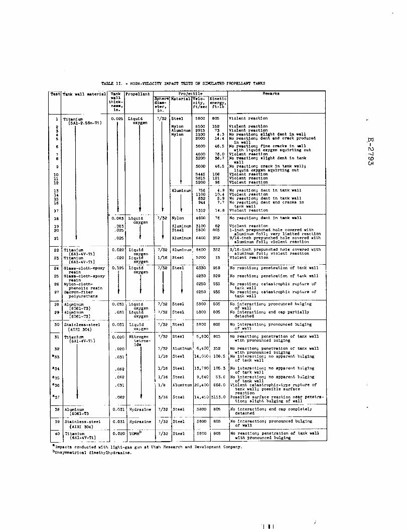
Test Tank wall material Tank wall thick-ness, in.
Propellant Projectile Remarks
TABLE II. - HIGH-VELOCITY IMPACT TESTS ON SIMULATED PROPELLANT TANKS
Spherediam-eter, in.
Material Velo-city, ft/sec
Kinetic energy, ft-lb
1 Titanium (5A1-2.5Sn-Ti)
0.025 Liquid oxygen
7/32 Steel 5800 805 Violent reaction
2 Nylon 6500 152 Violent reaction Aluminum 2915 73 Violent reaction 3
4 Nylon 1100 4.3 No reaction; slight dent in wall 2000 5 14.4 No reaction; dent and crack produced
in wall 6 3600 46.5 No reaction; fine cracks in wall
with liquid oxygen squirting out 7 4600 76.0 Violent reaction 8 3200 36.7 No reaction; slight dent in tank
wall 9 3600 46.5 No reaction; crack in tank wall;
liquid oxygen squirting out 10 5445 106 Violent reaction 11 5815 121 Violent reaction 12 5200 96 Violent reaction
13 Aluminum 756 4.9 No reaction; dent in tank wall 14 1100 10.4 Violent reaction 15 832 5.9 No reaction; dent in tank wall 16 944 7.7 No reaction; dent and cracks in
tank wall 17 1312 14.8 Violent reaction
18 0.063 Liquid oxygen
7/32 Nylon 4600 76 No reaction; dent in tank wall
19 .063 Aluminum 3100 82 Violent reaction 20 .025 Steel 5800 805 1-inch prepunched hole covered with
aluminum foil; very limited reaction 21 .025 Aluminum 6400 352 9/16-inch prepunched hole covered with
aluminum foil; violent reaction
22 Titanium (6A1-4V-Ti)
0.020 Liquid oxygen
7/32 Aluminum 6400 352 9/16-inch prepunched hole covered with aluminum foil; violent reaction
23 Titanium (6A1-4V-Ti)
.020 Liquid oxygen
1/16 Steel 5200 15 Violent reaction
24 Glass-cloth-epoxy resin
Glass-cloth-epoxy resin
0.125 Liquid oxygen
7/32 Steel 6330 959 No reaction; penetration of tank wall
25 6230 929 No reaction; penetration of tank wall
26 Nylon-cloth-phenolic resin
6250 935 No reaction; catastrophic rupture of tank wall
27 Dacron-fiber polyurethane
6250 935 No reaction; catastrophic rupture of tank wall
28 Aluminum (6061-T3)
0.031 Liquid oxygen
7/32 Steel 5800 805 No interaction; pronounced bulging of wall
29 Aluminum (6061-T3)
.031 Liquid oxygen
7/32 Steel 5800 805 No interaction; end cap partially detached
30 Stainless-steel (AISI 304)
0.031 Liquid oxygen
7/32 Steel 5800 805 No interaction; pronounced bulging of wall
31 Titanium (6A1-4V-Ti)
0.020 Nitrogen tetrox-ide
7/32 Steel 5,800 805 No reaction; penetration of tank wall with pronounced bulging
32 .020 7/32 Aluminum 6,400 352 No reaction; penetration of tank wall with pronounced bulging
No interaction; no apparent bulging of tank wall
a33 .031 1/16 Steel 14,000 108.5
a34 .062 1/16 Steel 13,790 105. 3 No interaction; no apparent bulging of tank wall
a35 .062 1/16 Steel 9,840 53.6 No interaction; no apparent bulging of tank wall
a36 .031 1/8 Aluminum 20,400 666.0 Violent catastrophic-type rupture of tank wall; possible surface reaction a37 .062 3/16 Steel 14,450 3153.0 Possible surface reaction near penetra-tion; alight bulging of wall
38 Aluminum (6061-T3
0.031 Hydrazine 7/32 Steel 5800 805 No interaction; end cap completely detached
39 Stainless-steel (AISI 304)
0.031 Hydrazine 7/32 Steel 5800 805 No interaction; pronounced bulging of wall
40 Titanium (6A1-4V-Ti)
0 . 0 2 0 UDMHb 7/32 Steel 5800 805 No reaction; penetration of tank wall with pronounced bulging
aImpacts conducted with light-gas gun at Utah Research and Development Company. bUnsymmetrical dimethylhydrazine.

Figure 1. - Schematic drawing of apparatus for impact into l iquid- f i l led tank by h igh-ve loc i ty projecti le.
Figure 2. - NASA Lewis Research Center l ight -gas g u n facil i ty.
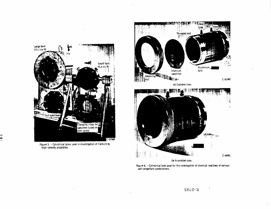
Figure 3. - Cyl indr ical tanks used in investigation of f rac tu re by h igh-ve loc i ty projecti les.
F igure 4 . - Cyl indr ical tank used for the investigation of chemical reactions of various wal l -propel lant combinations.

DYNAMIC STRESSES IN TANK WALL DUE TO IMPACT AND PENETRATION
FUNCTION OF:
1. PROJECTILE VELOCITY 2. PROJECTILE MATERIAL
AND/OR DENSITY 3. PROJECTILE SIZE 4. PROJECTILE SHAPE
+STRESSES IN WALL
DUE TO LIQUID PRESSURE
FUNCTION OF:
1. LIQUID STATIC PRESSURE
2. LIQUID DENSITY 3. LIQUID VELOCITY
OF SOUND 4. LIQUID TEMPERATURE 5. PROJECTILE VELOCITY 6. PROJECTILE MATERIAL
AND/OR DENSITY 7. PROJECTILE SIZE 8. PROJECTILE SHAPE
STRESS FOR CATASTROPHIC BRITTLE FRACTURE
FUNCTION OF:
1. SHAPE AND SIZE OF HOLE AND/OR M I C R O -CRACKS FROM IMPACT
2. MATERIAL-STRENGTH PROPERTIES AT HIGH RATE OF LOADING
3. MATERIAL-STRENGTH PROPERTIES AT TEM-PERATURE OF LIQUID
Figure 5. - Factors affecting catastrophic f rac ture of l iqu id - f i l l ed tanks of given thickness and material impacted by high-veloci ty projecti les.
(b) Impacts above cr i t ical velocity: f r ac tu re .
Figure 6. - Results of impacts by 7 /32- inch spheres in to prestressed specimens of 7075-T6 a l u m i n u m on water - f i l led tank .
(a) Impact below cr i t ical velocity: p u n c t u r e .
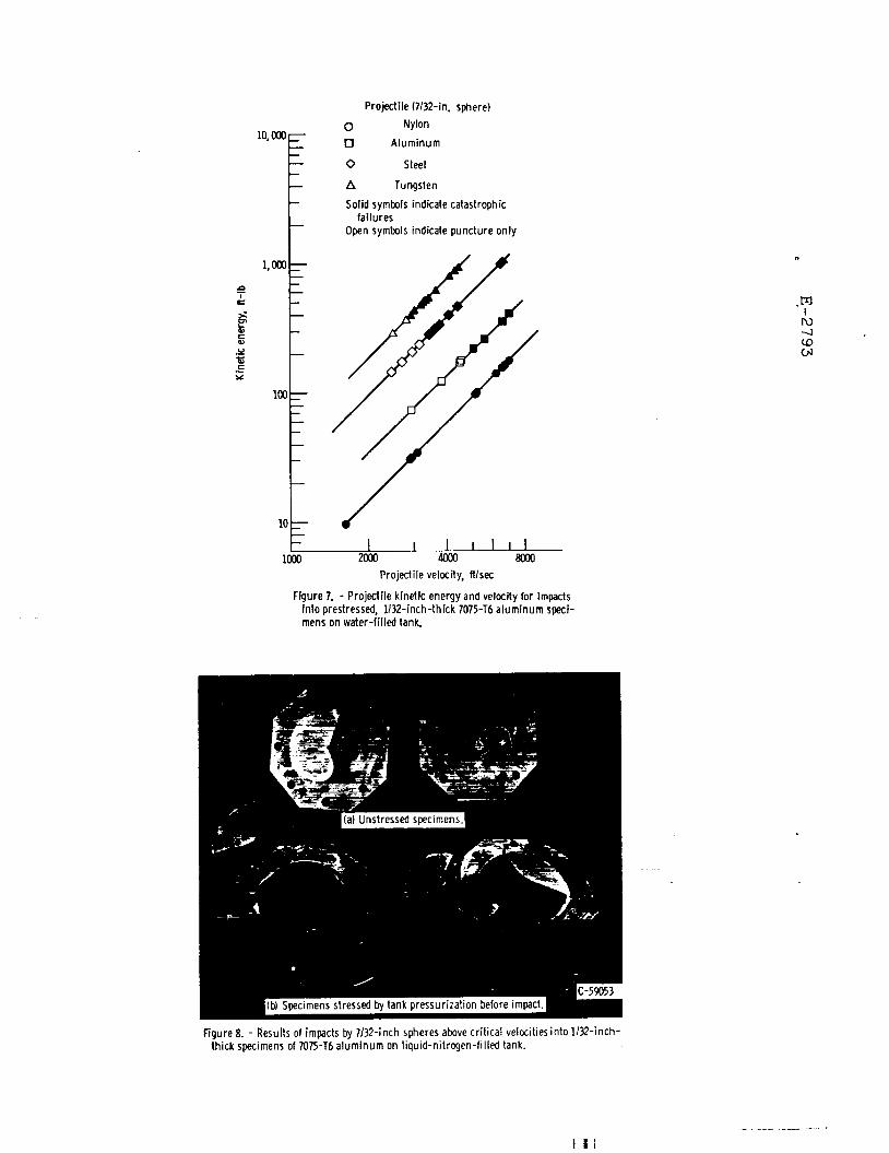
Figure 7. - Project i le kinetic energy and velocity (or impacts into prestressed, 1 / 3 2 - i n c h - t h i c k 7075-T6 a l u m i n u m speci-mens on water - f i l l ed tank .
Figure 8. - Results of impacts by 7 /32 - inch spheres above cr i t ical velocities into 1 / 3 2 - i n c h -thick specimens of 7075-T6 a l u m i n u m on l iqu id -n i t rogen- f i l l ed tank.

Figure 9. - Propagation of shock produced by h igh-ve loc i ty projecti le impacting into a water - f i l led t ransparent plastic tank. ( Impacting projecti le: 7 / 3 2 - i n c h a l u m i n u m sphere at velocity of approx-imately 6690 ft/sec.)
F igure 10. - Effect of h igh-speed projecti le impact into prestressed specimen of 1 /32 - inch thick 7075-T6 a l u m i n u m on water - f i l l ed tank . ( Impacting particle is 7 /32- inch a l u m i n u m sphere at velocity of 5780 ft/sec.)
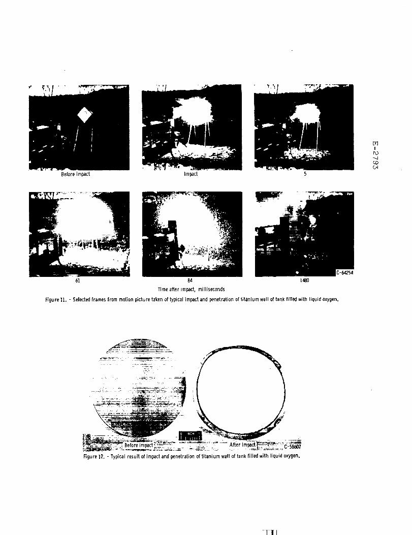
Figure 11. - Selected frames from motion picture taken of typical impact and penetrat ion of t i tan ium wall of tank f i l led with l iquid oxygen.
Figure 12. - Typical result of impact and penetration of t i t a n i u m wal l of tank fi l led with l iquid oxygen.

Figure 13. - Condit ion of l iquid-oxygen-f i l led test tank after impact and penetrat ion of t i t a n i u m wall specimen.
(b) Surface in contact wi th l iquid oxygen. Figure 14. - Results of impacts wi thout complete penetration of t i t a n i u m
wall of tank fi l led with l iquid oxygen.
(a) Impacted surface.

(a) Schematic of test tank. (b) Front side of t i t an ium disk after impact.
(c) Reverse side of t i t an ium disk after impact.
Figure 15. - impact test on prepunched t i tan ium specimen covered with a l u m i n u m foil (test 20).
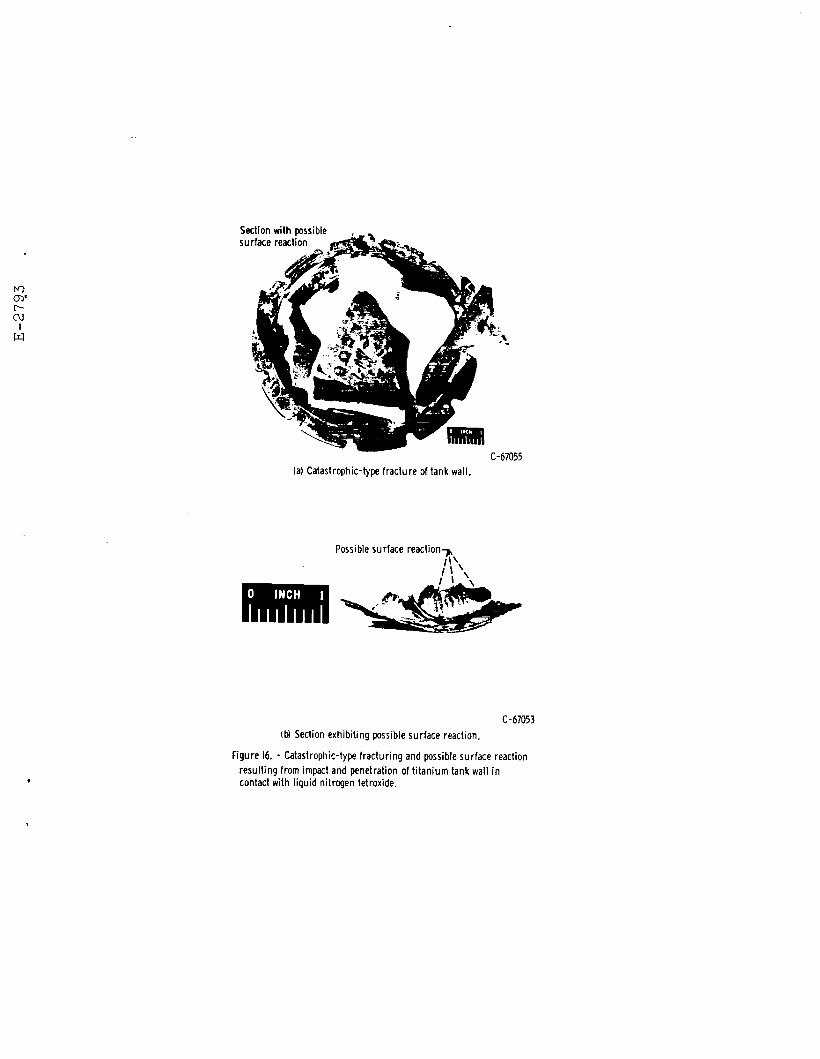
(b) Section exhibi t ing possible sur face reaction.
Figure 16. - Catastrophic-type f rac tur ing and possible surface reaction resul t ing from impact and penetrat ion of t i t a n i u m tank wail in contact with liquid nitrogen tetroxide.
(a) Catastrophic-type f rac tu re of tank wal l .