Investigation of aluminium plate damage visualization by ... · Investigation of aluminium plate...
10
Investigation of aluminium plate damage visualization by through-the-thickness ultrasound generated and detected by lasers A. D. Abetew, S. C. Hong & J. R. Lee Department of Aerospace Engineering, Korea Advanced Institute of Science and Technology, Republic of Korea Abstract In this study, the full-field pulse-echo ultrasonic wave propagation imaging (FF- PE-UWPI) technique is proposed for three-dimensional damage evaluation. To realize this objective, a full-field pulse-echo ultrasonic propagation imaging (FF- PE-UPI) system has been developed using Q-switched Nd: YAG laser to generate diverse mode ultrasounds by thermoelastic mechanism at the impinging point of generation laser beam, laser Doppler vibrometry (LDV) sensor for sensing ultrasound and two axis transition stage for raster scan of two laser beams, so that the FF-PE-UPI system allows scanning of both ultrasonic excitation and sensing laser beams simultaneously, this generation and sensing principle is repeated over the scan area. Contrary to the conventional ultrasonic propagation imaging which has imaged in-plane guided wave propagated from a single ultrasonic source or multiple source, the proposed system makes full-field ultrasound as large as the scanned area and visualizes longitudinal wave propagation through the thickness. Thus, the system allows us to evaluate the damage three dimensionally with more accurate sizing and shaping. To verify the effectiveness of the system, an aluminium plate of 4 mm with a 2 mm thickness at the milled area was tested. From the imaging results obtained from the FF-PE-UWPI technique, the damage on the tested specimen was successfully detected, localized and clearly visualized. Keywords: full-field pulse-echo ultrasonic wave propagation imaging technique, through-the-thickness ultrasound, three-dimensional evaluation, wall-thinning aluminium plate. This paper is part of the Proceedings of the 14 International Conference th on Structures Under Shock and Impact (SUSI 2016) www.witconferences.com doi:10.2495/SUSI16041 www.witpress.com, ISSN 1743-3509 (on-line) WIT Transactions on The Built Environment, Vol 160, © 2016 WIT Press
Transcript of Investigation of aluminium plate damage visualization by ... · Investigation of aluminium plate...

Investigation of aluminium plate damage visualization by through-the-thickness ultrasound generated and detected by lasers
A. D. Abetew, S. C. Hong & J. R. Lee Department of Aerospace Engineering, Korea Advanced Institute of Science and Technology, Republic of Korea
Abstract
In this study, the full-field pulse-echo ultrasonic wave propagation imaging (FF-PE-UWPI) technique is proposed for three-dimensional damage evaluation. To realize this objective, a full-field pulse-echo ultrasonic propagation imaging (FF-PE-UPI) system has been developed using Q-switched Nd: YAG laser to generate diverse mode ultrasounds by thermoelastic mechanism at the impinging point of generation laser beam, laser Doppler vibrometry (LDV) sensor for sensing ultrasound and two axis transition stage for raster scan of two laser beams, so that the FF-PE-UPI system allows scanning of both ultrasonic excitation and sensing laser beams simultaneously, this generation and sensing principle is repeated over the scan area. Contrary to the conventional ultrasonic propagation imaging which has imaged in-plane guided wave propagated from a single ultrasonic source or multiple source, the proposed system makes full-field ultrasound as large as the scanned area and visualizes longitudinal wave propagation through the thickness. Thus, the system allows us to evaluate the damage three dimensionally with more accurate sizing and shaping. To verify the effectiveness of the system, an aluminium plate of 4 mm with a 2 mm thickness at the milled area was tested. From the imaging results obtained from the FF-PE-UWPI technique, the damage on the tested specimen was successfully detected, localized and clearly visualized. Keywords: full-field pulse-echo ultrasonic wave propagation imaging technique, through-the-thickness ultrasound, three-dimensional evaluation, wall-thinning aluminium plate.
This paper is part of the Proceedings of the 14 International Conference th
on Structures Under Shock and Impact (SUSI 2016) www.witconferences.com
doi:10.2495/SUSI16041
www.witpress.com, ISSN 1743-3509 (on-line) WIT Transactions on The Built Environment, Vol 160, © 2016 WIT Press

1 Introduction
The use of composites in aircraft manufacturing is growing dramatically. Almost the entire fuselage of the Boeing 787 is made of composite, the Airbus A380 and A350 also incorporate significant composite structures. Regional and business jet manufacturers also increased their use of composite. The same growth is being observed in military aircraft (Marsh [1]), [2]. Usually, aircraft structures are subjected to impacts and lightning strikes. Impacts on aircraft structures can cause different types of damage to composite structures, the principals are delamination and disbonds. This significantly hurt the integrity of the structures. Therefore, reliable and efficient Non-destructive Testing (NDT) methods are needed to quickly assess possible damage. As a result, NDT methods have been developed to assess bonding quality during maintenance and in-service inspection requirements. The importance of NDT methods for impact problems also showed by other studies [3, 4, 9–11]. In addition, owing to aging of infrastructures, it is important to monitor structural health and ensure the system’s integrity by identifying the initiation of damage before it reaches critical stage (Cheng et al. [5]). Nowadays there have been increasing demands for structural health monitoring (SHM) techniques to better safeguard civil, mechanical and aerospace engineering structures (Lee et al. [6]). The onsite time effective inspection system for residual lifetime assessment of infrastructure needs further improvement. To have precise residual lifetime assessment, optical inspection using laser is one of the most useful options structural health monitoring system (Yamashita [7]). The formation of imaging techniques for evaluating this damage provides direct or indirect, immediate and quantitative results. Each individual technique has its own and specific applications, advantages, as well as limitations, due to the nature of imaging algorithm (Cheng et al. [5]). The laser beam in the pulsed mode can provide many advantages including fast wave generation with low pulse energy, high spatial resolution, inspection ability on complex target and so on (Lee et al. [9]). In this study, a non-contact full-field laser pulse-echo ultrasonic propagation imaging (FF-PE-UPI) system is realized for three-dimensional evaluation of artificially introduced damage. Contrary to the conventional ultrasonic propagation imaging (Chia et al. [8], Lee et al. [9]) which has imaged in-plane guided wave propagated from a single ultrasonic source or multiple source, the proposed system makes full-field ultrasound as large as the scanned area and visualizes longitudinal wave propagation through the thickness. The through-the-thickness ultrasonic wave propagation imaging (UWPI) enabled more accurate damage sizing and shaping and provided three dimensional information on the damage. The non-destructive non-contact FF-PE-UPI system has examined a large number of composite and metallic specimens for flaw detection, visualization and evaluation of damage size and shape. Due to legal issues, these results cannot be presented in this paper. Though, at this time we demonstrate the overall capabilities of the system using a sample of aluminium plate.
28 Infrastructure Risk Assessment and Management
www.witpress.com, ISSN 1743-3509 (on-line) WIT Transactions on The Built Environment, Vol 160, © 2016 WIT Press

2 Full-filled pulse-echo ultrasonic propagation imaging system
Conventional methods of non-destructive testing include contact-type transducers which are usually surface mounted or embedded on test structures, because of this, it is tough to apply in harsh environment and in dynamic structures. Ultrasonic immersion testing also a popular conventional non distractive testing technic for investigation of a materials however it is not suitable for inspections where the material absorbs water and contamination or damage would result, due to this there has been increased interest in using air as a coupling medium however much greater attenuation and lower acoustic impedance especially at high frequency leading to difficulties in coupling energy in solid samples (Gan et al. [10]). The FF-PE-UPI system is different from conventional ultrasonic testing system that generates C-scan result (as shown in fig. 1), the system provides a fully non-contact laser excitation and sensing system, enabling inspection on complex target at relatively large stand-off distance, rapid and coupling free damage assessment system. It consists of a Q-switched Nd-YAG laser, laser Doppler vibrometry (LDV), control unit and a vertical and horizontal axis transition stages.
Figure 1: Full-field pulse-echo laser ultrasonic propagation imaging system configuration.
Infrastructure Risk Assessment and Management 29
www.witpress.com, ISSN 1743-3509 (on-line) WIT Transactions on The Built Environment, Vol 160, © 2016 WIT Press
2.1 Working principle
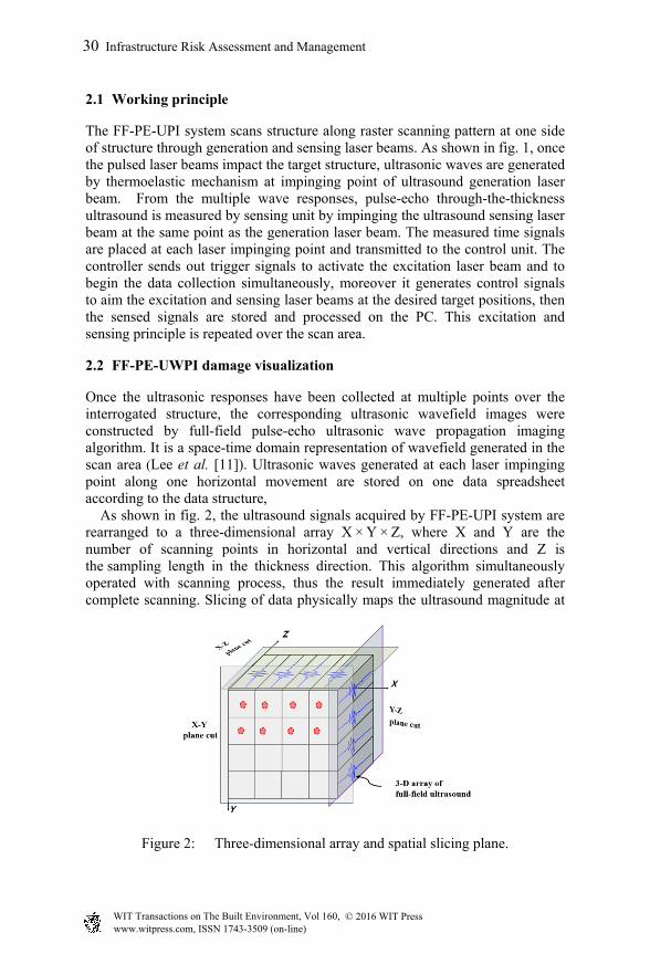
The FF-PE-UPI system scans structure along raster scanning pattern at one side of structure through generation and sensing laser beams. As shown in fig. 1, once the pulsed laser beams impact the target structure, ultrasonic waves are generated by thermoelastic mechanism at impinging point of ultrasound generation laser beam. From the multiple wave responses, pulse-echo through-the-thickness ultrasound is measured by sensing unit by impinging the ultrasound sensing laser beam at the same point as the generation laser beam. The measured time signals are placed at each laser impinging point and transmitted to the control unit. The controller sends out trigger signals to activate the excitation laser beam and to begin the data collection simultaneously, moreover it generates control signals to aim the excitation and sensing laser beams at the desired target positions, then the sensed signals are stored and processed on the PC. This excitation and sensing principle is repeated over the scan area.
2.2 FF-PE-UWPI damage visualization
Once the ultrasonic responses have been collected at multiple points over the interrogated structure, the corresponding ultrasonic wavefield images were constructed by full-field pulse-echo ultrasonic wave propagation imaging algorithm. It is a space-time domain representation of wavefield generated in the scan area (Lee et al. [11]). Ultrasonic waves generated at each laser impinging point along one horizontal movement are stored on one data spreadsheet according to the data structure, As shown in fig. 2, the ultrasound signals acquired by FF-PE-UPI system are rearranged to a three-dimensional array X × Y × Z, where X and Y are the number of scanning points in horizontal and vertical directions and Z is the sampling length in the thickness direction. This algorithm simultaneously operated with scanning process, thus the result immediately generated after complete scanning. Slicing of data physically maps the ultrasound magnitude at
Figure 2: Three-dimensional array and spatial slicing plane.
30 Infrastructure Risk Assessment and Management
www.witpress.com, ISSN 1743-3509 (on-line) WIT Transactions on The Built Environment, Vol 160, © 2016 WIT Press

every laser impinging points of the scanned area. These slices were successively loaded to an intensity graph; as a result, the ultrasound wave propagation video through the scanned area is generated. Every plot of intensity graph also represents one image snapshot from the video (Chia et al. [8], Lee et al. [11]). Finally, it visualizes propagation of a full-field ultrasound along to time domain after signal and image processing in real- time.
3 Experiments
To verify the effectiveness of the proposed non-distractive non-contact full-filled pulse-echo ultrasonic propagation imaging (FF-PE-UPI) system, full-filled pulse-echo ultrasonic wave propagation imaging (UWPI) damage visualization algorithms was carried out using an aluminum plate of 4 mm with a 2 mm thickness at the milled area which is introduced on the opposite side of the inspected surface. Note that, the artificially introduced wall-thinning represent damage in the structure. Specimens with over all dimensions are shown in fig. 3.
Figure 3: 4 mm thick aluminium plate specimen with wall-thinning introduced on the reverse side of the scanning surface.
In this experimental study a 1064 nm wavelength Q-switched Nd: YAG diode-pumped solid-state laser was used for the pulsed laser system as excitation unit with a laser beam diameter at the exit port 0.7 mm, 1.5 mrad beam divergence, 2.23 mm laser beam diameter at impinging point, approximately 5.85 mJ pulse energy and 500 Hz pulse repetition rate was set for raster laser scanning. A 633 nm LDV vibrometer single point sensor head with a built-in galvanometer and an auto-focal lens, was used as a sensing unit. The 12-bit digitizer with a sampling frequency of 59.35 MHz and in-line band-pass filter range of 0.65–2.0 MHz with a velocity sensitivity of 50 mm/s/V were set for inspection. As shown in fig. 1, the specimens were scanned by the focused laser beams horizontally, step vertically downward then scan horizontally with two-axis translation stage, this scanning principle was continued as large as the scan area of the specimen under interrogation. Therefore, the scanning laser beams generate a grid of laser impingement points with a spatial resolution of 0.52 mm,
Infrastructure Risk Assessment and Management 31
www.witpress.com, ISSN 1743-3509 (on-line) WIT Transactions on The Built Environment, Vol 160, © 2016 WIT Press
which was adjusted in the control algorithm of the laser system. Thus as a result of inspection of 4 mm thickness aluminum specimen 1001 × 231, waveforms were measured then stored and processed on the PC.
4 Results and discussion
By using the developed FF-PE-UPI system, the ultrasonic responses have been collected from all scanned area of the aluminium plate under interrogation, the corresponding ultrasonic wave propagation videos were constructed by full-field pulse-echo ultrasonic wave propagation imaging algorithm. Therefore; the hidden wall-thinning area which is the representative of defects introduced on the opposite side of the scanning surface was clearly visualized, and revealing the location, shape and size of the actual hidden wall-thinning.
4.1 Ultrasonic wave propagation imaging
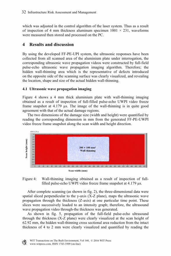
Figure 4 shows a 4 mm thick aluminium plate with wall-thinning imaging obtained as a result of inspection of full-filled pulse-echo UWPI video freeze frame snapshot at 4.179 µs. The image of the wall-thinning is in quite good agreement with that of the actual damage regions. The two dimensions of the damage size (width and height) were quantified by reading the corresponding dimension in mm from the generated FF-PE-UWPI video freeze frame snapshot along the scan width and height direction.
Figure 4: Wall-thinning imaging obtained as a result of inspection of full-filled pulse-echo UWPI video freeze frame snapshot at 4.179 µs.
After complete scanning (as shown in fig. 2), the three-dimensional data were spatial sliced perpendicular to the y-axis (X-Z plane), maps the ultrasonic wave propagation through the thickness (Z-axis) at one particular time point. These slices were successively loaded to an intensity graph; therefore, the ultrasound wave propagation video through-the thickness was generated. As shown in fig. 5, propagation of the full-field pulse-echo ultrasound through the thickness (X-Z plane) were clearly visualized at the scan height of 62.92 mm, the hidden wall-thinning cross sectional area reduction from the intact thickness of 4 to 2 mm were clearly visualized and quantified by reading the
32 Infrastructure Risk Assessment and Management
www.witpress.com, ISSN 1743-3509 (on-line) WIT Transactions on The Built Environment, Vol 160, © 2016 WIT Press
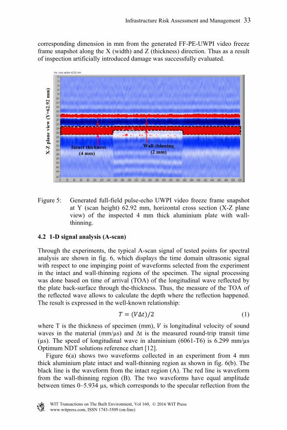
corresponding dimension in mm from the generated FF-PE-UWPI video freeze frame snapshot along the X (width) and Z (thickness) direction. Thus as a result of inspection artificially introduced damage was successfully evaluated.
Figure 5: Generated full-field pulse-echo UWPI video freeze frame snapshot at Y (scan height) 62.92 mm, horizontal cross section (X-Z plane view) of the inspected 4 mm thick aluminium plate with wall-thinning.
4.2 1-D signal analysis (A-scan)
Through the experiments, the typical A-scan signal of tested points for spectral analysis are shown in fig. 6, which displays the time domain ultrasonic signal with respect to one impinging point of waveforms selected from the experiment in the intact and wall-thinning regions of the specimen. The signal processing was done based on time of arrival (TOA) of the longitudinal wave reflected by the plate back-surface through the-thickness. Thus, the measure of the TOA of the reflected wave allows to calculate the depth where the reflection happened. The result is expressed in the well-known relationship:
∆ /2 (1)
where T is the thickness of specimen (mm), is longitudinal velocity of sound waves in the material (mm/µs) and ∆t is the measured round-trip transit time (µs). The speed of longitudinal wave in aluminium (6061-T6) is 6.299 mm/µs Optimum NDT solutions reference chart [12]. Figure 6(a) shows two waveforms collected in an experiment from 4 mm thick aluminium plate intact and wall-thinning region as shown in fig. 6(b). The black line is the waveform from the intact region (A). The red line is waveform from the wall-thinning region (B). The two waveforms have equal amplitude between times 0–5.934 µs, which corresponds to the specular reflection from the
Infrastructure Risk Assessment and Management 33
www.witpress.com, ISSN 1743-3509 (on-line) WIT Transactions on The Built Environment, Vol 160, © 2016 WIT Press

aluminium front wall. The reflection from the wall-thinning back-wall appears at around 6.571 µs. The time interval (Δt) of 5.934–6.571 µs is 0.637 µs. Then according to Eq. (1), this corresponds to a distance of approximately 2.01 mm (wall-thinning thickness). Similarly, for the intact region the time interval (Δt) of the longitudinal wave reflected by the plate back-surface through the-thickness is 1.277 µs. This corresponds to a distance of approximately 4.022 mm.
Figure 6: (a) Pulse echo waveforms collected in experiment from, (b) 4 mm thick aluminium plate specimen intact region (A), and wall-thinning region (B).
The calculated result depicts that the depth information of the plates at the intact and wall-thinning locations were efficiently evaluated by the measured round-trip transit time longitudinal laser ultrasonic signals in the time domain as well. Similarly, to examine its validity the average speed of pulse-echo through-the-thickness ultrasound at the intact and wall-thinning region were calculated and it is approximately, 6.270 mm/µs, which is very well close (99.5 %) to the theoretical speed of pulse-echo through-the-thickness ultrasound.
5 Conclusion
The full-filled pulse-echo laser ultrasonic propagation imaging system with fully non-contact scanning laser excitation and laser Doppler vibrometer sensing and UWPI image processing technique was proposed for automated damage visualization and analysis. Researchers Dhita et al. [13] pointed out that for the development of a reliable damage evaluation system, both the excitation/sensing technology and the corresponding damage analysis, and interpretation algorithm for quantitative evaluation and easy detection are equally important. The effectiveness of the proposed technique was experimentally verified by visualizing and characterizing aluminium plate with wall-thinning introduced on the opposite side of the scanning surfaces. As a result of inspection the wall-thinning was effectively detected, localized and three dimensionally quantified by using full-filled pulse-echo ultrasonic wave propagation imaging damage visualization algorithms. The approach was capable of generating FF-PE-UWPI video then producing three-dimensional detailed images of hidden wall-thinning
34 Infrastructure Risk Assessment and Management
www.witpress.com, ISSN 1743-3509 (on-line) WIT Transactions on The Built Environment, Vol 160, © 2016 WIT Press

in aluminium plate. This method generates and senses of ultrasound remotely and requires only one-sided access to the object being inspected, therefore, it could be easily reachable in difficult or tough to reach locations of structural parts. Thus, this approach or technique could be implemented in non-destructive evaluation and structural health monitoring field.
Acknowledgements
This paper was supported by the Space Core Technology Development program (2013-042548) and by the Leading Foreign Research Institute Recruitment Program (2011-0030065) through the National Research Foundation of Korea funded by the Ministry of Science, ICT and Future Planning.
References
[1] Marsh, G. Composite flying high, part one. Materials Today. April 8, 2014.
[2] Market research report, strategic business expansion of carbon fiber, Toray industries. April 12, 2005.
[3] Hola, J. and Schabowicz, K. State-of-the-art non-destructive methods for diagnostic testing of building structures anticipated development trends, Archives of civil and mechanical engineering. Vol. X, No. 3, 2010.
[4] Perez, M.A., Gil, L. and Oller, S. Non-destructive testing evaluation of low velocity impact damage in carbon fiber reinforced laminated composites, ISSN 1392-2114 ultragarsas (ultrasound) Vol. 66, No. 2, 2011.
[5] Cheng, Y., Deng, Y., Cao, J., Xiong, X., Bai, L. and Li, Z., Multi-Wave and Hybrid Imaging Techniques: A New Direction for Nondestructive Testing and Structural Health Monitoring. J. Sensors. Vol. 13, 16146-16190, 2013.
[6] Lee, C., Kim, J.W., Kim, H.K., Park, S., Visualization technique for fatigue cracks at steel structures integrating a scanning laser source with piezoelectric sensors. J. SPIE.Vol. 8692 86922D-1. 2013.
[7] Yamashita, Y., Full-Field Inspection Using Pulsed Laser for Nuclear Plants Demonstrated by Ultrasonic Simulation Using Finite Difference Method. J. Nucl. Sci. Tech. Vol. 35, No. 11: 728-734. 2007.
[8] Chia, C.C., Jang, S.G., Lee, J.R., Yoon, D.J., Structural damage identification based on laser ultrasonic propagation imaging technology. 2009. Proc. of SPIE Vol. 7389 73891S-1.
[9] Lee, J.R., Chia, C.C., Shin, H.J., Park, C.Y. and Yoon, D.J., Laser ultrasonic propagation imaging method in the frequency domain based on wavelet transformation, J. optics and lasers in engineering..volume, 49, Pages 167–175, 2011.
[10] Gan, T.H, Hutchins, D.A, Billson, D.R. and Schindel, D.W., The use of broad band acoustic transducer and pulse-compression technique for air-coupled ultrasonic imaging. J. Ultrasonics 39. 181-194, 2001.
Infrastructure Risk Assessment and Management 35
www.witpress.com, ISSN 1743-3509 (on-line) WIT Transactions on The Built Environment, Vol 160, © 2016 WIT Press
[11] Lee, J.R., and Sunuwar, N., Advances in Damage Visualization Algorithm of Ultrasonic Propagation Imaging System. J. Korean Society for Nondestructive Testing. Vol. 33, No. 2: pp. 232-240, 2013.
[12] Optimum NDT solutions reference chart, http://www.advanced-ndt.co.uk [accessed 11.01.16].
[13] Dhita, D., Lee, J.R., Park, C.Y. and Flynn, E., Laser excitation and fully non-contact sensing ultrasonic propagation imaging system for damage evaluation. J. Industrial and Commercial Applications of Smart Structures Technologies. Vol. 8343, 83430D, 2012.
36 Infrastructure Risk Assessment and Management
www.witpress.com, ISSN 1743-3509 (on-line) WIT Transactions on The Built Environment, Vol 160, © 2016 WIT Press