Design and production a special machine for manufacturing ...
Investigation of a Surface Mounted PM MachineConcept with 3D-Flux Paths, Modular Stator and
Amorphous MaterialAdolfo Garcia Gonzalez
Energy Technology DepartmentAalborg UniversityAalborg, Denmark
Dong WangEnergy Technology Department
Aalborg UniversityAalborg, Denmark
Peter Omand RasmussenEnergy Technology Department
Aalborg UniversityAalborg, Denmark
Abstract—This paper deals with the design and investigationof a surface mounted machine concept targeted at the efficientrecycling of rare-earth materials used in permanent magnets.The proposed machine has an outer rotor, single phase and amodular stator. In addition, the use of laminated iron basedamorphous material is investigated. The implementation of thistype of material in electrical machines is of interest due totheir performance in terms of reduced losses when comparedwith standard electrical steel. However, the widespread use ofamorphous materials is limited mainly due to their hardness andbrittleness that make their processing (i.e. cutting and punching)a challenging task. Hence, an alternative for the use of suchmaterial is proposed in this paper, with the combination ofboth laminated C-shaped amorphous cores and a modular stator.3D-FEM calculations of various parameters such as back-EMF,torque, inductance and losses, were validated with measurementsperformed on a demonstrator.
Index Terms—amorphous materials, magnet losses, 3D-FEM,3D-flux, modular stator, recyclability
I. INTRODUCTION
The criticality of Rare Earth Elements (REEs) has increasedawareness of the recycling of Permanent Magnet (PM) mate-rial in electrical machines [1]. Although there are methodsavailable for recycling REEs, some of them are either highenergy consuming or have a large environmental impact ormay not be used at a large scale [2]. Therefore, developingnew machine topologies with special focus on recycling of PMmaterial have obtained special interest. The machine proposedin this work is an attempt to evaluate an alternative topologywith non-traditional materials. The use of amorphous materialsin electrical machines, have been studied on various types ofmachines [3] [4] [5] [6]. Furthermore, the use of laminatedC-shaped amorphous cores has been investigated with bothFEM simulations performed on a linear machine [7] andthe experimental investigation of a claw pole transverse fluxmachine [4]. Regarding designs focused on recyclability ofelectrical machines, few work has been found [8]. Hence, themain goal of this paper is to propose an electrical machinedesign, aiming to the recyclability of the PMs, concurrentlyimplementing amorphous material. In Section II both thedefinition of the concept and the description of the working
principle are carried out. In Section III the assembly andthe model built in 3D-FEM are explained. In Section IV theresults of both calculations and measurements are presentedand discussed. In Section V conclusions are drawn and futurework is proposed.
II. DESCRIPTION OF THE PROPOSED MACHINE
A. Definition of the Concept
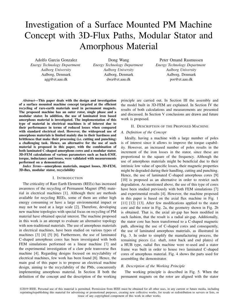
Ideally, having a machine with a large number of polesis of interest since it allows to improve the torque capabil-ity. However, an increased number of poles results in theincrement of the iron losses in the stator, since these areproportional to the square of the frequency. Although theuse of amorphous materials might be beneficial due to theirintrinsic low value of specific losses, their magnetic propertiesmight be degraded during their handling, cutting and punching.Hence, the use of laminated C-shaped amorphous cores [9][10] is proposed as an alternative in order to restrict suchdegradation. As mentioned above, the use of this type of coreshave been studied previously with both FEM simulations [7]and experimental results [4]. However, the machine proposedin this paper is based on the axial flux machine in Fig. 1[11] [12] [13]. After few modifications applied to the statorcore and the rotor in Fig. 2a, the geometry shown in Fig. 2bis obtained. That is, the axial air-gap has been modified insuch fashion, that the result is a radial air-gap. Additionally,the stator core has been transformed to a C-shaped magneticpath, allowing the use of C-shaped cores and consequently,the use of laminated amorphous materials, as illustrated inFig. 3. In order to simplify the manufacturing process, theremaining pieces (i.e. shaft, rotor back and end plates) ofa HUB type, radial flux machine were re-used and a statorframe was built in order to house two laminated C-shapedcores of amorphous material. Fig. 4 shows the parts used forassembling the demonstrator.
B. Description of the Working Principle
The working principle is described in Fig. 5. When thepermanent magnets on the rotor are aligned with the stator
©2019 IEEE. Personal use of this material is permitted. Permission from IEEE must be obtained for all other uses, in any current or future media, includingreprinting/republishing this material for advertising or promotional purposes, creating new collective works, for resale or redistribution to servers or lists, or
reuse of any copyrighted component of this work in other works.
PM
Stator
Core
Winding
Rotor
Back
Fig. 1: Double sided internal salientpole stator and external twin rotorAFM.
(a)
(b)
Fig. 2: Definition of the geometry ofthe machine proposed.
Fig. 3: C-shaped iron based lami-nated amorphous material 2605SA1[9].
Fig. 4: Assembly of the demonstra-tor.
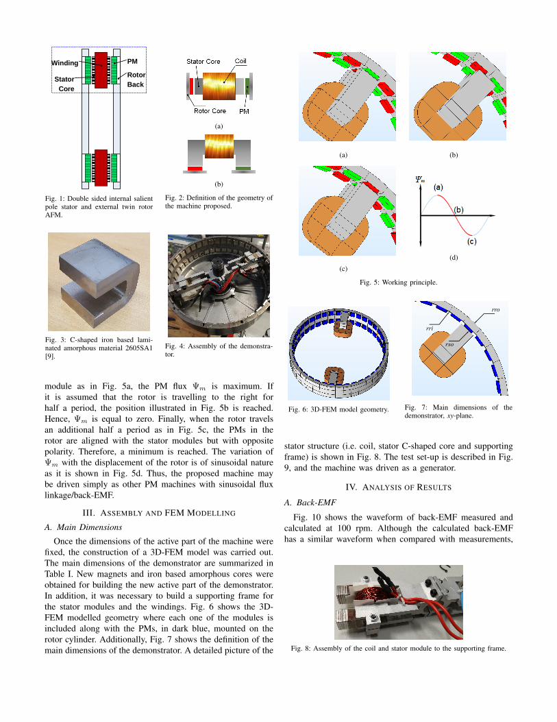
module as in Fig. 5a, the PM flux Ψm is maximum. Ifit is assumed that the rotor is travelling to the right forhalf a period, the position illustrated in Fig. 5b is reached.Hence, Ψm is equal to zero. Finally, when the rotor travelsan additional half a period as in Fig. 5c, the PMs in therotor are aligned with the stator modules but with oppositepolarity. Therefore, a minimum is reached. The variation ofΨm with the displacement of the rotor is of sinusoidal natureas it is shown in Fig. 5d. Thus, the proposed machine maybe driven simply as other PM machines with sinusoidal fluxlinkage/back-EMF.
III. ASSEMBLY AND FEM MODELLING
A. Main Dimensions
Once the dimensions of the active part of the machine werefixed, the construction of a 3D-FEM model was carried out.The main dimensions of the demonstrator are summarized inTable I. New magnets and iron based amorphous cores wereobtained for building the new active part of the demonstrator.In addition, it was necessary to build a supporting frame forthe stator modules and the windings. Fig. 6 shows the 3D-FEM modelled geometry where each one of the modules isincluded along with the PMs, in dark blue, mounted on therotor cylinder. Additionally, Fig. 7 shows the definition of themain dimensions of the demonstrator. A detailed picture of the
(a) (b)
(c)
(d)
Fig. 5: Working principle.
Fig. 6: 3D-FEM model geometry.
rro
rri
rso
Fig. 7: Main dimensions of thedemonstrator, xy-plane.
stator structure (i.e. coil, stator C-shaped core and supportingframe) is shown in Fig. 8. The test set-up is described in Fig.9, and the machine was driven as a generator.
IV. ANALYSIS OF RESULTS
A. Back-EMF
Fig. 10 shows the waveform of back-EMF measured andcalculated at 100 rpm. Although the calculated back-EMFhas a similar waveform when compared with measurements,
Fig. 8: Assembly of the coil and stator module to the supporting frame.
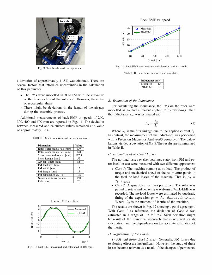
Fig. 9: Test bench used for experiment.
a deviation of approximately 11.8% was obtained. There areseveral factors that introduce uncertainties in the calculationof this parameter.
• The PMs were modelled in 3D-FEM with the curvatureof the inner radius of the rotor rri. However, these areof rectangular shape.
• There might be deviations in the length of the air-gapduring the assembly process.
Additional measurements of back-EMF at speeds of 200,300, 400 and 500 rpm are reported in Fig. 11. The deviationbetween measured and calculated values remained at a valueof approximately 12%.
TABLE I: Main dimensions of the demonstrator.
Dimension ValueRotor outer radius rro [mm] 139Rotor inner radius rri [mm] 128Stator outer radius rso [mm] 127.5Stack Length [mm] 52Air-gap length [mm] 0.5PM thickness [mm] 3PM width [mm] 15PM length [mm] 15PM remanence Br [T] 1.37Number of turns per coil 150Pole pairs 20
0 1 2 3
·10−2
−2
−4
−6
2
4
6
8
0
time [s]
Bac
k-em
f[V
]
Back-EMF vs. time
Measured3D-FEM
Fig. 10: Back-EMF measured and calculated at 100 rpm.
100 200 300 400 500
5
10
15
20
25
Speed [rpm]
Bac
k-em
f[V
]
Back-EMF vs. speed
Measured3D-FEM
Fig. 11: Back-EMF measured and calculated at various speeds.
TABLE II: Inductance measured and calculated.
Inductance [mH]Measured 11.33D-FEM 10.3
B. Estimation of the Inductance
For calculating the inductance, the PMs on the rotor weremodelled as air and a current applied to the windings. Thenthe inductance La was estimated as:
La =λaIa
(1)
Where λa is the flux linkage due to the applied current Ia.In contrast, the measurement of the inductance was performedwith a Precision Magnetics Analyzer© equipment. The calcu-lations yielded a deviation of 8.9%.The results are summarizedin Table II.
C. Estimation of No-Load Losses
The no-load losses p0 (i.e. bearings, stator iron, PM and ro-tor back losses) were measured with two different approaches:• Case 1: The machine running at no-load. The product of
torque and mechanical speed of the rotor corresponds tothe total no-load losses of the machine. That is, p0 =T0 · ωmech.
• Case 2: A spin down test was performed. The rotor waspulled to rotate and decaying waveform of back-EMF wasrecorded. The no-load losses were estimated by quadraticfitting of the expression p0 = Jm · dωmech/dt · ωmech.Where Jm is the moment of inertia of the machine.
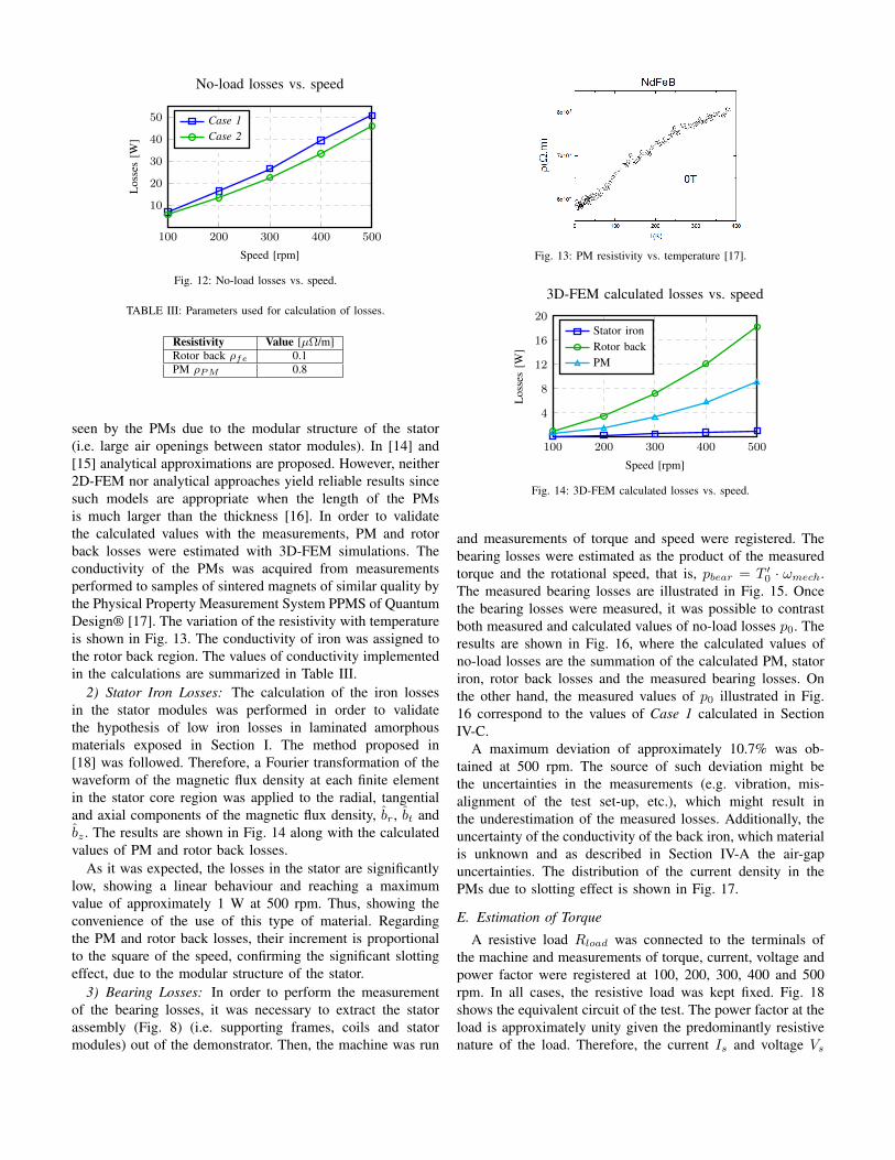
The results are shown in Fig. 12 showing a good agreement.With Case 1 as reference, the deviation of Case 2 wasestimated in a range of 9.7 to 19%. Such deviation mightbe result of the numerical approach that is required for itscalculation, and the dependence on the accurate estimation ofthe inertia.
D. Segregation of the Losses
1) PM and Rotor Back Losses: Generally, PM losses dueto slotting effect are insignificant. However, the study of theselosses become relevant as a result of the changes of permeance
100 200 300 400 500
10
20
30
40
50
Speed [rpm]
Los
ses
[W]
No-load losses vs. speed
Case 1Case 2
Fig. 12: No-load losses vs. speed.
TABLE III: Parameters used for calculation of losses.
Resistivity Value [µΩ/m]Rotor back ρfe 0.1PM ρPM 0.8
seen by the PMs due to the modular structure of the stator(i.e. large air openings between stator modules). In [14] and[15] analytical approximations are proposed. However, neither2D-FEM nor analytical approaches yield reliable results sincesuch models are appropriate when the length of the PMsis much larger than the thickness [16]. In order to validatethe calculated values with the measurements, PM and rotorback losses were estimated with 3D-FEM simulations. Theconductivity of the PMs was acquired from measurementsperformed to samples of sintered magnets of similar quality bythe Physical Property Measurement System PPMS of QuantumDesign® [17]. The variation of the resistivity with temperatureis shown in Fig. 13. The conductivity of iron was assigned tothe rotor back region. The values of conductivity implementedin the calculations are summarized in Table III.
2) Stator Iron Losses: The calculation of the iron lossesin the stator modules was performed in order to validatethe hypothesis of low iron losses in laminated amorphousmaterials exposed in Section I. The method proposed in[18] was followed. Therefore, a Fourier transformation of thewaveform of the magnetic flux density at each finite elementin the stator core region was applied to the radial, tangentialand axial components of the magnetic flux density, br, bt andbz . The results are shown in Fig. 14 along with the calculatedvalues of PM and rotor back losses.
As it was expected, the losses in the stator are significantlylow, showing a linear behaviour and reaching a maximumvalue of approximately 1 W at 500 rpm. Thus, showing theconvenience of the use of this type of material. Regardingthe PM and rotor back losses, their increment is proportionalto the square of the speed, confirming the significant slottingeffect, due to the modular structure of the stator.
3) Bearing Losses: In order to perform the measurementof the bearing losses, it was necessary to extract the statorassembly (Fig. 8) (i.e. supporting frames, coils and statormodules) out of the demonstrator. Then, the machine was run
Fig. 13: PM resistivity vs. temperature [17].
100 200 300 400 500
4
8
12
16
20
Speed [rpm]
Los
ses
[W]
3D-FEM calculated losses vs. speed
Stator ironRotor backPM
Fig. 14: 3D-FEM calculated losses vs. speed.
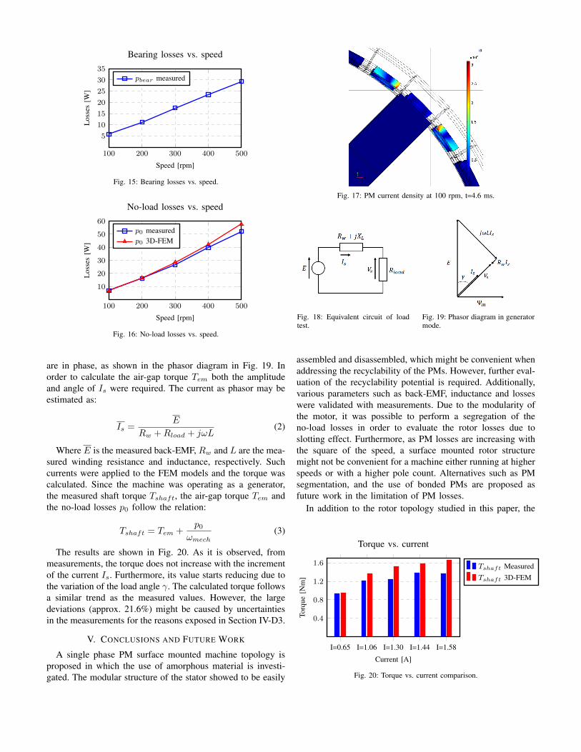
and measurements of torque and speed were registered. Thebearing losses were estimated as the product of the measuredtorque and the rotational speed, that is, pbear = T ′0 · ωmech.The measured bearing losses are illustrated in Fig. 15. Oncethe bearing losses were measured, it was possible to contrastboth measured and calculated values of no-load losses p0. Theresults are shown in Fig. 16, where the calculated values ofno-load losses are the summation of the calculated PM, statoriron, rotor back losses and the measured bearing losses. Onthe other hand, the measured values of p0 illustrated in Fig.16 correspond to the values of Case 1 calculated in SectionIV-C.
A maximum deviation of approximately 10.7% was ob-tained at 500 rpm. The source of such deviation might bethe uncertainties in the measurements (e.g. vibration, mis-alignment of the test set-up, etc.), which might result inthe underestimation of the measured losses. Additionally, theuncertainty of the conductivity of the back iron, which materialis unknown and as described in Section IV-A the air-gapuncertainties. The distribution of the current density in thePMs due to slotting effect is shown in Fig. 17.
E. Estimation of Torque
A resistive load Rload was connected to the terminals ofthe machine and measurements of torque, current, voltage andpower factor were registered at 100, 200, 300, 400 and 500rpm. In all cases, the resistive load was kept fixed. Fig. 18shows the equivalent circuit of the test. The power factor at theload is approximately unity given the predominantly resistivenature of the load. Therefore, the current Is and voltage Vs
100 200 300 400 500
5
10
15
20
25
30
35
Speed [rpm]
Los
ses
[W]
Bearing losses vs. speed
pbear measured
Fig. 15: Bearing losses vs. speed.
100 200 300 400 500
10
20
30
40
50
60
Speed [rpm]
Los
ses
[W]
No-load losses vs. speed
p0 measuredp0 3D-FEM
Fig. 16: No-load losses vs. speed.
are in phase, as shown in the phasor diagram in Fig. 19. Inorder to calculate the air-gap torque Tem both the amplitudeand angle of Is were required. The current as phasor may beestimated as:
Is =E
Rw +Rload + jωL(2)
Where E is the measured back-EMF, Rw and L are the mea-sured winding resistance and inductance, respectively. Suchcurrents were applied to the FEM models and the torque wascalculated. Since the machine was operating as a generator,the measured shaft torque Tshaft, the air-gap torque Tem andthe no-load losses p0 follow the relation:
Tshaft = Tem +p0
ωmech(3)
The results are shown in Fig. 20. As it is observed, frommeasurements, the torque does not increase with the incrementof the current Is. Furthermore, its value starts reducing due tothe variation of the load angle γ. The calculated torque followsa similar trend as the measured values. However, the largedeviations (approx. 21.6%) might be caused by uncertaintiesin the measurements for the reasons exposed in Section IV-D3.
V. CONCLUSIONS AND FUTURE WORK
A single phase PM surface mounted machine topology isproposed in which the use of amorphous material is investi-gated. The modular structure of the stator showed to be easily
Fig. 17: PM current density at 100 rpm, t=4.6 ms.
Fig. 18: Equivalent circuit of loadtest.
Fig. 19: Phasor diagram in generatormode.
assembled and disassembled, which might be convenient whenaddressing the recyclability of the PMs. However, further eval-uation of the recyclability potential is required. Additionally,various parameters such as back-EMF, inductance and losseswere validated with measurements. Due to the modularity ofthe motor, it was possible to perform a segregation of theno-load losses in order to evaluate the rotor losses due toslotting effect. Furthermore, as PM losses are increasing withthe square of the speed, a surface mounted rotor structuremight not be convenient for a machine either running at higherspeeds or with a higher pole count. Alternatives such as PMsegmentation, and the use of bonded PMs are proposed asfuture work in the limitation of PM losses.
In addition to the rotor topology studied in this paper, the
I=0.65 I=1.06 I=1.30 I=1.44 I=1.58
0.4
0.8
1.2
1.6
Current [A]
Torq
ue[N
m]
Torque vs. current
Tshaft MeasuredTshaft 3D-FEM
Fig. 20: Torque vs. current comparison.
geometry presented in Fig. 2b allows further modifications.Consequently, it would be possible to consider various rotortopologies (e.g. interior permanent magnet). Hence, the per-manent magnets would be protected from the variation of thepermeance of the air-gap, which might be beneficial in thereduction of the PM losses.
Unfortunately, the re-use of the parts of a larger motorintroduced a large value of bearing losses, which results ina low value of efficiency for this demonstrator (approximately30%). However, this might be improved by the constructionof a complete 3-phase machine, adding stator modules tothe structure, consequently improving the torque production.Finally, the concept was demonstrated to work and showed afair agreement with the calculated values.
ACKNOWLEDGMENT
The research leading to the results presented in this articlehas been funded by the European Community’s Horizon 2020Programme ([H2010/2014-2019]) under Grant Agreement no.674973 (MSCA-ETN DEMETER). This publication reflectsonly the authors view, exempting the Community from anyliability. Project website http://etn-demeter.eu/.
REFERENCES
[1] T. Elwert, D. Goldmann, F. Roemer, and S. Schwarz, “Recycling ofndfeb magnets from electric drive motors of (hybrid) electric vehicles,”Journal of Sustainable Metallurgy, vol. 3, no. 1, pp. 108–121, Mar2017. [Online]. Available: https://doi.org/10.1007/s40831-016-0085-1
[2] Y. Yang, A. Walton, R. Sheridan, K. Guth, R. Gauß, O. Gutfleisch,M. Buchert, B.-M. Steenari, T. Van Gerven, P. T. Jones, andK. Binnemans, “Ree recovery from end-of-life ndfeb permanentmagnet scrap: A critical review,” Journal of Sustainable Metallurgy,vol. 3, no. 1, pp. 122–149, Mar 2017. [Online]. Available:https://doi.org/10.1007/s40831-016-0090-4
[3] Y. Enomoto, M. Ito, H. Koharagi, R. Masaki, S. Ohiwa, C. Ishihara,and M. Mita, “Evaluation of experimental permanent-magnet brushlessmotor utilizing new magnetic material for stator core teeth,” IEEETransactions on Magnetics, vol. 41, no. 11, pp. 4304–4308, Nov 2005.
[4] N. Dehlinger and M. R. Dubois, “Clawpole transverse flux machineswith amorphous stator cores,” in 2008 18th International Conference onElectrical Machines, Sep. 2008, pp. 1–6.
[5] Z. Wang, Y. Enomoto, M. Ito, R. Masaki, S. Morinaga, H. Itabashi,and S. Tanigawa, “Development of a permanent magnet motor utilizingamorphous wound cores,” IEEE Transactions on Magnetics, vol. 46,no. 2, pp. 570–573, Feb 2010.
[6] N. Ertugrul, R. Hasegawa, W. L. Soong, J. Gayler, S. Kloeden, andS. Kahourzade, “A novel tapered rotating electrical machine topologyutilizing cut amorphous magnetic material,” IEEE Transactions onMagnetics, vol. 51, no. 7, pp. 1–6, July 2015.
[7] J. Ou, Y. Liu, M. Schiefer, and M. Doppelbauer, “A novel pm-free high-speed linear machine with amorphous primary core,” IEEE Transactionson Magnetics, vol. 53, no. 11, pp. 1–8, Nov 2017.
[8] M. Alatalo, S. T. Lundmark, and E. A. Grunditz, “Electric machinedesign for traction applications considering recycling aspects-review andnew solution,” in IECON 2011 - 37th Annual Conference of the IEEEIndustrial Electronics Society, Nov 2011, pp. 1836–1841.
[9] L. Hitachi Metals America, “Amorphous and Nanocrystalline-POWERLITE C-Cores,” [Online]: https://www.hitachimetals.com/materials-products/amorphous-nanocrystalline/ powerlite-c-cores.php,October 2016, [Accessed]: Sept. 22, 2018.
[10] L. Advanced Technology & Materials Co., “Antaimo amorphous c-cores,” [Online]: http://www.atmcn.com/Subsidiary/Metal/Products/3237.shtml, February 2018, [Accessed]: Sept. 22, 2018.
[11] J. F. Gieras, R. J. Wang, and M. J. Kamper, Axial Flux PermanentMagnet Brushless Machines. Dordrecht: Springer Netherlands, 2008.
[12] M. Aydin, S. Huang, and T. Lipo, “Axial flux permanent magnet discmachines: A review,” Conf. Record of SPEEDAM, 01 2004.
[13] Y. Limited, “Yasa p400r series e-motor,” [Online]:https://www.yasa.com/wp-content/uploads/2018/01/YASA P400 Product Sheet.pdf, 2018, [Accessed]: Mar. 01, 2019.
[14] A. Bettayeb, R. Kaczmarek, and J.-C. Vannier, “Analytical estimationof rotor loss due to stator slotting of synchronous pm machines,” WorldAcademy of Science, Engineering and Technology, vol. 66, 2010.
[15] Z. X. Fang, Z. Q. Zhu, L. J. Wu, and Z. P. Xia, “Simple and accurateanalytical estimation of slotting effect on magnet loss in fractional-slotsurface-mounted pm machines,” in 2012 XXth International Conferenceon Electrical Machines, Sep. 2012, pp. 464–470.
[16] A. G. Gonzalez, J. Millinger, and J. Soulard, “Magnet losses in inverter-fed two-pole pm machines,” in 2016 XXII International Conference onElectrical Machines (ICEM), Sept 2016, pp. 1854–1860.
[17] A. G. Gonzalez, A. K. Jha, Z. Li, P. Upadhayay, and P. Rasmussen,“Validation of efficiency maps of an outer rotor surface mountedpermanent magnet machine for evaluation of recyclability of magnets,”in 2018 IEEE International Magnetic Conference (INTERMAG), April2018, pp. 1–6.
[18] H. Domeki, Y. Ishihara, C. Kaido, Y. Kawase, S. Kitamura, T. Shimo-mura, N. Takahashi, T. Yamada, and K. Yamazaki, “Investigation ofbenchmark model for estimating iron loss in rotating machine,” IEEETransactions on Magnetics, vol. 40, no. 2, pp. 794–797, March 2004.


![Tru Laser [Basic Machine Operation & PM]](https://static.fdocuments.net/doc/165x107/55cf96ef550346d0338ebed1/tru-laser-basic-machine-operation-pm.jpg)