Inverter / Charger with Solar Charge Controller€¦ · Inverter / Charger with Solar Charge...
40
Inverter / Charger with Solar Charge Controller Steca Solarix PLI Installation and operating instructions GB further languages available at www.steca.com Z01 | 17.21
Transcript of Inverter / Charger with Solar Charge Controller€¦ · Inverter / Charger with Solar Charge...

Inverter / Charger
with Solar Charge Controller
Steca Solarix PLI
Installation and operating instructions
GB further languages available at www.steca.com
Z01 | 17.21
Steca Solarix PLI 5000-48 Instructions, Page 0
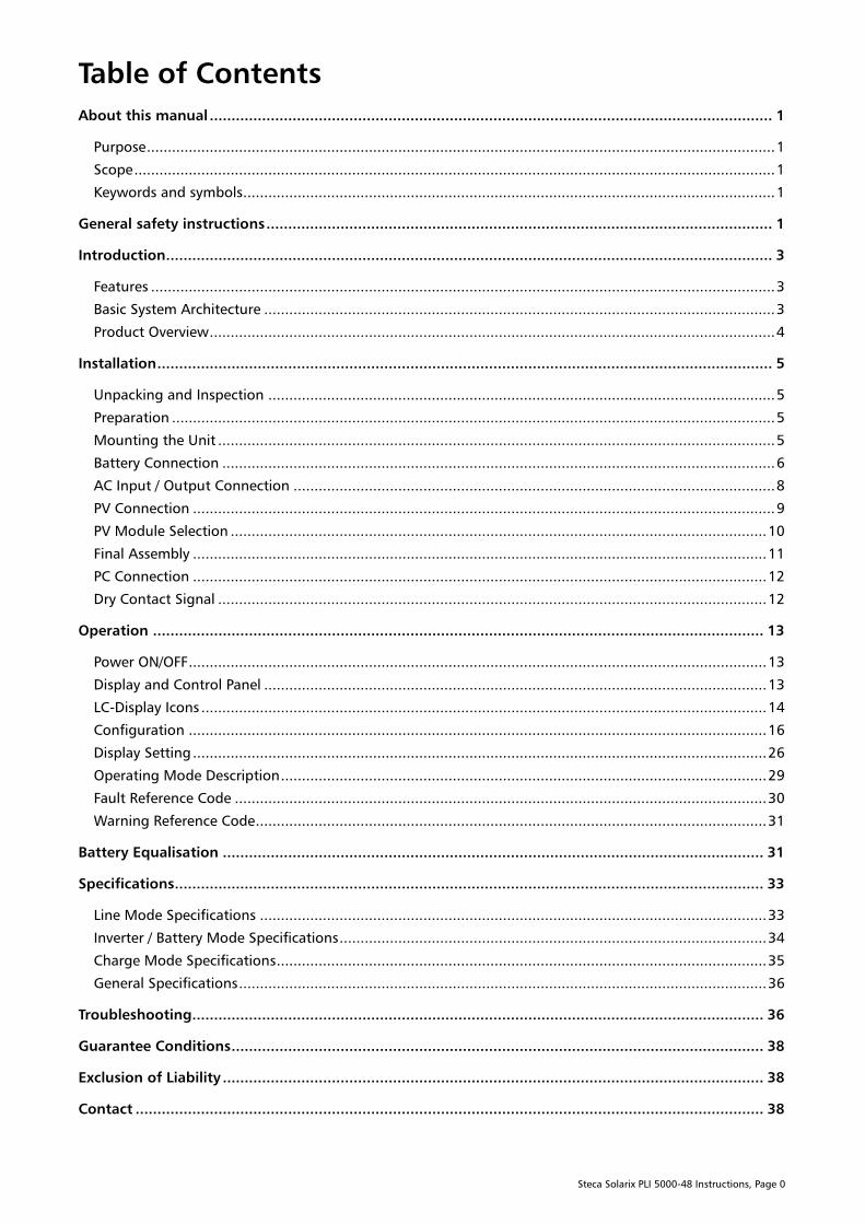
Table of Contents
About this manual ................................................................................................................................. 1
Purpose ...................................................................................................................................................... 1
Scope ......................................................................................................................................................... 1
Keywords and symbols............................................................................................................................... 1
General safety instructions .................................................................................................................... 1
Introduction ........................................................................................................................................... 3
Features ..................................................................................................................................................... 3
Basic System Architecture .......................................................................................................................... 3
Product Overview ....................................................................................................................................... 4
Installation ............................................................................................................................................. 5
Unpacking and Inspection ......................................................................................................................... 5
Preparation ................................................................................................................................................ 5
Mounting the Unit ..................................................................................................................................... 5
Battery Connection .................................................................................................................................... 6
AC Input / Output Connection ................................................................................................................... 8
PV Connection ........................................................................................................................................... 9
PV Module Selection ................................................................................................................................ 10
Final Assembly ......................................................................................................................................... 11
PC Connection ......................................................................................................................................... 12
Dry Contact Signal ................................................................................................................................... 12
Operation ............................................................................................................................................ 13
Power ON/OFF .......................................................................................................................................... 13
Display and Control Panel ........................................................................................................................ 13
LC-Display Icons ....................................................................................................................................... 14
Configuration .......................................................................................................................................... 16
Display Setting ......................................................................................................................................... 26
Operating Mode Description .................................................................................................................... 29
Fault Reference Code ............................................................................................................................... 30
Warning Reference Code .......................................................................................................................... 31
Battery Equalisation ............................................................................................................................ 31
Specifications....................................................................................................................................... 33
Line Mode Specifications ......................................................................................................................... 33
Inverter / Battery Mode Specifications ...................................................................................................... 34
Charge Mode Specifications ..................................................................................................................... 35
General Specifications .............................................................................................................................. 36
Troubleshooting ................................................................................................................................... 36
Guarantee Conditions .......................................................................................................................... 38
Exclusion of Liability ............................................................................................................................ 38
Contact ................................................................................................................................................ 38
Steca Solarix PLI 5000-48 Instructions, Page 1
About this manual
Purpose
This manual describes the assembly, installation, operation and troubleshooting of this unit (also referred
to as “inverter” throughout this manual). Please read this manual carefully before installation and
operation. Keep this manual for future reference.
Scope
This manual provides safety and installation guidelines as well as information on wiring and operation.
Keywords and symbols
These keywords are used in this manual with the following meanings:
Keyword Description
DANGER Immediate danger of death or serious bodily injury
WARNING Possible danger of death or serious bodily injury
CAUTION Possible danger of light or medium bodily injury or damage to equipment
This symbol indicates a warning or danger, pay particular attention to these sections.
General safety instructions
WARNING: This chapter contains important safety and operating instructions. Read
and keep this manual for future reference.
1. This document is part of the product.
2. CAUTION Only qualified service professionals may perform the installation work described in this
manual.
3. Before using the unit, read all instructions and cautionary markings on the unit, the batteries and
all appropriate sections of this manual.
4. CAUTION To reduce risk of injury, charge only rechargeable deep-cycle lead-acid batteries with
liquid electrolyte, AGM or gel. Other types of batteries may burst, causing personal injury and
damage, if they are not approved by Steca Elektronik. Use only batteries with 48 Vdc nominal
voltage.
5. Do not disassemble the unit, doing so may cause damage to the unit, personal injury and leads to a
total loss of warranty. Contact your dealer when service or repair is required. Incorrect re-assembly
may result in a risk of electric shock or fire.
6. To reduce risk of electric shock, disconnect all wirings before attempting any maintenance or
cleaning. Turning off the unit will not reduce this risk.
7. CAUTION Never charge a damaged or frozen battery.
8. CAUTION For optimum operation of this unit, please follow the required specification to select
appropriate cable sizes. Failure to do so may cause damage.
9. Be very cautious when working with metal tools on or around batteries. A potential risk exists in
short-circuiting batteries or other electrical parts, potentially causing an explosion or fire. Use only
insulated tools.
Steca Solarix PLI 5000-48 Instructions, Page 2
10. Please strictly follow installation procedure when connecting or disconnecting AC or DC terminals.
Please refer to the ”Installation” section of this manual for the details.
11. WARNING Ensure that all cables, particularly the AC input, AC output, photovoltaic (PV) and
battery cables are seated properly in their contacts and tightened correctly. No cable insulation may
protrude into the corresponding cable terminals. Any materials other than the cable / cable lug /
ring terminal inserted into the terminals could cause excessive heating, damage and / or fire.
12. Make sure to use a battery fuse as close as possible to the battery terminal with a rating of 250 to
300 A DC as over-current protection for the battery and battery cables. The fuse must be able to
reliably protect the battery cables from short-circuit or overload.
13. WARNING This inverter is required to be connected to a permanent grounded wiring system via the
appropriate terminals. Failure to do so may cause serious personal injury. Be sure to comply with
local requirements and regulations when installing this inverter.
14. Never allow the AC output and DC input to be short-circuited. Do NOT connect to the AC mains
when the DC input short circuits.
15. If one of the following components is damaged immediately take the device out of operation and
disconnect it from the AC mains, battery and PV modules: the device itself (not functioning, visible
damage, smoke, penetration of liquid etc.), connected cables or solar modules.
Do not switch the system on again before the device has been repaired by a dealer or the
manufacturer, damaged cables or solar modules have been repaired by a technical specialist.
16. Any use of this product aside from its intended purpose as described in this manual could lead to
damage and/or serious personal injury. Opening any part of the device apart from the bottom cover
as described in this manual will void the warranty and can lead to damage and/or serious personal
injury.
17. Only for indoor use, pollution degree 2.
18. CAUTION Heavy device. Take care when lifting the device to avoid injury.

Steca Solarix PLI 5000-48 Instructions, Page 3
Introduction
This is a multi-function inverter/charger, combining functions of off-grid inverter, MPPT solar charger, AC
transfer from an AC source to AC loads, and a battery charger from an AC source to offer an uninterruptible
power supply with a compact size. Its comprehensive LC-display offers user-configurable and
easily-accessible button configuration as well as a readout of relevant data.
Features
Pure sine wave inverter
Built-in MPPT solar charge controller
Configurable AC input voltage range limit for home appliances or personal computers
Configurable battery charging current based on applications via LCD setting
Configurable AC / solar charger priority via LCD / button setting
Compatible with AC voltage from the grid or generator power
Uninterruptible power supply in case of grid black-out
Bipolar disconnection from the AC input in inverter mode, grid injection is not technically possible
Overload, over-temperature and short-circuit protection
Smart multi-stage battery charger with optional equalisation for optimised battery performance
Cold start function (starting with only battery power and no AC source or PV modules attached)
Basic System Architecture
The following illustration shows the basic application for this unit. It also includes the following devices to
have a complete running system: battery, generator or utility (if both are used in a single system an external
source-selector is required as shown in Fig. 1), and / or PV modules.
Consult with your system integrator for other possible system architectures depending on your
requirements.
Figure 1: Hybrid power system
Steca Solarix PLI 5000-48 Instructions, Page 4
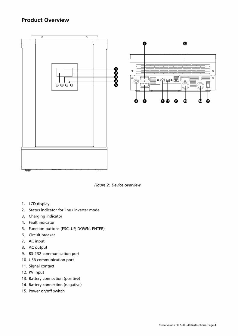
Product Overview
Figure 2: Device overview
1. LCD display
2. Status indicator for line / inverter mode
3. Charging indicator
4. Fault indicator
5. Function buttons (ESC, UP, DOWN, ENTER)
6. Circuit breaker
7. AC input
8. AC output
9. RS-232 communication port
10. USB communication port
11. Signal contact
12. PV input
13. Battery connection (positive)
14. Battery connection (negative)
15. Power on/off switch
Steca Solarix PLI 5000-48 Instructions, Page 5
Installation
Unpacking and Inspection
Before installation, please inspect the unit. Be sure that nothing inside the package is damaged. Included
items:
The inverter unit
User manual
USB communication cable
RS-232 communication cable
Ring terminal (3x)
Software CD
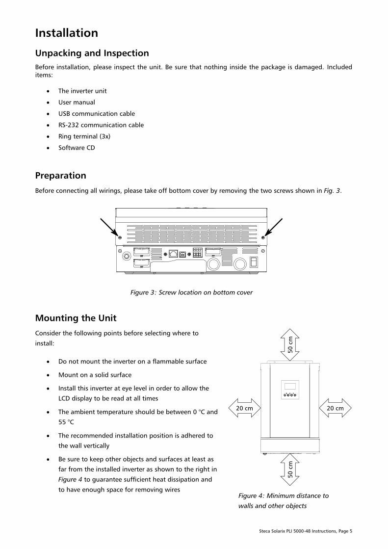
Preparation
Before connecting all wirings, please take off bottom cover by removing the two screws shown in Fig. 3.
Figure 3: Screw location on bottom cover
Mounting the Unit
Consider the following points before selecting where to
install:
Do not mount the inverter on a flammable surface
Mount on a solid surface
Install this inverter at eye level in order to allow the
LCD display to be read at all times
The ambient temperature should be between 0 °C and
55 °C
The recommended installation position is adhered to
the wall vertically
Be sure to keep other objects and surfaces at least as
far from the installed inverter as shown to the right in
Figure 4 to guarantee sufficient heat dissipation and
to have enough space for removing wires
Figure 4: Minimum distance to
walls and other objects

Steca Solarix PLI 5000-48 Instructions, Page 6
WARNING: Suitable for mounting on concrete or other non-combustible surface only.
This is a class A product. In a domestic environment this product may cause radio
interference in which case the user may be required to take adequate measures.
Fix the unit to the wall by using three M5 screws (not included) in the screw holes pictured below in Figure
5. Be sure to take precautions such as wall plugs, ensuring that the inverter’s weight can be safely held by
the wall and screws.
Figure 5: Mounting screw holes
Battery Connection
WARNING: All wiring must be performed by qualified personnel according to local
regulations.
It is very important for system safety and efficient operation to use appropriate cable
cross-sections for the battery connection. The recommended cross-section for the
battery connection is 50 mm² (at 3 metres cable length). Keep the cables between the
inverter and battery as short as possible, preferably ≤ 3 metres. Failure to tighten
connections adequately could lead to overheating or fire.
CAUTION: To ensure safe operation and regulation compliance, it is necessary to install a
separate DC fuse or circuit breaker device between battery and inverter, as close as possible
to the battery terminal. The recommended fuse or circuit breaker rating is 250 A DC to 300 A
DC, be sure to respect your local regulations.
Steca Solarix PLI 5000-48 Instructions, Page 7
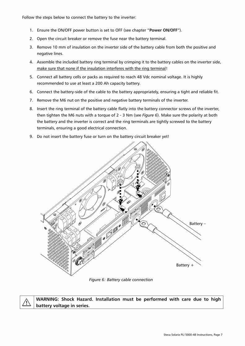
Follow the steps below to connect the battery to the inverter:
1. Ensure the ON/OFF power button is set to OFF (see chapter “Power ON/OFF”).
2. Open the circuit breaker or remove the fuse near the battery terminal.
3. Remove 10 mm of insulation on the inverter side of the battery cable from both the positive and
negative lines.
4. Assemble the included battery ring terminal by crimping it to the battery cables on the inverter side,
make sure that none if the insulation interferes with the ring terminal!
5. Connect all battery cells or packs as required to reach 48 Vdc nominal voltage. It is highly
recommended to use at least a 200 Ah capacity battery.
6. Connect the battery-side of the cable to the battery appropriately, ensuring a tight and reliable fit.
7. Remove the M6 nut on the positive and negative battery terminals of the inverter.
8. Insert the ring terminal of the battery cable flatly into the battery connector screws of the inverter,
then tighten the M6 nuts with a torque of 2 - 3 Nm (see Figure 6). Make sure the polarity at both
the battery and the inverter is correct and the ring terminals are tightly screwed to the battery
terminals, ensuring a good electrical connection.
9. Do not insert the battery fuse or turn on the battery circuit breaker yet!
Figure 6: Battery cable connection
WARNING: Shock Hazard. Installation must be performed with care due to high
battery voltage in series.
Battery +
Battery –
Steca Solarix PLI 5000-48 Instructions, Page 8
CAUTION: Do not place anything between the flat part of the inverter terminal and the ring
terminal. Otherwise, overheating and / or fire may occur.
Do not apply any anti-oxidant or other substances on the terminals before the terminals are
connected tightly.
AC Input / Output Connection
WARNING: All wiring must be performed by qualified personnel according to local
regulations.
It is very important for system safety and efficient operation to use appropriate cable
cross-sections for the AC connection. The minimum recommended cross-section for
the AC connection is 6 mm². Failure to tighten connections adequately could lead to
overheating or fire.
CAUTION: Before connecting to the AC input power source, install a separate AC breaker
between the inverter and AC input power source and turn it off. This will ensure the inverter
can be securely disconnected during maintenance and is protected from over-current from
the AC input. The recommended AC breaker rating is 40 A, follow your local regulations.
There are two terminal blocks, one marked “AC INPUT” and the other “AC OUTPUT”. Do NOT
mix the input and output connectors!
Connect a single inverter to only one phase (L and N).
Follow the steps below to connect the AC input (optional) and AC output to the inverter:
1. Before making AC input/output connection, ensure the battery DC circuit breaker is open and/or
the battery fuse is removed, thus disconnecting the battery.
2. Ensure the AC circuit breaker is open so that no conductors have voltage.
3. Remove 10 mm of insulation on the inverter side of the PE (protective earth) conductors for both
AC input and AC output. Remove 7 mm of insulation on the inverter side of the L (phase) and N
(neutral) conductors for both AC input and AC output.
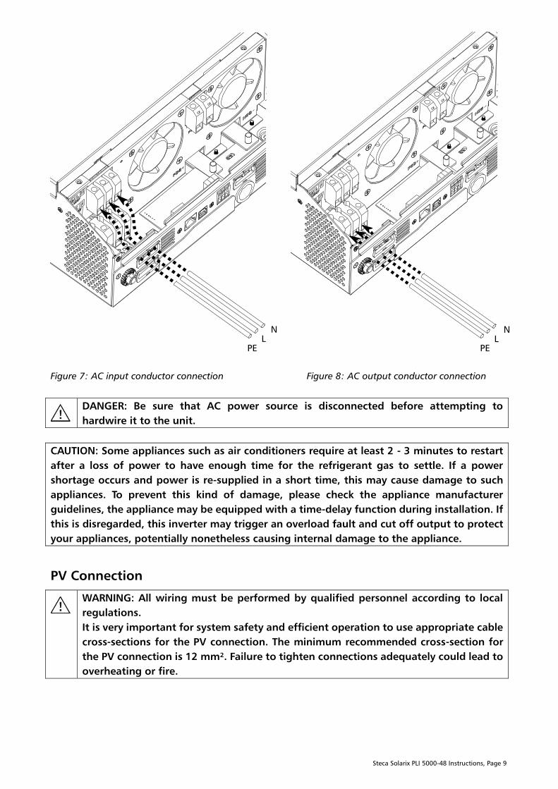
4. Connect the PE ( - protective earth) cable of the AC input (Figure 7) to the corresponding
terminal on the inverter and connect the PE ( - protective earth) conductor of the AC output
(Figure 8) to the corresponding terminal on the inverter. Tighten the terminal clamps with a torque
of 1.4 - 1.6 Nm.
5. Connect the L (phase) and N (neutral) conductors to the respective AC input (Figure 7) and AC
output (Figure 8) terminals. Tighten the terminal clamps with a torque of 1.4 - 1.6 Nm.
6. Make sure all connections are secure and tightened correctly, ensuring a good electrical
connection.
Steca Solarix PLI 5000-48 Instructions, Page 9
Figure 7: AC input conductor connection Figure 8: AC output conductor connection
DANGER: Be sure that AC power source is disconnected before attempting to
hardwire it to the unit.
CAUTION: Some appliances such as air conditioners require at least 2 - 3 minutes to restart
after a loss of power to have enough time for the refrigerant gas to settle. If a power
shortage occurs and power is re-supplied in a short time, this may cause damage to such
appliances. To prevent this kind of damage, please check the appliance manufacturer
guidelines, the appliance may be equipped with a time-delay function during installation. If
this is disregarded, this inverter may trigger an overload fault and cut off output to protect
your appliances, potentially nonetheless causing internal damage to the appliance.
PV Connection
WARNING: All wiring must be performed by qualified personnel according to local
regulations.
It is very important for system safety and efficient operation to use appropriate cable
cross-sections for the PV connection. The minimum recommended cross-section for
the PV connection is 12 mm². Failure to tighten connections adequately could lead to
overheating or fire.
N
L
PE
N
L
PE
Steca Solarix PLI 5000-48 Instructions, Page 10
CAUTION: Before connecting to the PV input, install a separate DC breaker or DC
disconnecting switch with a recommended rating of at least 80A between the inverter and
PV modules and turn it off. This will ensure the inverter can be securely disconnected during
maintenance.
It is strongly recommended to install a surge protector between the PV modules and the PV
input of the inverter to protect the PV input from over-voltage.
PV Module Selection
When selecting proper PV modules, please be sure to consider the following parameters:
1. The open-circuit voltage (Voc) of the PV array at the lowest temperatures present throughout the
year in the installation location does not exceed the maximum PV open-circuit voltage of the PV
input of the inverter.
2. The MPP voltage (Vmpp) of the PV array must be higher than the minimum PV MPP voltage of the
PV input of the inverter.
3. The total power in watt-peak (Wp) of the PV array should not exceed 1.2x the nominal charge
power of the inverter.
Follow the steps below to connect the PV input (optional) to the inverter:
1. Ensure the circuit breaker between the PV modules and the inverter side of the PV cables is open so
that there is no voltage on the PV cables before the connection.
2. Remove 10 mm of insulation on the inverter side of the battery cable from both the positive and
negative PV cables.
3. Check the correct polarity of the connection cable from the PV modules and PV input connectors
on the inverter.
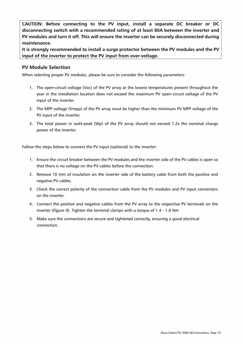
4. Connect the positive and negative cables from the PV array to the respective PV terminals on the
inverter (Figure 9). Tighten the terminal clamps with a torque of 1.4 - 1.6 Nm
5. Make sure the connections are secure and tightened correctly, ensuring a good electrical
connection.
Steca Solarix PLI 5000-48 Instructions, Page 11
Figure 9: PV array cable connection
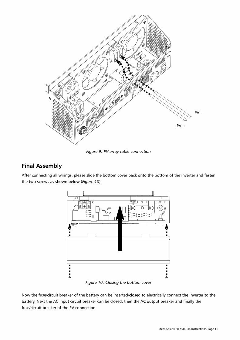
Final Assembly
After connecting all wirings, please slide the bottom cover back onto the bottom of the inverter and fasten
the two screws as shown below (Figure 10).
Figure 10: Closing the bottom cover
Now the fuse/circuit breaker of the battery can be inserted/closed to electrically connect the inverter to the
battery. Next the AC input circuit breaker can be closed, then the AC output breaker and finally the
fuse/circuit breaker of the PV connection.
PV +
PV –
Steca Solarix PLI 5000-48 Instructions, Page 12
PC Connection
If you wish to configure or monitor the inverter via a PC (optional), insert the included bundled CD into a
Windows, Linux or Mac OS X computer and follow the on-screen instructions to install the WatchPower
monitoring software. For the detailed software operation, please read the “WatchPower user manual.pdf”
file on the CD in the “Manual” folder. Now connect the supplied USB or RS-232 communication cable to the
inverter on one side and the PC on the other side.
Dry Contact Signal
There is a dry contact (up to 3 A / 250 V AC or 3 A / 30 V DC) available on the bottom panel. It hast two
possible functions:
1. When program 38 is set to “disable” (see chapter “Configuration”), it can be used to deliver a
signal to an external device (such as an AC generator) when battery voltage reaches its warning
level.
2. When program 38 is set as “enable” and the unit is working in battery / inverter mode, it can be
used to trigger an external grounding box (not included). This grounding box can then connect
neutral (N) and protective earth (PE) grounding of the AC output together.
Function 2 is useful for grid-tied installations where the AC input has a TN-C-S or TN-S grounding scheme,
so where PE and N are separate and typically a residual current device (RCD) is used for safety from electric
shock. In order for an RCD on the AC output to function, there must be a bridge between N and PE before it.
This is the case in a TN-C-S or TN-S grounding scheme. However, when the inverter is working in off-grid /
inverter mode, so when both the AC input N and L are disconnected by the internal by-pass / transfer relay,
the bridge between N and PE is no longer active. With program 38 enabled an external grounding box
controlled by the dry contact can bridge N and PE only in off-grid / inverter mode and release the bridge in
line / grid mode.
Grounding is safety-relevant and should only be done by qualified personnel. Make sure local regulations
are adhered to.
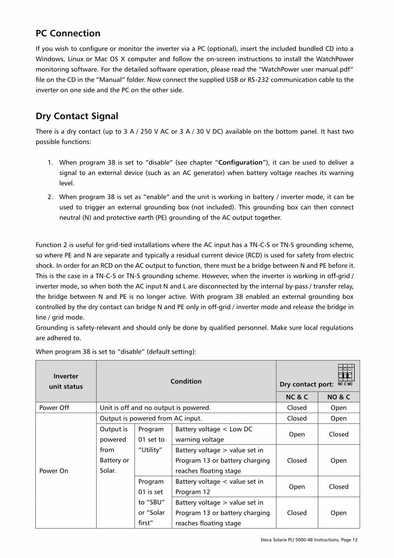
When program 38 is set to “disable” (default setting):
Inverter
unit status
Condition Dry contact port:
NC & C NO & C
Power Off Unit is off and no output is powered. Closed Open
Power On
Output is powered from AC input. Closed Open
Output is
powered
from
Battery or
Solar.
Program
01 set to
“Utility”
Battery voltage < Low DC
warning voltage
Open Closed
Battery voltage > value set in
Program 13 or battery charging
reaches floating stage
Closed Open
Program
01 is set
to “SBU”
or “Solar
first”
Battery voltage < value set in
Program 12
Open Closed
Battery voltage > value set in
Program 13 or battery charging
reaches floating stage
Closed Open

Steca Solarix PLI 5000-48 Instructions, Page 13
When program 38 is set to “enable”:
Inverter
unit status
Condition Dry contact port:
NC & C NO & C
Power Off Unit is off and no output is powered. Closed Open
Power On
Unit is in stand-by mode, line mode or fault mode Closed Open
Unit is in battery mode or power-saving mode Open Closed
Operation
Power ON/OFF
Figure 11: Power button
Once the unit has been correctly installed and the batteries are well connected, simply press the ON/OFF
switch in Figure 11 to the ON position (located on the button of the case) to turn on the inverter.
Display and Control Panel
The operation and display panel, shown in Figure 12, is on the front panel of the inverter. It includes three
LED indicator lamps, four function buttons and an LC-display, indicating the operating status.
Figure 12: Display and control panel
LC-display
LED indicators
Function buttons

Steca Solarix PLI 5000-48 Instructions, Page 14
LED Indicators
LED Indicator Meaning
Green Solid On Output is powered by AC input in line mode
Flashing Output is powered by battery or PV in battery mode
Green Solid On Battery is fully charged
Flashing Battery is charging
Red Solid On Fault condition in the inverter
Flashing Warning condition in the inverter
Function Buttons
Button Description
ESC Exit setting mode
UP Go to previous selection
DOWN Go to next selection
ENTER Confirm the selection in setting mode or enter setting mode
LC-Display Icons
Figure 13: Display
Icon Function description
Input Source Information
Indicates the AC input
Indicates the PV input
Indicates input voltage, input frequency, PV voltage, battery voltage or charger
current
Configuration Program and Fault Information
Indicates the setting programs.
Indicates the warning and fault codes.
Warning: flashing with warning code.
Fault: lighting with fault code
Steca Solarix PLI 5000-48 Instructions, Page 15
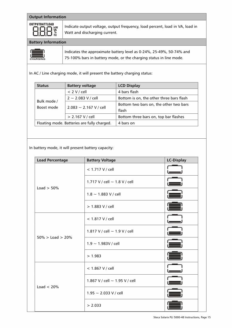
Output Information
Indicate output voltage, output frequency, load percent, load in VA, load in
Watt and discharging current.
Battery Information
Indicates the approximate battery level as 0-24%, 25-49%, 50-74% and
75-100% bars in battery mode, or the charging status in line mode.
In AC / Line charging mode, it will present the battery charging status:
Status Battery voltage LCD Display
Bulk mode /
Boost mode
< 2 V / cell 4 bars flash
2 ~ 2.083 V / cell Bottom is on, the other three bars flash
2.083 ~ 2.167 V / cell
Bottom two bars on, the other two bars
flash
> 2.167 V / cell Bottom three bars on, top bar flashes
Floating mode. Batteries are fully charged. 4 bars on
In battery mode, it will present battery capacity:
Load Percentage Battery Voltage LC-Display
Load > 50%
< 1.717 V / cell
1.717 V / cell ~ 1.8 V / cell
1.8 ~ 1.883 V / cell
> 1.883 V / cell
50% > Load > 20%
< 1.817 V / cell
1.817 V / cell ~ 1.9 V / cell
1.9 ~ 1.983V / cell
> 1.983
Load < 20%
< 1.867 V / cell
1.867 V / cell ~ 1.95 V / cell
1.95 ~ 2.033 V / cell
> 2.033
Steca Solarix PLI 5000-48 Instructions, Page 16
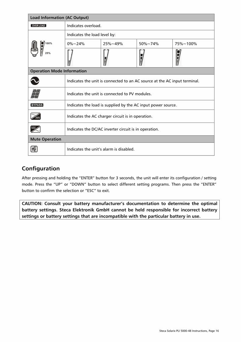
Load Information (AC Output)
Indicates overload.
Indicates the load level by:
0%~24% 25%~49% 50%~74% 75%~100%
Operation Mode Information
Indicates the unit is connected to an AC source at the AC input terminal.
Indicates the unit is connected to PV modules.
Indicates the load is supplied by the AC input power source.
Indicates the AC charger circuit is in operation.
Indicates the DC/AC inverter circuit is in operation.
Mute Operation
Indicates the unit’s alarm is disabled.
Configuration
After pressing and holding the “ENTER” button for 3 seconds, the unit will enter its configuration / setting
mode. Press the “UP” or “DOWN” button to select different setting programs. Then press the “ENTER”
button to confirm the selection or “ESC” to exit.
CAUTION: Consult your battery manufacturer’s documentation to determine the optimal
battery settings. Steca Elektronik GmbH cannot be held responsible for incorrect battery
settings or battery settings that are incompatible with the particular battery in use.
Steca Solarix PLI 5000-48 Instructions, Page 17
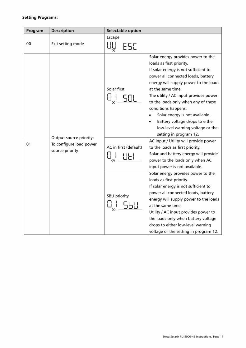
Setting Programs:
Program Description Selectable option
00 Exit setting mode
Escape
01
Output source priority:
To configure load power
source priority
Solar first
Solar energy provides power to the
loads as first priority.
If solar energy is not sufficient to
power all connected loads, battery
energy will supply power to the loads
at the same time.
The utility / AC input provides power
to the loads only when any of these
conditions happens:
Solar energy is not available.
Battery voltage drops to either
low-level warning voltage or the
setting in program 12.
AC in first (default)
AC input / Utility will provide power
to the loads as first priority.
Solar and battery energy will provide
power to the loads only when AC
input power is not available.
SBU priority
Solar energy provides power to the
loads as first priority.
If solar energy is not sufficient to
power all connected loads, battery
energy will supply power to the loads
at the same time.
Utility / AC input provides power to
the loads only when battery voltage
drops to either low-level warning
voltage or the setting in program 12.
Steca Solarix PLI 5000-48 Instructions, Page 18
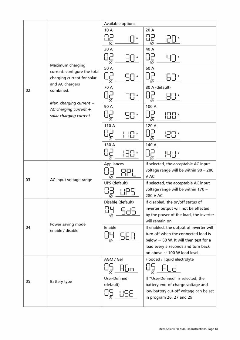
02
Maximum charging
current: configure the total
charging current for solar
and AC chargers
combined.
Max. charging current =
AC charging current +
solar charging current
Available options:
10 A
20 A
30 A
40 A
50 A
60 A
70 A
80 A (default)
90 A
100 A
110 A
120 A
130 A
140 A
03 AC input voltage range
Appliances
If selected, the acceptable AC input
voltage range will be within 90 – 280
V AC.
UPS (default)
If selected, the acceptable AC input
voltage range will be within 170 –
280 V AC.
04
Power saving mode
enable / disable
Disable (default)
If disabled, the on/off status of
inverter output will not be effected
by the power of the load, the inverter
will remain on.
Enable
If enabled, the output of inverter will
turn off when the connected load is
below ~ 50 W. It will then test for a
load every 5 seconds and turn back
on above ~ 100 W load level.
05 Battery type
AGM / Gel
Flooded / liquid electrolyte
User-Defined
(default)
If “User-Defined” is selected, the
battery end-of-charge voltage and
low battery cut-off voltage can be set
in program 26, 27 and 29.

Steca Solarix PLI 5000-48 Instructions, Page 19
06
Auto restart when overload
occurs
Irrespective of this setting
when the AC output is
short-circuited the inverter
will shut-down and
attempt to restart every 10
s. If it fails after 3 tries if
will remain off. During the
tries the AC output voltage
never exceeds 20 Vac and is
thus not dangerous to
humans.
Restart disable
(default)
Restart enable
07
Auto restart when
over-temperature occurs
Restart disable
Restart enable (default)
09 AC Output frequency
50 Hz (default)
60 Hz
11
Maximum AC input
charging current
Available options:
2 A
10 A
20 A
30 A (default)
40 A
50 A
60 A

Steca Solarix PLI 5000-48 Instructions, Page 20
12
Battery voltage below
which the inverter switches
the power source to AC in /
utility when selecting “SBU
priority” or “Solar first” in
program 01.
Available options:
44 V
45 V
46 V (default)
47 V
48 V
49 V
50 V
51 V
52 V
53 V
54 V
55 V
56 V
57 V
Steca Solarix PLI 5000-48 Instructions, Page 21
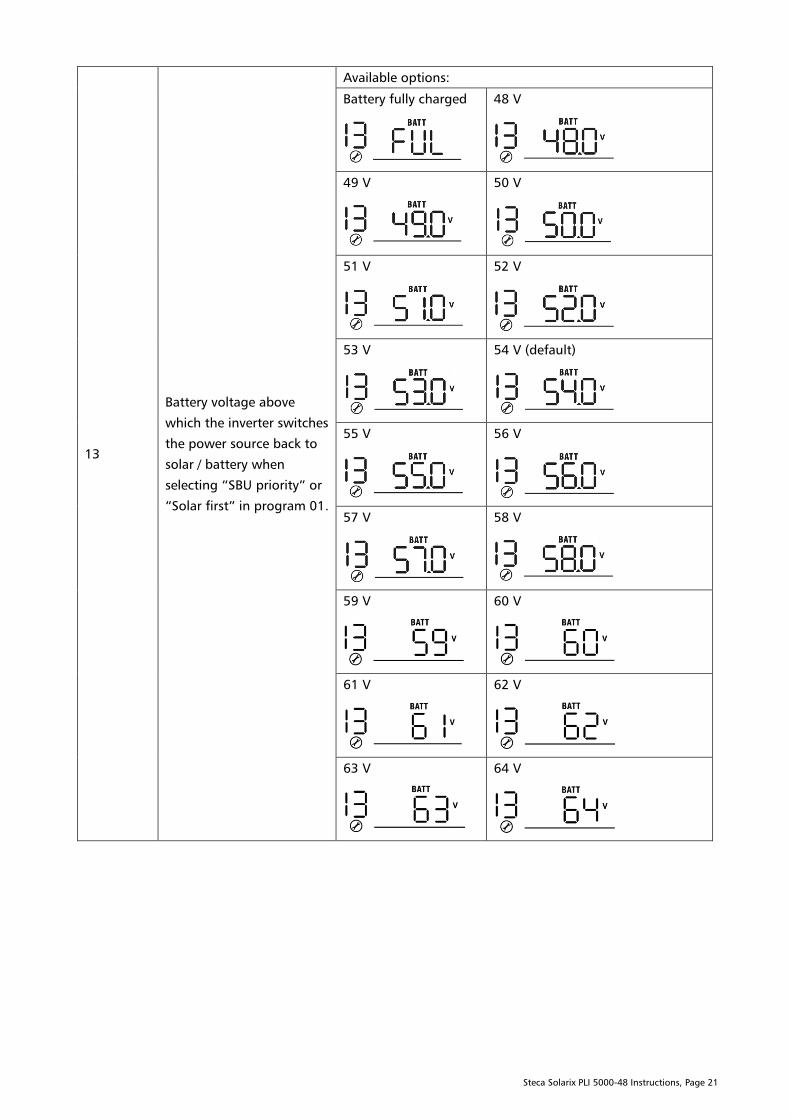
13
Battery voltage above
which the inverter switches
the power source back to
solar / battery when
selecting “SBU priority” or
“Solar first” in program 01.
Available options:
Battery fully charged
48 V
49 V
50 V
51 V
52 V
53 V
54 V (default)
55 V
56 V
57 V
58 V
59 V
60 V
61 V
62 V
63 V
64 V
Steca Solarix PLI 5000-48 Instructions, Page 22
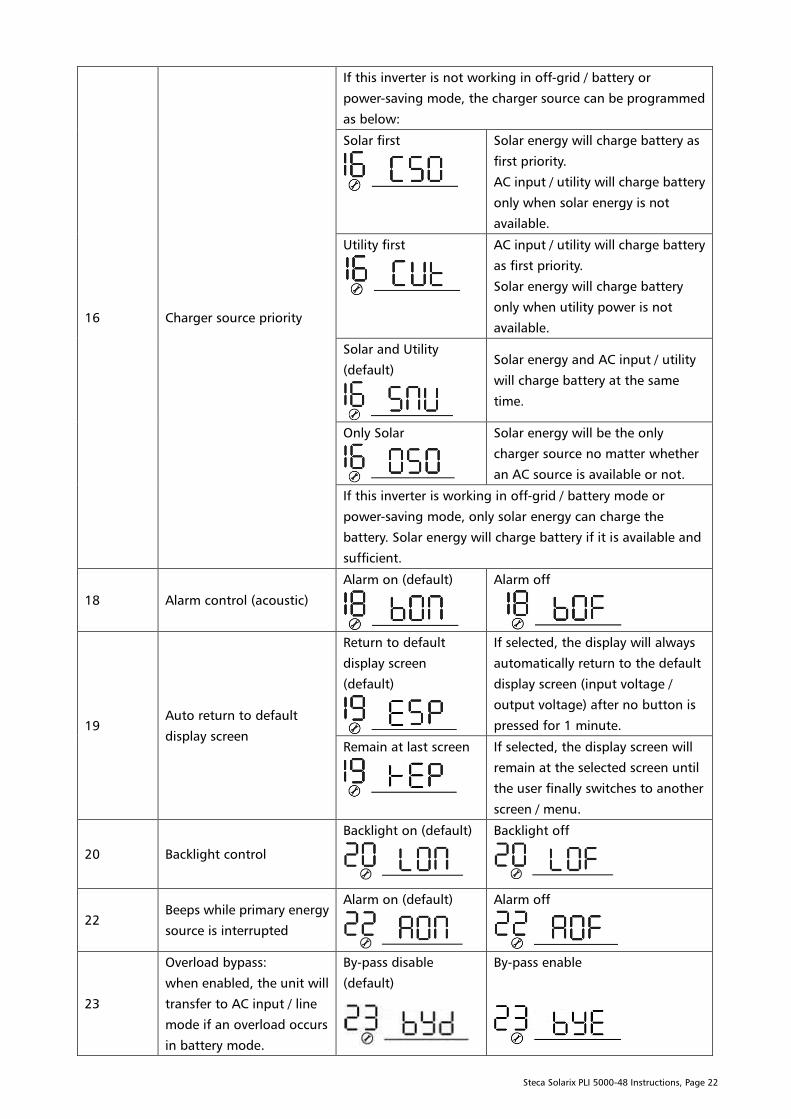
16 Charger source priority
If this inverter is not working in off-grid / battery or
power-saving mode, the charger source can be programmed
as below:
Solar first
Solar energy will charge battery as
first priority.
AC input / utility will charge battery
only when solar energy is not
available.
Utility first
AC input / utility will charge battery
as first priority.
Solar energy will charge battery
only when utility power is not
available.
Solar and Utility
(default)
Solar energy and AC input / utility
will charge battery at the same
time.
Only Solar
Solar energy will be the only
charger source no matter whether
an AC source is available or not.
If this inverter is working in off-grid / battery mode or
power-saving mode, only solar energy can charge the
battery. Solar energy will charge battery if it is available and
sufficient.
18 Alarm control (acoustic)
Alarm on (default)
Alarm off
19
Auto return to default
display screen
Return to default
display screen
(default)
If selected, the display will always
automatically return to the default
display screen (input voltage /
output voltage) after no button is
pressed for 1 minute.
Remain at last screen
If selected, the display screen will
remain at the selected screen until
the user finally switches to another
screen / menu.
20 Backlight control
Backlight on (default)
Backlight off
22
Beeps while primary energy
source is interrupted
Alarm on (default)
Alarm off
23
Overload bypass:
when enabled, the unit will
transfer to AC input / line
mode if an overload occurs
in battery mode.
By-pass disable
(default)
By-pass enable
Steca Solarix PLI 5000-48 Instructions, Page 23
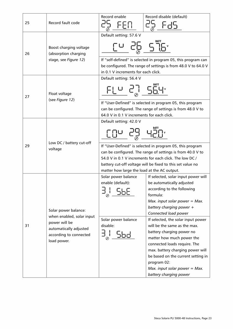
25 Record fault code
Record enable
Record disable (default)
26
Boost charging voltage
(absorption charging
stage, see Figure 12)
Default setting: 57.6 V
If “self-defined” is selected in program 05, this program can
be configured. The range of settings is from 48.0 V to 64.0 V
in 0.1 V increments for each click.
27
Float voltage
(see Figure 12)
Default setting: 56.4 V
If “User-Defined” is selected in program 05, this program
can be configured. The range of settings is from 48.0 V to
64.0 V in 0.1 V increments for each click.
29
Low DC / battery cut-off
voltage
Default setting: 42.0 V
If “User-Defined” is selected in program 05, this program
can be configured. The range of settings is from 40.0 V to
54.0 V in 0.1 V increments for each click. The low DC /
battery cut-off voltage will be fixed to this set value no
matter how large the load at the AC output.
31
Solar power balance:
when enabled, solar input
power will be
automatically adjusted
according to connected
load power.
Solar power balance
enable (default):
If selected, solar input power will
be automatically adjusted
according to the following
formula:
Max. input solar power = Max.
battery charging power +
Connected load power
Solar power balance
disable:
If selected, the solar input power
will be the same as the max.
battery charging power no
matter how much power the
connected loads require. The
max. battery charging power will
be based on the current setting in
program 02:
Max. input solar power = Max.
battery charging power

Steca Solarix PLI 5000-48 Instructions, Page 24
32
Boost charging time
(absorption charging
stage, see Figure 12)
Automatic (default):
If selected, inverter will judge this
charging time automatically.
5 minutes
The setting range is from 5 min to
900 min. The increment of each
click is 5 min.
900 minutes
If “User-Defined” is selected in program 05, this program
can be configured.
33
Battery equalisation
(see chapter “Battery
Equalisation”)
Battery equalisation enable
Battery equalisation disable
(default)
If “Flooded” or “User-Defined” is selected in program 05,
this program can be configured.
34
Battery equalization
voltage (see Figure 12)
The default setting is 60.0 V. The range of settings is from
48.0 V to 64.0 V in 0.1 V increments for each click.
35
Battery equalisation
duration (see Figure 13)
60 min (default)
The setting range is from 5
min to 900 min. The
increment of each click is 5
min.
36
Battery equalisation
timeout (see Figure 13)
120 min (default)
The setting range is from 5
min to 900 min. The
increment of each click is 5
min.
37
Battery equalisation
interval (see chapter
“Battery Equalisation”)
30 days (default)
The setting range is from 0
to 90 days. The increment of
each click is 1 day.
38
Allow neutral and
protective earth of AC
output to be connected
together:
when enabled, inverter can
deliver a signal to trigger
an external grounding box
to short neutral (N) and
protective earth (PE), see
chapter “Dry Contact
Signal” for details
Disable: dry contact is for triggering external power sources
like gensets (default)
Enable: signal to external grounding box for connecting
neutral and protective earth on AC output in battery mode
This function is only usable when the inverter is connected to
an external grounding box. When the inverter is working in
battery mode (AC input is disconnected), it will trigger the
dry contact and thus the grounding box to connect neutral
and protective earth of the AC output together.
Steca Solarix PLI 5000-48 Instructions, Page 25
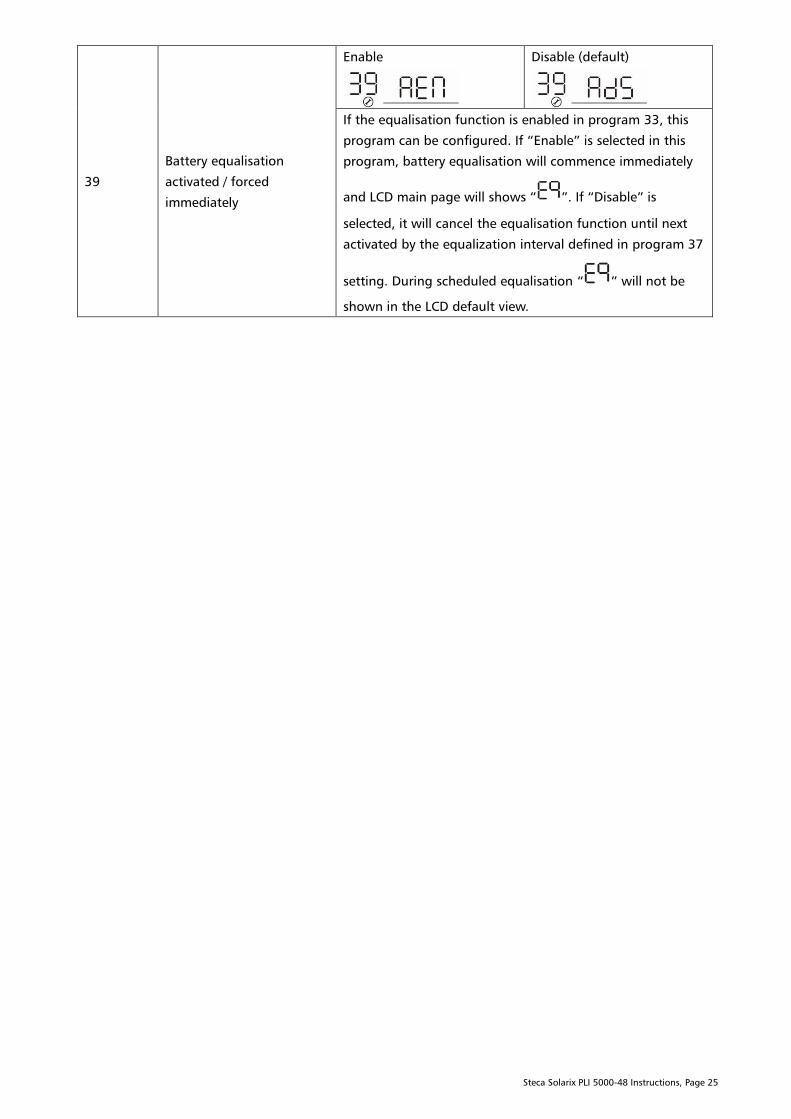
39
Battery equalisation
activated / forced
immediately
Enable
Disable (default)
If the equalisation function is enabled in program 33, this
program can be configured. If “Enable” is selected in this
program, battery equalisation will commence immediately
and LCD main page will shows “ ”. If “Disable” is
selected, it will cancel the equalisation function until next
activated by the equalization interval defined in program 37
setting. During scheduled equalisation “ ” will not be
shown in the LCD default view.
Steca Solarix PLI 5000-48 Instructions, Page 26
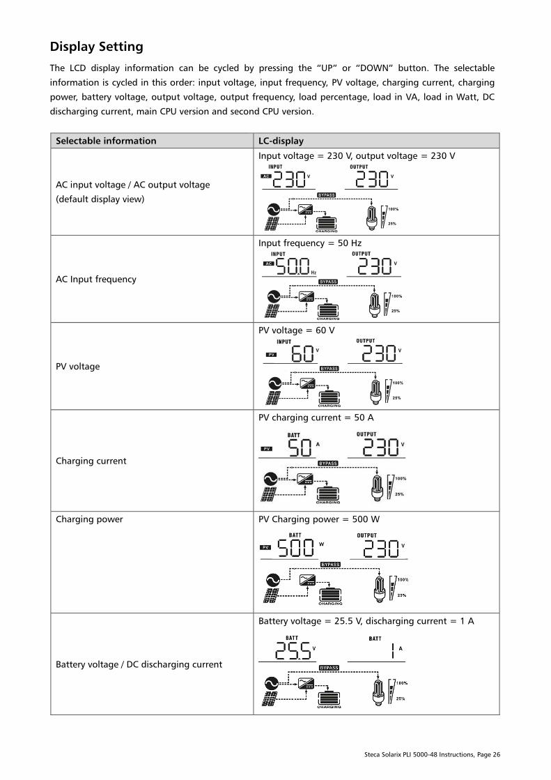
Display Setting
The LCD display information can be cycled by pressing the “UP” or “DOWN” button. The selectable
information is cycled in this order: input voltage, input frequency, PV voltage, charging current, charging
power, battery voltage, output voltage, output frequency, load percentage, load in VA, load in Watt, DC
discharging current, main CPU version and second CPU version.
Selectable information LC-display
AC input voltage / AC output voltage
(default display view)
Input voltage = 230 V, output voltage = 230 V
AC Input frequency
Input frequency = 50 Hz
PV voltage
PV voltage = 60 V
Charging current
PV charging current = 50 A
Charging power PV Charging power = 500 W
Battery voltage / DC discharging current
Battery voltage = 25.5 V, discharging current = 1 A
Steca Solarix PLI 5000-48 Instructions, Page 27
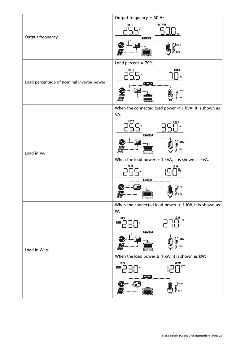
Output frequency
Output frequency = 50 Hz
Load percentage of nominal inverter power
Load percent = 70%
Load in VA
When the connected load power < 1 kVA, it is shown as
VA:
When the load power ≥ 1 kVA, it is shown as kVA:
Load in Watt
When the connected load power < 1 kW, it is shown as
W:
When the load power ≥ 1 kW, it is shown as kW:
Steca Solarix PLI 5000-48 Instructions, Page 28
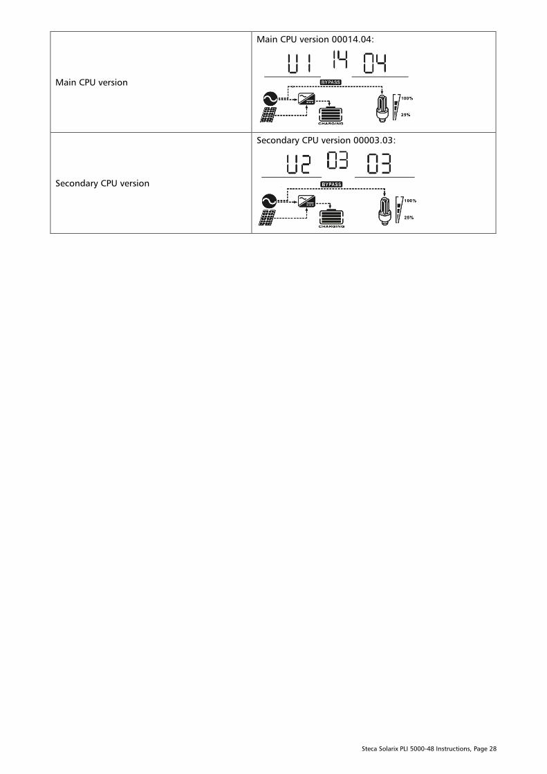
Main CPU version
Main CPU version 00014.04:
Secondary CPU version
Secondary CPU version 00003.03:

Steca Solarix PLI 5000-48 Instructions, Page 29
Operating Mode Description
Operation mode Description LC-display
Stand-by mode / power
saving mode
Note:
Stand-by mode: The
inverter is not powered
on yet but at this time,
the inverter can charge
the battery without AC
output.
Power saving mode: If
enabled, the AC output of
the inverter will be turned
off when the connected
load is below ~ 50 W and
turn back on when the
load is above ~ 100 W.
No AC output is supplied
by the unit but it can
charge batteries.
Charging by AC input and PV energy.
Charging by AC input.
Charging by PV energy.
No charging.
Fault mode
Note:
Errors are caused by
internal circuit errors or
external causes such as
over-temperature, a
short-circuited output
etc.
PV energy can charge
batteries.
Charging by PV energy.
No charging.
Line mode
The unit will provide
power from the AC input
directly to the AC output.
The inverter unit is
galvanically isolated from
both the grid neutral and
phase wires by integrated
switching relays. It can
also charge the battery in
line mode.
Charging by PV energy.
Charging from AC input.
Steca Solarix PLI 5000-48 Instructions, Page 30
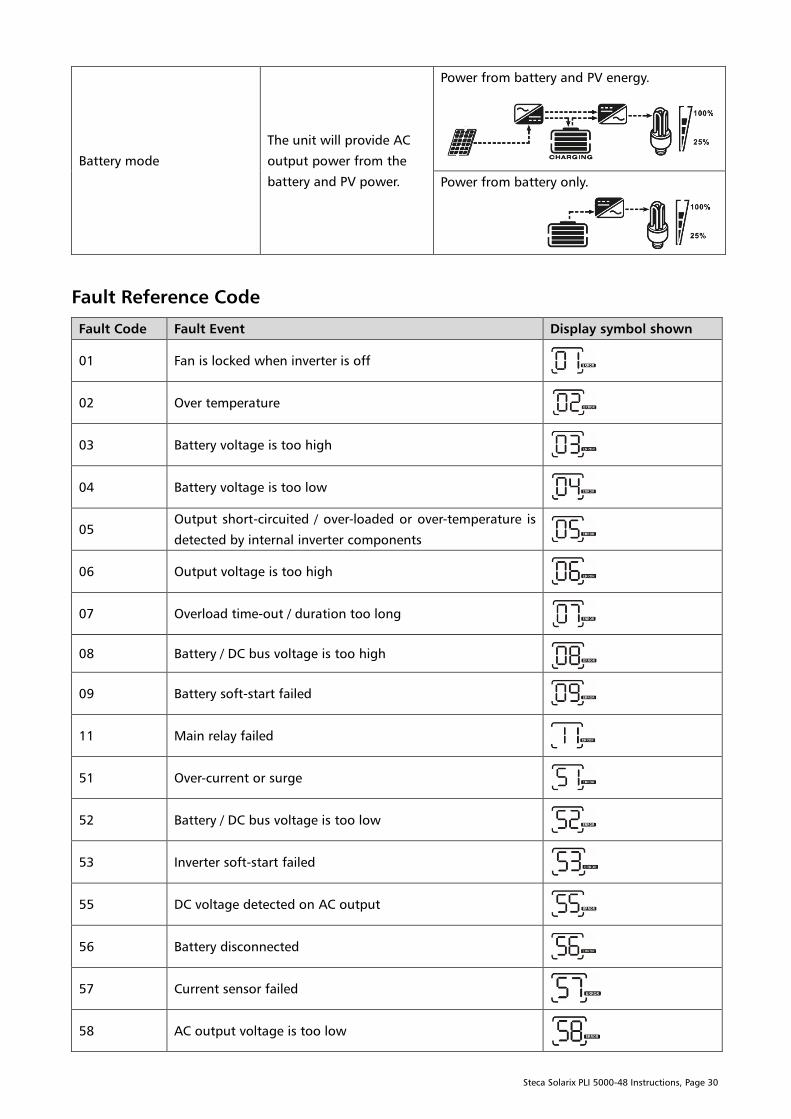
Battery mode
The unit will provide AC
output power from the
battery and PV power.
Power from battery and PV energy.
Power from battery only.
Fault Reference Code
Fault Code Fault Event Display symbol shown
01 Fan is locked when inverter is off
02 Over temperature
03 Battery voltage is too high
04 Battery voltage is too low
05
Output short-circuited / over-loaded or over-temperature is
detected by internal inverter components
06 Output voltage is too high
07 Overload time-out / duration too long
08 Battery / DC bus voltage is too high
09 Battery soft-start failed
11 Main relay failed
51 Over-current or surge
52 Battery / DC bus voltage is too low
53 Inverter soft-start failed
55 DC voltage detected on AC output
56 Battery disconnected
57 Current sensor failed
58 AC output voltage is too low

Steca Solarix PLI 5000-48 Instructions, Page 31
Warning Reference Code
Warning Code Warning Event Audible Alarm Icon flashing
01 Fan is locked when inverter is
on Beeps three times every second
03 Battery is over-charged Beeps once every second
04 Low battery voltage Beeps once every second
07 Overload Beeps once every ½ second
10 Output power derating Beeps twice every 3 seconds
12
Solar charger stopped due to
low battery voltage
13
Solar charger stopped due to
high PV voltage
14
Solar charger stopped due to
overload
Forced battery equalisation
active
Battery Equalisation
The charge controller is equipped with an equalisation function. It reverses the buildup of negative
chemical effects like stratification, a condition where acid concentration is greater at the bottom of the
battery than at the top. Equalization also helps to remove sulfate crystals that might have built up on the
plates. If left unchecked, this condition, called sulfation, will gradually reduce the overall capacity of the
battery. Therefore, it is recommended to equalise battery periodically if it is a flooded / liquid-electrolyte
type lead-acid battery. Refer to your battery manual or manufacturer for compatibility.
How to Apply the Equalisation Function
The function can be enabled in program 33, chapter “Configuration”. Once the equalisation function is
enabled it can be configured with the following parameters:
1. “Equalisation voltage” in program 34, chapter “Configuration”. This defines the desired battery
voltage during the equalisation phase.
2. “Equalisation duration” in program 35, chapter “Configuration”. This defines the duration of the
equalisation program in minutes.
3. “Equalisation timeout” in program 36, chapter “Configuration”. This defines the maximum
duration of the equalisation program in minutes. The duration may be prolonged due do voltage
fluctuations at the battery or insufficient power from the charger. This timeout ensures that the
equalisation process is stopped, at the latest after the timeout has elapsed.
4. “Equalisation interval” in program 37, chapter “Configuration”. Once the equalisation is
completed this interval defines when the charger automatically proceeds with the next equalisation
cycle.
Steca Solarix PLI 5000-48 Instructions, Page 32
5. “Battery equalisation activated / forced immediately“ in program 39, chapter “Configuration”.
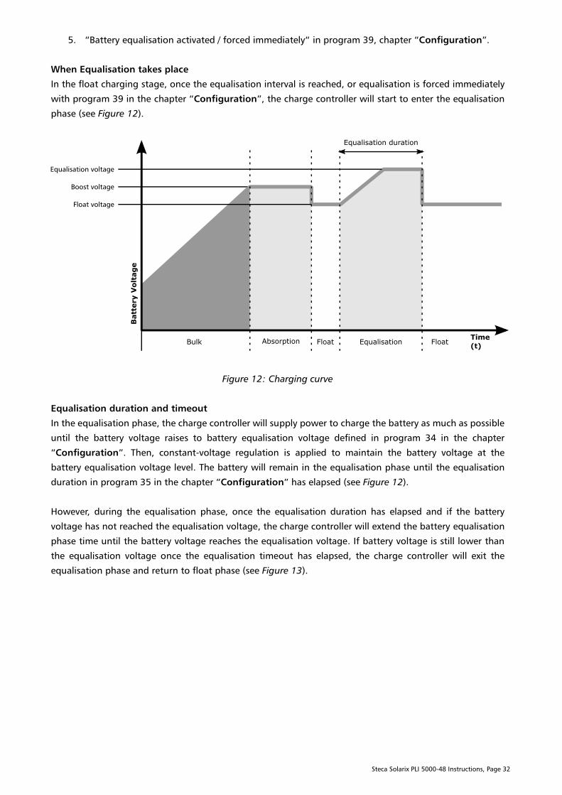
When Equalisation takes place
In the float charging stage, once the equalisation interval is reached, or equalisation is forced immediately
with program 39 in the chapter “Configuration”, the charge controller will start to enter the equalisation
phase (see Figure 12).
Figure 12: Charging curve
Equalisation duration and timeout
In the equalisation phase, the charge controller will supply power to charge the battery as much as possible
until the battery voltage raises to battery equalisation voltage defined in program 34 in the chapter
“Configuration”. Then, constant-voltage regulation is applied to maintain the battery voltage at the
battery equalisation voltage level. The battery will remain in the equalisation phase until the equalisation
duration in program 35 in the chapter “Configuration” has elapsed (see Figure 12).
However, during the equalisation phase, once the equalisation duration has elapsed and if the battery
voltage has not reached the equalisation voltage, the charge controller will extend the battery equalisation
phase time until the battery voltage reaches the equalisation voltage. If battery voltage is still lower than
the equalisation voltage once the equalisation timeout has elapsed, the charge controller will exit the
equalisation phase and return to float phase (see Figure 13).
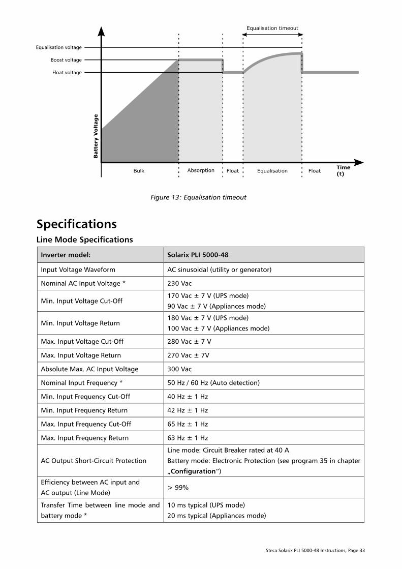
Steca Solarix PLI 5000-48 Instructions, Page 33
Figure 13: Equalisation timeout
Specifications
Line Mode Specifications
Inverter model: Solarix PLI 5000-48
Input Voltage Waveform AC sinusoidal (utility or generator)
Nominal AC Input Voltage * 230 Vac
Min. Input Voltage Cut-Off
170 Vac ± 7 V (UPS mode)
90 Vac ± 7 V (Appliances mode)
Min. Input Voltage Return
180 Vac ± 7 V (UPS mode)
100 Vac ± 7 V (Appliances mode)
Max. Input Voltage Cut-Off 280 Vac ± 7 V
Max. Input Voltage Return 270 Vac ± 7V
Absolute Max. AC Input Voltage 300 Vac
Nominal Input Frequency * 50 Hz / 60 Hz (Auto detection)
Min. Input Frequency Cut-Off 40 Hz ± 1 Hz
Min. Input Frequency Return 42 Hz ± 1 Hz
Max. Input Frequency Cut-Off 65 Hz ± 1 Hz
Max. Input Frequency Return 63 Hz ± 1 Hz
AC Output Short-Circuit Protection
Line mode: Circuit Breaker rated at 40 A
Battery mode: Electronic Protection (see program 35 in chapter
„Configuration“)
Efficiency between AC input and
AC output (Line Mode)
> 99%
Transfer Time between line mode and
battery mode *
10 ms typical (UPS mode)
20 ms typical (Appliances mode)
Steca Solarix PLI 5000-48 Instructions, Page 34
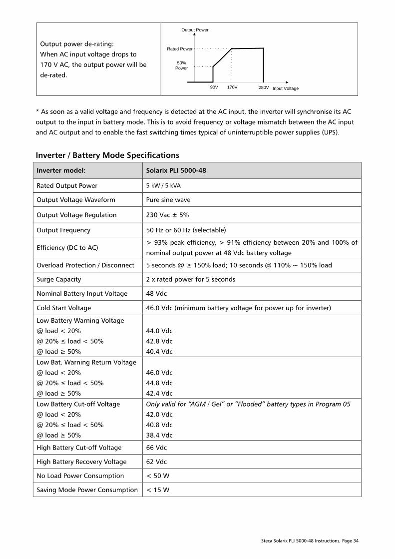
Output power de-rating:
When AC input voltage drops to
170 V AC, the output power will be
de-rated.
Input Voltage
Output Power
Rated Power
50%
Power
90V 170V 280V
* As soon as a valid voltage and frequency is detected at the AC input, the inverter will synchronise its AC
output to the input in battery mode. This is to avoid frequency or voltage mismatch between the AC input
and AC output and to enable the fast switching times typical of uninterruptible power supplies (UPS).
Inverter / Battery Mode Specifications
Inverter model: Solarix PLI 5000-48
Rated Output Power 5 kW / 5 kVA
Output Voltage Waveform Pure sine wave
Output Voltage Regulation 230 Vac ± 5%
Output Frequency 50 Hz or 60 Hz (selectable)
Efficiency (DC to AC)
> 93% peak efficiency, > 91% efficiency between 20% and 100% of
nominal output power at 48 Vdc battery voltage
Overload Protection / Disconnect 5 seconds @ ≥ 150% load; 10 seconds @ 110% ~ 150% load
Surge Capacity 2 x rated power for 5 seconds
Nominal Battery Input Voltage 48 Vdc
Cold Start Voltage 46.0 Vdc (minimum battery voltage for power up for inverter)
Low Battery Warning Voltage
@ load < 20%
@ 20% ≤ load < 50%
@ load ≥ 50%
44.0 Vdc
42.8 Vdc
40.4 Vdc
Low Bat. Warning Return Voltage
@ load < 20%
@ 20% ≤ load < 50%
@ load ≥ 50%
46.0 Vdc
44.8 Vdc
42.4 Vdc
Low Battery Cut-off Voltage
@ load < 20%
@ 20% ≤ load < 50%
@ load ≥ 50%
Only valid for “AGM / Gel” or “Flooded” battery types in Program 05
42.0 Vdc
40.8 Vdc
38.4 Vdc
High Battery Cut-off Voltage 66 Vdc
High Battery Recovery Voltage 62 Vdc
No Load Power Consumption < 50 W
Saving Mode Power Consumption < 15 W
Steca Solarix PLI 5000-48 Instructions, Page 35
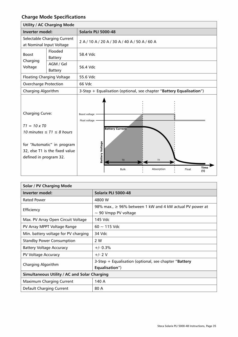
Charge Mode Specifications
Utility / AC Charging Mode
Inverter model: Solarix PLI 5000-48
Selectable Charging Current
at Nominal Input Voltage
2 A / 10 A / 20 A / 30 A / 40 A / 50 A / 60 A
Boost
Charging
Voltage
Flooded
Battery
58.4 Vdc
AGM / Gel
Battery
56.4 Vdc
Floating Charging Voltage 55.6 Vdc
Overcharge Protection 66 Vdc
Charging Algorithm 3-Step + Equalisation (optional, see chapter “Battery Equalisation”)
Charging Curve:
T1 = 10 x T0
10 minutes ≤ T1 ≤ 8 hours
for “Automatic” in program
32, else T1 is the fixed value
defined in program 32.
Solar / PV Charging Mode
Inverter model: Solarix PLI 5000-48
Rated Power 4800 W
Efficiency
98% max., ≥ 96% between 1 kW and 4 kW actual PV power at
~ 90 Vmpp PV voltage
Max. PV Array Open Circuit Voltage 145 Vdc
PV Array MPPT Voltage Range 60 ~ 115 Vdc
Min. battery voltage for PV charging 34 Vdc
Standby Power Consumption 2 W
Battery Voltage Accuracy +/- 0.3%
PV Voltage Accuracy +/- 2 V
Charging Algorithm
3-Step + Equalisation (optional, see chapter “Battery
Equalisation”)
Simultaneous Utility / AC and Solar Charging
Maximum Charging Current 140 A
Default Charging Current 80 A
Steca Solarix PLI 5000-48 Instructions, Page 36
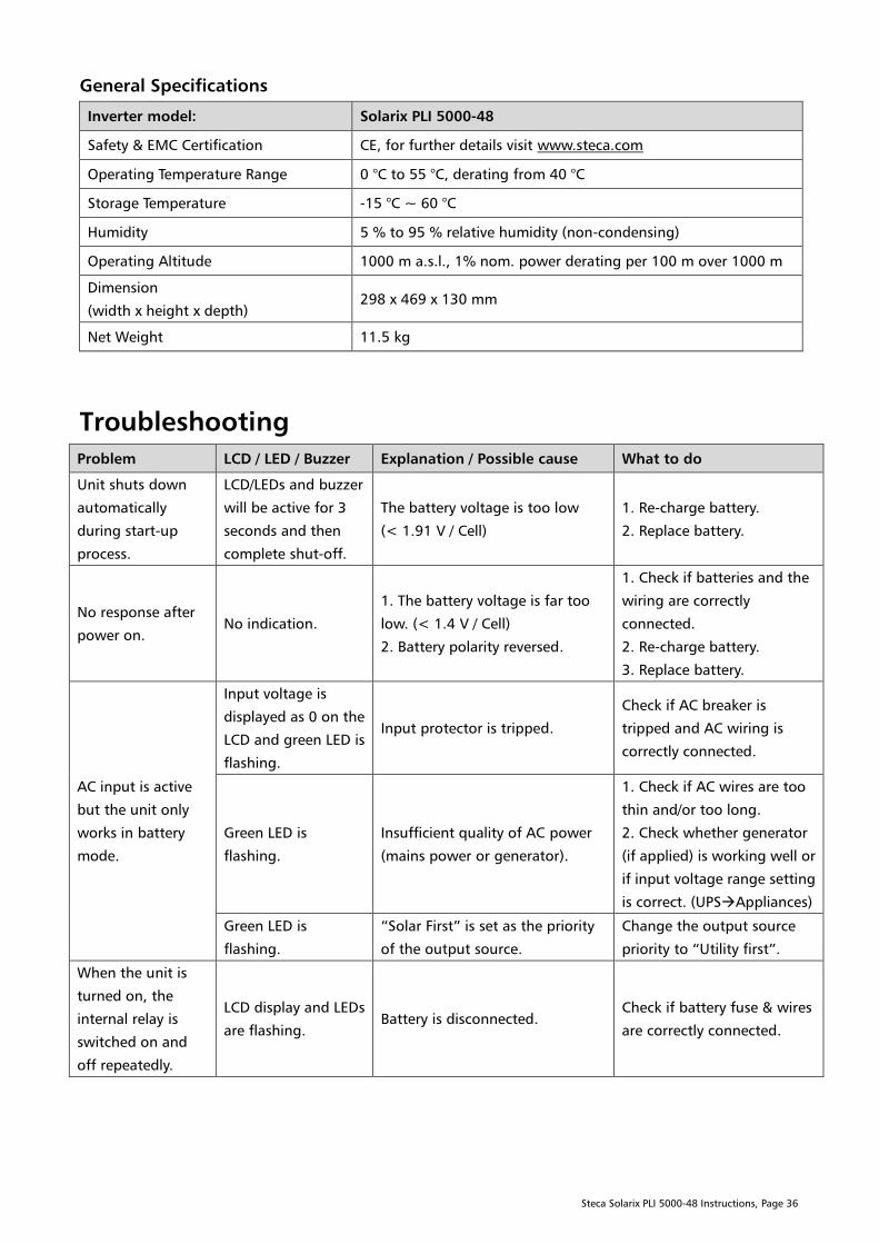
General Specifications
Inverter model: Solarix PLI 5000-48
Safety & EMC Certification CE, for further details visit www.steca.com
Operating Temperature Range 0 °C to 55 °C, derating from 40 °C
Storage Temperature -15 °C ~ 60 °C
Humidity 5 % to 95 % relative humidity (non-condensing)
Operating Altitude 1000 m a.s.l., 1% nom. power derating per 100 m over 1000 m
Dimension
(width x height x depth)
298 x 469 x 130 mm
Net Weight 11.5 kg
Troubleshooting
Problem LCD / LED / Buzzer Explanation / Possible cause What to do
Unit shuts down
automatically
during start-up
process.
LCD/LEDs and buzzer
will be active for 3
seconds and then
complete shut-off.
The battery voltage is too low
(< 1.91 V / Cell)
1. Re-charge battery.
2. Replace battery.
No response after
power on.
No indication.
1. The battery voltage is far too
low. (< 1.4 V / Cell)
2. Battery polarity reversed.
1. Check if batteries and the
wiring are correctly
connected.
2. Re-charge battery.
3. Replace battery.
AC input is active
but the unit only
works in battery
mode.
Input voltage is
displayed as 0 on the
LCD and green LED is
flashing.
Input protector is tripped.
Check if AC breaker is
tripped and AC wiring is
correctly connected.
Green LED is
flashing.
Insufficient quality of AC power
(mains power or generator).
1. Check if AC wires are too
thin and/or too long.
2. Check whether generator
(if applied) is working well or
if input voltage range setting
is correct. (UPSAppliances)
Green LED is
flashing.
“Solar First” is set as the priority
of the output source.
Change the output source
priority to “Utility first”.
When the unit is
turned on, the
internal relay is
switched on and
off repeatedly.
LCD display and LEDs
are flashing.
Battery is disconnected.
Check if battery fuse & wires
are correctly connected.
Steca Solarix PLI 5000-48 Instructions, Page 37
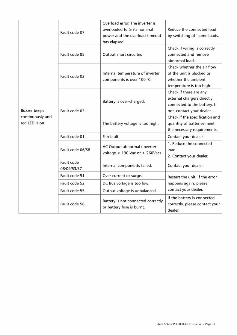
Buzzer beeps
continuously and
red LED is on.
Fault code 07
Overload error. The inverter is
overloaded to ≥ its nominal
power and the overload-timeout
has elapsed.
Reduce the connected load
by switching off some loads.
Fault code 05 Output short circuited.
Check if wiring is correctly
connected and remove
abnormal load.
Fault code 02
Internal temperature of inverter
components is over 100 °C.
Check whether the air flow
of the unit is blocked or
whether the ambient
temperature is too high.
Fault code 03
Battery is over-charged.
Check if there are any
external chargers directly
connected to the battery. If
not, contact your dealer.
The battery voltage is too high.
Check if the specification and
quantity of batteries meet
the necessary requirements.
Fault code 01 Fan fault Contact your dealer.
Fault code 06/58
AC Output abnormal (inverter
voltage < 190 Vac or > 260Vac)
1. Reduce the connected
load.
2. Contact your dealer.
Fault code
08/09/53/57
Internal components failed. Contact your dealer.
Fault code 51 Over-current or surge. Restart the unit, if the error
happens again, please
contact your dealer.
Fault code 52 DC Bus voltage is too low.
Fault code 55 Output voltage is unbalanced.
Fault code 56
Battery is not connected correctly
or battery fuse is burnt.
If the battery is connected
correctly, please contact your
dealer.

Steca Solarix PLI 5000-48 Instructions, Page 38
Guarantee Conditions
The Steca guarantee conditions are available on the Internet at:
www.steca.com/pv-off-grid/warranties
Exclusion of Liability
The manufacturer can neither monitor the compliance with this manual nor the conditions and methods
during the installation, operation, usage and maintenance of the controller. Improper installation of the
system may result in damage to property and, as a result, to bodily injury.
Therefore, the manufacturer assumes no responsibility and liability for loss, damage or costs which result
from or are in any way related to incorrect installation, improper operation, incorrect execution of
installation work and incorrect usage and maintenance.
Similarly, we assume no responsibility for patent right or other right infringements of third parties caused
by usage of this controller. The manufacturer reserves the right to make changes to the product, technical
data or installation and operating instructions without prior notice.
Contact
In the case of complaints or faults, please contact the local dealer from whom you purchased the product.
They will help you with any issues you may have.
Steca Elektronik GmbH
Mammostrasse 1
87700 Memmingen
Germany
Phone +49 (0) 8331 8558 833
Fax +49 (0) 8331 8558 132
E-mail [email protected]
Internet www.steca.com