
Inventory of Safety-Related Codes and Standards for Energy ...
142
-
Upload
truongthuan -
Category
Documents
-
view
232 -
download
4
Transcript of Inventory of Safety-Related Codes and Standards for Energy ...


PNNL-23618
Inventory of Safety-related Codes and Standards for Energy Storage Systems
with some Experiences related to Approval and Acceptance
DR Conover
September 2014
Prepared for
the U.S. Department of Energy
Energy Storage Program
under Contract DE-AC05-76RL01830
Pacific Northwest National Laboratory
Richland, Washington 99352

i

ii
Summary
Purpose
The purpose of this document is to identify laws; rules; model codes; and codes, standards, regulations
(CSR) specifications related to safety that could apply to stationary energy storage systems (ESS) and
experiences to date securing approval of ESS in relation to CSR. This information is intended to assist in
securing approval of ESS under current CSR and to identification of new CSR or revisions to existing
CSR and necessary supporting research and documentation that can foster the deployment of safe ESS.
For additional information on development and deployment of CSR see Overview of Development and
Deployment of Codes, Standards and Regulations Affecting Energy Storage System Safety in the United
States (Conover 2014).
Scope
This document is intended to cover all ESS technologies and installations. The information in this
document, highlighted in the graphic below, represents a snapshot in time of a dynamic landscape
associated with CSR development and deployment. As discussed in Section 3.0, this document will be
used for a web-based database that can be regularly updated and maintained in support of the upcoming
Strategy for Energy Storage Safety (DOE 2014). Note that safety in the context of this document includes
ensuring that an ESS installation itself is secure from unwanted access (e.g., security of the site) but does
not include software related safety (e.g., cybersecurity).
Current CSR documents that could
apply to ESS are identified, and the
scope of each document and thoughts
for future action in identifying areas
in those CSR that might need revision
(modification to existing criteria or
addition of new criteria) are
presented.1
Experiences securing approval of
ESS under current CSR are provided,
along with details associated with the
information and documentation
needed to secure approval of ESS
and any challenges associated with
the approval.
Information needed to secure the
approval of an ESS application
on the basis of equivalency with
current CSR that may not
specifically address the intended
ESS technology is provided.
1 A future activity associated with the identified documents and in response to the DOE OE Strategy for Energy
Storage Safety will include identification of needed revisions and the development and submittal of those revisions
and necessary supporting documentation to the relevant voluntary sector standards development organization
(SDO).

iii
Observations
Sections 3.0, 4.0 and 5.0 of this document support the observations listed below.
More traditional energy storage technologies (e.g., lead-acid or NiCd batteries) that have been available
for some time are currently addressed by CSR and can be more readily deployed when in compliance
with those CSR than newer energy storage technologies that may not be specifically addressed in the
current CSR.2
Newer energy storage technologies (both systems and system components) may have some standards
available to guide the evaluation of the technology for safety; if not, existing standards may need to be
revised or new standards will need to be developed as various storage technologies mature.
Standards for ESS components are important to facilitate the timely testing, review and approval of those
components and deployment of the ESS in which they are applied, especially if the ESS is not a singular
“product” but is instead an assembly of components where the ESS is constructed from those separate
components at the installation site.
Codes, standards and regulations covering the application and installation of technology tend to lag
technology development and are less likely to address newer energy storage technologies specifically,
resulting in existing criteria being inappropriately applied to ESS installations.
The development of revisions to existing CSR or new CSR can be facilitated through the development of
protocols, pre-standards, bench standards and other criteria that while not formally developed CSR can
provide a basis for acceptance in the short term and serve as a resource for future CSR development.
While an entire ESS of its component parts can be approved in the absence of specific standards upon
which to assess their safety, the process to secure such approval is challenging, not necessarily uniform,
can rely on considerable supporting research and data and may have to be repeated for each proposed
ESS installation.
Standards to address the safety of components and the entire ESS only cover the acceptability of the
component itself or the entire ESS “product” for the intended purpose but do not address the safety of the
ESS in relation to its installation environment.
An assessment of existing CSR in relation to current and anticipated ESS technology is needed to
determine where revisions are needed to those CSR, if the ESS installation and application needs to be
rethought because of those CSR and where additional research is needed to develop acceptable safety
solutions that can be included in future CSR.
Any review of current CSR and experiences associated with the approval of ESS installations under them
can foster the identification of and work on changes needed to existing and new, necessary CSR.
2 Specific current CSR are provided in Section 3.0 but include model codes published by the ICC and standards
published by NFPA, UL, LLC and others.

iv
Until CSR specifically address a particular ESS technology and those CSR are adopted, the ESS in
question will need to be assessed using alternative methods and materials (e.g., equivalent safety
performance) provisions in current CSR or other criteria that may be considered relevant by the approval
authority.
CSR covering the ESS technology and its installation must include consideration of facility management
personnel, first responders and others who will have to address any incidents created by an ESS or
impacting an ESS.
The availability of education, training and technical support will be critical to updating CSR, securing
their adoption and realizing the level of safety intended by those CSR.
The range of ESS technologies in play as to type, chemistry, size, and other factors increases the amount
of CSR related work needing to be accomplished.
The adoption and deployment of CSR can differ based on the location of the ESS in relation to the grid
and ownership of the ESS.
The purpose of CSR in protecting the public safety and welfare demands that proponents of various ESS
technologies collaborate on updating the CSR to address ESS safety.

v
Acronyms
AC alternating current
AEST Advanced Energy Storage Trial
AHJ authority having jurisdiction
AIC amps interruption current
AMCA Air Movement and Control Association
AMM alternative methods and materials
APCO Association of Public-Safety Communications Officials International
ARRA American Recovery and Reinvestment Act
ASHRAE American Society of Heating, Refrigerating and Air-Conditioning Engineers, Inc.
ASME American Society of Mechanical Engineers
ASQ American Society for Quality
ASSE American Society of Safety Engineers
ASTM American Society for Testing and Materials International
AU Australia
AWEA American Wind Energy Association
BESS battery energy storage system
BMS battery management system
B-NICE biological, nuclear, incendiary, chemical, explosive
CAGI Compressed Air & Gas Institute
CBRNE chemical, biological, radiological, nuclear, explosive
CES Community Energy Storage (Unit)
CEV controlled environmental vault
CGA Compressed Gas Association
COBRA chemical, ordinance, biological, radiological agents
CSA Canadian Standards Association
CSR codes, standards and regulations
CWA CELENEC Workshop Agreement
DOE U.S. Department of Energy
DOE OE Office of Electricity Delivery and Energy Reliability
EASA Electrical Apparatus Service Association, Inc.
EEE electronic equipment enclosure
EMC electromagnetic compatibility
EPRI Electric Power Research Institute
EPS electric power system
EPT EaglePicher Technologies
ESA Energy Storage Association
ESIC Energy Storage Integration Council
ESS energy storage systems

vi
EUC equipment under control
FAT factory acceptance testing
FEB field evaluation body
FTA Fault Tree Analysis
FMEA Failure Mode and Effects Analysis
FMECA Failure Mode, Effects and Criticality Analysis
GCI Global Change Institute
HVAC heating, ventilation, and air conditioning
HWIL Hardware in the Loop
IAPMO International Association of Plumbing & Mechanical Officials
IAS International Accreditation Service
IBC International Building Code
ICC International Code Council
I-Codes International Codes
IEC International Electrotechnical Commission
IEEE Institute of Electrical and Electronics Engineers
IFC International Fire Code
IgCC International Green Construction Code
IMC International Mechanical Code
IPC International Plumbing Code
IRC International Residential Code
ISE interconnection system equipment
ISM industrial, scientific, and medical
ISO International Standards Organization
JPR job performance requirements
LER light electric rail
LESTA large energy storage test apparatus
LEV light electric vehicle
MESA Modular Energy Storage Architecture
MSDS Material Safety Data Sheets
NAATBatt National Alliance for Advanced Technology Batteries
NBBPVI National Board of Boiler and Pressure Vessel Inspectors
NBC nuclear, biological, chemical
NBIC National Board Inspection Code
NEC National Electrical Code
NECA National Electrical Contractors Association
NEMA National Electrical Manufacturers Association
NERC North American Electric Reliability Corporation
NESC National Electrical Safety Code
NiCd nickel cadmium (battery)

vii
NFPA National Fire Protection Association
NREL National Renewable Energy Laboratory
NRTL Nationally Recognized Testing Laboratory
NWIP New Work Item Proposal
OCPD overcurrent protective device
O&M operation and maintenance
OSHA Occupational Safety and Health Administration
OSP outside plant
PCS Power Conversion System
PEARL Professional Electrical Apparatus Recyclers League
PGMA Portable Generator Manufacturers Association
PME protective multiple earthing
PV photovoltaic
PVES photovoltaic energy systems
RESS renewable energy storage system
RESU Residential Energy Storage Unit
RFID radio frequency identification
RIMS Risk & Insurance Management Society
RTDS Real Time Digital Simulation
RTU remote thermal unit
SCE Southern California Edison
SDO standards development organization
SGIA Small Generator Interconnection Agreement
SGIRM Smart Grid interoperability reference model
SWC surge withstand capability
TSP Tehachapi Storage Project
UCI University of California Irvine
UL, LLC UL Limited Liability Corporation (formerly Underwriters Laboratories, Inc.)
UMC Uniform Mechanical Code
UPC Uniform Plumbing Code
UPS uninterruptable power supply
USNC U.S. National Committee
VLA vented lead-acid (batteries)
VRLA valve regulated lead acid (batteries)
WG Working Group
WMD weapons of mass destruction

viii
Contents
Summary .............................................................................................................................................. i
Purpose .......................................................................................................................................ii
Scope ..........................................................................................................................................ii
Observations ............................................................................................................................. iii
Acronyms ............................................................................................................................................ v
1.0 Introduction ............................................................................................................................. 1.1
1.1 Background ..................................................................................................................... 1.1
1.2 Overview ......................................................................................................................... 1.1
1.3 Scope ............................................................................................................................... 1.3
1.3.1 Inventory of Codes, Standards and Regulations................................................... 1.3
1.3.2 Experiences with ESS Installation Approvals ...................................................... 1.4
1.3.3 Performance-based Review and Approval ........................................................... 1.4
2.0 Inventory of Codes, Standards and Regulations Related to ESS Safety.................................. 2.1
3.0 Codes, Standards and Regulations ........................................................................................... 3.1
3.1 Standards for ESS Components ...................................................................................... 3.1
3.2 Standards for the Entire ESS ......................................................................................... 3.13
3.3 Codes, Standards and Regulations for the Installation of an ESS ................................. 3.28
3.4 Codes, Standards and Regulations for Commissioning, Operation or Maintenance of an
ESS ................................................................................................................................ 3.47
3.5 Codes, Standards and Regulations Relevant to Incident Response Associated with an
ESS Installation ............................................................................................................. 3.53
3.6 Codes, Standards and Regulations for ESS Transportation .......................................... 3.56
4.0 Experiences with Energy Storage System Installation Approvals ........................................... 4.1
4.1 Electric Thermal Storage Systems .................................................................................. 4.2
4.2 PV Solar and Storage System Combination .................................................................... 4.2
4.3 Flow Batteries ................................................................................................................. 4.2
4.4 Hybrid Energy Storage Technology ................................................................................ 4.4
4.5 Large System AC Uninterruptable Power Systems (UPS) and Small System DC UPS . 4.6
4.6 Grid Storage Battery........................................................................................................ 4.7
4.7 Grid-Connected Premise Battery .................................................................................... 4.8
4.8 Customer Connected Premise Battery ............................................................................. 4.8
4.9 Tehachapi Storage Project ............................................................................................... 4.8
4.10 Energy Storage Installations at San Diego Gas & Electric ........................................... 4.11
4.11 Southern California Edison ........................................................................................... 4.13
4.12 Portland General Electric .............................................................................................. 4.16
5.0 Performance-based Review and Approval .............................................................................. 5.1
5.1 Unlisted ESS Components or Entire Systems ................................................................. 5.3
ix
5.2 Alternative Methods and Materials ................................................................................. 5.3
5.3 Third-party Safety Documentation .................................................................................. 5.6
6.0 Next Steps ................................................................................................................................ 6.1
6.1 Identification of Apparent Gaps in Current CSR ............................................................ 6.1
6.2 Identification of Opportunities to Revise Current CSR During 2014 ............................. 6.1
6.3 Identification of Opportunities to Revise Current CSR Beyond 2014 ............................ 6.4
6.4 Identification of Opportunities to Develop New CSR .................................................... 6.5
7.0 References ............................................................................................................................... 7.1
Appendix A Materials Relevant to Facilitate Review and Approval of ESS Installations ............. A.1
Appendix B CSR-Related Presentation Material ............................................................................ B.1
Figures
Figure 1.1. Future Deployment of Safe ESS ................................................................................... 1.2
Figure 4.1. Eaglepicher’s Demo Powerpyramid™ Installation ...................................................... 4.4
Figure 4.2. ATK BESS System ....................................................................................................... 4.5
Figure 4.3. CWEP RESS Installation .............................................................................................. 4.5
Figure 4.4. Arista Multi-Story Building, NYC ............................................................................... 4.6
Figure 4.5. ESS Installation ............................................................................................................ 4.7
Tables
Table 3.1. Standards Applicable to ESS Components .................................................................... 3.3
Table 3.2. Standards for the Entire ESS ........................................................................................ 3.14
Table 3.3. Standards for ESS Installation ...................................................................................... 3.29
Table 3.4. Standards for ESS Commissioning, Operation or Maintenance .................................. 3.48
Table 3.5. Standards Relevant to Incident Response Associated with an ESS Installation .......... 3.54
Table 3.6. Standards for ESS Transportation ................................................................................ 3.57
Table 6.1. 2014 CSR Revisions ...................................................................................................... 6.2

1.1
1.0 Introduction
1.1 Background
The U.S. Department of Energy (DOE) Office of Electricity Delivery and Energy Reliability (DOE OE)
sponsored a workshop focused on identifying the key roadblocks to acceptance of energy storage systems
(ESS) and needs associated with the validation of safety in ESS in February 2014 (Sandia and PNNL
2014). Those in attendance represented a wide range of stakeholders focused on ESS technology
development, deployment, acceptance and use. The primary objective of this event was to secure input
from ESS stakeholders on issues, needs, concerns, etc. related to the validation of ESS safety, challenges
associated with addressing ESS acceptance through revision to current codes, standards and regulations
(CSR) and what technical and policy initiatives would be needed to address those challenges. The long-
term goal supported by this DOE OE initiative is to foster the timely acceptance of ESS that ensures the
safety of the public as well as the property associated with ESS installations. The information and
recommendations derived from this workshop supported the development of safety strategy supported by
a multi-year roadmap of activities that would help realize that long-term goal.
Activities related to CSR development that address ESS safety, their adoption and deployment and the
associated support infrastructure for those CSR such as conformity assessment1 as well as needed
education and training of all stakeholders impacting ESS deployment will occur over multiple years.2
A key outcome of the workshop was the immediate need to identify short-term (~6 months to a year)
activities to foster the deployment of safe ESS installations in parallel to the development and initial
implementation of the longer-term ESS safety strategy.
This document is in response to a short-term need to identify current CSR that directly or indirectly apply
to ESS, how ESS installations have been approved to date and what areas in CSR may be needed to be
updated and revised to ensure that ESS installations are safe and can be more readily approved in the
future. Without a concerted effort to ensure standards are available to test and validate the safety of ESS
components and systems as well as CSR provisions addressing the safe installation of ESS in all intended
locations, the cost of ESS installations could increase due to a myriad of different and potentially
misapplied CSR. At worst, either CSR will be prohibitive or as ESS installations increase in number, the
probability of a safety-related incident occurring that could affect the ESS industry would increase.
1.2 Overview
A short-term activity focused on the deployment of safe ESS is to determine the existing CSR that have
been or could be applied to ESS. By conducting this inventory of existing CSR, the deployment of safe
ESS can be facilitated in the future as shown in Figure 1.1.
1 Conformity assessment is considered a number of activities such as testing, listing, labeling, certification,
accreditation, plan review, inspection and licensing that are focused on confirming that intended outcomes are
secured and ensured (e.g., documentation and verification of compliance with CSR). 2 While technologies and their associated safety impact vary, it can take up to 5 years after the conduct of research to
develop the necessary standards and model codes, secure their adoption on a widespread basis and conduct needed
education and outreach such that the technology is recognized and can be readily accepted and approved for
installation and continued use.

1.2
Figure 1.1. Future Deployment of Safe ESS

1.3
This short-term activity to foster the acceptance of safe ESS is intended to initiate a robust CSR activity
that will serve as the foundation for a longer-term CSR activity to be included in the DOE ESS Safety
Strategy developed pursuant to the February 2014 DOE ESS Safety Roadmapping Workshop (Sandia and
PNNL 2014). It is envisioned that as activities are formally initiated later in 2014 to support the safety
strategy, this document will serve as a key component in addressing the strategy and be transferred to a
web-based database providing current and anticipated actions associated with identified CSR, research
and documentation supporting CSR enhancements and information on how ESS installations are being
approved and deployed. These and other suggested next steps are outlined in Section 6.0.
1.3 Scope
As previously noted, this document is intended to form the foundation of a dynamic resource that resides
as a web-based database tied to and in support of the Strategy for Energy Storage Safety (DOE 2014). To
address the short-term need for revisions to existing CSR or development of new CSR that may be needed
to foster deployment of safe ESS, this document represents a particular view of current CSR criteria and
experiences at one point in time. It is separated into three distinct focal areas: inventory of current CSR,
experiences associated with ESS approvals under current CSR and background on performance-based
approval paths under current CSR. This document is intended to serve as a starting point that can be used
now and on which further input can be secured, resulting in a more robust source of information for future
consideration and used as a basis for future action on CSR and needed research and documentation of
ESS safety. Note that while conformity assessment1 is a key component of CSR deployment and would
involve among others testing laboratories, certification agencies, accreditation bodies, building and fire
officials and others, this document does not provide detail on conformity assessment agencies or bodies in
the same way that it provides information on SDOs. More information on conformity assessment is
available in Appendix C of the Overview of Development and Deployment of Codes, Standards and
Regulations Affecting Energy Storage System Safety in the United States (Conover 2014).
1.3.1 Inventory of Codes, Standards and Regulations
Within Section 3.0, all current CSR2 that could apply even marginally to stationary ESS technology are
identified. Identification is by document title and sponsoring organization as well as a statement of the
scope of the document and comments related to the possible application of the document to an ESS and/or
further work that may be needed to assess the need to update or enhance the document. On a longer term
basis, the actual text of the criteria (based on any needed approvals of the copyright holder) could be
included as well in the envisioned web-based database or a link provided to the standards development
organization (SDO) that publishes the CSR. The intent of this inventory is to provide a comprehensive
delineation of current CSR that could apply to ESS and in so doing assist the ESS industry to review CSR
requirements and determine if revisions are warranted and then provide guidance in development of those
revisions. Those revisions can then be pursued collaboratively by all interested parties and stakeholders.
1 Verification that what is intended is actually realized.
2 This initial document is a starting point and is intended to identify relevant CSR and provide some nominal
information about those documents. It is envisioned that through collaboration by interested parties and
stakeholders, the listing of relevant CSR will grow and additional insight into the current criteria in those documents
and necessary revisions will be pursued. One example of this evolution from information to action is a meeting of
stakeholders on June 3, 2014 in Washington, D.C. for the purpose of discussing needed revisions to the National
Electrical Code (NFPA 70) that are due on November 7, 2014 for consideration in the 2017 edition of the National
Electrical Code (NEC).

1.4
In parallel to this identification and assessment of CSR, it is envisioned within the DOE ESS Safety
Strategy (DOE 2014) that efforts will be undertaken independently to pursue testing, modeling and
analysis of ESS to determine appropriate safety-related guidance and criteria. This approach recognizes
that addressing CSR criteria associated with ESS safety must look at current CSR for guidance but also
look at ESS technology, failure modes and effects and relevant research and documentation that support
specific safety-related criteria that can inform development of appropriate safety-related CSR.
1.3.2 Experiences with ESS Installation Approvals
Section 4.0 documents how existing ESS installations, American Recovery and Reinvestment Act
(ARRA) and non-ARRA funded and both utility and customer side of the meter, were reviewed and
approved with respect to safety, the processes through which those approvals were conducted, the CSR
criteria applied, the scientific and engineering basis supporting the validation of the system’s safety and
the documentation submitted to validate ESS safety. This information was contributed from ESS
manufacturers, utilities and others involved with actual ESS installations. It is intended that this
information further reinforce that in Sections 3.0 and 5.0 with respect to development of future CSR and
securing approvals for ESS installations under current CSR.
1.3.3 Performance-based Review and Approval
Section 5.0 provides information on one approach that can be used in pursuing the acceptance of an ESS
installation under current CSR. That approach is based on achieving equivalent performance to that
resulting from compliance with current CSR (e.g., acceptance under alternative methods and materials
[AMM]). This avenue also includes standards covering the approval of unlisted electrical equipment such
as National Fire Protection Association (NFPA) 791-2012, Recommended Practice and Procedures for
Unlabeled Electrical Equipment Evaluation (ANSI 2012). The focus of this section is the AMM and
other criteria in CSR that allow for acceptance on the basis of equivalent performance, the processes
associated with applying these alternative approval approaches to technology acceptance, the criteria in
the CSR that form the basis for acceptance and the experiences to date with ESS approvals. To some
degree, Section 5.0 provides insight into securing short-term approvals where current CSR do not
specifically address an ESS technology or the experiences to date with approvals suggest approaching
approval through AMM as opposed to the literal application of the current CSR. Another approach to
performance-based review and approval is the installation and on-site acceptance testing of a stationary
ESS. This is conducted for each separate installation, and the approving authority or their agent(s) such as
an accredited third party would determine the testing to be conducted and criteria that would be used to
deem the ESS installation acceptable.

2.1
2.0 Inventory of Codes, Standards and Regulations Related to ESS Safety
As previously noted, this document is intended to provide a starting point for determining the provisions
in current CSR that apply to ESS technology and that can serve as a starting point for assessing the impact
of CSR on stationary ESS. There are separate presentations in Section 3.0 on documents covering the
following:
These are presented separately in Sections 3.1 through 3.6 because they involve different types of
documents, they each have a different and unique scope, are applied differently at different times and are
likely adopted and compliance verified by different entities.7
In the interest of ensuring nothing is missed, this inventory addresses current CSR that directly and
indirectly apply to ESS. A direct application is a provision that specifically calls out the ESS technology
and is clearly applicable to the technology. An indirect application is where the ESS technology is not
specifically named, but because of some characteristic of the ESS technology, the CSR would apply (e.g.,
limitations on storage and use of certain chemicals in buildings would be an indirect application because
the term ESS is not used in the CSR, but the existence of the chemicals in the ESS could result in
application of the CSR to the ESS) or could be used as a basis for criteria for ESS in the future.
Future work by stakeholders and interested parties pursuant to the ESS Safety Strategy (DOE 2014) that
will focus on each specific CSR document, how it currently applies to ESS and based on that assessment
what changes might be needed to update or enhance the document to address ESS more effectively. That
work will also identify areas where new CSR may be needed. In parallel to this work, research, testing,
modeling and analysis would be conducted to determine what is appropriate to address ESS safety to
inform future CSR activities (e.g., without being directed based on current CSR determine what safety-
related issues need to be addressed and how they should be addressed and with that information available
use it to support future CSR work).
The following U.S. SDOs were contacted to secure firsthand information of standards they publish
because some of their standards might have an impact on some aspect of an ESS or their scope is such
that they could develop ESS-related documents in the future. The intent was to notify these SDOs of this
ESS activity and provide them an opportunity to assist in identifying their documents that they would
want included. Many, but not all responded and given a lack of response research was conducted in an
attempt to identify relevant standards published by the SDO for inclusion in this document.
7 In the future through a web-based database, it is intended that the CSR information in Section 3.0 will be identified
and able to be sorted as to its applicability to a particular battery or technology type, ownership scenario, location
relative to the utility meter, size or other relevant factors that might limit the scope and applicability of CSR presented.

2.2
A summary of each SDO contacted is presented below, which also helps in identifying SDOs that may
have some relevance in development of CSR relevant to ESS and/or whose constituents could play a role
in deployment of safe ESS. As the focus of this document is on U.S. activities, SDOs in other countries
such as the Canadian Standards Association (CSA) are not included. The importance and value of SDOs
in other countries and regionally and globally cannot be overstated. It is envisioned after the publication
of this document and its transfer to a web-based database that SDOs in other countries can be included
along with their ESS-relevant documents.
Air Movement and Control Association International, Inc. (AMCA)
www.amca.org
AMCA is a non-profit organization of the world’s manufacturers of related air system equipment, primarily but not limited to fans, louvers, dampers, air curtains, airflow measurement stations, acoustic attenuators and other air system components for industrial, commercial and residential markets. AMCA publishes and distributes standards, references and application manuals for specifiers and engineers with an interest in air systems for the selection, evaluation and troubleshooting of air system components. Many of AMCA’s standards are accepted as American National Standards.
Association of Public-Safety Communications Officials International (APCO)
www.apcointl.org
APCO International serves the needs of public safety communications practitioners worldwide – and the welfare of the general public as a whole – by providing expertise, professional development, technical assistance, advocacy and outreach.
American Society of Heating, Refrigerating and Air-Conditioning Engineers, Inc. (ASHRAE)
www.ashrae.org
ASHRAE is a global society advancing human well-being through sustainable technology for the built environment. ASHRAE and its members focus on building systems, energy efficiency, indoor air quality, refrigeration and sustainability within the industry. Through research, standards writing, publishing and continuing education, ASHRAE shapes tomorrow’s built environment today.
American Society of Mechanical Engineers (ASME)
www.asme.org
ASME helps the global engineering community develop solutions to real-world challenges. As a non-profit professional organization, ASME enables collaboration, knowledge-sharing and skill development across all engineering disciplines, while promoting the vital role of the engineer in society. ASME codes and standards, publications, conferences, continuing education and professional development programs provide a foundation for advancing technical knowledge and a safer world.
American Society for Quality (ASQ)
www.asq.org
ASQ is a global community of people dedicated to quality who share the ideas and tools that make the world work better. With individual and organizational members around the world, ASQ provides the quality community with training, professional certifications and knowledge to a vast network of members of the global quality community.
American Society of Safety Engineers (ASSE)
www.asse.org
ASSE promotes the expertise, leadership and commitment of its members while providing them with professional development, advocacy and standards development. It also sets the occupational safety, health and environmental community’s standards for excellence and ethics. ASSE is a visible advocate for safety, health and environmental professionals through proactive government affairs at the federal and state levels, and in member-led relationships with key federal safety and health agencies.

2.3
American Society for Testing and Materials International (ASTM)
www.astm.org
ASTM International develops and delivers international voluntary consensus standards. ASTM standards are used to improve product quality, enhance safety, facilitate market access and trade, and build consumer confidence. Working in an open, transparent process and using advanced electronic infrastructure, ASTM members deliver the test methods, specifications, guides and practices that support industries and governments worldwide.
American Wind Energy Association (AWEA)
www.awea.org
AWEA developed the standards covering the safety of wind turbines. They also are a member of the U.S. National Committee (USNC) of the International Electrotechnical Commission (IEC) that serves as the focal point for U.S. parties interested in the development, promulgation and use of globally relevant standards for the wind energy industry. As the U.S. representative to the IEC TC 88 (a subcommittee specific to energy from wind turbines), AWEA serves as a conduit to the global standards-setting community for technical and policy positions arising in the United States for the IEC TC 88 and brings issues from the global arena to the United States for review, consideration and response. The scope of the IEC TC 88 is to prepare international standards for wind turbines that convert wind energy into electrical energy. These standards address design requirements, engineering integrity, measurement techniques and test procedures. Their purpose is to provide a basis for design, quality assurance and certification.
Compressed Air & Gas Institute (CAGI)
www.cagi.org
CAGI aims to be the united voice of the compressed air industry, serving as the unbiased authority on technical, educational, promotional and other matters that affect the industry.
Compressed Gas Association (CGA)
www.cganet.com
CGA represents all facets of the industry: manufacturers, distributors, suppliers and transporters of gases, cryogenic liquids and related products. CGA is dedicated to the development and promotion of safety standards and safe practices in the industrial gas industry. The work of CGA is performed by committees of volunteers from member companies having expertise in the particular areas targeted. Each of these committees focuses on work item projects through its subcommittees and task forces.
Electrical Apparatus Service Association, Inc. (EASA)
www.easa.org
EASA is a dynamic, professional trade organization that is recognized internationally as the leader in the electrical and mechanical apparatus sales, service and repair industry. They provide an ongoing flow of industry information and education that helps members worldwide serve as total solution providers for electrical and mechanical equipment and systems.
FM Global
www.fmglobal.com
FM Global provides comprehensive global commercial and industrial property insurance, engineering-driven underwriting and risk management solutions, groundbreaking property loss prevention research and prompt, professional claims handling. FM Global’s products and services directly support its clients’ overall risk management objectives through understanding the nature and reality of their specific risks; establishing sound loss prevention solutions that safeguard against loss; developing cost-effective insurance and risk transfer solutions backed by large, stable capacity; and providing the claims and loss mitigation support to minimize business disruption.

2.4
International Association of Plumbing & Mechanical Officials (The IAPMO Group)
www.iapmo.org
The IAPMO Group uses an open consensus process in the development of the Uniform Plumbing Code® and Uniform Mechanical Code®. These codes are established through scientific research, debate and analysis. The IAPMO Group provides code development assistance, education, plumbing and mechanical product testing and certification, building product evaluation and a manufacturer-preferred quality assurance program. Each component of the IAPMO Group works toward playing an integral part in protecting the health of people everywhere.
International Code Council (ICC)
www.iccsafe.org
ICC is dedicated to developing model codes and standards used in the design, build and compliance process to construct safe, sustainable, affordable and resilient structures. Published by the ICC, the International Codes (I-Codes) provide minimum safeguards for people at home, at school and in the workplace. The I-Codes are a complete set of comprehensive, coordinated building safety and fire prevention codes.
Institute of Electrical and Electronics Engineers (IEEE)
www.ieee.org
IEEE is dedicated to advancing technological innovation and excellence for the benefit of humanity. IEEE and its members inspire a global community through IEEE’s publications, conferences, technology standards and professional and educational activities.
National Board of Boiler and Pressure Vessel Inspectors (NBBPVI)
www.nationalboard.org
NBBPVI publishes the National Board Inspection Code (NBIC), which establishes rules for installation, inspection and repairs to boilers, pressure vessels and piping designed for internal or external pressure. NBBPVI’s purpose is to install and maintain the integrity of pressure retaining items, thereby ensuring that these items continue to function safely, with the ultimate goal of public and personal safety. The NBIC Committee meets regularly to consider revisions to the rules based on advancements in technology and materials, the next edition of which will be published in July 2015.
National Electrical Contractors Association (NECA)
www.necanet.org
NECA serves the management interests of the entire electrical contracting industry, which performs specialized construction work related to the design, installation and maintenance of electrical systems in a safe, effective and environmentally sound manner. NECA is dedicated to enhancing the industry through innovative research, performance standards, progressive labor relations and workforce recruiting and training.
National Electrical Manufacturers Association (NEMA)
www.nema.org
NEMA is the association of electrical equipment and medical imaging manufacturers that provide a diverse set of products used in the generation, transmission, distribution and end use of electricity as well as medical diagnostic imaging. NEMA provides a forum for the development of technical standards that are in the best interests of the industry and users, advocacy of industry policies on legislative and regulatory matters and collection, analysis and dissemination of industry data.

2.5
North American Electric Reliability Corporation (NERC)
www.nerc.com
NERC is a non-profit international regulatory authority whose mission is to ensure the reliability of the bulk power system in North America. NERC develops and enforces reliability standards; annually assesses seasonal and long-term reliability; monitors the bulk power system through system awareness; and educates, trains and certifies industry personnel. NERC is the electric reliability organization for North America subject to oversight by the Federal Energy Regulatory Commission and governmental authorities in Canada. NERC’s jurisdiction includes users, owners and operators of the bulk power system, which serves more than 334 million people.
National Fire Protection Association (NFPA)
www.nfpa.org
NFPA’s mission is to reduce the worldwide burden of fire and other hazards on the quality of life by providing and advocating consensus codes and standards, research, training and education. NFPA develops, publishes and disseminates over 300 consensus codes and standards that are intended to minimize the possibility and effects of fire and other risks.
Professional Electrical Apparatus Recyclers League (PEARL)
www.pearl1.org
PEARL is the professional organization of companies that supply quality surplus and remanufactured electrical equipment, apparatus and components. PEARL is an ANSI Accredited Standards Developer.
Portable Generator Manufacturers Association (PGMA)
www.pgmaonline.com
PGMA seeks to develop and influence safety and performance standards for portable generators sold in North America.
Risk & Insurance Management Society (RIMS)
www.rims.org
RIMS is dedicated to advancing the practice of risk management and brings networking, professional development and education opportunities to its membership.
UL Limited Liability Corporation (UL, LLC)
www.ul.com
Formerly Underwriters Laboratories, Inc. (UL), UL, LLC is an independent safety science company innovating safety solutions from the public adoption of electricity to new breakthroughs in sustainability, renewable energy and nanotechnology. Dedicated to promoting safe living and working environments, UL, LLC helps safeguard people, products and places in important ways, facilitating trade and providing peace of mind.

2.6
While not listed as SDOs, the following organizations and alliances are currently addressing safety-
related CSR relevant to ESS. Through the DOE Energy Storage Safety Strategy (DOE 2014), it is
envisioned that ESS stakeholders individually and collectively through these organizations will
collaborate in the development of CSR that foster the deployment of safe ESS.
The California Energy Storage Alliance (CESA)
CESA is a membership-based advocacy group committed to advancing the role of energy storage in the electric power sector through policy, education, outreach, and research. The mission of CESA is to make energy storage a mainstream energy resource that accelerates the adoption of renewable energy technology and promotes a more efficient, reliable, affordable, and secure electric power system. Members include technology manufacturers, project developers, systems integrators, consulting firms, and other clean tech industry leaders.
Electric Power Research Institute (EPRI) has formed an Energy Storage Integration Council (ESIC)
ESIC is a forum in which electric utilities guide a discussion with energy storage vendors, government organizations and other stakeholders to develop reliable, safe and cost-effective energy storage options for the utility industry. The ESIC was formed in 2013 by the energy storage program at EPRI, along with utilities, vendors, national laboratories and industry experts. The first general meeting was held in August 2013, and working groups have been assembled (applications, performance, system development and grid deployment) to develop common approaches to critical components supporting ESIC’s mission. The initial focus is to find common solutions to definition and deployment for distribution system-connected ESS encompassing the utility scope from customer meter to 69kV.
Energy Storage Association (ESA)
ESA represents companies that develop and deploy energy storage technologies. ESA members research, manufacture, distribute, finance and build energy storage projects domestically and abroad. ESA is comprised of over 120 private companies, non-profit organizations and individual experts working together to educate the public and inform regulators and legislators about the importance of energy storage technologies.
National Alliance for Advanced
Technology Batteries (NAATBatt)
NAATBatt is a non-profit trade association of foreign and domestic corporations, associations and research institutions focused on the manufacture of large format advanced batteries for use in transportation and large-scale energy storage applications in the United States. Members include advanced battery and electrode manufacturers, materials suppliers, vehicle makers, electric utilities, equipment vendors, service providers, universities and national laboratories. NAATBatt’s core missions are to grow the North American market for products incorporating advanced energy storage technology and to reduce the cost of those products to U.S. consumers. NAATBatt supports the adoption of public policies and the development of new technologies and industrial standards that will reduce the price of large format advanced batteries to consumers and the products that use them. NAATBatt provides a platform for battery manufacturers, advanced materials suppliers, vehicle makers, recharging solution providers and electric utilities to work together across industry boundaries to address the challenges of large-scale electrochemical energy storage.

2.7
The New York Battery and Energy Storage Technology (NY-BEST™) Consortium
NY-BEST was created in 2010 to position New York State as a global leader in energy storage technology, including applications in transportation, grid storage, and power electronics. NY-BEST currently has more than 130 members that include manufacturers, academic institutions, utilities, technology and materials developers, start-ups, government entities, engineering firms, systems integrators, and end-users. The majority of its members are New York State based entities. NY-BEST serves as an expert resource to energy storage-related companies and organizations seeking assistance to grow their businesses in New York State. This includes access to financing, research capabilities, potential partners, technology developers, manufacturers, and other private sector and government resources. NY-BEST serves as an important connector in establishing a strong energy storage “ecosystem” encompassing all stages of energy storage product development and use. The vision of NY-BEST is that sustainable energy use requires transformative energy storage solutions and NY-BEST will lead the development and deployment of these solutions by linking energy markets with our world class industries and research institutions. The mission is to catalyze and grow the energy storage industry and establish New York State as a global leader.
SunSpec Alliance and MESA Standards Alliance
These organizations have a joint effort to advance common communication standards for energy storage devices to lower costs and increase customer adoption. An industry consortium of electric utilities and technology suppliers have developed the Modular Energy Storage Architecture (MESA) and created the MESA Standards Alliance. The MESA standards are an open, non-proprietary set of specifications and standards to accelerate interoperability, scalability, safety, quality, availability and affordability in energy storage components and systems. MESA Standards focus on three key aspects of ESS design: how ES components are physically packaged and arranged; how ES components are electrically connected and how they communicate internally; and how the ESS as a whole communicates with other devices and utility control systems. These standards are complementary to SunSpec communication standards for distributed energy components and applications. The intention of MESA and SunSpec is to enable seamless integration of storage and distributed energy. The SunSpec Alliance and MESA are both industry-led trade associations working to establish common standards for the different devices that comprise photovoltaic (PV) power systems and energy storage systems. Working together, the two associations are developing and extending smart grid standards that work for industry participants on both the utility and customer side of the meter.

3.1
3.0 Codes, Standards and Regulations
This section provides an inventory of current, standards, regulations and other criteria that apply or could
possibly apply to a number of aspects of ESS or could be used as models in development of new codes,
standards, regulations or other criteria. This inventory represents a “snapshot in time” associated with the
very dynamic environment in which codes, standards, regulations and other criteria are revised, updated
and newly developed. For that reason, it is recognized that such a snapshot in time is likely to be outdated
in a very short period of time. In addition the complexity of CSR as to number of documents and
developers is daunting. Additional detail on CSR can be found in Overview of Development and
Deployment of Codes, Standards and Regulations Affecting Energy Storage System Safety in the United
States (Conover 2014).
The CSR presented in this section are intended as a starting (not ending) point to help the industry and
stakeholders initially identify those CSR that may apply to their activities as a component manufacturer,
ESS manufacturer, installer or one involved in commissioning, O&M or even responding to an ESS
related incident. From that identification actions can then be taken to review revisions that may be needed
to existing or determine if new CSR need to be developed and the research and analysis that will be
needed to support that work. Over time, this is intended to achieve a situation where the norm related to
ESS is to readily and uniformly secure approval for and acceptance of the application and use of an ESS
under applicable CSR related to safety, a track record of safe ESS operations, the ability for first
responders to address an ESS related incident and no loss of life and minimal (if any) property damage if
an ESS related incident occurs.
The CSR are presented in six sections covering, ESS components, entire ESS, the installation of ESS,
commissioning and O&M, provisions related to incident response and transportation of ESS. In some
cases a subject CSR could be relevant to multiple sections but to avoid duplication of CSR entries, it is
located in the most applicable section and then as appropriate its relevance to other sections is addressed
in the comments column. Note that the CSR listed are those primarily developed in the voluntary sector.
The listing is not intended to cover individual state or local rules and regulations (e.g., a state or local
building or fire code), although many of those regulations will be based on or adopt by reference the
voluntary sector model codes and standards listed herein. The information in this section is static and
represents a view at one point in time of a very dynamic CSR development and deployment process in the
United States. This information is intended to be a starting point that is static in this publication but can
be more dynamic in nature by locating this information in a robust and interactive online database that is
available to support the DOE Energy Storage Safety Strategy (DOE 2014).
3.1 Standards for ESS Components
The fundamental basis for the evaluation of an ESS with respect to safety is the design and construction
of the components of the ESS (e.g., battery, inverter, controls, etc.). Standards for ESS components are
intended to provide criteria for the design and construction of the component and safety-related metrics
that are considered important to evaluate. The designer of the component would then simply design and
construct the component to the standard and subject it to testing required by the standard. If the
component satisfied the provisions of the standard and related testing criteria and metrics, then the
component would be considered in compliance with the standard. Through third-party certification
programs, ongoing production of the component would be inspected to ensure that subsequent production

3.2
is identical to that of the component that was tested and found to comply with the standard. In addition,
those certification programs would also review and assess the administrative and quality control aspects
associated with the manufacturer of the component. Standards covering ESS components and the
associated conformity assessment activities to document and validate compliance would be of primary
relevance to component manufacturers in deploying the component. Manufacturers of complete ESS
“products” or those that assembled an ESS on site from various components would benefit when using
components that complied with relevant standards because they will be easier to accept and deploy.
Utilities, building regulatory agency staff and others engaged in validating compliance have an easier
time approving ESS installations when the components are validated as complying with applicable
standards. Note that the standards covered in Section 3.2 for an entire ESS “product” could concurrently
address the acceptability of the components to the degree that such standards addressed the safety of the
individual components in the ESS.
Table 3.1 is a listing of standards applicable to components of ESS. Included are standards that clearly
apply, may apply or while not directly applicable to ESS components may offer some insight or examples
that could be applied in the future to ESS. The title and designation of the standard and summary of the
scope are provided along with initial comments relating to further consideration of the standard in
addressing ESS safety. Although the focus of this document is U.S. CSR some international standards are
included because they are covered in Section 4.0 on ESS approval experiences or were presented in
presentations during the DOE Safety Workshop in February 2014 (Sandia and PNNL 2014; Appendix B).

3.3
Table 3.1. Standards Applicable to ESS Components
Standard Scope Summary Comments
ATIS 06000330:2008
Valve Regulated Lead Acid
(VRLA) Batteries Used in the
Telecommunications
Environment
Covers VRLA batteries, used as a reserve energy source that supports DC-
powered telecommunications load equipment. Defines the proper
operational use, storage conditions and test criteria initial and lifetime for
VRLA cells (modules). Intended to be used to establish initial physical
and performance characteristics of VRLA cells or modules, performance
expectations throughout their lifetime and operations conditions for
appropriate use and guidance for designers of these cells or modules.
Addresses requirements for
monobloc VRLA batteries (not
system-level requirements) –
where VRLA Batteries are used
as a component of an ESS then
this standard should be
considered for review and use
where applicable.
CENELEC Workshop
Agreement (CWA) 50611
Flow batteries – Guidance on
the specification, installation
and operation, April 2013
The CWA provides guidance on the specification, installation and
operation of flow batteries. It facilitates the pre-commercial phase when
flow batteries need to be compared with other flow batteries or other
electrical storage devices. It provides guidance to conformity assessment
bodes to benchmark flow battery conformity with existing directives and
other regulations.
Consider review to determine
applicability and then any needed
revisions and possible research
and analysis to support those
revisions.
EN 50272-2
Safety Requirements for
Secondary batteries and battery
installations – Part 2 stationary
batteries
The standard applies to a 1500 VDC limit, protection against electricity,
gas emission and electrolyte. It is limited to lead-acid and nickel
technologies in applications for telecom, PV, uninterruptable power
supply (UPS), emergency lighting, power station, stationary engine
starting.
Where the application of the ESS
is for telecom, PV, UPS,
emergency lighting, power
station, stationary engine starting
the standard would appear to
apply. Might be considered for
revision to address other ESS
applications based on further
review and assessment.
FM Global Property Loss
Prevention Data Sheet 5-31
CABLES AND BUS BARS,
December 2004
This data sheet covers electrical protection and fire protection for cables
and bus bars and discusses aluminum conductors, describing methods of
connecting, splicing and terminating to prevent excessive heating that
could result in arcing and fire.
IEC 60622
Secondary cells and batteries
containing alkaline or other
non-acid electrolytes – Sealed
nickel-cadmium prismatic
rechargeable single cells
The standard specifies marking, tests and requirements for sealed nickel
cadmium prismatic secondary single cells.

3.4
Standard Scope Summary Comments
IEC 60623
Secondary cells and batteries
containing alkaline or other
non-acid electrolytes – Vented
nickel-cadmium prismatic
rechargeable single cells
The standard specifies marking, designation, dimensions, tests and
requirements for vented nickel-cadmium prismatic secondary single cells.
A new edition is under
development.
IEC 60896-11
Stationary lead-acid batteries,
Part 11: Vented types –
General requirements and
methods of tests
This part of IEC 60896 is applicable to lead-acid cells and batteries which
are designed for service in fixed locations and which are permanently
connected to the load and to the DC power supply. Part 11 of the standard
is applicable to vented types only. The object of this standard is to specify
general requirements and main characteristics with corresponding test
methods associated with all types and construction modes of lead-acid
stationary batteries, excluding valve-regulated types.
IEC 60896-21
Stationary lead-acid batteries,
Part 21: Valve regulated types
– Methods of test
Applies to all stationary lead-acid cells and monobloc batteries of the valve
regulated type for float charge applications (i.e., permanently connected to a
load and to a DC power supply), in a static location and incorporated into
stationary equipment or installed in battery rooms for use in telecom, UPS,
utility switching, emergency power or similar applications. The objective is
to specify test methods for all types and construction of valve regulated
stationary lead-acid cells and monobloc batteries used in standby power
applications. This part of IEC 60896 does not apply to lead-acid cells and
monobloc batteries used for vehicle engine starting applications (IEC 60095
series), solar PV energy systems (IEC 61427) or general purpose
applications (IEC 61056 series).
IEC 60896-22
Stationary lead-acid batteries,
Part 22: Valve regulated types
– Requirements
Applies to all stationary lead-acid cells and monobloc batteries of valve
regulated type for float charge applications, (i.e., permanently connected to
load and DC power supply), in a static location and incorporated into
stationary equipment or installed in battery rooms for use in telecom, UPS,
utility switching, emergency power or similar applications. The objective of
this part of IEC 60896 is to assist in understanding the purpose of each test
contained within IEC 60896-21 and provide guidance on a suitable
requirement in the battery meeting the needs of a particular industry
application and operational condition. This standard is used in conjunction
with common test methods described in IEC 60896-21 and is associated
with all types and construction of valve regulated stationary lead-acid cells

3.5
Standard Scope Summary Comments
and monoblocs used in standby power applications. This part of IEC 60896
does not apply to lead-acid cells and batteries used for vehicle engine
starting applications (IEC 60095 series), solar PV applications (IEC 61427),
or general purpose applications (IEC 61056 series).
IEC 61427-1
Secondary cells and batteries
for photovoltaic energy
systems (PVES) – General
requirements and methods of
test
This international standard provides general information about secondary
batteries used in PVES and the typical methods of test used for the
verification of battery performance. This standard does not include
specific information relating to battery sizing, method of charge or PVES
design. NOTE: This standard is applicable to lead-acid and nickel-
cadmium cells and batteries. This standard will be amended to include
other electrochemical systems when they become available.
The indication that the standard
will be amended to include other
electrochemical systems suggests
it be reviewed for possible
revision and identification of
needed research or analysis to
support any needed revisions.
IEC 61951-1 Ed 4
Portable sealed rechargeable
single cells – Part 1: Nickel-
cadmium
Specifies marking, designation, dimensions, tests and performance
requirements for portable sealed nickel-cadmium small prismatic,
cylindrical and button rechargeable single cells, suitable for use in any
orientation.
While not likely applicable to
ESS, it may provide a basis for
criteria that could fill gaps in
other ESS-related standards.
IEC 61951-2 Ed 3
Portable sealed rechargeable
single cells - Part 2: Nickel-
metal hydride
Specifies marking, designation, dimensions, tests and performance
requirements for portable sealed nickel-metal hydride, small prismatic,
cylindrical and button rechargeable single cells, suitable for use in any
orientation. This third edition cancels and replaces the second edition
published in 2003 of which it constitutes a technical revision.
While not likely applicable to
ESS it may provide a basis for
criteria that could fill gaps in
other ESS-related standards.
IEC 61960 Ed 3
Secondary lithium cells and
batteries for portable
applications
Specifies performance tests, designations, markings, dimensions and other
requirements for secondary lithium single cells and batteries for portable
applications. The objective of this standard is to provide the purchasers
and users of secondary lithium cells and batteries with a set of criteria
with which they can judge the performance of secondary lithium cells and
batteries offered by various manufacturers.
While not likely applicable to
ESS it may provide a basis for
criteria that could fill gaps in
other ESS-related standards.
IEC 62133-1 Ed 2
Secondary cells and batteries
containing alkaline and other
non-acid electrolytes - Safety
requirements for portable
sealed secondary cells, and for
batteries made from them, for
use in portable applications –
Part 1: Nickel systems
This standard and standard 62133-2 below are in development and are
categorized in: Aerospace electric equipment and systems, Electrical and
electronic equipment. These standards address safety of the respective
battery chemistries for portable applications.
While not likely applicable to
ESS, it may provide a basis for
criteria that could fill gaps in
other ESS-related standards.

3.6
Standard Scope Summary Comments
IEC 62133-2 Ed 2 2
Secondary cells and batteries
containing alkaline and other
non-acid electrolytes – Safety
requirements for portable
sealed secondary cells, and for
batteries made from them, for
use in portable applications –
Part 2: Lithium systems
See above entry for Standard 62133-1. While not likely applicable to
ESS it may provide a basis for
criteria that could fill gaps in
other ESS-related standards.
IEC 62259
Secondary cells and batteries
containing alkaline or other
non-acid electrolytes – Nickel-
cadmium prismatic secondary
single cells with partial gas
recombination
The standard specifies marking, designation, dimensions, tests and
requirements for vented nickel-cadmium prismatic secondary single cells
where special provisions have been made in order to have partial or, under
very specific conditions, full gas recombination.
IEC 62485-2
Safety requirements for
secondary batteries and battery
installations – Part 2:
Stationary batteries
This part of the IEC 62485 applies to stationary secondary batteries and
battery installations with a maximum voltage of DC 1 500 V (nominal)
and describes the principal measures for protections against hazards
generated from electricity, gas emission, and electrolyte.
Appears to be same as
EN 50272-2 covered above
IEC CD 62619
Secondary cells and batteries
containing alkaline or other
non-acid electrolytes. Safety
requirements for secondary
lithium cells and batteries, for
use in industrial applications.
The standard provides requirements on safety aspects associated with the
erection, use, inspection, maintenance and disposal of cells and batteries
for stationary applications and motive (other than on-road vehicle). Under
development moving toward the committee draft voting stage. Includes
safety requirements for lithium-ion cells for stationary and off-road
motive applications and some battery requirements (evaluation of battery
and battery management system [BMS] combination). Not a system
standard, as it covers only battery and BMS interaction. Regional
regulations such as EU directives (LV, electromagnetic compatibility
[EMC]) Japan S Mark (SBA S1101).
The standard is current available
but revisions are underway (CD –
committee draft)
IEC CDV 62620
Secondary cells and batteries
containing alkaline or other
non-acid electrolytes –
The standard specifies marking, designation, dimensions, tests and
requirements for large format lithium-ion secondary single cells and
batteries used in Industrial Applications including Stationary applications.
Under development. Next stage is
a draft standard. Generic
performance requirements for
lithium-ion cells and batteries for

3.7
Standard Scope Summary Comments
Secondary lithium cells and
batteries for use in industrial
applications
stationary and off road motive
applications. Tests based upon
cell and battery specifications.
IEC 62620 Ed 1
Large format secondary
lithium cells and batteries for
use in industrial applications
The standard covers product and test specifications for all secondary cells
and batteries of sealed and vented designs containing alkaline or other
non-acid electrolytes.
Current standard being revised as
discussed above.
IEC 62675 Ed 1
Sealed Ni-MH prismatic
rechargeable single cells for
industrial applications
The standard covers secondary cells and batteries containing alkaline or
other non-acid electrolytes - Sealed nickel-metal hydride prismatic
rechargeable single cells for industrial applications.
IEC/TR 62914 Ed 1
Experimental procedure for the
forced internal short-circuit test
(Supplemental information to
IEC 62133 Ed 2.0)
This technical report is in development is categorized in: Acid secondary,
Alkaline secondary, Cells & batteries, Copper products.
IEEE C37.90.1-2002
Standard Surge Withstand
Capability (SWC) Tests for
Relays and Relay Systems
Associated with Electric Power
Apparatus
The standard covers two types of design tests for relays and relay systems
that relate to the immunity of this equipment to repetitive electrical
transients are specified. Test generator characteristics, test waveforms,
selection of equipment terminals on which tests are to be conducted, test
procedures, criteria for acceptance, and documentation of test results are
described. This standard has been harmonized with IEC standards where
consensus could be reached.
Could apply to relays and relay
systems associated with an ESS.
A review of possible application
and use of this standard for relays
and relay systems applied to ESS
should be considered.
IEEE C57.12.00-2010
Standard for General
Requirements for Liquid-
Immersed Distribution, Power,
and Regulating Transformers
The standard provides electrical and mechanical requirements for liquid-
immersed distribution and power transformers, and autotransformers and
regulating transformers; single- and polyphase, with voltages of 601 V or
higher in the highest voltage winding, are set forth. It is basis for the
establishment of performance, and limited electrical and mechanical
interchangeability requirements of equipment are described, and for
assistance in the proper selection of such equipment. The requirements in
the standard apply to all liquid-immersed distribution, power, and
regulating transformers except the following: instrument transformers,
step voltage and induction voltage regulators, arc furnace transformers,
rectifier transformers, specialty transformers, grounding transformers,
mobile transformers, and mine transformers.
Could apply to transformers
associated with an ESS that are
within the scope of the standard.
Further review of transformers
used in conjunction with ESS
would be needed to determine the
degree to which, if at all, this
standard would be applicable to
ESS.

3.8
Standard Scope Summary Comments
IEEE C57.13-1993
Standard Requirements for
Instrument Transformers
The standard covers electrical, dimensional, and mechanical
characteristics, taking into consideration certain safety features, for
current and inductively coupled voltage transformers of types generally
used in the measurement of electricity and the control of equipment
associated with the generation, transmission, and distribution of
alternating current. The aim is to provide a basis for performance,
interchangeability, and safety of equipment covered and to assist in the
proper selection of such equipment. Accuracy classes for metering service
are provided. The test code covers measurement and calculation of radio
and phase angle, demagnetization, impedance and excitation
measurements, polarity determination, resistance measurements, short-
time characteristics, temperature rise tests, dielectric tests, and
measurement of open-circuit voltage of current transformers.
Could apply to transformers
associated with an ESS that are
within the scope of the standard.
Further review of transformers
used in conjunction with ESS
would be needed to determine the
degree to which, if at all, this
standard would be applicable to
ESS. A review of the scope
indicates that it covers
generation, transmission and
distribution but does not currently
cover storage. A review of
increasing the scope to include
storage may be appropriate.
IEEE C62.22-2009
Guide for the Application of
Metal-Oxide Surge Arresters
for Alternating-Current
Systems
The guide covers the application of metal-oxide surge arresters to
safeguard electric power equipment, with a nominal operating voltage
1000 V and above, against the hazards of abnormally high-voltage surges
of various origins. It also provides information on the characteristics of
metal-oxide surge arresters and the protection of substation equipment,
distribution systems, overhead lines, and large electrical machines.
This standard could apply to
surge arrestors associated with
ESS that are connected to the
grid or sources with a nominal
operating voltage in the scope of
the standard. A review of the
standard might be warranted to
verify whether it could or should
be applied to ESS.
IEEE 484
Recommended Practice for
Installation Design and
Installation of VLA Batteries
for Stationary Applications
The recommended practice document provides recommended design
practices and procedures for storage, location, mounting, ventilation,
instrumentation, preassembly, assembly, and charging of VLA batteries.
Required safety practices are also included. This document is applicable
to full-float stationary applications where a battery charger normally
maintains the battery fully charged and provides DC loads.
IEEE 1361
Guide for Election, Charging,
Test, and Evaluation of Lead-
Acid Batteries Used in Stand-
Alone PV Systems
The guide was written to provide a relevant PV battery test procedure that
can be used to evaluate battery performance and identify appropriate PV
battery charging requirements. The document contains a tutorial on lead-
acid battery technology, battery charging characteristics, and a laboratory
test procedure to evaluate charge parameters and battery performance.

3.9
Standard Scope Summary Comments
IEEE 1660
Guide for Application and
Management of Stationary
Batteries Used in Cycling
Service
The guide is intended to provide assistance to users of stationary battery
systems in determining appropriate battery management strategies that
may be applied by addressing the primary similarities and differences in
battery design and operation for standby versus cycling applications.
General information on batteries
for stationary applications may be
applicable if a review finds it is
or could be relevant to safety
considerations.
IEEE 1661
Guide for Test and Evaluation
of Lead-Acid Batteries Used in
PV Hybrid Power Systems
The guide was written to provide a PV hybrid power system battery test
procedure that can be used to assist in evaluating battery capacity, and
appropriate PV battery charging requirements.
Telcordia GR-3020-CORE
Nickel cadmium batteries in
the outside plant (OSP)
The document addresses the safety and performance issues of NiCd
batteries intended for use as backup power systems in telecommunications
OSP. NiCd batteries have a longer service and shelf life than lead-acid
batteries and an inherent ruggedness to withstand harsh environments. The
document includes electrical, chemical, environmental, physical design
and quality and reliability requirements as well as a section on
documentation and testing requirements and auxiliary charging devices.
Telcordia GR-3150-CORE
Generic requirements for
secondary non-aqueous lithium
batteries
The document presents general requirements that Telcordia and
participating industry representatives view as applicable to large format
non-aqueous rechargeable lithium batteries to replace or interoperate with
conventional batteries (i.e., lead-acid, nickel-based); function seamlessly
with DC power plants; and provide reliable backup power to load
equipment in a network environment of a typical telecommunications
service provider. Lithium batteries compliant with criteria in this
document are recommended for deployment in the OSP at locations such
as controlled environmental vaults (CEVs), electronic equipment
enclosures (EEEs), huts and in uncontrolled structures such as cabinets.
This standard addresses lithium batteries comprised of non-aqueous liquid
or polymerized electrolytes that provide ionic conductivity between
lithiated positive active material electrically separated from metallic
lithium or lithiated negative active material. This document covers lithium
batteries shipped disassembled (full assembly requires the series or
parallel connections of cells or modules and a connection to an external
BMS) or fully assembled (as 48 V systems with an integrated electronic
management system).
Requirements are for telecom
applications. Covers
performance, safety and
construction, including
formatting to serve as
replacements for current lead-
acid technologies.

3.1
0
Standard Scope Summary Comments
Telcordia GR-4228-CORE
VRLA battery string
certification levels based on
requirements for safety and
performance
The document provides a 3-level system of VRLA String Safety and
Performance Criteria based on Telcordia generic requirements documents.
The VRLA string criteria levels are defined as follows:
Level 1, Safety and Minimal Operability – minimum acceptable level
of compliance needed to preclude hazards and degradation of the
network facility and hazards to personnel, and needed to ensure battery
operability at the installation time in controlled environments.
Level 2, Limited Operability – minimum acceptable level of
compliance needed to provide limited assurance of battery operability
under controlled environment conditions.
Level 3, Full Operability – minimum acceptable level of compliance
needed to ensure battery operability throughout its expected life under
the range of acceptable environmental conditions.
The requirements are for telecom
applications and include safety,
performance, construction criteria
and quality.
UL 489
Molded-Case Circuit Breakers,
Molded-Case Switches, and
Circuit-Breaker Enclosures
1.1 This standard covers molded-case circuit breakers, circuit-breaker and
ground-fault circuit interrupters, fused circuit breakers and accessory
high-fault protectors. These circuit breakers are specifically intended to
provide service entrance, feeder and branch circuit protection in
accordance with the National Installation Codes in Annex B, Ref. 1. This
standard covers instantaneous-trip circuit breakers (circuit interrupters)
specifically intended as part of a combination motor controller in
accordance with the National Installation Codes in Annex B, Ref. 1.
1.2 This standard covers molded-case and fused molded-case switches.
1.3 This standard covers devices rated at 600 V or less and 6000 amps or less.
1.4 The devices referenced in 1.1 and 1.2 are intended for installation in
an overall enclosure or as parts of other devices such as panelboards. The
acceptability of the combination will be determined when the complete
product is investigated.
1.5 This standard covers circuit-breaker enclosures and accessory devices
intended for use with the devices described in 1.1 and 1.2.
1.6 This standard does not cover low-voltage power circuit breakers
covered in Annex B, Ref. 3 and Ref. 4 or supplementary protectors
covered in Annex B, Ref. 5.
Where circuit breakers are used
in conjunction with an ESS and
within the scope of this standard,
they could be validated for safety
per this standard. It is not likely
that these components would
perform differently when
supporting an ESS compared to
more traditional technologies.

3.1
1
Standard Scope Summary Comments
1.7 This standard contains supplements covering the requirements for
molded-case circuit breakers for: a) Marine Use; b) Naval Use;
c) Uninterruptible Power Supply Use; d) Classified Circuit Breakers; and
e) Software in Programmable Components.
UL 810A
Electrochemical Capacitors
1.1 These requirements cover electrochemical capacitors for use in
equipment such as electronic products, uninterruptible power supplies,
emergency lighting, engine starting, and power equipment. These energy
storage capacitors, also known as electric double-layer capacitors,
ultracapacitors, double-layer capacitors or supercapacitors, consist of
either individual capacitors or multiple series and/or parallel connected
capacitors with or without associated circuitry.
1.2 These requirements do not cover electrochemical capacitors for use in
hazardous (Classified) locations.
Where electrochemical capacitors
are used in conjunction with an
ESS and within the scope of this
standard, they could be validated
for safety per this standard. It is
not likely that these components
would perform differently when
supporting an ESS compared to
more traditional technologies.
UL 1642
Lithium Batteries
1.1 These requirements cover primary (nonrechargeable) and secondary
(rechargeable) lithium batteries for use as power sources in products.
These batteries contain metallic lithium, lithium alloy or lithium-ion and
may consist of a single electrochemical cell or two or more cells
connected in series, parallel, or both that convert chemical energy into
electrical energy by an irreversible or reversible chemical reaction.
1.2 These requirements cover lithium batteries intended for use in
technician-replaceable or user-replaceable applications.
1.3 These requirements are intended to reduce the risk of fire or explosion
when lithium batteries are used in a product. The final acceptability of
these batteries is dependent on their use in a complete product that
complies with the requirements applicable to such product.
1.4 These requirements are also intended to reduce the risk of injury to
persons due to fire or explosion when user-replaceable lithium batteries
are removed from a product and discarded.
1.5 These requirements cover technician-replaceable lithium batteries that
contain 5.0 g (0.18 oz) or less of metallic lithium. A battery containing
more than 5.0 g (0.18 oz) of lithium is judged on the basis of compliance
with the requirements in this standard as applicable, and further test to
determine whether the battery is acceptable for its intended uses.

3.1
2
Standard Scope Summary Comments
1.6 These requirements cover user-replaceable lithium batteries that
contain 4.0 g (0.13 oz) or less of metallic lithium with not more than 1.0 g
(0.04 oz) of metallic lithium in each electrochemical cell. A battery
containing more than 4.0 g (0.13 oz) or a cell containing more than 1.0 g
(0.04 oz) lithium may require further examination and test to determine
whether the cells or batteries are acceptable for their intended uses.
1.7 These requirements do not cover the toxicity risk that may result from
the ingestion of a lithium battery or its contents, nor the risk of injury to
persons that may occur if a battery is cut open to provide access to the
metallic lithium.
UL 1973
Batteries for Use in Light
Electric Rail (LER) and
Stationary Applications
Safety standard for stationary batteries for energy storage applications,
non-chemistry specific and includes electrochemical capacitor systems or
hybrid electrochemical capacitor and battery systems. Includes
requirements for unique technologies such as flow batteries and sodium
beta (i.e., sodium sulfur and sodium nickel chloride). Includes
construction requirements, tests and production tests. Also includes
requirements for cells used in these systems such as lithium-ion, nickel,
lead-acid and includes sodium beta and flow battery requirements.
UL 2580-ULC S8250
Batteries for use in Electric
Vehicles
1.1 These requirements cover electrical energy storage assemblies such as
battery packs and combination electrochemical capacitor assemblies and
modules that make up these assemblies for use in electric-powered
vehicles as defined in this standard.
1.2 This standard evaluates electrical energy storage assembly’s ability to
safely withstand simulated abuse conditions and prevents any exposure of
persons to hazards from the abuse. This standard evaluates electric energy
storage assembly and modules based on manufacturer’s specified charge
and discharge parameters at specified temperatures. It does not evaluate
assembly’s interaction with other control systems within the vehicle.
1.3 This standard does not evaluate performance or reliability of devices.
1.4 This standard does not include requirements for the evaluation of
batteries for light electric vehicles such as electrical assist bicycles, wheel
chairs, electric scooters and similar devices as defined in the Standard for
Batteries for Use in Light Electric Vehicle (LEV) Applications, UL
2271/ULC-S2271.
While not relevant to stationary
ESS, the provisions of this
standard may provide guidance in
establishing any standards that
may be needed for batteries used
in ESS.

3.13
3.2 Standards for the Entire ESS
As presented in Section 3.1, the fundamental basis for the evaluation of an ESS technology with respect
to safety is the design and construction of the components of the ESS (e.g., battery, inverter, controls,
etc.). Standards for ESS components are intended to provide criteria for the design and construction of the
component and safety-related metrics that are considered important to evaluate. The designer of the
component would then simply design and construct the component to the standard and subject it to testing
required by the standard.
Considering ESS as an assembly of components, a standard for a complete ESS “product” is likely to
refer to various components and component standards within the ESS standard and then simply tie them
together. One approach to assessing the safety of the ESS “product” is to confirm that the components
meet relevant component standards and assess the acceptability of their combination as an ESS. Another
is to consider the ESS “product” as a black box and cover how the entire ESS as an assembly of
components and evaluate the ESS “product” against an appropriate standard covering that assembly. If
the ESS “product” satisfied the provisions of the standard and related testing criteria and metrics, then the
components of the ESS would be considered in compliance with the standard. Through third-party
certification programs, ongoing production of the ESS “product” would be inspected to ensure that
subsequent production is identical to the ESS that was tested and found to comply with the standard. In
addition, those certification programs would also review and assess the administrative and quality control
aspects associated with the manufacturer of the component. The degree to which such an ESS standard
addressed the performance of one or more components within the requirements in the standard the need to
test and list components can be reduced (e.g. testing the entire ESS to the standard validates the safety of
the ESS without having to conduct a separate assessment of each component of the system).
Standards covering an ESS as a complete product and the associated conformity assessment activities to
document and validate compliance would be of primary relevance to manufacturers deploying the entire
ESS “product,” although ESS component manufacturers would want to be familiar with those standards
and know that if used in the ESS, which would comply with those standards. Those that assemble a
complete ESS “product” on site from various components would likely have to document compliance
with the standard and, as such, would benefit when using components that complied with relevant
component safety standards. Utilities, building regulatory agency staff and others engaged in validating
compliance would have an easier time approving ESS installations when the ESS “product” is validated
as complying with applicable standards. In the absence of such standards and until they are developed, it
is more likely that approval of an ESS “product,” whether pre-packaged or assembled on site from
various components, would have to be pursued as outlined in Section 5.0.
Table 3.2 is a listing of standards applicable to entire ESS. Included are any and all standards that clearly
apply, may apply or while not directly applicable to ESS may offer some insight or examples that could
be applied in the future to ESS. The title and designation of the standard and summary of the scope are
provided along with initial comments relating to further consideration of the standard in addressing ESS
safety. Although the focus of this document is U.S. CSR, some international standards are included
because they are covered in Section 4.0 on ESS approval experiences or were used in presentations during
the DOE Safety Workshop in February 2014 (Sandia and PNNL 2014; Appendix B).

3.1
4
Table 3.2. Standards for the Entire ESS
Standard Scope Summary Comments
ANSI C84.1
Electric Power Systems and
Equipment—
Voltage Ratings (60 Hertz)
1.1 Scope
This standard establishes nominal voltage ratings and operating
tolerances for 60-hertz electric power systems above 100 volts. It also
makes recommendations to other standardizing groups with respect to
voltage ratings for equipment used on power systems and for utilization
devices connected to such systems.
This standard includes preferred voltage ratings up to and including
1200 kV maximum system voltage, as defined in the standard.
In defining maximum system voltage, voltage transients and temporary
overvoltages caused by abnormal system conditions such as faults, load
rejection, and the like are excluded. However, voltage transients and
temporary overvoltages may affect equipment operating performance
and are considered in equipment application.
1.2 Purpose
The purposes of this standard are to: 1) Promote a better understanding
of the voltages associated with power systems and utilization equipment
to achieve overall practical and economical design and operation;
2) Establish uniform nomenclature in the field of voltages; 3) Promote
standardization of nominal system voltages and ranges of voltage
variations for operating systems; 4) Promote standardization of
equipment voltage ratings and tolerances; 5) Promote coordination of
relationships between system and equipment voltage ratings and
tolerances; 6) Provide a guide for future development and design of
equipment to achieve the best possible conformance with the needs of
the users; and 7) Provide a guide, with respect to choice of voltages, for
new power system undertakings and for changes in older ones.
This standard applies to equipment
uses on power systems and utilization
devices connected to such systems.
This would appear to include ESS
and as such the standard would be a
logical reference where measuring
and expressing the voltage of ESS.
AWEA 9.1-2009
Small Wind Turbine
Performance and Safety
Standard
This standard was created by the small wind turbine industry, scientists,
state officials, and consumers to provide consumers with realistic and
comparable performance ratings and assurance the small wind turbine
products certified to this standard are engineered to meet standards for
safety and operation. The goal is to provide consumers with confidence
in the quality of small wind turbine products meeting this standard and
an improved basis for comparing competing product performance.
While not applicable to ESS, AWEA
is a source of information for
standards having the same general
purpose but covering ESS. Potentially
relevant to situations where an ESS
may be connected to a wind turbine
and used to store its output.

3.1
5
Standard Scope Summary Comments
This performance and safety standard provides a method for evaluation
of wind turbine systems in terms of safety, reliability, power
performance, and acoustic characteristics. This standard for small wind
turbines is derived largely from existing international wind turbine
standards developed under the auspices of the International
Electrotechnical Commission (IEC). Specific departures from the IEC
standards are provided to account for technical differences between
large and small wind turbines, to streamline their use, and to present
their results in a more consumer-friendly manner.
CA PUC Tariff Rule 21 Third parties must use certified equipment (both behind the meter and
on the distribution grid) when attempting to interconnect new
components to the grid. Certified equipment is equipment that has
passed through rigorous certification testing procedures done by
Nationally Recognized Testing Laboratories (NRTLs); UL is one such
example. NRTLs create testing procedures for equipment that verify
equipment functionality and safety to pre-set testing standards created
by nationally recognized engineering groups such as IEEE. Certified
equipment is tested against set standards so that the performance of the
component under various conditions is predictable and certain.
Predictability and certainty in relation to grid component reactions to
various grid events enables responses to these events, by first responders
and other interested parties, routinized, predictable and safe. Therefore,
by requiring certified equipment in the interconnection process, new
equipment will be expected to perform in certain, predictable ways
under various grid conditions and events. Predictability also enables
safety measures and routines to be created and executed.
This is included as information but
technically is not a standard but
instead represents the adoption
mechanisms by which standards
developed in the voluntary sector are
adopted and third parties are
accredited and recognized. Further
work on the inventory will need to go
beyond voluntary sector standards
and model codes or model regulations
and address what has been actually
adopted and is being applied by AHJs
(utilities, PUCs, federal, state and
local regulatory agencies, insurance
carriers, etc.).
CA PUC Tariff Rule 21,
Section L
Testing procedures and criteria for “certifying” generators or inverters is
provided. The testing procedures listed in the rule rely heavily on those
described in UL, IEEE, and International Electrotechnical Commission
(IEC) documents – most notably, UL 1741 testing procedures and IEEE
1547 Standard for Interconnecting Distribution Resources with Electric
Power Systems. Section L describes the test procedures and
requirements for equipment used for the Interconnection of Generating
Facilities to Distribution Provider’s Distribution or Transmission
System. Included are Type Testing, Production Testing, Commissioning

3.1
6
Standard Scope Summary Comments
Testing, and Periodic Testing. Equipment tested and approved (i.e.,
“Listed”) by an accredited NRTL meets both Type Testing and
Production Testing requirements described in Rule 21 and is considered
to be certified equipment for the purposes of interconnecting with the
distribution or transmission system. Non-certified equipment will be
required to provide information on some or all of the tests described in
the rule and even then there is no guarantee that a utility will approve the
non-certified equipment for use on the grid.
IEC 60812
Analysis Techniques for
System Reliability -
Procedure for Failure Mode
and Effects Analysis
(FE/ULMA)
The standard describes FMEA and Failure Mode, Effects and Criticality
Analysis (FMECA), and gives guidance as to how they may be applied
to achieve various objectives by providing the procedural steps
necessary to perform an analysis; identifying appropriate terms,
assumptions, criticality measures, failure modes; defining basic
principles; and providing examples of necessary worksheets or other
tabular forms. All the general qualitative considerations presented for
FMEA will apply to FMECA, as latter is an extension of the other.
This standard should be reviewed for
its possible application and use to
assessing ESS and installations and
revised or enhanced as appropriate.
Potential use is in documenting the
safety of an ESS or ESS installation in
the absence of specific standards
covering component, entire ESS or
ESS installation safety.
IEC 60950-1 (2013)
Information technology
equipment - Safety - Part 1:
General requirements
The standard is applicable to mains- or battery-powered information
technology equipment, including electrical business equipment and
associated equipment, with a RATED VOLTAGE not exceeding 600 V.
Also applicable are components and subassemblies intended for
incorporation in information technology equipment. It is not expected that
such components and subassemblies comply with every aspect of the
standard, provided that the complete information technology equipment,
incorporating such components and subassemblies, does comply.
While not applicable, standard may
provide relevant criteria for ESS-
related standards. If ESS are intended
for use in conjunction with IT
equipment, a review to determine if
any revisions to address
interconnection is warranted.
IEC 61025
Fault Tree Analysis (FTA)
The standard describes fault tree analysis and provides guidance on its
application as follows:
definition of basic principles: describing and explaining associated
mathematical modeling AND explaining FTA relationships to other
reliability modeling techniques;
description of the steps involved in performing the FTA;
identification of appropriate assumptions, events and failure modes;
identification and description of commonly used symbols.
This standard should be reviewed for
its possible application and use to
assessing ESS and ESS installations
and revised or enhanced as deemed
appropriate. Potential use is in
documenting the safety of an ESS or
an ESS installation in the absence of
specific standards covering
component, entire ESS or ESS
installation safety.

3.1
7
Standard Scope Summary Comments
IEC 61508
Functional Safety of
Electrical/Electronic/
Programmable Electronic
Safety-related
The standard is intended to be a basic functional safety standard
applicable to all kinds of industry. It defines functional safety as: “part
of the overall safety relating to the equipment under control (EUC) and
the EUC control system which depends on the correct functioning of the
E/E/PE safety-related systems, other technology safety-related systems
and external risk reduction facilities.”
IEC 62040-1 Ed1
Uninterruptible power
systems (UPS) – Part 1:
General and safety
requirements for UPS used
in operator access areas
This standard specifically applies to UPS with an electrical energy
storage device in the DC link. It is used with IEC 60950-1, referred to in
this standard as reference document (RD). It is applicable to UPS that
are movable, stationary, fixed or for building-in, for use in low-voltage
distribution systems and intended to be installed in any operator
accessible area or in restricted access locations as applicable. It specifies
requirements to ensure safety for the operator and layman who may
come into contact with the equipment and, where specifically stated, for
the service person.
IEC 62040-1 Ed2
Uninterruptible power
systems (UPS) – Part 2:
General and safety
requirements for UPS
installed in restricted access
locations
The standard addresses the EMC conformity assessment of categories
C1, C2 and C3 products as defined in this part of IEC 62040, before
placing them on the market. The requirements have been selected to
ensure an adequate level of EMC for UPS at public and industrial
locations.
IEC 62257-9-5
Recommendations for Small
Renewable Energy and
Hybrid Systems for Rural
Electrification – Protection
Against Electrical Hazards
The document applies to stand-alone rechargeable electric lighting
appliances or kits that can be installed by a typical user without
employing a technician. This technical specification presents a quality
assurance framework that includes product specifications a framework
for interpreting test results test methods and standardized specifications
sheets templates for communicating test results.
May provide some information for
consideration to the degree that small
ESS may be deployed in an
environment similar to that covered
by this standard.
IEC 62257-9-1
Recommendations for small
renewable energy and hybrid
systems for rural
electrification – Micropower
systems
The standard applies to a micropower plant which is the electric energy
generation subsystem associated with a decentralized rural
electrification system. It provides general requirements for the design,
erection and operation of micropower plants and general requirements to
ensure the safety of persons and property. The plants covered by this
specification are low-voltage AC, three- or single-phase, with rated
capacity less than or equal to 100 kVA.
To the degree that ESS may be used
with such systems, a review of the
standard may be warranted to
determine if any revisions are needed
to address ESS. May provide ideas
for use in development of standards
covering an entire ESS.

3.1
8
Standard Scope Summary Comments
IEC 62257-9-2
Recommendations for small
renewable energy and hybrid
systems for rural
electrification – Microgrids
The standard specifies the general requirements for the design and the
implementation of microgrids used in decentralized rural electrification
to ensure the safety of persons and property and their satisfactory
operation according to the scheduled use.
To the degree that ESS may be used
with such systems a review of the
standard may be warranted to
determine if any revisions are needed
to address ESS. It may also provide
some ideas for use in development of
any standards covering an entire ESS.
IEC 62897
Stationary Energy Storage
Systems with Lithium
Batteries – Safety
Requirements
(under development)
This part of the standard specifies general safety requirements for
stationary energy storages with lithium batteries. The purpose of the
requirements of this standard is to ensure that HAZARDS to the
operator/user and the surrounding area are reduced to a tolerable level.
Requirements for protection against particular types of HAZARDS:
electric shock or burn, mechanical hazards, spread of fire from the
equipment, excessive temperature, effects of fluids and fluid pressure,
liberated gases, explosion, chemical hazards (e.g., electrolyte).
This is a new work proposal. It covers
small battery systems for residential
or similar use that can be connected
to a main source of supply, and would
appear very relevant to ESS.
IEC 62932-2-1
Flow Battery Systems For
Stationary Applications –
Part 2-1: Performance,
general requirements and
methods of test
This part of the IEC 62932 series specifies general information relating
to the requirements and typical methods of test for flow battery system.
IEC 62932-2-1, Flow Battery
Systems For Stationary Applications
– Part 2-1: Performance, general
requirements and methods of test
IEC 62932-2-2
Flow Battery Systems For
Stationary Applications –
Part 2-2: Safety requirements
This part of IEC 62932-2-2 applies to Flow Battery Systems for
stationary use and its installations with a maximum voltage of DC 1 500
V (nominal) in compliance with IEC 62932-1.
IEC 62932-2-2, Flow Battery
Systems For Stationary Applications
– Part 2-2: Safety requirements
IEC 62933
EES systems – Terminology
This regulation will define terms applicable to the electrical energy
storage systems
Under development
IEC 62934
Unit parameters and testing
methods of EES systems
The scope is to define Unit parameters and Testing methods to assure
the system capability and performance of electrical ESS.
Under development
IEC 62936
Environmental issues of
EES systems
This new work item proposal deals with general environmental
requirements, specific environmental requirements of EES systems. The
general environmental requirements include the normative documents
for the harmful material of system, recycling of system and greenhouse
effects. The specific environmental requirements of EES systems only
Under development

3.1
9
Standard Scope Summary Comments
need the normative documents from several aspects such as electrical,
mechanical, surrounding conditions, etc.
IEC NP 62937
Safety considerations related
to the installation of grid
integrated EES Systems
The scope of this NWIP is to prepare normative documents on safety
dealing with: 1) main risks related to couples of use cases and associated
technologies; 2) technical contents and results to be included in the
safety report and auditing framework; 3) list of main features to be
validated by testing; 4) scale at which the storage system must be tested;
and 5) recommendations to prevent or mitigate accidental effect.
Under development
IEEE 485
Lead-Acid Batteries for
Stationary Applications
This standard details methods for defining the DC loads and for sizing a
lead-acid battery to supply those loads in full-float operation.
IEEE 1375
Guide for the Protection of
Stationary Battery Systems
This guidance provides for the protection of stationary battery systems,
which include the battery and DC components to and including the first
protective device downstream of battery terminals. Recommendations
are not intended to set requirements; rather, they present options to the
battery system designer concerning the types of protection available.
Although not a test the guide may
have some useful information on
battery protection for stationary
applications.
IEEE 1491
Guide for Selection and Use
of BMS in Stationary
Applications
The document discusses operational parameters that may be observed by
battery monitoring equipment used in stationary applications and the
relative value of such observations. Although a list of commercially
available systems is not given, a means for establishing specifications
for the desired parameters to be monitored is provided.
IEEE 1679
Recommended Practice for
the Characterization and
Evaluation of Emerging
Energy Storage
Technologies in Stationary
Applications
Standard covers recommended information for an objective evaluation
of emerging energy storage technology by a potential user of any
stationary application. Storage technologies are those that provide a
means for the reversible storage of electrical energy (i.e., device receives
electrical energy and can discharge electrical energy later). The storage
medium may be electrochemical (e.g., batteries), kinetic (e.g.,
flywheels), electrostatic (e.g., electric double-layer capacitors [EDLCs]),
thermal or other medium. Devices recharged by non-electrical means
such as fuel cells are beyond the scope of this document.
The document provides general
guidance on performance and safety.
ISO 9000 Series
Quality Management
The ISO 9000 family addresses various aspects of quality management
and contains some of ISO’s best known standards. The standards
provide guidance and tools for companies and organizations who want
to ensure that their products and services consistently meet customer’s
requirements, and that quality is consistently improved.
While not generally adopted as part
of safety related CSR, quality
management is a relevant topic in
ensuring technology safety. Those
engaged in the development and

3.2
0
Standard Scope Summary Comments
Standards in the ISO 9000 family include:
ISO 9001:2008 - sets out the requirements of a quality management
system
ISO 9000:2005 - covers basic concepts and language
ISO 9004:2009 - focuses on how to make a quality management
system more efficient and effective
ISO 19011:2011 - sets out guidance on internal and external audits of
quality management systems.
production of ESS may need to
consider ISO 9000 compliance where
those who purchase and operate ESS
are also AHJs such as utilities or
federal, state or local government for
government-owned ESS.
NFPA 111-2013
Standard on Stored
Electrical Energy
Emergency and Standby
Power Systems
Readiness of emergency power is a key consideration in safeguarding
building occupants in the event of a disruption of the normal utility
supply. NFPA 111 covers performance requirements for stored electric
energy systems providing an alternate source of electrical power in
buildings and facilities during interruption of the normal power source.
Requirements in NFPA 111 address:
Power sources
Transfer equipment
Controls
Supervisory equipment
Accessory equipment that are needed to supply electrical power to
selected circuits
Installation, maintenance, operation, and testing requirements as they
pertain to the performance of the stored emergency power supply
system (SEPSS).
The degree to which ESS deployment
is to be pursued on the basis of being
an emergency power source this
standard would apply. Beyond that,
the standard could provide additional
guidance in addressing ESS safety
even if not being used as a power
source during utility service
disruptions.
NFPA 791-2014
Recommended Practice and
Procedures for Unlabeled
Electrical Equipment
Evaluation
NFPA 791 covers recommended procedures for evaluating unlabeled
electrical equipment for compliance with nationally recognized
standards. Criteria provide guidance to third-party field evaluation
bodies (FEBs) on how to perform evaluations of unlabeled electrical
equipment in a consistent and reliable manner, thus assisting regulating
authorities who make product and related installation approval decisions
and facilitating acceptance of the results. Specific areas covered include
pre-site preparation, construction inspection, electrical testing, and
reporting, and documentation.
See discussion under Section 6.2.
This standard should be reviewed to
determine any revisions needed to
facilitate its use with ESS so it can be
used as a basis for determining and
documenting the safety of an ESS
that may not have been tested and
listed to an ESS safety standard,
assuming one applicable to ESS is
available.

3.2
1
Standard Scope Summary Comments
PGMA
Safety Standard for Portable
Generators (under
development)
Scope – Clear definition of what is/is not covered by the standard (e.g.,
power, voltage, other criteria). Includes criteria for the following:
Guarding of moving parts (i.e., mechanical hazards)
Enclosing “live” parts (electrical shock hazard)
Sharp edges
Corrosion resistance
Endurance (after a defined period of operation, ensure that product
still conforms to standard)
Environmental tests (e.g., temperature, humidity, rain, etc.)
Mechanical strength (e.g., drop test or impact test)
Grounding and bonding
Spacings (typically, creepage and clearance distances)
Abnormal operation (operation outside the scope of specifications
(e.g., high/low voltage or overload) – Product does not need to
operate properly but must not create a hazard
Temperature test – Product operated and temperatures taken at
various points for safety to personnel (accessible points) and within
limits for insulation use
Electrical strength (dielectric test)
Labeling requirements
Operator manual requirements
While not applicable to ESS, this
document provides a listing of system
related issues that would possibly be
relevant to ESS and any standards
covering ESS (at least of the size and
intended use similar to that of a
portable generator).
UL 924
Emergency Lighting and
Power Equipment
1 Scope
1.1 This Standard applies to emergency lighting and power equipment
for use in unclassified locations and intended for connection to branch
circuits 600 V or less. Intended to supply illumination, power or both
automatically to critical areas and equipment in the event of failure of
normal supply in accordance with NEC Article 700 or 701, NFPA 70,
Life Safety Code, NFPA 101, Fire Code, NFPA 1, International
Building Code (IBC) and International Fire Code (IFC).
1.2 Examples of equipment from 1.1 include Exit Signs, Emergency
Luminaires, Unit Equipment, Central Station Battery Banks, Inverters,
Automatic Battery Charging and Control Equipment, Automatic Load
Control Relays and Derangement Signal Equipment.
The scope of the standard appears to
include ESS used to supply these
loads and should be reviewed to
determine if revisions may be needed
and how they can be pursued.

3.2
2
Standard Scope Summary Comments
1.3 This Standard also applies to auxiliary lighting and power equipment
for use in unclassified locations. Auxiliary equipment has not been
investigated to determine compliance with the performance
requirements of Article 700 or 701 of the NEC, NFPA 70, the Life
Safety Code, NFPA 101, or the IBC. Such equipment includes
luminaires with an integral battery backup power supply, illuminated
directional signs, battery assemblies, and related devices.
1.4 This Standard does not include requirements for equipment covered
by other Standards, such as Luminaires, UL 1598; Uninterruptible
Power Systems, UL 1778; Luminous Egress Path Marking Systems, UL
1994; Transfer Switch Equipment, UL 1008; Electric Signs, UL 48
UL 1741
Inverters, Converters,
Controllers and
Interconnection System
Equipment for Use With
Distributed Energy
Resources
1.1 These requirements cover inverters, converters, charge controllers,
and interconnection system equipment (ISE) intended for use in stand-
alone (not grid-connected) or utility-interactive (grid-connected) power
systems. Utility-interactive inverters, converters, and ISE are intended to
be operated in parallel with an electric power system (EPS) to supply
power to common loads.
1.2 For utility-interactive equipment, these requirements are intended to
supplement and be used in conjunction with the Standard for
Interconnecting Distributed Resources With Electric Power Systems,
IEEE 1547, and the Standard for Conformance Test Procedures for
Equipment Interconnecting Distributed Resources with Electric Power
Systems, IEEE 1547.1.
1.3 These requirements cover AC modules that combine flat-plate PV
modules and inverters to provide AC output power for stand-alone use
or utility-interaction, and power systems that combine other alternative
energy sources with inverters, converters, charge controllers and ISE in
system-specific combinations.
1.4 These requirements also cover power systems that combine
independent power sources with inverters, converters, charge
controllers, and interconnection system equipment (ISE) in system
specific combinations.
1.5 The products covered by these requirements are intended to be
installed in accordance with the NEC, NFPA 70.
The scope of the standard might be
interpreted to include ESS used to
supply these loads and should be
reviewed to determine if revisions
may be needed and how they can be
pursued.

3.2
3
Standard Scope Summary Comments
UL 1778
Uninterruptable Power
Sources
1.1 Scope
Replace this clause of the RD with the following:
1.1.1 Equipment covered by this standard
This Standard applies to UPS, whose primary function for this Standard
is to ensure continuity of an alternating power source. The UPS may
also serve to improve the quality of the power source by keeping it
within specified characteristics. This Standard is applicable to movable,
stationary, fixed, and built-in UPS for distribution systems up to 600 V
AC. This equipment is designed to be installed in accordance with the
Canadian Electrical Code, Part I, Canadian Standards Association (CSA)
C22.1, or the National Electrical Code, ANSI/NFPA 70, and, unless
otherwise identified, the Standard for the Protection of Electronic
Computer Data-Processing Equipment, ANSI/NFPA 75.
This Standard specifies requirements intended to ensure safety for the
OPERATOR and where specifically stated for SERVICE PERSONNEL.
This Standard is intended to reduce the risk of fire, electric shock, or
injury to persons from installed equipment, both as a single unit or as a
system of interconnected units, subject to installing, operating, and
maintaining equipment in the manner prescribed by the manufacturer.
1.1.2 Additional requirements
In addition to the requirements in this Standard, a UPS is to comply with
the UPS-relevant requirements of Information Technology Equipment
Safety - Part 1: General Requirements, CAN/CSA-C22.2 No. 60950-1/
UL 60950-1, first edition, (RD), as applicable for the country where the
product will be used. Wherever there is a conflict between requirements
of this document and the RD, requirements of this Standard will prevail.
Engine-driven DC power generators intended to provide backup power
for the battery supply circuit of UPS units are investigated for
compliance with the requirements of the Standard for Stationary Engine-
Generator Assemblies, UL 2200, and the CSA Standard for Motors and
Generators, C22.2 No. 100.UPS that employ hospital grade components
The scope of the standard might be
interpreted to include ESS used to
supply these loads and should be
reviewed to determine if revisions
may be needed and how they can be
pursued.

3.2
4
Standard Scope Summary Comments
identified by the markings “Hospital Only,” “Hospital Grade,” or a
green dot on the body of the component, or otherwise implying
suitability for medical use are evaluated to the requirements of this
Standard and Medical Electrical Equipment, Part 1: General
Requirements for Safety, CAN/CSA-C22.2 No. 601.1/UL 60601-1.
1.1.3 Exclusions
These requirements do not cover UPS units for use as emergency
systems or as legally required standby systems, described in Articles 700
and 701, respectively, of the National Electrical Code, ANSI/NFPA 70,
and Section 46 of the Canadian Electrical Code, Part I, CSA
C22.1.Where considered appropriate, revision of requirements will be
proposed and adopted in conformance with the methods employed for
development, revision, and implementation of this Standard. NOTE 1:
For equipment subject to transient overvoltages exceeding those for
Category II according to IEC 60664, additional protection might be
necessary. Such additional protection may be located in the mains
supply to the equipment or in the equipment as an integral design
feature. NOTE 2: Where the additional protection is an integral part of
the equipment insulation requirements, CREEPAGE DISTANCES and
CLEARANCE distances from the mains through to the load side of the
additional protection may be judged as Category III or IV as required.
All insulation requirements, CREEPAGE DISTANCES, and
CLEARANCE distances on the load side of the additional protection
may be judged as Category I or II as required.
This Standard does not cover all types of UPS but may be a guide for
such equipment. Requirements additional to those specified in this
Standard are in some cases necessary for specific applications; e.g.,
equipment intended for operation exposed to extremes of temperature;
excessive dust, moisture or vibration; flammable gases; corrosive or
explosive atmospheres; and UPS equipment based on rotary machinery.
UL 2021
Fixed and Location-
Dedicated Electric Room
Heaters
1.1 These requirements cover fixed and location-dedicated electric room
heating equipment rated 600 V or less to be employed in ordinary locations
in accordance with the NEC, ANSI/NFPA 70.
If the ESS employs fixed space
heaters for thermal control, this
standard may be applicable to cover
that component of the ESS. Also may

3.2
5
Standard Scope Summary Comments
1.2 These requirements do not cover movable heaters, wall- or ceiling-
hung heaters, baseboard heaters, duct heaters, central-heating furnaces,
fan-coil units, panel- or cable-type radiant-heating equipment, electric
boilers, or any other electric heating equipment or appliances covered in
or as a part of separate, individual requirements.
be relevant to thermal storage
systems.
UL 6141
Wind Turbine Converters
and Interconnection Systems
Equipment
1 Scope
1.1 These requirements cover Wind Turbine Converter (WTC) products
and assemblies. Some of the features and functions of these products
include but are not limited to, generation of real and reactive power in
parallel with the electric power system, EPS (electric utility grid),
supplying power in a standalone operational mode, multiple mode
operation, and bidirectional power flow operation with the EPS.
1.2 These requirements address WTC products and assemblies intended for
installation in accordance with their ratings, installation instructions, the
NEC, ANSI/NFPA 70, and applicable utility and model building codes.
1.3 These requirements also address wind turbine utility interconnection
systems equipment (WTUISE) that performs utility interconnection
protection functions for paralleling wind turbines with the EPS.
While not directly applicable to an
ESS this standard could provide some
guidance for standards for an ESS as
well as its interconnection to the grid
and to wind turbines.
UL 6142
Small Wind Turbines
1 Scope
1.1 These requirements cover small wind turbine systems (WT) and
electrical subassemblies. With respect to this standard, small WT are
considered to be wind turbines where a user or service person cannot or
is not intended to enter the turbine to operate it or perform maintenance.
These units are intended for use in stand-alone (not grid-connected) or
utility interactive applications. Utility-interactive, grid-tied WT are
operated in parallel with an electric power system (EPS) to supply
power to common loads.
1.2 The WT power, control and protection systems are evaluated only to
the extent that they function within the manufacturer’s specified limits
and response times. These control and protection functions are evaluated
with respect to risk of electric shock and fire. It is intended that the
electrical subassemblies that address power transfer control and
protection functions evaluated per this document are to be coordinated
While not directly applicable to an
ESS this standard could provide some
guidance for standards for an ESS as
well as its interconnection to the grid
and to wind turbines.

3.2
6
Standard Scope Summary Comments
with the mechanical and structural limitations specified in AWEA 9.1,
Small Wind Turbine Performance and Safety Standard, the IEC 61400
series documents, or Germanischer Lloyd: Guideline for the
Certification of Wind Turbines documents.
1.3 These requirements do not cover: a) WT generating systems
intended for off-shore installation; b) WT generating systems intended
for hazardous locations; c) Mechanical or structural integrity of the WT
system or subassemblies; d) Verification that manufacturer-defined
controls and protection limits maintain the WT system within its safe
mechanical and structural limits;
e) Mechanical loading of ladders, hoist supports, elevator mounting
means, scaffolding, personnel tie offs, or other personnel load-bearing
functional parts.
1.4 The wind turbine products covered by these requirements are
intended to be installed according to the NEC, ANSI/NFPA 70.
1.5 The evaluation of products to this standard includes evaluation of all
features and functions incorporated in or available for the turbine, or
referred to in the documentation provided with the turbine, if these features
or functions can affect compliance of the product with this standard.
1.6 Turbines where a user or service person is intended or required to
enter the turbine to operate or perform maintenance on the turbine are
considered to be large wind turbine systems and are covered in the Outline
of Investigation for Wind Turbine Generating Systems, UL 6140.
1.7 These requirements cover WT rated 1500 Vac or less.
UL 9540
Outline for Investigation for
Safety for Energy Storage
Systems and Equipment
These requirements cover ESS that are intended to store energy from
power or other sources and provide electrical or other types of energy to
loads or power conversion equipment. The ESS may include equipment
for charging, discharging, control, protection, communication,
controlling the system environment, fuel or other fluid movement and
containment, etc. The system may contain other ancillary equipment
related to the functioning of the energy storage system. These are
intended for use in utility-interactive applications in compliance with
Applies to ESS and should be
reviewed and finalized for use as a
basis for testing and listing ESS.

3.2
7
Standard Scope Summary Comments
IEEE 1547 and IEEE 1547.1 or other applications intended to provide
grid support functionality. These systems may be stand-alone to provide
energy for local loads, or in parallel with an EPS, electric utility grid or
applications that perform multiple operational modes.
UL 9741, Outline of
Investigation for
Bidirectional Electric
Vehicle (EV) Charging
System Equipment
These requirements cover bidirectional electric vehicle charging
equipment that charge electric vehicles from an electric power system
and also include functionality to export power from the electric vehicle
to an electric power system. When commanded, the bidirectional
charging equipment exports electric power from the electric vehicle
stored energy supply to the electric power system (EPS) to supply power
to common loads. For utility-interactive equipment, these requirements
are intended to supplement and be used in conjunction with the Standard
for Interconnecting Distributed Resources With EPS, IEEE 1547, and
the Standard for Conformance Test Procedures for Equipment
Interconnecting Distributed Resources with Electric Power Systems,
IEEE 1547.1.
May be of interest if considering EV
batteries to be used as an EES with
grid interactive capabilities.

3.28
3.3 Codes, Standards and Regulations for the Installation of an ESS
Table 3.3 is a listing of CSR applicable to the installation of an ESS or which may provide some guidance
in addressing the installation of an ESS due to their addressing similar technologies or issues likely to be
relevant in assessing ESS safety. Included are any and all CSR that clearly apply, may apply or while not
directly applicable to ESS may offer some insight or examples that could be applied in the future to ESS
installations. The title and designation of the standard and summary of the scope are provided along with
initial comments relating to further consideration of the standard in addressing ESS safety. Although the
focus of this document is U.S. CSR, some international standards are included because they are covered
in Section 4.0 on ESS approval experiences or were presented in presentations during the DOE Safety
Workshop in February 2014 (Sandia and PNNL 2014; Appendix B).
The CSR in this section are relevant to the installation of an ESS “product” that has been approved as
outlined in Section 3.2. They simply cover where and how that “product” interacts with its environment to
ensure the surrounding environment is not adversely affected by an incident associated with the ESS and,
in turn, that the ESS is not adversely affected by a natural or manmade incident associated with the
surrounding environment. Where the ESS is not a “product” and has not been approved as covered in
Section 3.2 and instead is an assembly of ESS components on site, then the provisions of Section 3.3 will
have a greater impact on the ESS because they will address the acceptability of how those components are
aggregated as an ESS on site. In other words, the CSR in Section 3.3 will assume much of what would be
covered in Section 3.2 had the ESS been a completed “product” that arrived at the site compliant with
standards applicable to the ESS “product.”

3.2
9
Table 3.3. Standards for ESS Installation
Standard Scope Summary Comments
AS 2676-1983
Installation and Maintenance
of Batteries in Buildings
The standard sets out the requirements for the installation and
maintenance in buildings of stationary batteries having a stored capacity
exceeding 1 kWh, or a floating voltage of 115 V but not exceeding 650
V. Applies to both battery rooms and battery cabinets. Safety
requirements are included particularly in relation to the ventilation
requirements to ensure an explosive atmosphere does not arise.
Commissioning, inspection and maintenance of stationary batteries are
also covered.
Should be reviewed for applicability
to ESS and then revisions considered
as deemed appropriate. An Australian
standard that could provide guidance
for development of U.S. or
international standards.
AS/NZS 3000-2007
Electrical Installations
The standard sets out requirements for the design, construction and
verification of electrical installations, including the selection and
installation of electrical equipment forming part of such electrical
installations.
These requirements are intended to protect persons, livestock, and
property from electric shock, fire and physical injury hazards that may
arise from an electrical installation that is used with reasonable care and
with due regard to the intended purpose of the electrical installation.
In addition, guidance is provided so that the electrical installation will
function correctly for the purpose intended.
Should be reviewed for applicability
to ESS and then revisions considered
as deemed appropriate. An Australian
standard that would appear to parallel
in scope the National Electrical Code
(NFPA 70).
AS 3011.2-1992
Electrical installations -
Secondary batteries installed
in buildings - Sealed cells
Specifies requirements for the installation of sealed secondary batteries
permanently installed in buildings.
Should be reviewed for applicability
to ESS and then revisions considered
as deemed appropriate. An Australian
standard that could provide guidance
for development of U.S. or
international standards.
AS 4777.1-2005
Grid connection of energy
systems via
inverters
This Standard specifies the electrical installation requirements for
inverter energy systems and grid protection devices with ratings up to 10
kVA for single-phase units, or up to 30 kVA for three-phase units, for
the injection of electric power through an electrical installation to the
electricity distribution network.
NOTES: 1 Although this Standard does not apply to larger systems,
similar principles can be used for the installation of such systems.
2 This Standard does not cover detailed installation requirements for the
energy source(s) and its associated wiring.
Should be reviewed for applicability
to ESS and then revisions considered
as deemed appropriate. An Australian
standard that could provide guidance
for development of U.S. or
international standards.

3.3
0
Standard Scope Summary Comments
EN 61000-6
Electromagnetic
Compatibility (EMC)
There are various sub standards (6-1, 6.-2, etc.) that apply to EMC.
Information from IEC 61000-6-1 covers EMC immunity requirements
for electrical and electronic apparatus intended for use in residential,
commercial and light-industrial environments. Immunity requirements
in the frequency range 0 Hz to 400 GHz are covered. No tests need to
be performed at frequencies where no requirements are specified. This
generic EMC immunity standard is applicable if no relevant dedicated
product or product-family EMC immunity standard exists. This standard
applies to apparatus intended to be directly connected to a low-voltage
public mains network or connected to a dedicated DC source which is
intended to interface between the apparatus and the low-voltage public
mains network. This standard also applies to apparatus which is battery
operated or is powered by a non-public, but non-industrial, low voltage
power distribution system if this apparatus is intended to be used in the
locations described below. The environments encompassed by this
standard are residential, commercial and light industrial locations, both
indoor and outdoor. Though not comprehensive, the following list gives
an indication of locations included:
– residential properties, e.g., houses, apartments;
– retail outlets, e.g., shops, supermarkets;
– business premises, e.g., offices, banks;
– areas of public entertainment, e.g., cinemas, public bars, dance halls;
– outdoor locations, e.g., gas stations, amusement and car parks, sports
centers;
– light-industrial locations, e.g., workshops, laboratories, service centers.
Locations characterized by being supplied directly at low voltage from
the public mains network are considered to be residential, commercial or
light-industrial. The object of this standard is to define the immunity test
requirements for apparatus specified in the scope in relation to
continuous and transient, conducted and radiated disturbances including
electrostatic discharges. The immunity requirements have been selected
to ensure an adequate level of immunity for apparatus at residential,
commercial and light-industrial locations. The levels do not, however,
To the degree that EMC associated
with ESS could be an issue, these
standards should be reviewed for
possible application to ESS and
revised if warranted.

3.3
1
Standard Scope Summary Comments
cover extreme cases, which may occur at any location but with a very
low probability of occurrence. Not all disturbance phenomena have been
included for testing purposes in this standard; only those considered as
relevant for the equipment covered. These test requirements represent
essential electromagnetic compatibility immunity requirements.
EPA
Emergency Planning and
Community Right-to-Know
Act (EPCRA)
The Emergency Planning and Community Right-to-Know Act (EPCRA)
of 1986 was created to help communities plan for emergencies involving
hazardous substances. EPCRA requires hazardous chemical emergency
planning by federal, state and local governments, Indian tribes, and
industry. It also requires industry to report on the storage, use and
releases of hazardous chemicals to federal, state, and local governments.
The Act should be reviewed to
confirm (or not) its applicability to
ESS installations. If applicable, then
guidelines for ESS manufacturers and
users would be helpful and relevant in
ensuring compliance with the Act.
TITLE 47 USC
TELECOMMUNICATION
CHAPTER I--FEDERAL
COMMUNICATIONS
COMMISSION
PART 15_RADIO
FREQUENCY DEVICES
Subpart B Unintentional
Radiators
Sec. 15.109 Radiated
emission limits.
Sets radiated emissions limits. May need to be reviewed for
applicability to ESS and, if found to
apply, revised if warranted and then
satisfied by ESS. This is not a
voluntary sector standard but a
regulation. As noted previously, the
focus of this document is currently
standards and model codes. Future
work will have to address the
adoption and application of those
standards and model codes as well as
specific regulations that may apply to
ESS but are not derived from
standards and model codes.
FM Global Property Loss
Prevention Data Sheet 5-10
Protective Grounding for
Electric Power Systems and
Equipment, January 2011
The document describes the various methods used for grounding
electrical systems and the non-current carrying metal parts of electrical
wiring systems and equipment and also discusses the advantages and
disadvantages of the different grounding methods, and the means
employed to safeguard property from arc damage and fire.
FM Global Property Loss
Prevention Data Sheet 5-1
Lightening and Surge
Protection for Electrical
Systems, April 2012
The document describes modern procedures and practices for protecting
industrial power distribution systems and associated equipment from
damage caused by overvoltages due to lightning, switching, or a system
abnormality.

3.3
2
Standard Scope Summary Comments
FM Global Property Loss
Prevention Data Sheet 5-19
Switchgear and Circuit
Breakers, January 2006
The document describes switchgear as a general term covering
switching, interrupting, control, metering, protective, and regulating
devices and assemblies of these devices with their associated
interconnections, accessories, and supporting structures and provides for
the basic operation, protection, inspection, maintenance, and testing of
various types of switchgear used in applications of at least 600V.
FM Global Property Loss
Prevention Data Sheet 5-23
Emergency and Standby
Power Systems,
October 2012
The document describes describe the types, operation, and protection of
emergency and standby power systems, and provides guidelines for their
application. Recommendations are included for the arrangement and
protection of fuel supplies feeding emergency and standby power
systems.
IAPMO
Uniform Mechanical Code
(UMC)
The UMC established minimum requirements and standards for the
protection of the public health, safety and welfare. 101.3 Scope. The
provisions of this code shall apply to the addition to or erection,
installation, alteration, repair, relocation, replacement, use, or
maintenance of heating, ventilating, cooling, refrigeration systems;
incinerators; or other miscellaneous heat-producing appliances within
this jurisdiction.
The UMC addresses the design, construction, installation, quality of
materials, location, operation, and maintenance or use of heating,
ventilating, cooling, and refrigeration systems; heat-producing
appliances, fuel-gas piping systems, and fuel-gas appliances to maintain
the desired environmental conditions in a space.
Where an ESS is installed indoors
provisions in the UMC related to
ventilation and exhaust and
separation of the room where the ESS
is located from other portions of the
building could apply and should be
reviewed.
IAPMO
Uniform Plumbing Code
(UPC)
The UPC establishes minimum requirements and standards for the
protection of the public health, safety and welfare. 101.2 Scope. The
provisions of this code shall apply to the erection, installation, alteration,
repair, relocation, replacement, addition to, use, or maintenance of
plumbing systems within this jurisdiction. The UPC covers potable
water, building supply, and distribution pipes; all plumbing fixtures and
traps; all drainage and vent pipes; and all building drains, and building
sewers, including their respective joints and connections, devices,
receptors, and appurtenances within the property lines of the premises
and shall include potable water piping, potable water treating or using
equipment, medical gas and medical vacuum systems, liquid and fuel-
gas piping, and water heaters and vents for same.
Where an ESS involves fluids and
fluid piping the provisions of the
UPC could apply to the piping, floor
drains and based on the fluids
conveyed how leaks and discharges
are to be captured and removed.
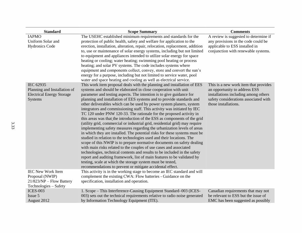
3.3
3
Standard Scope Summary Comments
IAPMO
Uniform Solar and
Hydronics Code
The USEHC established minimum requirements and standards for the
protection of public health, safety and welfare for application to the
erection, installation, alteration, repair, relocation, replacement, addition
to, use or maintenance of solar energy systems, including but not limited
to equipment and appliances intended to utilize solar energy for space
heating or cooling; water heating; swimming pool heating or process
heating; and solar PV systems. The code includes systems where
equipment and components collect, convey, store and convert the sun’s
energy for a purpose, including but not limited to service water, pool
water and space heating and cooling as well as electrical service.
A review is suggested to determine if
any provisions in the code could be
applicable to ESS installed in
conjunction with renewable systems.
IEC 62935
Planning and Installation of
Electrical Energy Storage
Systems
This work item proposal deals with the planning and installation of EES
systems and should be elaborated in close cooperation with unit
parameter and testing aspects. The intention is to give guidance for
planning and installation of EES systems and to provide standards and
other deliverables which can be used by power system planers, system
integrators and commissioning staff. This activity was initiated by IEC
TC 120 under PNW 120-33. The rationale for the proposed activity in
this areas was that the introduction of the ESS as components of the grid
(utility grid, commercial or industrial grid, residential grid) may require
implementing safety measures regarding the urbanization levels of areas
in which they are installed. The potential risks for these systems must be
studied in relation to the technologies used and their locations. The
scope of this NWIP is to prepare normative documents on safety dealing
with main risks related to the couples of use cases and associated
technologies, technical contents and results to be included in the safety
report and auditing framework, list of main features to be validated by
testing, scale at which the storage system must be tested,
recommendations to prevent or mitigate accidental effect.
This is a new work item that provides
an opportunity to address ESS
installations including among others
safety considerations associated with
those installations.
IEC New Work Item
Proposal (NWIP)
21/823/NP – Flow Battery
Technologies – Safety
This activity is in the working stage to become an IEC standard and will
complement the existing CWA: Flow batteries - Guidance on the
specification, installation and operation.
ICES-003
Issue 5
August 2012
1. Scope – This Interference-Causing Equipment Standard–003 (ICES-
003) sets out the technical requirements relative to radio noise generated
by Information Technology Equipment (ITE).
Canadian requirements that may not
be relevant to ESS but the issue of
EMC has been suggested as possibly

3.3
4
Standard Scope Summary Comments
Spectrum Management and
Telecommunications
Interference-Causing
Equipment Standard
2. Purpose and Applications – 2.1 ITE is defined as devices or systems
that use digital techniques for purposes such as data processing and
computation. ITE is any unintentional radiator (device or system) that
generates and/or uses timing signals or pulses having a rate of at least 9
kHz and employs digital techniques for purposes such as computation,
display, data processing and storage, and control. ITE is designated
Category II Equipment, meaning that a Technical Acceptability
Certificate (TAC) or equipment certification is not required. ITE that is
subject to ICES-003 is approved through Self-Declaration of
Compliance (SDoC) by the manufacturer, importer or distributor of ITE,
which will ensure compliance with all technical requirements prescribed
by ICES-003 and the results compiled into a test report. That report shall
clearly state which test method was used to determine compliance. The
methods of measurement are set out in the standards incorporated by
reference in ICES-003 specified in section 3.
affecting ESS or other systems
connected to ESS and is being
included here for consideration.
IEEE 519-1992
Recommended Practices and
Requirements for Harmonic
Control in Electrical Power
Systems
The guide applies to all types of static power converters used in
industrial and commercial power systems. The problems involved in the
harmonic control and reactive power compensation of such converters
are addressed, and an application guide is provided. Limits of
disturbances to the AC power distribution system that affect other
equipment and communications are recommended.
Should be reviewed for relevance to
ESS.
IEEE 1145-1999
Recommended Practice for
Installation and Maintenance
of Nickel-Cadmium
Batteries for Photovoltaic
(PV) Systems
The document provides safety precautions, installation design
considerations, and procedures for receiving, storing, commissioning,
and maintaining pocket- and fiber-plate nickel-cadmium storage
batteries for PV power systems. Disposal and recycling
recommendations are also discussed. This recommended practice applies
to all PV power systems, regardless of size or application that contain
nickel-cadmium battery storage subsystems.
Note applicability to commissioning
and O&M.
IEEE 1187-2013
Recommended Practice for
Installation Design and
Installation of Valve-
Regulated Lead-Acid
Batteries for Stationary
Applications
The document provides guidance for the installation and installation
design of VRLA batteries. This recommended practice is intended for all
standby stationary installations. However, specific applications, such as
emergency lighting units and semi-portable equipment, may have other
appropriate practices and are beyond the scope of this recommended
practice. Alternative energy applications are not covered.

3.3
5
Standard Scope Summary Comments
IEEE P2030.2.1
Working Group (WG),
Guide for Design,
Operation, Maintenance of
Battery Energy Storage
Systems, both Stationary and
Mobile, and Applications
Integrated with Electric
Power Systems
(SASB/SCC21/WGBESS)
The document provides alternative approaches and practices for design,
operation, maintenance, integration and interoperability, including
distributed resources interconnection, of stationary or mobile battery
energy storage systems (BESS) with the EPS at customer facilities,
electricity distribution facilities or bulk transmission electricity facilities.
This document addresses BESS and applications conformance to the
IEEE 1547 series requirements for distributed resources interconnection,
implementing IEEE 2030 smart grid interoperability reference model
(SGIRM) guidance, and builds upon the IEEE 1547, IEEE 2030, and
relevant IEEE PV standards and IEEE standards for batteries.
This standard is intended to be used by BESS designers, operators,
system integrators, and equipment manufacturers. It provides an
introduction of engineering concerns of BESS, identifies key technical
parameters, engineering approaches and application practices
requirements of BESS, and its operation and maintenance (O&M). It
addresses not only electric power concerns but also the directly related
communications and information technology concerns for BESS and
applications integrated with EPSes. Implementation of this guide will
assist in the standardization of BESS applications.
ICC
International Building Code
(IBC)
The provisions of this code shall apply to the construction, alteration,
relocation, enlargement, replacement, repair, equipment, use and
occupancy, location, maintenance, removal and demolition of every
building or structure or any appurtenances connected or attached to such
buildings or structures. Exception: Detached one- and two-family
dwellings and multiple single-family dwellings (townhouses) not more
than three stories above grade plane in height with a separate means of
egress and their accessory structures shall comply with the International
Residential Code.
The IBC should be reviewed as it
relates to the installation in, on or
around buildings and safety issues
addressed in the code, including but
not limited to chemical storage,
designation of ESS related areas as
hazardous, limitations on ESS
locations, fire separation, egress, fire
suppression and smoke control.
ICC
International Fire Code
(IFC)
This code establishes regulations affecting or relating to structures,
processes, premises and safeguards regarding:
1. The hazard of fire and explosion arising from the storage, handling or
use of structures, materials or devices;
2. Conditions hazardous to life, property or public welfare in the
occupancy of structures or premises;
The IFC should be reviewed as it
relates to the installation in, on or
around buildings and safety issues
addressed in the code including but
not limited to fire department and
first responder access, egress, fire
suppression and smoke control.

3.3
6
Standard Scope Summary Comments
3. Fire hazards in the structure or on the premises from occupancy or
operation;
4. Matters related to the construction, extension, repair, alteration or
removal of fire suppression or alarm systems; and
5. Conditions affecting the safety of fire fighters and emergency
responders during emergency operations.
ICC
International Mechanical
Code (IMC)
The IMC regulates the design, installation, maintenance, alteration and
inspection of mechanical systems that are permanently installed and
utilized to provide control of environmental conditions and related
processes within buildings. It also regulates those mechanical systems,
system components, equipment and appliances specifically addressed
herein. The installation of fuel-gas distribution piping and equipment,
fuel gas-fired appliances and fuel gas-fired appliance venting systems
shall be regulated by the International Fuel Gas Code.
Exception: Detached one- and two-family dwellings and multiple single-
family dwellings (townhouses) not more than three stories high with
separate means of egress and their accessory structures shall comply
with the International Residential Code.
Where an ESS is installed indoors
provisions in the IMC related to
ventilation and exhaust and
separation of the room where the ESS
is located from other portions of the
building could apply and should be
reviewed.
ICC
International Plumbing Code
(IPC)
The IPC applies to the erection, installation, alteration, repairs,
relocation, replacement, addition to, use or maintenance of plumbing
systems within this jurisdiction. This code shall also regulate
nonflammable medical gas, inhalation anesthetic, vacuum piping,
nonmedical oxygen systems and sanitary and condensate vacuum
collection systems. The installation of fuel-gas distribution piping and
equipment, fuel-gas-fired water heaters and water heater venting
systems shall be regulated by the International Fuel Gas Code.
Exception: Detached one- and two-family dwellings and multiple single-
family dwellings (townhouses) not more than three stories high with
separate means of egress and their accessory structures shall comply
with the International Residential Code.
Where an ESS involves fluids and
fluid piping the provisions of the IPC
could apply to the piping, floor drains
and based on the fluids conveyed how
leaks and discharges are to be
captured and removed.
ICC
International Wildland
Urban-Interface Code
The provisions of the IWUCl apply to the construction, alteration,
movement, repair, maintenance and use of any building, structure or
premises within the wildland urban-interface areas in this jurisdiction.
Where an ESS is to be installed in an
area that is subject to wildfires, it may
be appropriate to consider how such
installations should be protected or

3.3
7
Standard Scope Summary Comments
Buildings or conditions in existence at the time of the adoption of this
code are allowed to have their use or occupancy continued, if such
condition, use or occupancy was legal at the time of the adoption of this
code, provided such continued use does not constitute a distinct danger
to life or property.
Buildings or structures moved into or within the jurisdiction shall
comply with the provisions of this code for new buildings or structures.
located to minimize damage to them
from wild fires.
IEEE 80
Guide for Safety in AC
Substation Grounding
The guide covers outdoor ac substations, either conventional or gas-
insulated. Distribution, transmission, and generating plant substations
are also included. With proper caution, the methods described herein are
also applicable to indoor portions of such substations, or to sub-stations
that are wholly indoors. No attempt is made to cover the grounding
problems peculiar to DC substations. A quantitative analysis of the
effects of lightning surges is also beyond the scope of this guide.
While not applicable directly to an
ESS the document might be
applicable if an ESS were a
component of a substation and in that
case might benefit from a review for
possibly addressing ESS in the future.
This guide could serve to develop
ESS grounding, although if such a
decision were made and considering
other similar situations such as IEEE
979 on fire protection, instead of
separate issue-focused standards, it
would be appropriate to consider a
singular standard for ESS
installations (grounding) and other
relevant issues such as fire protection.
IEEE 100
The Authoritative Dictionary
of IEEE Standards Terms
Seventh Edition
While not just applicable to ESS
installations but also components and
entire systems, a review of this
document should be undertaken to
determine any needed revisions or
additions to address ESS technology.
IEEE 693
Recommended Practice for
Seismic Design of
Substations
The document provides seismic design recommendations for
substations, including qualification of each equipment type. Design
recommendations consist of seismic criteria, qualification methods and
levels, structural capacities, performance requirements for equipment
operation, installation methods, and documentation.
Note this would apply to systems as
well as installations but while not
applicable to ESS it could apply to
situations where the ESS is a
component of a substation. See

3.3
8
Standard Scope Summary Comments
additional discussion under IEEE 80,
100 and 979 regarding applicability
of substation standards to an ESS or
use of these standards to craft a
standard covering all issues, such as
seismic, for ESS.
IEEE 937
Recommended Practice for
Installation and Maintenance
of Lead-Acid Batteries for
PV Systems
The standard covers design considerations and procedures for storage,
location, mounting, ventilation, assembly, and maintenance of lead-acid
secondary batteries for PV power systems are provided. Safety
precautions and instrumentation considerations are also included. Even
though general recommended practices are covered, battery
manufacturers may provide specific instructions for battery installation
and maintenance.
IEEE 979
Guide for Substation Fire
Protection
The original guide (1994) was developed to identify substation fire
protection practices that generally have been accepted by industry. The
new edition includes changes in industry practices for substation fire
protection. New clauses on fire hazard assessment and pre-fire planning
have been added. The purpose of the original guide (1994) was to give
design guidance, fire hazard assessment, and pre-fire planning in the
area of fire protection to substation engineers. Existing fire protection
standards, guides, and so on that may aid in the design of specific
substations or substation components are listed in Annex F. the new
edition revision updates that guidance.
While not applicable directly to an
ESS the document might be
applicable if an ESS were a
component of a substation and in that
case might benefit from a review for
possibly addressing ESS in the future.
This guide might serve as a model for
the development of a similar guide
for ESS fire protection.
IEEE 1184
Guide for Batteries for
Uninterruptible Power
Supply Systems
The guide discusses various battery systems so that the user can make
informed decisions on selection, installation design, installation,
maintenance, and testing of stationary standby batteries used in UPS
systems.
This guide divides the available
technologies into the following three
main categories: VLA, VRLA and
NiCd batteries.
IEEE/ASHRAE 1635-2012
Guide for the Ventilation
and Thermal Management of
Batteries for Stationary
Applications
The document discusses VLA, VRLA, and NiCd stationary battery
installations and is intended to serve as a bridge between the electrical
designer and the heating, ventilation, and air-conditioning (HVAC)
designer. Ventilation of stationary battery installations is critical to
maximize battery life while minimizing the hazards associated with
hydrogen production. This guide describes battery operating modes and
the hazards associated with each. It provides the HVAC designer with
the information to provide a cost-effective ventilation solution.
The document should be reviewed for
its applicability to all possible ESS
and where criteria are found in need
of revision or development research
and analysis should be undertaken as
warranted to support revisions. Note
that the identification and conduct of
research and analysis to support

3.3
9
Standard Scope Summary Comments
changing existing standards or
development of new criteria for
existing or new standards apply to
every possible standards development
response to address deployment of
safe ESS.
IEEE 1547
Standard for Interconnecting
Distributed Resources
with Electric Power Systems
The standard establishes criteria and requirements for interconnection of
distributed resources (DR) with electric power systems (EPS). It
provides a uniform standard for interconnection of distributed resources
with electric power systems. It also provides requirements relevant to
the performance, operation, testing, safety considerations, and
maintenance of the interconnection.
The U.S. Federal Energy Policy Act of 2005 calls for state commissions
to consider certain standards for electric utilities. Under Section 1254 of
the Act: “Interconnection services shall be offered based upon the
standards developed by the Institute of Electrical and Electronics
Engineers: IEEE Standard 1547 for Interconnecting Distributed
Resources with Electric Power Systems, as they may be amended from
time to time.”
IEEE 1547 was first published in 2003, reaffirmed in 2008, and
Amendment 1 published in 2014 as an outgrowth of the IEEE-hosted
SCC21 May 2012 Workshop. More than 80 industry participants
collaborated in the IEEE-hosted SCC21 December 2013 workshop, and
recommended a revised title, scope, and purpose to launch an IEEE
SCC21 project and working group to complete a full revision of the
IEEE 1547 standard before 2018, but preferably sooner.
Would apply to ESS that are
interconnected with EPS and as a
result may need to be reviewed to
determine if any changes are needed
to more appropriately address
interconnection with ESS.
IEEE C2-2012 - 2012
National Electrical Safety
Code (NESC)
This Code covers basic provisions for safeguarding of persons from
hazards arising from the installation, operation, or maintenance of
conductors and equipment in electric supply stations and overhead and
underground electric supply and communication lines. It also includes
work rules for the construction, maintenance, and operation of electric
supply and communication lines and equipment. The standard is
applicable to the systems and equipment operated by utilities, or similar
systems and equipment, of an industrial establishment or complex under
As with the NEC (NFPA 70) below
this document should be reviewed to
identify any areas where it should be
revised to address ESS safety. That
may also include a reference to
standards applicable to ESS
components or entire ESS. Note the
NESC also addresses operation and

3.4
0
Standard Scope Summary Comments
the control of qualified persons. This standard consists of the
introduction, definitions, grounding rules, list of referenced and
bibliographic documents, and Parts 1, 2, 3, and 4 of the 2012 Edition of
the NESC.
maintenance, a topic covered in
Section 3.4 below but for simplicity
the NESC is included here.
NFPA 15-2012
Standard for Water Spray
Fixed Systems for Fire
Protection
The standard helps ensure effective fire control, extinguishment,
prevention, or exposure protection through requirements for the design,
installation, and system acceptance testing of water spray fixed systems
for fire protection. It also contains requirements for the periodic testing
and maintenance of ultra high-speed water spray fixed systems.
The standard should be reviewed for
possible application to ESS. If not
applicable or in need of revision,
changes should be pursued. Based on
further analysis and research,
development of additional criteria for
ESS fire protection may be warranted
where application of this standard
might be inappropriate based on ESS
technology.
NFPA 70-2014
National Electrical Code
(NEC)
Adopted in all 50 states, NEC is the benchmark for safe electrical
design, installation and inspection to protect people and property from
electrical hazards. The NEC addresses the installation of electrical
conductors, equipment and raceways; signaling and communications
conductors, equipment and raceways; and optical fiber cables and
raceways in commercial, residential and industrial occupancies. Article
480 provides electrical installation requirements for all stationary
installations of electrical storage batteries (photo). For batteries in PV
systems, additional requirements of Art 690, Part VIII apply. But
covering a battery system from square one to end of life requires far
more knowledge than what is in Art 480 (see SIDEBAR: Beyond Article
480). 2014 NEC includes a subsection on battery and cell terminations.
A meeting was held on June 3, 2014
of interested parties to initiate work
on possible changes to the NEC that
are due November 7, 2014 (see
Section 6.2 below.)
NFPA 70E-2012
Standard for Electrical
Safety in the Workplace
NFPA 70E requirements for safe work practices to protect personnel by
reducing exposure to major electrical hazards. Originally developed at
Occupational Safety and Health Administration (OSHA)’s request, NFPA
70E helps companies and employees avoid workplace injuries and
fatalities due to shock, electrocution, arc flash and arc blast, and assists in
complying with OSHA 1910 Subpart S and OSHA 1926 Subpart K.
NFPA 400-2013
Hazardous Materials Code
NFPA 400 consolidates fundamental safeguards for the storage, use, and
handling of hazardous materials in all occupancies and facilities. The
Code does not apply to storage or use of hazardous materials for
This document would appear to apply
to energy storage systems to the
degree that those systems contained

3.4
1
Standard Scope Summary Comments
individual use on the premises of one- and two-family dwellings. The
Code’s fire and life safety requirements are applicable to a wide range of
substances including but not limited to ammonium nitrate solids and
liquids, corrosive solids and liquids, flammable solids, organic peroxide
formulations, oxidizers, pyrophoric solids and liquids, toxic and highly
toxic solids and liquids, unstable (reactive) solids and liquids, water-
reactive solids and liquids. Compressed gases and cryogenic fluids are
included within the context of NFPA 55.
hazardous materials. As such, the
document could limit where ESS are
located in, on or around buildings and
if so located how they are to be
protected. A review of this document
in that regard is advised and based on
that review revisions to the document
considered, research conducted in
support of those revisions or ESS
installations adjusted accordingly in
conformance with the document.
NFPA 550-2012
Guide to the Fire Safety
Concepts Tree
The guide describes the structure, application and limitations of the Fire
Safety Concepts Tree, which provides an overall structure with which to
analyze the potential impact of fire safety strategies. NFPA 550
examines the interrelation of fire safety features and their effect on
achieving specific fire safety goals and objectives. It identifies tools to
help fire safety practitioners communicate fire safety and protection
concepts and can be used to assist with the analysis of codes or
standards, facilitate the development of performance-based designs,
provide an overall structure with which to analyze potential fire safety
strategy impacts and identify gaps and redundancies in the strategies.
See Section 6.2, below.
NFPA 704-2012
Standard System for the
Identification of the Hazards
of Materials for Emergency
Response
The standard provides criteria for assessing the health, flammability
instability and related hazards presented by short-term, acute exposure to
a material under conditions of fire, spill or similar emergencies. A
number rating system of 0-4 is provided to rate each of the four hazards
on a placard and provides emergency responders with information to
determine immediate actions in an emergency. Tables in the standard
provide criteria for the ratings and placard specifications such as letter
size and arrangement of numbers and colors.
See Section 6.2, below.
NFPA 790-2012
Standard for Competency of
Third-Party Field Evaluation
Bodies
Installed electrical equipment that has not been previously certified,
listed, recognized, or classified undergo a “field evaluation” to ensure
compliance. The standard provides qualifications and competencies for
third parties performing field evaluations and specifies how they are to
be completed. Provisions cover FEB application for recognition; FEB
organization; FEB personnel; appeals, complaints, and disputes;
The standard should be reviewed and
considered for use in addressing the
acceptability of third party agencies
that may undertake a review of ESS
installations for safety.

3.4
2
Standard Scope Summary Comments
application for evaluation; preparation for evaluation; evaluation;
evaluation report; decision to issue an FEB statement of conformity; use
of FEB statement of conformity; and test and measuring equipment.
NFPA 850-2010
Recommended Practice for
Fire Protection for Electric
Generating Plants and High
Voltage DC Converter
Stations
The document outlines fire safety recommendations for gas, oil, coal,
and alternative fuel electric generating plants, including high voltage DC
converter stations and combustion turbine units used for electric
generation. Fire prevention and fire protection recommendations
advance the safety of construction and operating personnel, physical
integrity of plant components, and the continuity of plant operations.
Specific criteria provided include combustion turbines and internal
combustion engines, alternative fuels, wind turbine generating facilities,
solar thermal power generation, and geothermal power plants.
NFPA has formed a task group of
NFPA 850, 851 and 853 to look into
how to address ESS.
NFPA 851-2010
Recommended Practice for
Fire Protection for
Hydroelectric Generating
Plants
The document provides fire prevention and fire protection
recommendations for hydroelectric generating plants to safeguard
personnel, protect physical property, ensure continuity of power
production, and control the impact of fire and firefighting activities on
the environment. NFPA 851 offers guidance for the design, construction,
and operation of hydroelectric facilities. In addition, general plant
design, fire protection systems, identification and protection of hazards,
and development of a fire risk control program are also covered.
Should be reviewed for possible
guidance in addressing fire protection
of ESS installations.
NFPA 853-2010
Standard for the Installation
of Stationary Fuel Cell
Power Systems
The standard provides fire prevention and protection requirements for
safeguarding life and physical property for buildings or facilities that
employ stationary fuel cell systems of all sizes. Criteria cover design,
construction and installation requirements, including general equipment
configuration, siting and interconnections, fuel supplies and storage
arrangements, ventilation, exhaust and fire protection. Specific
provisions for fuel cell power systems 50 kW or less are also included.
See Section 6.4, below.
The NFPA Foundation
(CSR related activity)
The NFPA Foundation is conducting a multi-phase research program to
develop guidance for the protection of lithium-ion batteries in storage (it
is not clear if this is applicable to those used in energy storage
applications or simply the storage of those batteries while awaiting sale
or distribution or both). The first two phases of this project, a hazard
assessment and a large-scale flammability characterization, were
completed in 2013. The latter program provided good information on the
performance of cartoned small format batteries in storage and
Related to installation CSR, the
following research announcement
indicates there is interest in
addressing ESS fire protection
(conducting research may signal a
void in CSR or need to update current
CSR to address new technology).
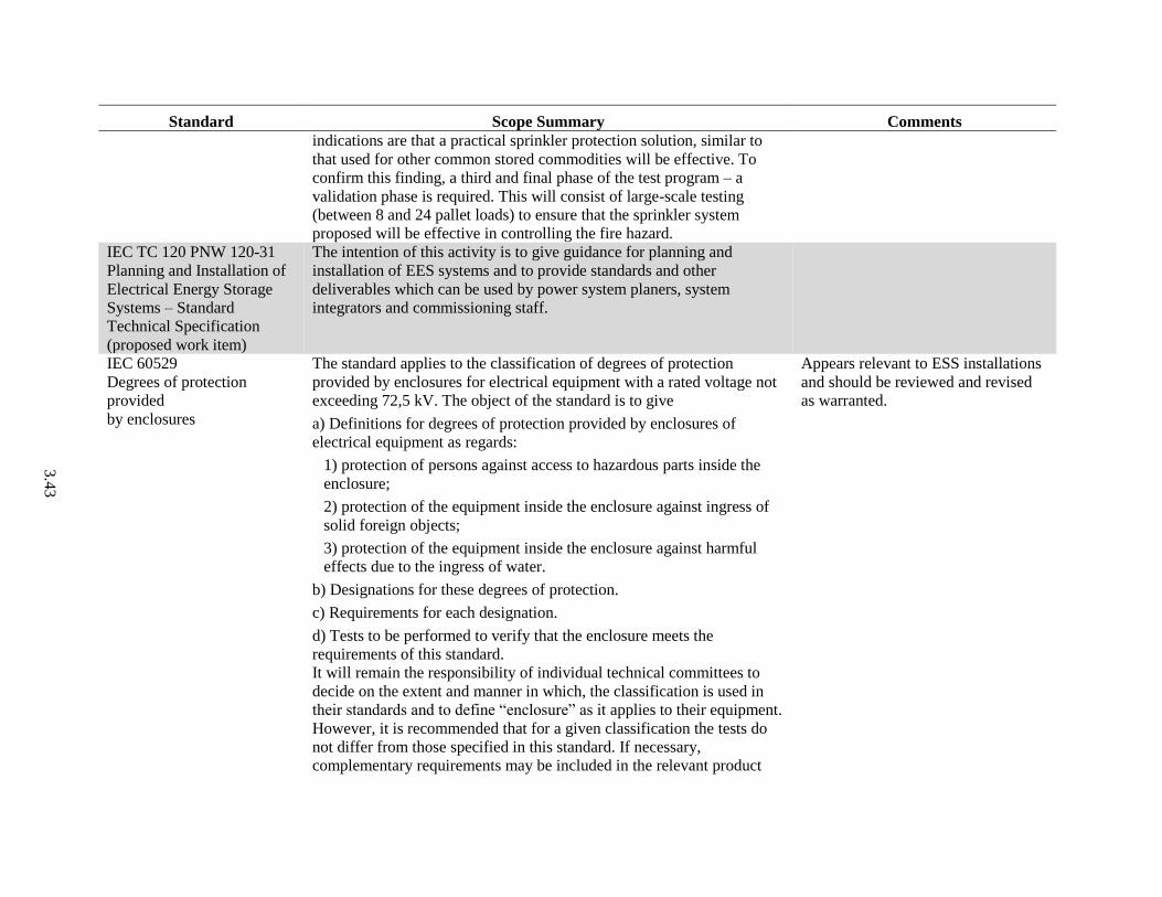
3.4
3
Standard Scope Summary Comments
indications are that a practical sprinkler protection solution, similar to
that used for other common stored commodities will be effective. To
confirm this finding, a third and final phase of the test program – a
validation phase is required. This will consist of large-scale testing
(between 8 and 24 pallet loads) to ensure that the sprinkler system
proposed will be effective in controlling the fire hazard.
IEC TC 120 PNW 120-31
Planning and Installation of
Electrical Energy Storage
Systems – Standard
Technical Specification
(proposed work item)
The intention of this activity is to give guidance for planning and
installation of EES systems and to provide standards and other
deliverables which can be used by power system planers, system
integrators and commissioning staff.
IEC 60529
Degrees of protection
provided
by enclosures
The standard applies to the classification of degrees of protection
provided by enclosures for electrical equipment with a rated voltage not
exceeding 72,5 kV. The object of the standard is to give
a) Definitions for degrees of protection provided by enclosures of
electrical equipment as regards:
1) protection of persons against access to hazardous parts inside the
enclosure;
2) protection of the equipment inside the enclosure against ingress of
solid foreign objects;
3) protection of the equipment inside the enclosure against harmful
effects due to the ingress of water.
b) Designations for these degrees of protection.
c) Requirements for each designation.
d) Tests to be performed to verify that the enclosure meets the
requirements of this standard.
It will remain the responsibility of individual technical committees to
decide on the extent and manner in which, the classification is used in
their standards and to define “enclosure” as it applies to their equipment.
However, it is recommended that for a given classification the tests do
not differ from those specified in this standard. If necessary,
complementary requirements may be included in the relevant product
Appears relevant to ESS installations
and should be reviewed and revised
as warranted.

3.4
4
Standard Scope Summary Comments
standard. A guide for the details to be specified in relevant product
standards is given in annex B.
For a particular type of equipment, a technical committee may specify
different requirements provided that at least the same level of safety is
ensured. This standard deals only with enclosures that are in all other
respects suitable for their intended use as specified in the relevant
product standard and which from the point of view of materials and
workmanship ensure that the claimed degrees of protection are
maintained under the normal conditions of use.
This standard is also applicable to empty enclosures provided that the
general test requirements are met and that the selected degree of
protection is suitable for the type of equipment to be protected.
Measures to protect both the enclosure and the equipment inside the
enclosure against external influences or conditions such as mechanical
impacts, corrosion, corrosive solvents (e.g., cutting liquids), fungus,
vermin, solar radiation, icing, moisture (e.g., produced by condensation),
explosive atmospheres and the protection against contact with hazardous
moving parts external to the enclosure (such as fans), are matters for the
relevant product standard to be protected.
IEC 62485-1 Ed 1
Safety requirements for
secondary batteries and
battery installations – Part 1
General safety information
Should be reviewed for possible
application to ESS and revised as
warranted.
IEC 62485-2
Safety requirements for
secondary batteries and
battery installations. Part 2:
Stationary batteries.
This part of the IEC 62485 applies to stationary secondary batteries and
battery installations with a maximum voltage of DC 1 500 V (nominal)
and describes the principal measures for protections against hazards
generated from: electricity, gas emission, and electrolyte. This
international standard provides requirements on safety aspects
associated with the erection, use, inspection, maintenance and disposal.
Appears identical to IEC 50272-2
IEC 62485-3 Ed 1 Safety
requirements for secondary
batteries and battery
installations – Part 3 traction
This part of IEC 62485 applies to secondary batteries and battery
installations used for electric vehicles (e.g., in electric industrial trucks,
including lift trucks, tow trucks, cleaning machines, automatic guided
vehicles), battery powered locomotives, electric vehicles (e.g., goods
While not applicable to ESS, the
standard may prove to be a resource
in determining provisions needed to
address ESS installation safety.

3.4
5
Standard Scope Summary Comments
batteries vehicles, golf carts, bicycles, wheelchairs) and does not cover the design
of such vehicles. The standard covers lead dioxide-lead (lead-acid),
nickel oxide-cadmium, nickel-oxide-metal hydride and other alkaline
secondary batteries. Safety aspects of secondary lithium batteries in such
applications will be covered in their own appropriate standards. The
nominal voltages are limited to 1 000 V AC and 1 500 V DC,
respectively, and describe the principal measures for protection against
hazards generally from electricity, gas emission and electrolyte. It
provides requirements on safety aspects associated with the installation,
use, inspection, maintenance and disposal of batteries.
IEC 62485-4 Ed 1 Safety
requirements for secondary
batteries and battery
installations – Part 4: VRLA
batteries for use in portable
appliances
While not applicable to ESS, the
standard may prove to be a resource
in determining provisions needed to
address the safety of ESS
installations.
IEC 61434:1996-10-03
Edition 1.0 Secondary cells
and batteries containing
alkaline or other non-acid
electrolytes – Guide to
designation of current in
alkaline secondary cell and
battery standards
Applies to secondary cells and batteries containing alkaline or other non-
acid electrolytes. It proposes a mathematically correct method of current
designation which shall be used in future secondary cell and battery
standards.
IEC/TS 61438:1996-11-28
Edition 1.0 Possible safety
and health hazards in the use
of alkaline secondary cells
and batteries – Guide to
equipment manufacturers
and users
The document outlines the fundamental conditions necessary for the
creation of each hazard. It includes identification and characterization of
the possible hazards inherent in the application, use, and abuse of nickel-
cadmium cells and batteries. It also includes examples for appliance
design which minimizes these hazards. Additionally it presents some
typical but non-exhaustive examples of misuse that may precipitate or
actions which mitigate the hazard.
UL 96A, Installation
Requirements for Lightning
Protection Systems
The document is intended to assist code authorities, designers, and
installers to develop, and install a complete lightning protection system
that can withstand the tremendous power of a lightning strike.
Depending on the type, a strike can exceed 300,000 Amperes, over one
Should be reviewed and considered
as related to protection of ESS
installations from the effects of
lightning.

3.4
6
Standard Scope Summary Comments
gigavolt (one billion volts) and with temperatures as high as 36,000 Deg.
F., or about three times as hot as the surface of the sun. This guide does
not include information on protection of equipment inside a building.
The dissipation of a lightning strike requires correct system design,
installation in accordance with UL 96A, NFPA 780 and all listed
components correctly installed and connected to earth. And common
bonded to the building electrical system in accordance with Article 230,
250, 280, 800 and 810, of the NEC. This installation guide covers
definitions and installations used on virtually all types of structures
designed and built today. The installation must be designed to protect
the entire structure not just a small portion or section of the structure.
3.47
3.4 Codes, Standards and Regulations for Commissioning, Operation or Maintenance of an ESS
Table 3.4 is a listing of CSR applicable to the commissioning, operation or maintenance of an ESS or
which may provide some guidance in addressing the installation of an ESS due to their addressing similar
technologies or issues likely to be relevant in assessing ESS safety. Included are any and all CSR that
clearly apply, may apply or while not directly applicable to ESS may offer some insight or examples that
could be applied in the future to ESS installations. The title and designation of the standard and summary
of the scope are provided along with initial comments relating to further consideration of the standard in
addressing ESS safety. Although the focus of this document is U.S. CSR, some international standards are
included because they are covered in Section 4.0 on ESS approval experiences or were presented in
presentations during the DOE Safety Workshop in February 2014 (Sandia and PNNL 2014; Appendix B).

3.4
8
Table 3.4. Standards for ESS Commissioning, Operation or Maintenance
Standard Scope Summary Comments
ANSI Z535
Safety Alerting Standards
ANSI Z535.1 sets forth the technical definitions, color standards, and color tolerances for the ANSI Z535 uniform safety color
ANSI Z535.2 regulates requirements for the design, application, and use of safety signs in facilities and in the environment through consistent visual layout. Reorganized to best describe the five types of safety signs used in facilities, the 2011 edition of this standard is revised to better harmonize with ANSI Z535.4, ANSI Z535.5, and ANSI Z535.6
ANSI Z535.3 provides general criteria for the design, evaluation, and use of safety symbols to identify and warn against specific hazards and information to avoid personal injury
ANSI Z535.4 delivers specifications for design, application, use, and placement of safety signs and labels on a wide variety of products. A new type of product safety sign, the “safety instruction sign,” was added to join the existing types of signs, hazard alerting signs, and safety notice signs, which were also more clearly defined and named in this edition. The definitions for “accident,” “harm,” and “incident” were refined to more clearly delineate a separation between physical injury and other safety-related issues (e.g., property damage). It was revised to correspond with ANSI Z535.2, ANSI Z535.5, and ANSI Z535.6
ANSI Z535.5 discusses tag and tapes, which are used only until the identified hazard is eliminated or the hazardous operation is completed. The Z535.5-2011 edition was revised to link with ANSI Z535.2, ANSI Z545.4, and ANSI Z535.6. The Safety Instructions Tag was in addition to existing types of signs, hazard alerting tags as well as safety notice tags and barricade tapes, which were more clearly defined and named in this edition. Industries (typically manufacturing and construction) that employ lockout/tagout procedures or have a need to mark an area affected by a temporary hazard will find this standard beneficial.
ANSI Z535.6 provides updated information for manufacturers to promote efficient development of safety messages.
ESS installations will need signage and
safety alert messaging and directions.
Compliance with these standards, as
applicable to ESS, should be
considered. If there is something
uniquely different about ESS when
compared to other items covered by
these standards then revision to one or
more of the standards may be warranted
to ensure anything uniquely needed to
address ESS is covered and the
standards can be referenced and applied
to ESS to foster uniformity in safety
altering messaging.
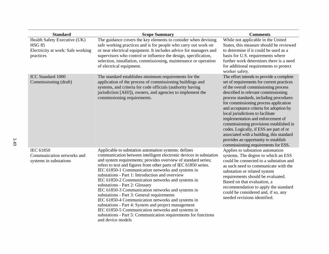
3.4
9
Standard Scope Summary Comments
Health Safety Executive (UK)
HSG 85
Electricity at work: Safe working
practices
The guidance covers the key elements to consider when devising
safe working practices and is for people who carry out work on
or near electrical equipment. It includes advice for managers and
supervisors who control or influence the design, specification,
selection, installation, commissioning, maintenance or operation
of electrical equipment.
While not applicable in the United
States, this measure should be reviewed
to determine if it could be used as a
basis for U.S. requirements where
further work determines there is a need
for additional requirements to protect
worker safety.
ICC Standard 1000
Commissioning (draft)
The standard establishes minimum requirements for the
application of the process of commissioning buildings and
systems, and criteria for code officials (authority having
jurisdiction [AHJ]), owners, and agencies to implement the
commissioning requirements.
The effort intends to provide a complete
set of requirements for current practices
of the overall commissioning process
described in relevant commissioning
process standards, including procedures
for commissioning process application
and acceptance criteria for adoption by
local jurisdictions to facilitate
implementation and enforcement of
commissioning provisions established in
codes. Logically, if ESS are part of or
associated with a building, this standard
provides an opportunity to establish
commissioning requirements for ESS.
IEC 61850
Communication networks and
systems in substations
Applicable to substation automation systems: defines communication between intelligent electronic devices in substation and system requirements; provides overview of standard series; refers to text and figures from other parts of IEC 61850 series. IEC 61850-1 Communication networks and systems in substations - Part 1: Introduction and overview IEC 61850-2 Communication networks and systems in substations - Part 2: Glossary IEC 61850-3 Communication networks and systems in substations - Part 3: General requirements IEC 61850-4 Communication networks and systems in substations - Part 4: System and project management IEC 61850-5 Communication networks and systems in substations - Part 5: Communication requirements for functions and device models
Applies to substation automation
systems. The degree to which an ESS
could be connected to a substation and
as such need to communicate with the
substation or related system
requirements should be evaluated.
Based on that evaluation, a
recommendation to apply the standard
could be considered and, if so, any
needed revisions identified.

3.5
0
Standard Scope Summary Comments
IEC 61850-6 Communication networks and systems for power utility automation - Part 6: Configuration description language for communication in electrical substations related to IEDs IEC 61850-7 Communication networks and systems in substations - Basic communication structure for substation and feeder equipment IEC 61850-7-1: Principles and models IEC 61850-7-2: Abstract communication service interface (ACSI) IEC 61850-7-3: Common Data Classes IEC 61850-7-4: Compatible logical node classes, data classes
IEC 61850-8 Communication networks and systems in substations - Specific Communication Service Mapping (SCSM) IEC 61850-8-1: Mappings to MMS (ISO 9506-1 and ISO 9506-2) and to ISO/IEC 8802-3
IEC 61850-9 Communication networks and systems in substations - Specific Communication Service Mapping (SCSM) IEC 61850-9-1: Sampled values over serial unidirectional multidrop point to point link IEC 61850-9-2: Sampled values over ISO/IEC 8802-3
IEC 61850-10 Communication networks and systems in substations - Part 10: Conformance testing
IEEE 450
Recommended Practice for
Maintenance, Testing, and
Replacement of Vented Lead-
Acid (VLA) Batteries for
Stationary Applications
The document provides recommended maintenance, test
schedules and procedures to optimize the life and performance of
permanently installed VLA storage batteries for standby power
applications. It provides guidance to determine when batteries
should be replaced. This practice is applicable to full-float
stationary applications where a charger maintains the battery and
provides DC loads. However, specific applications such as
emergency lighting units and semi-portable equipment may have
other appropriate practices beyond the scope of this
recommended practice.
Applies to VLA but could serve as a
resource for standards addressing the
same subject by for different ESS
technologies.
IEEE 1106
Recommended Practice for
Installation, Maintenance, Testing
and Replacement of Vented NiCd
Batteries for Stationary Applications
The document provides recommendations for installation design
and for installation, maintenance, and testing procedures to
optimize life and performance of vented NiCd batteries in
stationary standby applications. Also provides guidance for
determining when these batteries should be replaced.
Applies to Ni-Cad batteries but could
serve as a resource for standards
addressing the same subject by for
different ESS technologies.
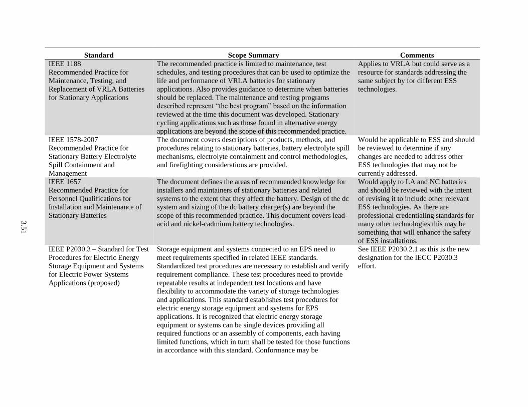
3.5
1
Standard Scope Summary Comments
IEEE 1188
Recommended Practice for
Maintenance, Testing, and
Replacement of VRLA Batteries
for Stationary Applications
The recommended practice is limited to maintenance, test
schedules, and testing procedures that can be used to optimize the
life and performance of VRLA batteries for stationary
applications. Also provides guidance to determine when batteries
should be replaced. The maintenance and testing programs
described represent “the best program” based on the information
reviewed at the time this document was developed. Stationary
cycling applications such as those found in alternative energy
applications are beyond the scope of this recommended practice.
Applies to VRLA but could serve as a
resource for standards addressing the
same subject by for different ESS
technologies.
IEEE 1578-2007
Recommended Practice for
Stationary Battery Electrolyte
Spill Containment and
Management
The document covers descriptions of products, methods, and
procedures relating to stationary batteries, battery electrolyte spill
mechanisms, electrolyte containment and control methodologies,
and firefighting considerations are provided.
Would be applicable to ESS and should
be reviewed to determine if any
changes are needed to address other
ESS technologies that may not be
currently addressed.
IEEE 1657
Recommended Practice for
Personnel Qualifications for
Installation and Maintenance of
Stationary Batteries
The document defines the areas of recommended knowledge for
installers and maintainers of stationary batteries and related
systems to the extent that they affect the battery. Design of the dc
system and sizing of the dc battery charger(s) are beyond the
scope of this recommended practice. This document covers lead-
acid and nickel-cadmium battery technologies.
Would apply to LA and NC batteries
and should be reviewed with the intent
of revising it to include other relevant
ESS technologies. As there are
professional credentialing standards for
many other technologies this may be
something that will enhance the safety
of ESS installations.
IEEE P2030.3 – Standard for Test
Procedures for Electric Energy
Storage Equipment and Systems
for Electric Power Systems
Applications (proposed)
Storage equipment and systems connected to an EPS need to
meet requirements specified in related IEEE standards.
Standardized test procedures are necessary to establish and verify
requirement compliance. These test procedures need to provide
repeatable results at independent test locations and have
flexibility to accommodate the variety of storage technologies
and applications. This standard establishes test procedures for
electric energy storage equipment and systems for EPS
applications. It is recognized that electric energy storage
equipment or systems can be single devices providing all
required functions or an assembly of components, each having
limited functions, which in turn shall be tested for those functions
in accordance with this standard. Conformance may be
See IEEE P2030.2.1 as this is the new
designation for the IECC P2030.3
effort.

3.5
2
Standard Scope Summary Comments
established through combination of type, production, and
commissioning tests. Additionally, requirements on installation
evaluation and periodic tests are included in this standard.
NFPA 921-2014
Guide for Fire and Explosion
Investigations
NFPA 921 sets the bar for scientific-based investigation and
analysis of fire and explosion incidents. Referenced in the field,
training, and court, it is the foremost guide for rendering accurate
opinions as to incident origin, cause, responsibility and prevention
and is intended for use by public sector employees responsible for
fire investigation and private sector professionals who conduct
investigations for insurance companies or litigation purposes. All
aspects of fire and explosion investigation are covered from basic
methodology to collecting evidence to failure analysis. Guidelines
apply to all types of incidents from residential fires and motor
vehicle fires to management of complex investigations such as
high-rise fires and industrial plant explosions.
See section 6.2.
IEC/TR 62060:2001-09-27
Edition 1.0 Secondary cells and
batteries - Monitoring of lead-
acid stationary batteries – User
guide
The document applies to lead-acid vented and valve regulated
batteries, for use in stationary battery applications. The objectives
of this technical report are to assist users in the selection of
methods to obtain sufficient information to indicate the state of
health of an operating stationary lead-acid battery; to achieve this
by describing characteristics that can be electrically measured
and remotely interrogated on a regular basis; to indicate the
sensitivity and reliability of the measured data and to provide the
user with methods of interpretation; and to provide users with
good operating characteristics and general guidelines.
Applies to LA batteries but could serve
as a resource for standards addressing
the same subject by for different ESS
technologies.

3.53
3.5 Codes, Standards and Regulations Relevant to Incident Response Associated with an ESS Installation
Table 3.5 is a listing of CSR applicable to the responding to a safety-related incident associated with an
ESS or which may provide some guidance in addressing an ESS due to their addressing similar
technologies or issues likely to be relevant in assessing ESS safety. Included are any and all CSR that
clearly apply, may apply or while not directly applicable to ESS may offer some insight or examples that
could be applied in the future to ESS installations. The title and designation of the standard and summary
of the scope are provided along with initial comments relating to further consideration of the standard in
addressing ESS safety. Although the focus of this document is U.S. CSR, some international standards are
included because they are covered in Section 4.0 on ESS approval experiences or were presented in
presentations during the DOE Safety Workshop in February 2014 (Sandia and PNNL 2014; Appendix B).

3.5
4
Table 3.5. Standards Relevant to Incident Response Associated with an ESS Installation
Standard Scope Summary Comments
NFPA 472
Standard for Competence of
Responders to Hazardous
Materials/Weapons of Mass
Destruction (WMD) Incidents
The standard identifies the minimum levels of competence required
by responders to emergencies involving hazardous materials/WMD.
This standard applies to any individual or member of any
organization who responds to hazardous materials/WMD incidents.
This standard shall cover competencies for awareness level
personnel, operations level responders, hazardous materials
technicians, incident commanders, hazardous materials safety officers
and other specialist employees. Outside the United States, hazardous
materials might be called dangerous goods (see Annex H). WMD are
known by many different abbreviations and acronyms, including
chemical, biological, radiological, nuclear, explosive (CBRNE),
biological, nuclear, incendiary, chemical, explosive (B-NICE),
chemical, ordinance, biological, radiological agents (COBRA), and
nuclear, biological, chemical (NBC).
While not specifically addressing
ESS the standard may provide
some guidance in development of
similar criteria to cover ESS.
NFPA 921
Guide for Fire and Explosion
Investigations
All aspects of fire and explosion investigation are covered from basic
methodology to collecting evidence to failure analysis. Guidelines
apply to all types of incidents from residential fires and motor vehicle
fires to management of complex investigations such as high-rise fires
and industrial plant explosions.
See Section 6.2.
NFPA 1001
Standard for Fire Fighter
Professional Qualifications
The standard identifies the minimum job performance requirements
(JPRs) for career and volunteer fire fighters whose duties are
primarily structural in nature.
Consider review with respect to
applicability to ESS and, if
warranted, develop appropriate
revisions.
NFPA 1500
Standard for Fire Department
Occupational Safety
The standard contains minimum requirements for a fire service-
related occupational safety and health program.
Consider review with respect to its
applicability to ESS and, if
warranted, develop appropriate
revisions.
NFPA 1600
Standard on Disaster/Emergency
Management and Business
Continuity Programs
The standard establishes a common set of criteria for all hazards
disaster/emergency management and business continuity programs,
hereinafter referred to as “the program.” The emergency management
and business continuity community comprises many different
entities, including the government at distinct levels (e.g., federal,
state/provincial, territorial, tribal, indigenous, and local levels);
business and industry; nongovernmental organizations; and
Consider review with respect to its
applicability to ESS and, if
warranted, develop appropriate
revisions.
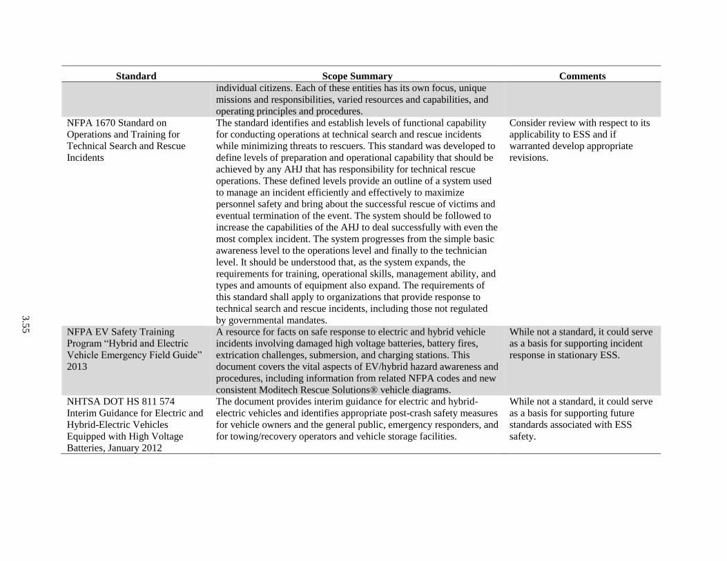
3.5
5
Standard Scope Summary Comments
individual citizens. Each of these entities has its own focus, unique
missions and responsibilities, varied resources and capabilities, and
operating principles and procedures.
NFPA 1670 Standard on
Operations and Training for
Technical Search and Rescue
Incidents
The standard identifies and establish levels of functional capability
for conducting operations at technical search and rescue incidents
while minimizing threats to rescuers. This standard was developed to
define levels of preparation and operational capability that should be
achieved by any AHJ that has responsibility for technical rescue
operations. These defined levels provide an outline of a system used
to manage an incident efficiently and effectively to maximize
personnel safety and bring about the successful rescue of victims and
eventual termination of the event. The system should be followed to
increase the capabilities of the AHJ to deal successfully with even the
most complex incident. The system progresses from the simple basic
awareness level to the operations level and finally to the technician
level. It should be understood that, as the system expands, the
requirements for training, operational skills, management ability, and
types and amounts of equipment also expand. The requirements of
this standard shall apply to organizations that provide response to
technical search and rescue incidents, including those not regulated
by governmental mandates.
Consider review with respect to its
applicability to ESS and if
warranted develop appropriate
revisions.
NFPA EV Safety Training
Program “Hybrid and Electric
Vehicle Emergency Field Guide”
2013
A resource for facts on safe response to electric and hybrid vehicle
incidents involving damaged high voltage batteries, battery fires,
extrication challenges, submersion, and charging stations. This
document covers the vital aspects of EV/hybrid hazard awareness and
procedures, including information from related NFPA codes and new
consistent Moditech Rescue Solutions® vehicle diagrams.
While not a standard, it could serve
as a basis for supporting incident
response in stationary ESS.
NHTSA DOT HS 811 574
Interim Guidance for Electric and
Hybrid-Electric Vehicles
Equipped with High Voltage
Batteries, January 2012
The document provides interim guidance for electric and hybrid-
electric vehicles and identifies appropriate post-crash safety measures
for vehicle owners and the general public, emergency responders, and
for towing/recovery operators and vehicle storage facilities.
While not a standard, it could serve
as a basis for supporting future
standards associated with ESS
safety.

3.56
3.6 Codes, Standards and Regulations for ESS Transportation
Table 3.6 is a listing of CSR applicable to the transport of an ESS or which may provide some guidance
in addressing an ESS due to their addressing similar technologies or issues likely to be relevant in
assessing ESS safety. Included are any and all CSR that clearly apply, may apply or while not directly
applicable to ESS may offer some insight or examples that could be applied in the future to ESS
installations. The title and designation of the standard and summary of the scope are provided along with
initial comments relating to further consideration of the standard in addressing ESS safety. Although the
focus of this document is U.S. CSR, some international standards are included because they are covered
in Section 4.0 on ESS approval experiences or were presented in presentations during the DOE Safety
Workshop in February 2014 (Sandia and PNNL 2014; Appendix B).

3.5
7
Table 3.6. Standards for ESS Transportation
Standard Scope Summary Comments
IEC 62281:2012-12-05 Edition 2.0
Safety of primary and secondary
lithium cells and batteries during
transport.
Specifies test methods and requirements for
primary and secondary (rechargeable) lithium
cells and batteries to ensure their safety during
transport other than for recycling or disposal.
Requirements specified in this standard do not
apply in those cases where special provisions
given in the relevant regulations, listed in 7.3,
provide exemptions. This second edition cancels
and replaces the first edition, published in 2004,
and constitutes a technical revision. This edition
includes the following significant technical
changes with respect to the previous edition:
distinction between small and large cell or
battery by gross mass rather than by lithium
content or watt-hour rating (“nominal” energy);
combination of the no mass loss and no
leakage criteria into one criteria;
extension of an acceptable mass loss of 0.2%
from 5 g to 75 g mass of a cell or battery;
reduction of large batteries to be tested under
tests T 1 to T 5 and T 8 from 4 to 2 samples;
reduction of test samples required for small
battery assemblies (5.2.2);
reduction of the vibration amplitude to 2 g for
large batteries in T-3 vibration test method;
replacement of the impact test by the crush test
for prismatic, pouch, button, and coin cells as
well as cylindrical cells with no more than 20
mm in diameter.
Should be reviewed as applicable to lithium cells
and a determination made if revisions are needed
to better address that type of cell or other types
of cells.
IEC 62540:2009-11-25 Edition 1.0
Radio frequency identification (RFID)
for stationary lead-acid cells and
monoblocs – Tentative requirements
The standard applies to all stationary lead-acid
cells and monobloc batteries for float charge
applications (i.e., permanently connected to a load
and to a DC power supply), in a static location
Should be reviewed as applicable to lithium cells
and a determination made if revisions are needed
to better address that type of cell or other types
of cells.

3.5
8
Standard Scope Summary Comments
(i.e., not generally intended to be moved) and
incorporated into stationary equipment or
installed in battery rooms for use in telecom, UPS,
utility switching, emergency power or similar
applications. These batteries are covered by IEC
60896-11, IEC 60896-21 and IEC 60896-22.
UN 38.3
UN Manual for Tests and Criteria for
Transportation of Dangerous Goods,
Lithium Battery Testing Requirements
The document presents the procedures to be
followed for the classification of lithium metal
and lithium ion cells and batteries (see UN Nos.
3090, 3091, 3480 and 3481, and the applicable
special provisions of Chapter 3.3 of the Model
Regulations).
38.3.2 Scope
38.3.2.1 All cell types shall be subjected to tests
T.1 to T.6 and T.8. All non-rechargeable battery
types, including those composed of previously
tested cells, shall be subjected to tests T.1 to T.5.
All rechargeable battery types, including those
composed of previously tested cells, shall be
subjected to tests
T.1 to T.5 and T.7. In addition, rechargeable
single cell batteries with overcharge protection
shall be subjected to test T.7. A component cell
that is not transported separately from the battery
it is part of needs only to be tested according to
tests T.6 and T.8. A component cell that is
transported separately from the battery shall be
tested as a cell.
Should be reviewed as applicable to lithium cells
and a determination made if revisions are needed
to better address that type of cell or other types
of cells.
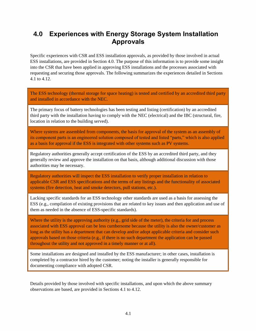
4.1
4.0 Experiences with Energy Storage System Installation Approvals
Specific experiences with CSR and ESS installation approvals, as provided by those involved in actual
ESS installations, are provided in Section 4.0. The purpose of this information is to provide some insight
into the CSR that have been applied in approving ESS installations and the processes associated with
requesting and securing those approvals. The following summarizes the experiences detailed in Sections
4.1 to 4.12.
The ESS technology (thermal storage for space heating) is tested and certified by an accredited third party
and installed in accordance with the NEC.
The primary focus of battery technologies has been testing and listing (certification) by an accredited
third party with the installation having to comply with the NEC (electrical) and the IBC (structural, fire,
location in relation to the building served).
Where systems are assembled from components, the basis for approval of the system as an assembly of
its component parts is an engineered solution composed of tested and listed “parts,” which is also applied
as a basis for approval if the ESS is integrated with other systems such as PV systems.
Regulatory authorities generally accept certification of the ESS by an accredited third party, and they
generally review and approve the installation on that basis, although additional discussion with those
authorities may be necessary.
Regulatory authorities will inspect the ESS installation to verify proper installation in relation to
applicable CSR and ESS specifications and the terms of any listings and the functionality of associated
systems (fire detection, heat and smoke detectors, pull stations, etc.).
Lacking specific standards for an ESS technology other standards are used as a basis for assessing the
ESS (e.g., compilation of existing provisions that are related to key issues and then application and use of
them as needed in the absence of ESS-specific standards).
Where the utility is the approving authority (e.g., grid side of the meter), the criteria for and process
associated with ESS approval can be less cumbersome because the utility is also the owner/customer as
long as the utility has a department that can develop and/or adopt applicable criteria and consider such
approvals based on those criteria (e.g., if there is no such department the application can be passed
throughout the utility and not approved in a timely manner or at all).
Some installations are designed and installed by the ESS manufacturer; in other cases, installation is
completed by a contractor hired by the customer; noting the installer is generally responsible for
documenting compliance with adopted CSR.
Details provided by those involved with specific installations, and upon which the above summary
observations are based, are provided in Sections 4.1 to 4.12.

4.2
4.1 Electric Thermal Storage Systems
The ESS technology (thermal storage for space heating) is safety tested and certified by UL and must be
installed in accordance with national, state and local electric codes. There are two UL standards under
which thermal storage systems are listed: UL 1995, Heating and Cooling Equipment, which are centrally
ducted or supply heat to hydronic systems; and UL 2021, Fixed and Location-Dedicated Electric Room
Heaters, which are direct-connected room heaters. In addition to being tested and listed to these UL
standards, there are requirements covering clearances to combustibles for the installation of the thermal
ESS (the product). Depending on system type, this can range from 2 to 6 inches from surroundings and
combustibles. The NEC also requires at least 36 inches from the electric service panels, which is the front
side of most of the equipment. The dead load of the ESS must also be considered in relation to building
codes, although standard floor surfaces and structures are usually suitable to support the weight of the
systems; however, this is something the contractor should give attention to when applying these thermal
storage systems. 8
4.2 PV Solar and Storage System Combination
The ESS technology involves a solar interconnection where the inverter is shared by the PV system and
ESS (common DC bus with one PV port and one battery port) in a 20-foot shipping container. There are
four projects in NJ/PA/MD, and the main code compliance item has been testing and listing by a third
party (UL). UL 1741 has been used as a basis for testing and certification with IEEE 1547 subsumed
(considered a part of) in that certification. In addition, the installation must follow the NEC (NFPA 70) as
well as the ICC IBC for structural, fire rating and setback from (clearances to) the building. The solar
installations follow an approach used by those enforcing adopted CSR that essentially requires a standard
“engineered solution composed of listed parts.” That approach was used in securing the approval for the
storage system (cells meeting UL 1642, breakers, contactors, fuses, etc.). There is also a professional
engineer review process allowed in some states (e.g., review by an acceptable third party of the proposed
ESS installation), but that review process has not been required in securing approval for these four
projects. All of the component UL certifications are provided to the enforcement authority, which
generally reviews and approves the proposed installation based on those certifications, but occasionally a
30-minute conference with them may be needed at the outset before the on-site inspection at final permit
approval. The enforcement authority also inspects the functionality of the fire detection system installed
with the system (e.g., heat and smoke detectors, pull station and external beacon/siren). 9
4.3 Flow Batteries
There is ambiguity around requirements for energy storage in Australia (AU). Details associated with four
installations in AU are provided below.
A battery system was installed in mid-2013 at the Global Change Institute (GCI), commissioned in
late 2013 and consists of 120kW/288kWh of zinc bromide flow (ZBM) batteries installed in the
basement of the GCI building at University of Queensland. Currently, there are no standards in
Australia for flow batteries. As guidelines, the following Australian Standards were followed: AS
4777 covering grid connection of energy systems, where inverters were installed (installation and
8 Steffes Corporation
9 Solar Grid Storage

4.3
inverter requirements and grid protection) and AS 3000 covering electrical installations (wiring
rules). In terms of grid connection, there is no set or approved process for applying for energy storage
to be connected to the grid, apart from having to gain the utility’s permission. However, it is
completely up to the utility if the system installation received final approval, although there are no set
criteria associated with that review and approval. In this installation, the University of Queensland is
a large utility customer, so they probably would have had some sway, although on the customer side
of the meter, the customer took the responsibility for securing needed approvals. Because there are no
standards for flow batteries in Australia and to protect the company (manufacturer of the system) and
follow good practice, the system manufacturer followed Australian Standards listed below. However,
they had to choose which parts of the standards that applied to them and used the rest as guidelines
for their storage technology. This kind of thinking has influenced a few of their other installations.
– AS2676 – Guide to the installation, maintenance, testing and replacement of secondary batteries
in buildings (related to vented and sealed lead-acid batteries)
– AS3011 – Electrical installations – Secondary batteries installed in buildings (related to vented
and sealed lead-acid batteries)
The Smart Grid, Smart City trial was installed late 2011 to early 2012, commissioned by mid-2012
and is comprised of 60 × 5kW/10kWh ZBM-based ESS installed on the grid side of the meter at
individual residential homes in suburban and rural areas of Newcastle and Scone, Australia.
Currently, there are no standards in Australia for flow batteries. AS 4777 and AS 3000 were used in
this installation as reported above. In terms of grid connection, the utility was involved, and their
criteria and process were the same as reported above. The utility (Ausgrid) was also the customer and
main driver of the entire trial (which covered more than energy storage, as they were testing a number
of other Smart Grid technologies). As such, utility approval was not an issue.
The Advanced Energy Storage trial (AEST) was installed in 2008−2010 and comprised of 29 × 5kW/
20kWh hybrid lead-acid/ZBM ESS installed on the customer side of the meter at individual
residential homes in rural Queensland. The standards and approval situation was identical to the
Smart City trial, although in this case, the utility was Ergon Energy.
One small private customer wanted to connect a residential-scale ZBM-based energy storage system
to the grid in Brisbane, AU. The customer has been trying with little success to get approval from the
local utility for the installation, but each department in the utility noted that it was not their
responsibility. This is most likely because private residential energy storage on-grid is not common,
and other similar applications have not been likely submitted to the utility.
The ESS manufacturer is always approached by the end customer (who is often also the utility), and
gaining approval did not concern the ESS manufacturer but was end customer/utility’s responsibility.
In terms of any alternative methods or materials (performance-based CSR compliance), because the
ESS manufacturer was not largely involved in the approval process, the manufacturer did not have
much experience with the approval process. Most end customers realize that there is a lack of
standards for new battery technologies and understand that the ESS manufacturer cannot always
follow strict guidelines, so they are comfortable with the approach outlined above, wherein what
standards are available that directly or indirectly apply to the ESS are used. In most cases, customers
are not greatly familiar with battery technologies, especially ZBM.10
10
Redflow

4.4
4.4 Hybrid Energy Storage Technology
The Eagle Picher Demonstration Project located in Joplin, MO focused on-peak energy and a UPS for
emergency use (Figure 4.1). The project was commissioned on June 29, 2012 and is a 2 Mwh storage
system, with a 1 Mw rate capability. This system is operating a 480 VDC battery buss voltage, and the
project has three unique battery electro chemistries for energy storage. This demonstration project is
housed in a total of four 40 foot long containers. The demonstration termed the Power Pyramid™ uses
multiple energy inputs and multiple storage tiers within the pyramid to optimize the final solution. Tier 1
can provide a rapid response to short duration load changes while allowing for high cycle count. Tier 2
can provide medium-duration load support for longer duration load fluctuations while being limited to
medium cycle count. Tier 3 can provide long-duration load support for extended load fluctuations while
being limited to low cycle count.
Figure 4.1. Eaglepicher’s Demo Powerpyramid™ Installation
The ATK BESS Project in Promontory, UT (Figure 4.2) is a modular 300 kW/1.2 MWh arrangement that
includes equipment racks, bussing, environmental controls (heating and cooling), fire suppression and
safety components. The system components are portable to the extent that each module can be moved and
replaced with common hand tools and processes. Segregation of controls, power electronics and battery
storage are designed with an emphasis on safety. The project is configured with three battery sub-units
connected to a bi-directional 100 kW inverter. Inverters are 100kW bi-directional that accept 440 VAC,
60Hz, three-phase input. Input conditioning consists of AC/DC rectification and regulation using these
high efficiency inverters. The inverter output contains an inversion and switching section to convert
battery DC outputs to a single/useable AC output. Governed by interfaces between the battery outputs and
the inverter input, switching is necessary to allow battery modeling/selection based on load needs.

4.5
Figure 4.2. ATK BESS System
The Carthage Water & Electric Plant in Carthage, MO is under development (Figure 4.3) and consists of
a Renewable Energy Storage System (RESS) to demonstrate various grid utility applications to include
renewable integration and peak shaving. The RESS operating system will be rated at 100 kW/216 kWh
and will include 20 kW of PV solar and approximately 10 kW of wind turbines. The project will be
competed in spring 2014.
Figure 4.3. CWEP RESS Installation

4.6
An ESS installation in New York City is under development (Figure 4.4) that incorporates EaglePicher
Technologies (EPT)’s PowerPyramid™ into Arista Power’s (OTCBB: ASPW) Power on Demand (PoD)
system for a large multi-story building. This project will provide 200 kW/900 kWh of energy storage. The
system utilizes energy storage to reduce utility costs, specifically demand charges, and allow seamless
enrollment to demand response programs. The system is due to be commissioned in spring 2014.
Figure 4.4. Arista Multi-Story Building, NYC
The National Renewable Energy Laboratory’s (NREL) clean energy user test facility (under
development), consists of a three tiered, 300 kW/386 kWh PowerPyramid™ grid-tied energy storage
system for grid stabilization, microgrid support and on-command power response that will be moved to a
U.S. Department of Defense facility in the future. The tiers of batteries included will be Li-Ion/FePO4,
lead-acid and nickel-iron. The system is designed to be modular so any number of additional tiers could
be added to the system at a later date. This system is will be commissioned in August 2014.
The following are the codes and standards used for the projects described above:
NEC (NFPA 70)
OSHA regulations
UL 1741 (for the inverter)
IEEE 1547 (for the inverter)
New York City building code and fire code (for the Arista building in NYC).
4.5 Large System AC Uninterruptable Power Systems (UPS) and Small System DC UPS
The ESS installed range from 10kVA up to 2000kVA in capacity. This represents the energy that would
be stored internal to the ESS for about 10-20 minutes of backup time. Some large network providers have
battery rooms that would house 10 times the amount of batteries that are stored internal to the ESS
described herein to provide for longer hold up times. The input and output conditions are most
typically 480VAC-480 VAC, but ESS are available for 600VAC I/P down to 208VAC I/P with many

4.7
different O/P voltages from 115/208/220/230/240/480/600. The CSR that have been applied to the ESS
are as follows:
UL1778 “UPS”
UL924 “Emergency Lighting and Power Equipment”
IEC62040 “UPS”
UL 1973 “Batteries for Use in Light Electric Rail (LER) and Stationary Applications”
UL/IEC 60950 “ITE”
IEC62040-5-3 “DC UPS” 380VDC up to 1500VDC
NEC (NFPA 70).
The large system ESS is installed on the customer side of the meter. Figure 4.5 shows the five UPS ESS
on the left side of the photo, with the switch gear for the customer on the right. The ESS manufacturer
leaves the responsibility for the permitting to the customer. These large systems are installed in every
state in the United States. In particular, Phoenix, AZ was noted as having rigorous short circuit arc flash
protection requirements for ESS.11
Figure 4.5. ESS Installation
4.6 Grid Storage Battery
A 1.0 MWHr battery (Kokham battery with S&C invertor) was interconnected on 13.2kv distribution
feeder in a fenced utility enclosure. The only permitting required was from the city for the utility site and
fence construction. As this is a utility asset, only the National Electrical Safety Code (NESC) applies. The
11
Emerson Network Power

4.8
only materials required by those approving the project were to secure approval for the ESS installation for
the physical size of the enclosure around the ESS as part of the construction permit process.12
4.7 Grid-Connected Premise Battery
A 6.0 kWHr battery (Sunverge unit) was installed outdoors in conjunction with utility owned rooftop
solar and interconnected on utility side of the customer meter. There was no permitting, review and
approval process, as this is a utility asset, and only the NESC applies. No materials were required to
secure approval for the ESS installation.
4.8 Customer Connected Premise Battery
A 6.0 kWHr battery (Sunverge unit) was installed indoors in conjunction with rooftop solar and
interconnected on customer side of the utility net meter. The permitting, review and approval process
involved securing an electrical permit from the city in which the ESS was being installed. The basis for
the review and approval of the ESS and electrical permit was the 2011 NEC. There were no other
materials required by those approving the ESS installation (e.g., information, documentation, analysis,
reports, third-party certification, etc.).13
4.9 Tehachapi Storage Project
The Tehachapi Storage Project (TSP) is a 32MWh/8 MW Li-Ion battery with an 8 MW/4 MVAR/9 MVA
bi-directional power conversion system (PCS), along with system level controls/communications
necessary to run eight core tests used to evaluate the capabilities of the Battery Energy Storage System
(BESS) relative to 13 identified operational uses. The TSP system is designed to be capable of a C/4
charge and discharge rate and dynamic reactive power support with a short-term overload of 15 MVAR
(minimum) peak for 4 seconds. The BESS is installed at the monolith substation near Tehachapi, CA. The
BESS output is at 12kV and is connected to the Southern California Edison (SCE) 66kV sub-transmission
system through a 12k/66kV transformer provided by SCE. TSP was installed as an R&D project to
demonstrate grid reliability functions as well as the capability to participate in the energy market and can
be controlled by their respective energy/generation management systems.
SCE specified the following list of codes and standards for the BESS vendor.
IEEE 979, IEEE Guide for Substation Fire Protection
IEEE 100, The New IEEE Standard Dictionary of Electrical and Electronics Terms
IEEE 80, IEEE Guide for Safety in AC Substation Grounding
NEC-2008, NFPA-70 National Electrical Code
ANSI Z535–1994, Product Safety Signs and Labels
IEEE 693-2005, IEEE Recommended Practices for Seismic Design of Substations
ANSI C63.16, American National Standard Guide for Electrostatic Discharge Tests Methodologies
and Criteria for Electronic Equipment
12
Kansas City Power and Light 13
Kansas City Power and Light

4.9
IEEE 139, IEEE Recommended Practice for the Measurement of Radio Frequency Emission from
Industrial, Scientific, and Medical (ISM) Equipment Installed on User’s Premises
IEEE 519, IEEE Recommended Practices and Requirements for Harmonic Control in Electric Power
Systems
IEEE 1547, IEEE Standard for Interconnecting Distributed Resources with Electric Power Systems
IEEE 1547.1, 2005 Standard for Conformance Tests Procedures for Equipment Interconnecting
Distributed Resources with Electric Power Systems (see more ancillary references in IEEE 1547.1
“Normative References” section)
8ANSI C84.1, Electric Power Systems and Equipment—Voltage Ratings (60 Hz)
UL 1741, Inverters, Converters, Controllers and Interconnection System Equipment for Use with
Distributed Energy Resources
NEC Article 480, Storage Batteries
IEEE C2-2007, National Electrical Safety Code 2007 Edition
OSHA 1926.441, Batteries and Battery Charging
IEEE C57.12, IEEE Standard Requirements for Liquid-Immersed Distribution, Power, and
Regulating Transformers
IEEE 987, IEEE Guide for Application of Composite Insulators
IEEE C57.13, IEEE Standard Requirements for Instrument Transformers
IEEE C62.22, IEEE Guide for the Application of Metal-Oxide Surge Arrestors for AC Systems
IEEE C37.90.1, IEEE Standard Surge Withstand Capability (SWC) Tests for Protective Relays and
Relay Systems
IEC 61850, Communication Networks and Systems in Substations
ISO 9000, Quality Management – Parts 1 to 4
ISO 9001, Quality Systems – Model for Quality Assurance in Design, Development, Production,
Installation and Servicing
ISO 9002, Quality Systems – Model for Quality Assurance in Production and Installation
ISO 9003, Quality Systems – Model for Quality Final Inspection and Test
ISO 1459, 1461, Hot-dip Galvanizing
SGIP, Small Generator Interconnection Procedure, FERC Order 2006-B
FERC Order 661, Low voltage ride through (LVRT) – Appendix G.
The ESS vendor was responsible for demonstrating that the BESS met the prescribed standards. SCE
provided quality control oversight. SCE also required the manufacture of a TSP “mini-system”
(30kW/116kWh) to help validate the compliance of the BESS design with relevant standards from the
above list. This mini-system is composed of inverter and battery building-blocks that are used to compile
the full BESS. SCE oversaw factory acceptance testing (FAT) of the mini-system in the supplier’s
factory. After completing the mini-system FAT successfully, the mini-system was delivered to SCE’s
laboratory. Over approximately 6 months of testing, SCE has used the mini-system to thoroughly validate
ESS safety, functionality and performance. Several significant issues (and many minor ones) have already
been identified and resolved due to this mini-system testing. Each of the resolutions implemented have

4.10
also been applied to the BESS; using this scaled-down testing has mitigated safety concerns and will
hopefully reduce down-time for the full BESS.
The BESS is located adjacent to the SCE Monolith 66kV substation. A 6,300 square foot metal building
on a concrete slab was constructed to house the BESS and associated system hardware. The BESS
receives auxiliary power through step-down transformers connected to the monolith 12kV bus. The BESS
performs real and reactive power exchange on the 66kV bus via a series of transformers, and the output is
metered using a CAISO power meter at the 66kV bus interface. The BESS is designed to be an unmanned
facility that will perform specific control algorithms as directed remotely via energy/generation
management systems. Fire alarms are detected both via direct connection to a Remote Terminal Unit
(RTU) and to the system controller. Further, an e-stop (emergency stop) feature has been developed,
whereby the local operation immediately halts bi-directional inverter operation and opens all contactors
on the battery side. Attention has been given in the design to ensure that the e-stop functionality does not
require specific processor based logic or communication requirements.
The TSP Project initiated a CAISO Small Generator Interconnection Agreement (SGIA) and was
included in Queue Cluster 4, along with other new generation within the CAISO-controlled system.
Standard requirements for the CAISO Interconnection Process were followed to allow for market
participation. The facility was constructed within the boundaries of the existing monolith substation,
which alleviated the need for other typical construction related permitting. As noted above, the ESS
vendor was responsible for demonstrating that the BESS met the prescribed standards.
The following list contains some of the materials required to demonstrate compliance with prescribed
standards. The list is not comprehensive but provides many of the significant compliance-related
materials.
Report detailing seismic (earthquake) evaluation
Thermal analyses for BESS heat generation and HVAC capacity
Battery Rack Structural Design drawings
Third-Party Evaluation of Fire Suppression System adequacy
Vendor Report demonstrating effectiveness of FM-200 Fire Suppression System (destructive
demonstration of battery system with application of fire suppression agent)
Heavy Lifting Plan for component installation
Power System Load Flow modeling (for evaluation of Battery impact on the grid). This was used
internally to evaluate the system, and was provided to CAISO as part of the interconnection process
Transformer short-circuit duty requirements (CAISO SGIA submission).
As this was an R&D effort, the SCE project team specification also included additional hardware for
evaluation of the installed system. This hardware included a scaled-down mini-system and an additional
controller for performing Real Time Digital Simulation (RTDS) Hardware In The Loop (HWIL) testing.
The mini-system provided all the main components of the full system to allow lab testing of control
features and verification of operations prior to energizing the full 8 MW BESS. This has proven an
invaluable tool for identifying issues in a controlled setting in advance of commissioning the full system.
Similarly, the HWIL controller in the RTDS environment allowed for placing the controller in a virtual
grid model to evaluate the impact of the BESS on the grid before placing the full system online.

4.11
Additional insight on the installation included extensive safety testing imposed on the vendor of the
battery system to demonstrate the overall safety of the installation and the effectiveness of the fire
suppression system.
4.10 Energy Storage Installations at San Diego Gas & Electric
The following systems have been installed at SDG&E.
Note that all SDG&E installations to date have been outside of buildings. For installations inside
buildings, it is anticipated that the energy storage unit would have to meet UL standards and be tested by
a Nationally Recognized Test Lab. In addition, the installation would have to be approved by the AHJ
following a formal approval process requiring a Plan Check process and electrical inspection.
25 kW/50 kWh, 240V, 1-ph, Lithium-Ion Chem
50 kW/82 kWh , 120/208V, 3-ph, Lithium-Ion
500 kW/1500 kWh, 120/208V, 3-ph, Lithium-Ion
500 kW/1500 kWh, 277/480V, 3-ph, Lithium-Ion.
The following standards were applied to these installations:
ANSI/IEEE C2, National Electrical Safety Code, whenever applicable
IEEE 519, IEEE Recommended Practices and Requirements for Harmonic Control in Electrical
Power Systems
NFPA 704, Standard System for the Identification of the Hazards of Materials for Emergency
Response
ANSI Z535, Product Safety Signs and Labels
ANSI C57/IEEE transformer standards, latest editions, whenever applicable
ANSI C37/IEEE surge withstand capabilities, latest editions, whenever applicable
IEEE P1547-2003, IEEE Standard for Interconnecting Distributed Resources with Electric Power
Systems
IEEE P1547.1, Standard Test Procedures for Equipment Interconnecting Distributed Resources with
Electric Power Systems
UL 1642 and IEC 62133, applicable sections related to battery cell safety, where applicable.
The following environmental requirements were placed on these installations.
The equipment will be installed on the Pacific coast at an elevation below 3300 feet. The environment
may contain salt air, ocean fog, and seismic activity. Extra insulation, material and finishes of above
average durability are required for the equipment to withstand the described environmental effects
The system shall be designed for proper operation without de-rating for an ambient temperature range
of 10F–120F, zero gas/vapor emissions (describe, if exception) and less than 58 decibels (dbA)
measured at the unit (for other noise frequencies provide db specification of unit)
4.12
Systems must be designed to minimize the risk to the environment including land contamination or
disturbance (footprint), water contamination or diversion and air emissions
The seller must provide sufficient information specific to their particular product to facilitate utility
personnel training and communications with emergency response and environmental agencies
Material Safety Data Sheets (MSDS) shall be provided, as applicable.
The following safety-related requirements were placed on the energy storage units and installation.
Units must be compliant with IEEE1547 and UL1642. Systems must be able to protect themselves
from internal failures and utility grid disturbances. As such, systems must be self-protecting for AC or
DC component system failures. In addition, systems must be able to protect themselves from various
types of grid faults and other abnormal conditions on the grid.
Systems must be designed in compliance with applicable safety standards for battery cell
construction, potential exposure to chemicals and cell module or enclosure resistance to hazards such
as ruptures and exposure to fire.
For all systems equipment, the bidder shall provide information on specific safety issues related to the
equipment, including appropriate responses on how to handle batteries in case of an emergency, such
as fires or cell module ruptures.
Systems must be designed such as to minimize risk of injury to the workforce and public during
installation, maintenance and operation.
Systems shall be equipped with meaningful status lights and LED panels to operate the system, and at
minimum provide easy access to mode and AC power (charging or discharging) information. Audible
alarms should be included as necessary to ensure safety, such as chemical leaks.
The following seismic considerations are to be addressed in the installation.
The utility system is located in an active seismic area. The equipment and accessories (including
mounting) shall be designed in accordance with Seismic Zone 4 classification withstand ability.
Container anchoring provisions to the foundations shall be the responsibility of the utility. However,
the seller shall provide physical data (weights, dimensions, centers of gravity, etc.) as required for
foundation and anchoring design.
Compliance with the adopted CSR and specifications is through a review by utility personnel in four
separate departments:
Technology Innovation & Development, Electric Distribution Engineering (Standards), Safety
Compliance and Environmental Operations
Electric Distribution Engineering (Standards)
Safety Compliance
Environmental Operations.

4.13
All ESS installations are done in accordance with the following utility developed manuals.
Overhead Construction Standards Manual
Underground Construction Standards Manual
Electric Standard Practice Manual.
4.11 Southern California Edison
There are four ESS applications as follows:
LG Residential Energy Storage Units (RESU) consisting of LG automotive grade lithium-ion
batteries, 4kW, 10kWh (AC) system operating at 240/120VAC split phase that incorporate up to 4kW
(DC) PV through a single inverter and also provide backup power, and numerous control strategies
S&C PureWave Community Energy Storage (CES) Unit consisting of Kokam lithium-ion batteries,
25kVA, 50kWh (AC) system operating at 240/120VAC split phase with no PV inputs but also
providing islanding, remote control, and aggregation capabilities
A Princeton Power Systems BESS consisting of Samsung lithium-ion batteries, 100kW, 100kWh
(AC) system operating at 480VAC three-phase that incorporates up to 100kW (DC) PV through
single inverter (48kW installed) and also provides backup (not used), and several control strategies
An A123 distribution battery energy storage system (DBESS) consisting of A123 lithium-ion
“nanophosphate” batteries with Parker bi-directional power inverters, 2MVA, 500kWh, 480V, 53 ft
shipping container, plus 40 ft auxiliary skid with two 1MVA isolation transformers and 30 ft
480/12kV interconnection skid provides real/reactive power dispatch, ramping, and profiles.
A listing of all safety-related CSR that the ESS technology (and its subsystems if available) was designed
to satisfy is shown below for each ESS.
LG RESU: UL 1741, UL 1642, FCC Code of Federal Regulations Sections 15.109 and 15.209, IEEE
Std. C37.90.2-1995, IEEE Std. 1547-2003, IEEE Std. 519-1992, ANSI C84.1, SCE Tariff Rule 21,
ITIC CBEMA Curve, IEEE Std. 802.3 and 802.15.4, NEMA 250-2008
S&C Community Energy Storage Unit: All standards were referenced in American Electric Power’s
Functional Specification for CES Unit Revision 2.2
Princeton Power Systems BESS: Same as RESU in section above.
A123 DBESS: UL 1741, IEEE 519, IEEE 1547, NFPA 70 (2008), NFPA 72 (2007), NFPA 101
(2009), FCC Part 15 Class A, EN55022 Class A
SCE performed in-depth laboratory testing on each of the deployed energy storage units. Laboratory
testing included basic (non-destructive) safety, functional and performance testing.
The RESUs were tested and evaluated for several years prior to deployment while the BESS and CES
each underwent over 6 months of testing. Laboratory testing by SCE identified several safety issues
that were not discovered through the UL testing. As an example, each subsystem must be capable of
fully protecting itself in the event of loss of communication. In addition, available standards did not
4.14
address how to control properly the charging and discharging of battery systems (largely vendor
specific) so laboratory testing along with close manufacturer interaction was the only method to
verify fully the correct operation of redundant safety mechanisms.
Two DBESS units were installed, operated and evaluated for more than 3 years at the Large Energy
Storage Test Apparatus (LESTA), a purpose-built test facility with a dedicated 12 kV circuit and load
banks. LESTA allowed SCE personnel to operate the DBESS units in a controlled environment
without affecting actual customers or loaded distribution circuits. Through this testing, SCE gained
valuable installation, operation, maintenance, repair, troubleshooting and performance information.
Nationally recognized laboratories were used to complete the UL Listing of the RESU and BESS (the
two devices that were installed behind customer meters). DBESS subsystem/component
manufacturers used third-party testing to verify compliance with applicable safety standards.
A description of each ESS installation is as follows:
Fourteen of the LG RESU were installed in customer homes behind their meters. The RESUs were
installed in the garage near the main panel. The systems were protected from vehicle impact by a
large steel brace. Flexible conduit was used to connect the RESU to two new electrical panels: one
feeding the RESU and through the second, the RESU provided power to selected circuits for backup.
Backed-up circuits were removed from the main electrical panel and fed ONLY from the RESU to
allow the RESU to isolate them in the event of a grid outage. The self-contained Smart Meter was
employed as the means to satisfy utility requirements for visible disconnection. PV power from the
rooftop system was brought and combined in the garage near the RESU. This combined voltage
connected directly to the RESU. The RESU communicates via LAN (to a 4G radio) to a RESU server
where all devices are remotely controlled. In addition, the RESU utilizes ZigBee communication to
get site demand and energy information from the Smart Meter. This information is used to actively
control the RESU’s charging and discharging powers to modify the load profile of the home.
One S&C Purewave CES was installed next to the street near a residential transformer on the utility
side of meters. Two batteries were installed in a fiberglass enclosure underground with the PCS
installed above them. The CES was installed (electrically) between the transformer and the homes
served. This allows the CES to island the homes in the event of a grid outage. Bollards were required
to protect the CES from vehicle impact. To provide easy isolation in the event of a grid event, a
240VAC bypass switch was also installed near the CES. This switch allows trouble-men to safely and
quickly isolate the CES or otherwise change the electrical configuration of the installation. The CES
is controlled remotely and operates according to specific commands. It is used to shift load on the
street from on-peak to off-peak relieving the circuit. Another operation involves charging the CES
using excess PV generation by the homes and discharging in the evening when the load is highest.
One Princeton Power Systems BESS was installed near a parking structure behind a customer meter.
The entire system was contained within an ISO shipping container. A PV array was installed on the
roof of the parking structure and the DC cables connected the PV array to the BESS. The installation
includes visible AC and DC disconnects. The BESS is used to shift electric vehicle charging load
from on to off-peak. In addition, it actively monitors power usage and generation to modify the load
profile of a solar car shade and charging system.
One A123 DBESS container and auxiliary skid was removed from LESTA using heavy forklifts
(cranes could not be used due to the site’s location beneath 220kV transmission lines), transported to

4.15
Irvine via flatbed trailers and temporarily installed at a greenfield site on the University of California
Irvine’s (UCI) campus. Unlike LESTA, which has a purpose-built concrete slab with built-in
trenches, 12kV vault and electrical switchgear, the greenfield site had no existing infrastructure. The
SGSS container and auxiliary skid were placed and anchored directly on grade, with temporary
precast concrete trenches installed between structures. A new 30-ft interconnection skid was also
installed on grade. The interconnection skid is fed by a PME, which is fed from another switch across
the street. The local PME allows the entire site, including interconnected skid, to be disconnected
from the circuit for installation and removal. The site is concealed, and access is controlled by a 10-ft
chain link fence with cloth mesh siding. Because the location is temporary, the DBESS is controlled
manually on site, though remote control options exist. The system is operated in conjunction with
UCI graduate student experiments to examine the circuit-level effect of on/off/inter-peak charging
and discharging with different power levels, durations, and profiles.
A description of the approval process associated with each ESS installation is as follows:
The LG RESUs each required approval from the City of Irvine and SCE. The city reviewed the
electrical connections to and from the system including the installation of the new electrical panels,
the PV array and the reconfiguration of backed-up circuits. Because the RESU was UL Listed, the
city focused on factors outside of the system and did not investigate the internal safety mechanisms.
SCE’s review was also simplified due to the UL Listing. SCE reviewed the capability for export and
the single line to verify anti-islanding compliance. Because the batteries were coupled with the PV
power through one inverter, the home was not eligible for NEM. SCE produced a new
Uncompensated Export Addendum to the Customer Generating Facility Non-Export Agreement to
allow the RESUs to discharge power to the grid but not receive any credit. SCE inspected the
installation and verified anti-islanding at each location.
The S&C CES was installed as a utility asset; thus, no City of Irvine electrical inspection was
conducted. However, the city and the local Irvine Campus Housing Authority were involved with
easement, aesthetic and vehicle protection concerns. Within SCE, pilot standards for the CES and
CES Bypass switch were produced to ensure trouble-men are appropriately trained. SCE performed
electrical analysis of the installation including flicker and voltage sag for all customers served by the
CES. SCE also performed structural analysis of the underground enclosure containing the batteries.
The Princeton Power Systems BESS was installed on the University of California at Irvine’s campus;
thus, the University performed all electrical, structural and aesthetic review and approval. The BESS
inverter is also UL listed; thus, the review process focused on the external components. The BESS
incorporates a stand-alone fire suppression system. This was disclosed to the University, but no
external communication was provided. The University inspected the system after installation.
The A123 DBESS was installed as a utility asset, so no municipal electrical inspection was necessary.
However, the site and construction were permitted through the City of Irvine and UCI. The site is
subject to a 1-year license from UCI, after which the system will be removed and the site restored to
its previous state.

4.16
The following CSR and approval documentation were employed in the review and approval of the ESS
installations:
The LG RESU was supported by the UL 1741 Listing (not compliance, but full third-party certified
listing) for the entire RESU system (including batteries, charger, inverter and controls) and was
crucial to obtain approval from both the city and SCE. SCE also required verification that the anti-
islanding performance compiled with Rule 21. However, UL 1741 (based on IEEE 1547) is
significantly stricter than Rule 21. An electrical diagram, plot plan, UL letter of certification for the
RESU unit, RESU single line (internal components), operational ranges for each of the inputs and
outputs (AC and DC), nominal power of the system (battery and PV separately) and expected annual
energy production of the PV were provided.
As a utility device, compliance with IEEE 1547 was required for the S&C CES Unit. Anti-islanding
was verified. SCE performed significant laboratory testing to verify safety of the system in a variety
of grid events, loss of communication and other situations. An electrical diagram, physical layout,
rated power (real and reactive), rated energy, islanding power quality and capabilities, operational
ranges for the inputs and outputs, the SCE laboratory test report, installation documentation,
operational procedures and emergency procedures were provided.
The Princeton Power Systems BESS was supported by the UL 1741 Listing for the BESS inverter and
UL 1642 listing for the BESS battery cells were required for installation and interconnection of the
BESS. These certifications were necessary for University approval. An electrical diagram, plot plan,
UL letter of certification for the inverter, UL certification for batteries, BESS single line (internal
components), operational ranges for each of the inputs and outputs (AC and DC), nominal power of
the system (battery and PV separately) and annual PV energy production were provided.
4.12 Portland General Electric
A project of the scope of the Salem Smart Power Center involves engineering of literally every discipline.
One of the primary concerns with the installation was fire safety. They designed their own fire
suppression system that loops a specially designed polymer tubing throughout the battery stacks. A point
source of heat in contact with the tubing causes the tubing to burst at that point and releases fire
suppressant at the location of the heat source.
Some engineers are internal and some are outside consultants; each being responsible for compliance with
those codes and safety standards that fall within their discipline. The project was subject to design criteria
as required in the NEC and NESC. Also, there were required documented inspections by authoritative
regulators and third parties during construction, installation and start up. The project has been in
compliance with all requirements and in several instances, especially as it relates to fire detection and
suppression as noted above have exceeded conventional methods. They also engaged the local fire
department in training to prepare the first responders to respond to any fire at the facility. In addition, the
project was subjected to an internal audit program.
They also had to deal with standard construction concerns not directly related to the battery facility,
which resulted in some re-grading of the property. They also applied the state building code.

5.1
5.0 Performance-based Review and Approval
Generally, CSR tend to be prescriptive in nature, although there can be performance-related provisions
contained within them. Prescriptive criteria direct exactly the acceptable means and methods to be used in
achieving some objective. Examples of prescriptive criteria include the following:
Install 2 by 4 in. framing at 16 in. on center
The surface of the vent shall be at least 18 in. from combustible materials
The floor shall be 12 in. above the base flood elevation
The room shall be provided with at least 15 cfm of ventilation per person
The means of egress shall be at least 36 in. in clear width
Performance criteria establish an objective but do not prescribe the means and methods to achieve that
objective. Examples of performance criteria based on the above examples are:
The wall shall be designed to withstand the anticipated design loads
The temperature on materials surrounding the vent shall be limited to 120°F
The floor shall be elevated so it will not be covered by flood water
The occupants of the room shall have sufficient ventilation to provide for acceptable indoor air
quality
The corridor width shall be sufficient to allow all occupants to get out of the building in an
emergency.
The above examples are from codes covering building construction. Similar examples exist in standards
for equipment and products where prescriptions for how to construct something and desired performance
outcomes are established. Testing confirms that the outcomes desired for specific metrics are realized
without regard for the means employed to secure those outcomes. A review of plans and specifications
and the actual installation validates compliance with any prescriptive criteria. Most equipment and
product standards contain both prescriptive criteria focused on the construction of the subject and then
performance criteria to assess the performance of the subject against specific objectives. This would be
the case for CSR covering ESS components and an ESS “product.” Most CSR that would cover the
installation, commissioning and other aspects associated with installation of an ESS also tend to be
prescriptive in nature, but also generally provide a performance path to document and validate
compliance with the CSR. If CSR that contain criteria that specifically address how to determine the
acceptability of an ESS installation are not available, then as discussed in Section 1.0, there may be no
way to document readily and uniformly that what is proposed is safe or secure the necessary approvals for
and acceptance of the ESS.
Where a technology is mature, CSR will exist that cover the design and construction of the technology
and its component parts if any as well as its installation, commissioning, operation, repair and even
demolition. When satisfied, CSR serve as a basis to document and validate the acceptability of the
technology with respect to topics such as safety covered in CSR. With respect to ESS components or an
ESS “product,” an accredited and approved third-party agency need only evaluate and test them against
applicable standards, assess the results and based on that assessment indicate whether the criteria were

5.2
satisfied or desired metrics achieved. A component or system so assessed and meeting the applicable
standards is then considered listed and labeled. With respect to ESS installation, that assessment is done
by the AHJ or designee using the CSR adopted as the basis for approval. Those CSR will generally
include a reference to and reliance on standards covering the ESS components and the entire ESS.
As covered in Section 3.0:
For ESS components (e.g., batteries, inverters, relays, wire, etc.) covered in Section 3.1, some
standards may exist and others may be under development or simply not available yet (e.g., new
standards are needed).
In the case of standards applicable to an ESS “produce” covered in Section 3.2, appropriate standards
would be comprised of a combination of the component standards by reference and then additional
criteria for how to assemble the components and what performance criteria the ESS was expected to
satisfy would be provided. An alternative in treating the entire ESS as an assembly the acceptability
of the components could be addressed if standards to test and evaluate the resultant assembly of the
components as an ESS “product” were available.
With respect to an ESS installation and its interconnection to other systems as well as the
interrelationship with the built environment (its surroundings) as covered in Section 3.3, CSR may
exist, may be under development or not available yet. Where relevant and ESS-specific CSR do not
exist, existing criteria in CSR can be applied as the basis for an assessment of an ESS by the entity
seeking approval of the ESS. That information combined with how the AHJ views the CSR they have
adopted and the ESS proposed may be a sufficient basis for considering and approving what is
proposed. In other instances, authorities responsible for approval of an ESS installation may not be
inclined to approve the installation until their CSR “catch up” with the technology and provide
specifics upon which they can validate the safety of an ESS installation.
It is important to note that the above items are additive. That is standards are needed to assess the safety
and acceptability of components of an ESS and the ESS “product.” Then CSR are needed to address the
safe installation, application, commissioning, operation, repair/renovation and even de-commissioning of
the ESS.
Until standards are available for use in validating (e.g., testing, listing and certification) the safety of ESS
components and their assembly as an ESS “product” and CSR are available that specifically address how
an ESS is to be installed, commissioned, operated and interconnected with other systems and interact with
its surroundings, there will be challenges associated with securing approval to install and use ESS. In
addition as repairs and renovations or alterations to an existing ESS installation are undertaken the issue
of safety and compliance with CSR will have to be revisited. The challenges in securing the necessary
approvals to deploy safe ESS can be due to the lack of specific criteria in CSR upon which to evaluate an
ESS for safety and approve the installation of the ESS. To ensure that new technologies can be
considered, CSR have an alternative approval path that can be used as a basis for documenting and
validating safe ESS until CSR can be updated and enhanced to provide specific criteria for all ESS
technologies and possible applications. That path provides a basis for documenting and validating
compliance with CSR as long as what is proposed is shown to be no more hazardous nor less safe than
what is currently allowed in or provided for by existing CSR. One challenge is determining the basis for
assessing equivalent performance, especially for new technologies, where there are few similar
technologies and criteria may not be available upon which to base that assessment. Another is securing

5.3
the involvement of an accredited third party testing and certification agency that can conduct the needed
activities and document the safety of the ESS and its intended installation to the relevant AHJs. A more
formidable challenge is that each AHJ may apply this path differently. Even if ESS safety is validated by
an accredited third party on the basis of performance equivalency, the lack of a uniform application by
AHJs of the current CSR in determining that basis can result in each ESS installation being validated as
safe on a different basis. This in turn can necessitate the development of different safety documentation
for each installation.
With the information above as a foundation, the following cover three available methods to document the
safety of an ESS and on that basis seek approval for the ESS under current CSR that may not specifically
address the safety of a proposed ESS installation. While AHJs ultimately retain the authority to perform
the activities described in each method they generally rely on information provided by accredited third
parties. Note that utilities are more likely to conduct this work themselves for ESS installations they will
own and operate than are federal, state or local agencies who are the AHJs associated with the permitting
and approval of ESS installations on the customer side of the meter.
5.1 Unlisted ESS Components or Entire Systems
The acceptability of the ESS “product” or components of an ESS, where there are no applicable or
available standards, can be secured through the application and use of NFPA 791 covered in Section 3.2.
This standard provides a methodology for evaluating and accepting unlabeled electrical equipment (e.g.,
untested and labeled as meeting available and applicable standards) for compliance with the intended
safety associated with nationally recognized standards and other requirements imposed by the AHJ.
Where an ESS component or ESS “product” is tested and labeled as meeting applicable nationally
recognized standards, which are generally adopted by reference as part of CSR that would apply to an
ESS installation, then that associated labeling speaks to the acceptability of the ESS or ESS component.
Where not labeled, because of a choice by the manufacturer or because standards do not yet exist upon
which to assess the safety of the ESS component of ESS “product,” the provisions of NFPA 791 provide
guidance to technology proponents in documenting the acceptability of what is proposed and to AHJs in
evaluating what is proposed and considering if and how it should be approved. It is important to note that
the application of NFPA 791 would likely be different for each ESS manufacturer and for those seeking
to install the ESS as well as each AHJ. As such, while providing a basis for approval, the application and
use of NFPA 791 is more likely to be unique for each ESS and each ESS installation. While providing a
short term means to foster deployment of ESS the availability of specific CSR covering the ESS and ESS
installation would eliminate the need to apply NFPA 791.
5.2 Alternative Methods and Materials
Until the provisions in CSR “catch up” to specifically address ESS installations there is little concrete
guidance for ESS manufacturers or users seeking approval of an ESS installation or for AHJs to use in
assessing the safety of the installation. Alternative methods and materials provisions in CSR provide a
path to documenting or verifying compliance with existing CSR on the basis that what is proposed, while
not specifically addressed in the CSR, is no more hazardous nor less safe than something that is
specifically covered in the CSR. Where an ESS component or entire ESS is unlisted the application of
NFPA 791 as discussed above should be considered and will be helpful in documenting the safety of the
ESS components and ESS “product.” The provisions associated with alternative methods and materials,
while applicable to an ESS component or entire ESS, are more apt to be applied in securing approval for

5.4
the intended installation of the ESS, even if it is listed. This is because, whether listed or unlisted, CSR
also cover how the installation of an ESS in relation to its surroundings is deemed to be safe.
The specifics from the ICC International Green Construction Code (IgCC) are provided below and are
representative of similar language in other CSR covering alternative methods and materials.
SECTION 105
APPROVAL
105.1 General. This code is not intended to prevent the use of any material, method of construction,
design, system, or innovative approach not specifically prescribed herein, provided that such
construction, design, system or innovative approach has been approved by the code official as
meeting the intent of this code and all other applicable laws, codes and ordinances.
105.2 Approved materials and equipment. Materials, equipment, devices and innovative approaches
approved by the code official shall be constructed, installed and maintained in accordance with such
approval.
105.2.1 Used materials, products and equipment. The use of used materials, products and equipment
that meet the requirements of this code for new materials is permitted. Used equipment and devices
shall be permitted to be reused subject to the approval of the code official.
105.3 Modifications. Wherever there are practical difficulties involved in carrying out the provisions
of this code, the code official shall have the authority to grant modifications for individual cases,
upon application of the owner or owner’s representative, provided the code official shall first find
that special individual reason makes the strict letter of this code impractical and that the modification
is in compliance with the intent and purpose of this code and that such modification does not lessen
the minimum requirements of this code. The details of granting modifications shall be recorded and
entered in the files of the department.
105.4 Innovative approaches and alternative materials, design, and methods of construction and
equipment. The provisions of this code are not intended to prevent the installation of any material or
to prohibit any design, innovative approach, or method of construction not specifically prescribed by
this code, provided that any such alternative has been approved. An alternative material, design,
innovative approach or method of construction shall be reviewed and approved where the code
official finds that the proposed design is satisfactory and complies with the intent of the provisions of
this code, and that the material, design, method or work offered is, for the purpose intended, at least
the equivalent of that prescribed in this code. The details of granting the use of alternative materials,
designs, innovative approach and methods of construction shall be recorded and entered in the files
of the department.
105.4.1 Research reports. Supporting data, where necessary to assist in the approval of materials or
assemblies not specifically provided for in this code, shall consist of valid research reports from
approved sources.
105.4.2 Tests. Wherever there is insufficient evidence of compliance with the provisions of this code,
or evidence that a material or method does not conform to the requirements of this code, or in order
to substantiate claims for alternative materials or methods, the code official shall have the authority
to require tests as evidence of compliance to be made at no expense to the jurisdiction. Test methods
shall be as specified in this code or by other recognized test standards. In the absence of recognized

5.5
and accepted test methods, the code official shall approve the testing procedures. Tests shall be
performed by an approved agency. Reports of such tests shall be retained by the code official for the
period required for retention of public records.
105.5 Compliance materials. The code official shall be permitted to approve specific computer
software, worksheets, compliance manuals and other similar materials that meet the intent of this
code.
105.6 Approved programs. The code official or other authority having jurisdiction shall be permitted
to deem a national, state or local program to meet or exceed this code. Buildings approved in writing
by such a program shall be considered to be in compliance with this code.
105.6.1 Specific approval. The code official or authority having jurisdiction shall be permitted to
approve programs or compliance tools for a specified application, limited scope or specific locale.
For example, a specific approval shall be permitted to apply to a specific section or chapter of this
code.14
Each entity that has adopted and enforces CSR that contain the above type of provision then provides an
avenue for approval of an ESS installation on the basis of equivalent performance. The burden of proving
equivalent performance (e.g., no more hazardous nor less safe than something specifically provided in the
CSR) is with the technology proponent (manufacturer or entity wishing to use the technology). Unless the
approval authority can provide details of what information they require to document equivalent
performance, the technology proponent will generally have to review the existing CSR being used, which
can tend to be prescriptive in nature, as the equivalency metric as well as other research related to ESS
safety and develop the rationale and documentation of equivalency themselves. While what is developed
by the ESS proponent may be acceptable to one approval authority, it may not be acceptable to others. As
a result, the application of this path to documenting the safety of ESS before updated and more
appropriate CSR are available can differ from one approval authority to the next. Clearly having examples
of how other ESS installations have been approved, as covered in Section 4.0, can serve to augment the
available documentation. This is something each ESS manufacturer might undertake in an effort to
standardize documenting the safety of their ESS and its intended installations until CSR are available that
provide the needed criteria upon which to approve an ESS installation. Where the manufacturer of the
ESS chooses not to pursue activities to document the safety of their ESS, then that responsibility may fall
on those specifying or installing the ESS. Faced with having to take on that responsibility specifiers or
installers of ESS could choose to forgo ESS application and use or select an ESS from a manufacturer that
has addressed this issue.
In most instances, the AHJ enforcing the CSR will not conduct an assessment of equivalency if what is
proposed does not satisfy their CSR requirements but instead rely on the technology proponent (permit
applicant) to provide the necessary documentation. In this case, the documentation is provided using the
provisions in the current CSR as a metric. This can also be accomplished by a third-party on the basis of a
failure modes and effects analysis or other methodology that is focused on the safety related aspects of an
ESS regardless of what may or may not be in CSR. Either way, there are multiple AHJs whose
application of the CSR they have adopted can and will vary. While the ESS proponent can develop their
own documentation and customize it for each particular ESS installation and AHJ, the use of an
accredited third party can simplify the approval process.
14
Text reproduced with permission via email from the ICC, August 2014.

5.6
5.3 Third-party Safety Documentation
The involvement by an accredited third-party in an assessment of an ESS or ESS installation is relevant to
the two paths identified above. Outside those two paths, a third-party independent assessment of ESS
safety can be considered and would include their identification of the issues that would need to be
addressed, the documentation needed that the ESS proponent would have to supply and the preparation of
a report of findings that documented the acceptability of the ESS supported by failure modes and effects
analysis of FMEA (as noted this analysis could also focus on equivalency with the current CSR). An
FMEA will provide a logical assessment and documentation of safety outside the specifics in any CSR.
Where a third party is assessing safety based on equivalency with current CSR they may include the
criteria to be used in their assessment in an acceptance criteria document, pre-standard, protocol or
guideline that serves as a surrogate for CSR that may not be approved and published and that address the
technology. Accredited third-party agencies will perform such assessments and issue reports of findings
that can be provided to AHJs to document ESS safety and used to secure ESS installation approvals until
CSR are revised to specifically address ESS technology. When the specific criteria needed to address ESS
safety exist in the CSR then more traditional means of testing and listing the ESS and its components and
evaluation of an ESS installation can be applied in documenting and validating ESS safety.
Because some ESS installations may be unique and not readily assessed as discussed above third-parties
can also be employed to assess the acceptability of a specific ESS technology installation on site and as
installed. Those third parties would have to be accredited as field evaluation bureaus (FEBs) in order for
the information they provide to be acceptable to AHJs because they are in essence doing what the AHJ is
authorized to do themselves in approving an ESS installation. For instance, FEBs can be assessed and
accredited by the International Accreditation Service (IAS) to conduct evaluations of electrical equipment
based on the International Accreditation Service Accreditation Criteria for Field Evaluation of Unlisted
Electrical Equipment (AC354). The request for these types of evaluations usually comes from a building
department, code enforcement official, fire marshal or similar regulatory body and is primarily to
determine compliance with applicable codes or standards of innovative, one-of-a-kind, limited
production, used or modified products that are not listed or labeled under a full testing, listing or
certification program. Such an evaluation process may be completed at the point of manufacture, interim
points of distribution, in the evaluating organization’s facilities, in situ or a combination of the above.
Similar programs exist to support utilities in assessing grid side technologies. In the United States, those
include the Canadian Standards Association, UL, LLC, Factory Mutual, Intertek Testing Services, ETL
and in Canada include the Electrical Safety Authority (ESA) field evaluation, CSA, Entela, Intertek
Testing Services, the Quality Auditing Institute, and UL of Canada. Information on third parties that have
been ANSI accredited can be found at https://www.ansica.org/wwwversion2/outside/Portfolio.asp.
Organizations meeting IAS FEB accreditation requirements also meet the requirements of the
Recommended Competency Guidelines for Third-Party Field Evaluation Bodies and the Recommended
Practice and Procedure for Unlabeled Electrical Equipment Evaluation. These guidelines and
recommended practices have been developed by the American Council for Electrical Safety and, as such,
these bodies could also be used by ESS proponents to secure necessary ESS technology and installation
approvals.

5.7
Most governmental authorities provide information on the means and methods for securing approvals on a
performance equivalency basis. For instance, details were found for the following jurisdictions by
searching on “alternative methods and materials.”
Laguna Beach City, CA http://lagunabeachcity.net/civicax/filebank/blobdload.aspx?BlobID=5505
Berkeley, CA
http://www.cityofberkeley.info/uploadedFiles/Online_Service_Center/Planning/ApplicationorAlterna
teMaterialsormethodsofconstruction.pdf
Bellevue, WA
http://www.ci.bellevue.wa.us/pdf/Development%20Services/forms_alternatematerials.pdf
Orange County, CA http://www.ocfa.org/_uploads/pdf/guidea01.pdf
Reedy Creek, FL
http://www.rcid.org/Portals/0/Documents/Permitting/Request_for_Alternative_Materials-
Methods.pdf
Clark County, NV
http://www.clarkcountynv.gov/Depts/development_services/Forms/Form_1003.pdf
In summary, a path to securing ESS technology and installation approvals does exist in CSR. That path
can bridge the gap until CSR are updated to provide specific criteria for ESS components, ESS
“products,” and ESS installations. That said, the implementation of this path is up to the entity responsible
for documenting CSR compliance (e.g., component manufacturer, ESS manufacturer, ESS installer, etc.)
based on what AHJs coving the envisioned ESS installations require of that documentation as supporting
ESS safety and CSR compliance. As such, there is a possibility that each entity using these paths may
choose to evaluate equivalent performance on a different basis.
Increased uniformity in assessment and approval of ESS technology can be facilitated through the use of
accredited third parties who would issue reports of findings of equivalency and acceptability for
consideration by AHJs responsible for approving ESS installations. To facilitate the uniformity and
acceptability of those reports of findings, the development of acceptance criteria or a protocol could be
undertaken. Such a document would essentially mirror or contain criteria that most AHJs would develop
on their own and use as a basis for approval under a performance equivalency based compliance path. In
using these provisions, the ESS proponent then has guidance in preparing documentation of CSR
compliance (on the basis of equivalent performance) as does an accredited third party in reviewing that
documentation and issuing a report of findings as to verification of compliance. That report of findings
can then be used by any AHJ in considering the approval of an ESS and conducting the necessary
inspections to validate compliance with their CSR. The basis is that the report of findings documents
equivalent safety and performance to outcomes derived from compliance with the current CSR, and that
the ESS is installed in accordance with those findings.

5.8
Organizations and entities that would develop such criteria and issue such reports include the following:
Federal, state or local AHJs in the enforcement of their CSR using this alternative path to compliance
verification.
Registered design professionals who are licensed to practice in states where an ESS installation is
proposed.
Manufacturers and ESS proponents (although this would be considered first party self-certification
and not generally accepted by AHJs).
Third-party accredited testing and certification agencies.
Note that those acceptance criteria or protocols can form the basis for revisions to existing CSR or
development of new CSR.
It is also important to separate the manner in which utilities would engage in approval of ESS installations
on the basis of safety-related performance for ESS installations on the grid side of the meter. The utility
can follow the performance equivalency path above and rely on information documenting the acceptance
of the ESS on the basis of equivalent performance to the specific CSR. Where the utility does not adopt
those CSR or is not inclined to recognize information provided by third-party agencies, the utility may act
as the AHJ and conduct specific safety testing themselves, develop their own acceptance criteria and
undertake any other activities they feel are needed to detail a basis for ESS safety and validate that a
proposed ESS complies with what the utility has adopted. For instance, as reported above, one utility
required the conduct of destructive testing to validate that the batteries being supplied would not “run-
away” if an incident were to occur.
Ideally, the proponents of ESS technology can agree on the criteria upon which an ESS is considered safe
in conjunction with AHJs on both sides of the meter, thereby fostering uniformity and more timely and
less complicated review and approval of ESS installations in both the short term to assess ESS safety on
the basis of performance equivalency and the long term in formulating new and revising existing CSR.

6.1
6.0 Next Steps
6.1 Identification of Apparent Gaps in Current CSR
Based on the information provided in Sections 4.0 and 5.0 and a closer review of the CSR provided in
Section 3.0, gaps between current and future ESS technology and the CSR will need to be identified. As
discussed in Section 1.2, those gaps could be updating of existing CSR to more appropriately address ESS
technology, removal of unintended barriers in existing CSR to ESS technology or development of new
CSR criteria to facilitate the deployment of safe ESS where current CSR may not provide appropriate
guidance. Once identified the gap will need to be evaluated as to the severity of its impact on safe ESS
deployment and necessary research, analysis and additional work to determine how to fill the gap
identified and conducted. Filling these gaps can occur through future revisions to existing or development
of new CSR. The availability of updated and appropriate CSR will foster the ability to readily test and list
ESS as to their safety for the intended purpose and use, appropriately install ESS to ensure their safety
and foster the ability for those involved with ESS O&M or incident response to address any safety-related
situations that might arise during ESS installation or after the ESS is placed into service.
Work outlined in Sections 6.2 through 6.4 is intended to start to address the identification of gaps using
current CSR and ESS technology as a basis for identifying gaps (i.e., the CSR are the driver). Concurrent
with these activities additional research and analysis and other activities should be undertaken separately
and without CSR criteria as a driving force to identify what constitutes a safe ESS (i.e., the research and
analysis associated with safety as the driver). Those additional research and analysis activities and
identification of gaps that would be focused on safety are intended to be addressed by the DOE ESS
Safety Strategy and the activities outlined therein on CSR undertaken as a part of that strategy.
6.2 Identification of Opportunities to Revise Current CSR During 2014
The following opportunities to revise existing CSR during 2014, or where the bulk of proposal
development would need to occur during 2014, were mentioned during at the DOE ESS safety workshop
in February 2014 (Sandia and PNNL 2014) and are identified in Table 6.1. The information provided
includes an identification of the document, the due date for any changes to be submitted, a summary of
the general thrust of the needed changes, a summary of needed research or analysis to support the change
and identification of any other relevant factors to revising the CSR in question.

6.2
Table 6.1. 2014 CSR Revisions
Document Due Date for Changes Summary of Changes
NFPA 70
National Electrical Code
November 7, 2014 The general thrust of the needed changes is to re-validate that the provisions applicable to
lead-acid batteries remain current and if not update them and then to add similar provisions
covering other battery technologies. A meeting of interested parties lead by NEMA was
conducted June 3, 2014 to discuss this issue. Provisions in the NEC that need to be
reviewed and evaluated for possible revisions were identified and communications were
undertaken to work with an existing industry-lead working group tasked with review of the
entire NEC and provide ESS-related input to their effort (proposed changes and reasons)
for submission to NFPA. That work is ongoing in anticipation of development of proposed
changes to NFPA 70 and their submittal by the deadline as a component of the existing
industry-lead working group.
NFPA 550
Fire Concepts Tree
January 5, 2015 NFPA 550 was reviewed in relation to ESS to determine if any changes were warranted so
that the document could more appropriately cover ESS. The results of that review
indicated that Sections 3.3 and 3.4 (definitions) cover control of heat-energy transfer and a
definition might be needed for ESS in terms of power-energy (e.g., an ESS incident that
includes not only heat-energy but power/electrical capacity). The broader issue is that all
criteria in Chapter 3 could apply to ESS but maybe after a more thorough review of
Chapter 3 it might be appropriate to see if any criteria might apply to ESS uniquely, if any
that are needed are missing and if any need to be revised to apply to ESS.
A further read of NFPA 550 suggests that it is broad enough to apply to ESS following
either the control combustion or control by construction/isolation provisions. Based on the
short time frame for additional review, proposed changes were halted. In addition, the
manner in which the document is written is considered broad and technology non-specific
such that to propose changes specific to ESS might result in work being done at an
unnecessary level of detail in relation to NFPA 550 criteria. In addition it appeared that an
unlisted ESS assessed in accordance with NFPA 791 that is installed in accordance with
NFPA 550 would be acceptable now in documenting a safe ESS and a safe installation of
that ESS on the basis of performance. Additional review work on NFPA 550 could be
undertaken to outline how it could be most appropriately applied to ESS as currently
written and if deemed appropriate based on that further review guidance in applying NFPA
550 to ESS could be prepared and disseminated as a component of the DOE ESS Safety
Strategy. In addition when proposed changes to NFPA 550 are published they should be
reviewed to determine if any have an impact on ESS and appropriate steps taken to
influence any changes that do impact ESS.

6.3
Document Due Date for Changes Summary of Changes
NFPA 704
ID of Material Hazards
July 7, 2014 This document was reviewed in relation to ESS to determine if any changes were
warranted so the document could more appropriately cover ESS. A review of the standard
indicated that nothing should be changed for ESS. The document covers a specific scope
under which an ESS would fall, and it appears that the ESS manufacturers and those
involved in ESS installations will have to know that this standard exists, that it applies to
ESS and commence using it in identifying any hazards with ESS installation.
NFPA 921
Fire and Explosion
Investigations
January 5, 2015 This document was reviewed in relation to ESS to determine if any changes were
warranted so that the document could more appropriately cover ESS. A review of the
document suggests the following:
a. No recommended changes to Chapter 7 on building systems or Chapter 8 on fire
protection systems
b. Chapter 9 on electricity and fire is primarily focused on basic electrical theory and
protective devices, wiring and 120/240 VAC application receptacles and cabling. There
is no mention of storage batteries, energy storage devices or inverters (although DC
circuits are briefly discussed). Perhaps a mention of commercial batteries, UPS and
ESS could be added for general knowledge and understanding.
c. Chapter 13 Safety, Section 13.3.3 covers electrical hazards (at an investigation scene)
and the current wording [live electrical systems] “could come from standby power
systems” might be revised to mention ESS or large (MW) stored energy systems that
remain live after electrical isolation.
d. No recommended changes to Chapter 23 on explosions or Chapter 24 on incendiary
fires.

6.4
6.3 Identification of Opportunities to Revise Current CSR Beyond 2014
The following opportunities exist to revise existing CSR covered in Section 3.0 where proposed changes
to the CSR are due in 2015 in accordance with updating cycles adopted by the SDO. It is important to
note that where existing model codes or standards do not have established deadlines they would be
considered on continuous maintenance and as such revisions could be submitted at any time for
consideration by the committee within the SDO working on revisions to the standard. When approved,
such revisions could be published in the form of addenda to the last edition of the standard and/or
revisions compiled and combined at particular intervals on the order of 3 to 5 years to yield a new edition
of the standard.
Note also that participation in revising current CSR can be realized in ways other than submitting
proposed changes pursuant to established schedules and processes provided by an SDO. Individuals,
organizations or associations representing the interests of the ESS industry can become members of the
SDO committees and through that process engage in development of revisions to a CSR from the
“inside.” This does not necessarily mean that what is proposed would ultimately be included in the CSR
but it does provide a longer term and more robust way to interact in CSR development.
The list below is not all inclusive but contains information on opportunities published by the SDO. It is
intended that after transferal of this document to a web-based database and pursuant to its maintenance in
support of the DOE ESS Safety Strategy that additional opportunities will be identified, information on
them provided and activities to develop changes and foster their adoption outlined and updated over time.
1. ICC International Building (egress, fire safety and general), International Existing Building Code,
International Fuel Gas Code, International Mechanical Code, International Plumbing Code,
International Residential Code (mechanical and plumbing) and International Zoning Code proposed
changes are due January 12, 2015.
2. ICC International Building Code (administrative and structural), International Energy Conservation
Code, International Fire Code, International Residential Code (building) and International Urban
Wildland Interface Code proposed changes are due January 11, 2016.
3. ICC International Green Construction Code proposed changes are due January 9, 2017.
4. NESC IEEE C2 proposed changes to the 2013 edition and committee recommended changes will be
published September 1, 2014 and available for review and comment. The 2017 edition of the NESC
will be published August 1, 2016. While the deadline has passed to submit proposed changes,
participation in the ongoing process associated with the 2017 edition is warranted. Proposed changes
to the 2017 edition that will form the basis for the 2021 edition of the NESC will be due in July 2017
(http://standards.ieee.org/about/nesc/erp/schedule.pdf).
5. NFPA 791 Unlabeled Electrical Equipment. Proposed changes are due to NFPA by July 6, 2015, and
it was agreed at the meeting June 3, 2014 noted above that this document would be reviewed in
relation to ESS to determine if any changes were warranted so the document could more
appropriately cover ESS. That review indicated that Section 3.3.4 should mention storage in the list of

6.5
things provided and that Sections 5.2 to 5.13 could all apply to ESS and are likely acceptable as
written for ESS but there may be other things unique to ESS that might be included. Section 5.4
“Disconnecting Means” could be enhanced by including a reference to ESS to possibly identify on the
disconnecting means that “Live voltage may still be present when the disconnect open.”
6. NFPA 790 Standard for Competency of Third-Party Field Evaluation Bodies. Proposed changes are
due to NFPA by July 6, 2015. Possible changes for consideration might focus on revisions necessary
to ensure such third parties are competent to address ESS safety assessment and evaluation.
7. Other NFPA standards that are referenced in Section 3.0 have due dates that will occur after 2015 and
should be addressed as discussed where they appear in Section 3.0 based on the applicable due date
for proposed in July of years after 2015.
6.4 Identification of Opportunities to Develop New CSR
Opportunities always exist to develop new CSR where no provisions exist to address a particular issue or
where a myriad of provisions may exist in different documents and the combination of those provisions
into one document would prove beneficial. In the case of new provisions for existing CSR such as a new
chapter to the NESC to cover some aspect of ESS, that activity would be addressed as discussed in
Section 6.3. Where there are no CSR criteria and no logical CSR to locate them or where there are a
myriad of different CSR that each address parts of ESS that could be better combined into one document,
then a new CSR initiative could be undertaken.
An example of this is the installation of stationary fuel cell power plants. About 20 years ago as this
technology was being developed and deployed, experiences with installation in relation to existing CSR
indicated that some CSR addressed some aspects of the installation indirectly. That is, they were not
written to apply to fuel cells but were “force fitted” to address fuel cells because nothing else existed.
Rather than attempt to address the myriad of CSR that covered “pieces” of the installation the fuel cell
industry in collaboration with DOE requested made a request to NFPA to initiate a new standards
development committee to write a standard covering the installation of stationary fuel cell power plants.
In addition, the industry with assistance from DOE developed a protocol (pre-standard) on the subject that
was used as a basis for the NFPA standard once NFPA approved the project. The result was the
publication of NFPA 853 Installation of Stationary Fuel Cell Power Plants. This standard continues to be
maintained by NFPA and is referenced in other relevant NFPA standards and ICC model codes. A similar
standard would be advantageous for ESS and work could be undertaken later in 2014 to draft a new
NFPA standard covering installation of ESS following the format of NFPA 853.
It is intended that after transferal of this document to a web-based database and pursuant to its
maintenance in support of the DOE ESS Safety Strategy that opportunities for new CSR will be
identified, described and where warranted pursued.

7.1
7.0 References
ANSI—American National Standards Institute. 2012. Recommended Practice and Procedures for
Unlabeled Electrical Equipment Evaluation, 2012 Edition. National Fire Protection Association (NFPA)
791-2012.
Conover DR. 2014. Overview of Development and Deployment of Codes, Standards and Regulations
Affecting Energy Storage System Safety in the United States. PNNL-23578, Pacific Northwest National
Laboratory, Richland, WA.
DOE—U.S. Department of Energy. 2014. DOE OE Strategy for Energy Storage Safety. In progress.
Sandia—Sandia National Laboratories and PNNL—Pacific Northwest National Laboratory. 2014. DOE
OE Energy Storage Safety Workshop. Alburquerque, NM. February 17−18.

Appendix A
Materials Relevant to Facilitate Review and Approval of ESS Installations

A.1
Appendix A
Materials Relevant to Facilitate Review and Approval of ESS
Installations
This Appendix contains two examples of materials that are considered relevant to facilitating the review
and approval of ESS installations either directly because they apply to ESS or indirectly because while
not applying to ESS they offer some insight into resources available to address the installation and
approval of other related technologies. After transferal of this document to a web-based database and
pursuant to its maintenance in support of the DOE ESS Safety Strategy, it is intended that additional
existing resources can be identified and ideally as additional work on ESS safety is undertaken that
models for documenting and verifying compliance with CSR and ensuring ESS safety can be developed
for consistent and uniform application and use in fostering the acceptance of safe ESS.
County of Santa Clara Inspection Checklist for Rooftop Photovoltaic (PV) Systems
All National Electrical Code (NEC) references are to both the 2008 and 2011 versions unless otherwise noted. All International Residential Code (IRC), International Building
Code (IBC) and International Fire Code (IFC) references are to the 2012 versions unless otherwise noted.
California amendments to the IRC are noted as CRC
Section 1: PV Array Configuration
Module manufacturer, make, model, and number of modules match the approved plans.
(2009 & 2012 IBC 107.4)
PV modules are listed to UL 1703. (NEC 110.3, 690.4 & IBC 1509.7.4 & CRC R908.1.5).
NOTE: AC modules need to be listed to UL 1703 and UL 1741.
DC modules are properly marked and labeled. (NEC 110.3, 690.4(D) & 690.51)
AC modules are properly marked and labeled. (NEC 110.3, 690.4(D) & 690.52)
Modules are attached to the mounting structure according to the manufacturer’s instructions
and the approved plans. (NEC 110.3(B), 2009 & 2012 IBC 107.4 & CRC R908.1.4)
Roof penetrations are flashed and counter-flashed. (2009 & 2012 IBC Chapter 15 & 2012
IRC Chapter 9)
PV modules are in good condition (i.e., no broken glass or cells, no discoloration, frames not
damaged, etc.). (NEC 110.12(B))
Residential one- and two-family dwelling limited to maximum PV system voltage of 600 V.
(NEC 690.7)
Rooftop systems are designed in accordance with the IBC. (2012 IBC 1509.7 & CRC
R908.1)

A.2
Roof access points, paths and clearances need to comply with the IFC. (IFC 605.11.3.1 -
605.11.3.3.3, CRC R331.4.1 through R331.4.2.4)
Section 2: Grounding
A complete grounding electrode system is installed. (NEC 690.47(A) & (B))
Modules are grounded in accordance with manufacturer’s installation instructions using the
supplied hardware or listed equipment specified in the instructions and identified for the
environment, and using the grounding point identified on the module and in the
manufacturer’s instructions. (NEC 690.43 & 110.3(B))
Properly sized equipment grounding conductor is routed with the circuit conductors. (NEC
690.45, 250.134(B) & 300.3(B))
AC and DC grounding electrode conductors are properly connected. Separate electrodes, if
used, are bonded together. (NEC 690.47, 250.50 & 250.58)
Bonding fittings are used on concentric/eccentric knockouts with metal conduits for circuits
over 250 volts. (NEC 250.97) (see also exceptions 1 through 4)
Bonding fittings are used for ferrous metal conduits enclosing grounding electrode
conductors. (NEC 250.64(E))
Section 3: Wire Management
Wires are secured by staples, cable ties, straps, hangers or similar fittings at intervals that
do not exceed 4.5 feet. (NEC 334.30 & 338.12(A)(3))
Wires are secured within 12 inches of each box, cabinet, conduit body or other termination.
(NEC 334.30 & 338.12(A)(3))
Cable closely follows the surface of the building finish or of the running boards. (2011 NEC
690.4(F) & IFC 605.11.2, CRC R331.3) NOTE: see Section 12 below for additional guidance
on routing of conductors for fire fighter safety concerns
Exposed single conductors, where subject to physical damage, are protected. (NEC
230.50(B) & 300.5(D))
Section 4: Conductors
Exposed single conductor wiring is a 90C, wet rated and sunlight resistant type USE-2 or
listed PV wire. (NEC 690.31(B)) If the wiring is in a conduit, it is 90C, wet rated type RHW-2,
THWN-2, or XHHW-2. (NEC 310.15)
Exposed single conductors used for ungrounded (transformerless) systems are listed and
identified as “PV wire.” (NEC 690.35(D)(3)) For other conductor requirements for
ungrounded systems see NEC 690.35(D)
Conductor insulation is rated at 90C to allow for operation at 70C+ near modules. (NEC
310.15)

A.3
Where conductors or cables are installed in conduits exposed to direct sunlight on or above
rooftops, correction factors for ambient temperature adjustments are applied. (2008 NEC 310.15(B)(2)(c) & 2011 NEC 310.15(B)(3)(c))
Grounded conductor is identified white or grey. (NEC 200.6)
Open conductors are secured and protected. (NEC 338.12(A)(3) & 334.30)
Conductors are not in contact with the roof surface. (NEC 334.30)
DC conductors inside a building are in a metal raceway or MC metal-clad cable that complies with 250.118(10), or metal enclosures. (NEC 690.31(E))
If more than one nominal voltage system conductor is installed in the raceway, permanent
identification and labeling is required. (NEC 200.6(D) & 210.5(C))
For underground conductor installations, the burial depth is appropriate and warning tape is
in place. (NEC 300.5(D)(3) & Table 300.5)
Aluminum is not placed in direct contact with concrete. (NEC 250.120(B) & 110.11)
DC source circuit conductors are rated at 1.25 x 1.25 = 156% short-circuit (ISC) current from
modules. NOTE: The module ISC x number of combined strings, if strings are combined.
When DC source circuits (strings) are connected in parallel the short-circuit current
multiplies and PV output conductors from combined strings need to be sized appropriately.
(NEC 690.8(1) & (B)(1))
PV circuit and premises wiring is separated. (NEC 690.4(B))
PV system conductors shall be grouped and identified. (2011 NEC 690.4(B))
Section 5: Overcurrent Protection
Overcurrent devices in the DC circuits are listed for DC operation. (NEC 110.3(A), (B) &
690.9(D))
DC source circuit overcurrent protection devices are rated at 1.25 x 1.25 = 156% short-
circuit (ISC) current from modules. NOTE: The module ISC x number of combined strings, if
strings are combined. When DC source circuits (strings) are connected in parallel the short-
circuit current multiplies DC overcurrent protective devices need to be sized appropriately.
(NEC 690.8(B)(1))
Inverter output circuit overcurrent protection device (point of connection to AC system
breaker) is sized based on the maximum inverter output current x 125%. (NEC 690.8(A)(3)
& 690.8(B)(1))
Overcurrent protection is required for the PV source circuit (modules and parallel connected
modules), PV output circuit (conductors between source circuits and inverter), inverter
output circuit, battery circuit conductors and equipment. (NEC 690.9(A))
Where three or more strings are combined, a listed combiner box (UL1741) is used and
fuses are required. When DC source circuits (strings) are connected in parallel, the current
through a failed circuit can be the sum of the current connected from the other strings,

A.4
therefore special consideration must be taken to ensure the sum of the total number of
strings minus one does not exceed the module manufacturers series fuse rating, or
conductor ampacity. (NEC 110.3(B), 690.9(A)) NOTE: there are a few exceptions where the
module has a higher series fuse rating and a low ISC rating.
When a back-fed breaker is used as a utility interconnection means, the breaker does not
read “line and load.” (2008 NEC 690.64(B)(5) & 2008 & 2011 NEC 110.3(B), 705.12(D)(5))
PV interconnect breaker is located at the opposite end of the buss from the feeder
connection, unless using 100% rated equipment. (2008 NEC 690.64(B)(7), 705.12(D)(7) &
2011 NEC 705.12(D)(7))
Section 6: Electrical Connections
Crimp on terminals are listed and installed using a listed tool specified for use in crimping
those specific crimps. (NEC 110.3(B) & 110.14)
Pressure terminals are listed for the environment and tightened to manufacturer
recommended torque specifications. (NEC 110.11, 110.3(B) & 110.14)
Connectors are listed for the voltage of the system and have appropriate temperature and
ampere ratings. (NEC 110.3(B) & 110.14)
Twist on wire connectors are listed for the environment (i.e. wet, damp, direct burial, etc.)
and installed per manufacturer’s instructions. (NEC 110.11, 110.3(B), 110.14 & 300.5(B))
Power distribution blocks are listed. (NEC 690.4 & 2011 NEC 314.28(E))
Terminals containing more than one conductor are listed for multiple conductors. (NEC
110.14(A) & 110.3(B))
Connectors and terminals used for fine strand conductors are listed for use with such
conductors. (NEC 110.14(A) & 110.3(B))
Connectors that are readily accessible and operating at over 30 volts require a tool for
opening. (NEC 690.33(C))
Module connectors are tight and secure. (NEC 110.3(B) & 110.12)
Wiring and connections of inverters, PV source circuits, battery connections, etc., and all
interconnections are performed by qualified personnel. (2011 NEC 690.4(E))
Section 7: Charge Controllers
Charge controller is listed to UL Standard 1741. (NEC 110.3 & 690.4(D))
Exposed energized terminals are not readily accessible. (NEC 110.27)
Diversion charge controllers that are used as the sole means of regulating charging of
batteries have a second independent means of control to prevent overcharging. (NEC
690.72(B)(1))

A.5
Section 8: Disconnects
Disconnects used in DC circuits are listed for DC operation. (NEC 110.3)
Disconnects are installed for all current carrying conductors of the PV source. (NEC 690.13 -
690.14)
Disconnects are installed for the PV equipment. NOTE: For inverters and other equipment
that are energized from more than one source, the disconnecting means must be grouped
and identified. (NEC 690.15)
Disconnects and overcurrent protection are installed for all ungrounded conductors in
ungrounded (transformerless) PV power systems. (NEC 240.15 & 690.35)
Section 9: Inverters
Inverters are listed to UL 1741. (NEC 690.4(D)) NOTE: grid-tied system inverters need to be
identified for use in interactive power systems.
Point of connection is at a dedicated breaker or disconnect. (2008 NEC 690.64(B)(1),
705.12(D)(1) & 2011 NEC 705.12(D)(1))
Total rating of the overcurrent devices supplying equipment does not exceed 120% of the
equipment rating. (2008 NEC 690.64(B)(2), 705.12(D)(2) & 2011 NEC 705.12(D)(2))
Listed AC and DC disconnects and overcurrent protection are grouped and identified. (NEC
690.15)
No multi-wire branch circuits are installed where single 120-volt inverters are connected to
120/240-volt load centers. (NEC 690.10(C))
The plastic barrier is re-installed between the AC, DC wiring and communication wires.
(NEC 110.3(B) & 110.27)
Section 10: Batteries
Storage batteries for dwellings have the cells connected to operate at less than 50 volts.
(NEC 690.71(B)(1))
Live parts of battery systems for dwellings are guarded to prevent accidental contact by
persons or objects. (NEC 690.71(B)(2))
Flexible battery cables are listed RHW or THW, 2/0 minimum for battery cell connections.
(NEC 690.74) NOTE: welding cables, marine, locomotive (DLO), and automotive cables do
not meet the current Electrical Code requirements. (NEC 110.3(A) & (B))
Flexible battery cables do not leave the battery enclosure. (NEC 690.74 & 400.8)
Flexible, fine strand cables are only be used with terminals, lugs, devices, and connectors
that are listed and marked for such use. (NEC 690.31(F), 690.74, 110.3(B) & 110.14)

A.6
High interrupt, listed, DC rated fuses or circuit breakers are used in battery circuits. The
amps interruption current (AIC) is at least 20,000 amps. (NEC 690.71(C) & 110.9)
Cables to inverters, DC load centers, and/or charge controllers are in a conduit. (NEC
690.31(A) & 690.31(E))
Conduits enter the battery enclosure below the tops of the batteries. NOTE: this is to avoid
accidental ventilation of gases into electrical equipment where sparks may occur. Follow
battery enclosure manufacturer’s instructions for venting and conduit locations. (NEC
110.3(B), 480.9(A) & 480.10)
A disconnect means is provided for all ungrounded conductors derived from a stationary
battery system over 30 volts. (NEC 480.5 & 690.15) NOTE: see NEC 690.71(E) for
additional service disconnecting means requirements for series connected battery circuits.
Area is well ventilated and the batteries are not installed in living areas. (NEC 408.9(A) &
408.10)
Section 11: Signs and Labels
All interior and exterior DC conduit, enclosures, raceways, cable assemblies, junction boxes,
combiner boxes, and disconnects are marked. (IFC 605.11.1, 2011 NEC 690.31(E)(3)&
CRC R331.2)
The markings on the conduits, raceways and cable assemblies are every 10 feet, within one
foot of all turns or bends and within one foot above and below all penetrations of roof/ceiling
assemblies, walls and barriers. (IFC 605.11.1.4 & CRC R331.2.4)
Marking is placed adjacent to the main service disconnect in a location clearly visible from
where the disconnect is operated. (IFC 605.11.1.3 & CRC R331.2.3)
The markings say “WARNING: PHOTOVOLTAIC POWER SOURCE” and have 3/8 inch (9.5
mm) minimum-sized white letters on a red background. The signs are made of reflective
weather resistant material. Self-adhesive signs are available from suppliers. (IFC
605.11.1.1, 605.11.1.2, 2011 NEC 690.4(E)(3)& CRC R331.2.1-R331.2.2)
Where PV circuits are embedded in built-up, laminate, or membrane roofing materials in roof
areas not covered by PV modules and associated equipment, the location of circuits shall be
clearly marked. (2011 NEC 690.4(F))
Labels are phenolic where exposed to sunlight. Labels required on conduit are permanent,
weather resistant and suitable for the environment. Labels have a red background with white
lettering. The following labels are required as applicable:

A.7
Table: Signage Requirements for PV systems
Code Section Location of Label Text
NEC 690.5(C) Utility-interactive inverter & battery enclosure
WARNING: ELECTRIC SHOCK HAZARD IF A GROUND FAULT IS INDICATED, NORMALLY GROUNDED CONDUCTORS MAY BE UNGROUNDED AND ENERGIZED
NEC 690.35(F) All enclosures with ungrounded circuits or devices which are energized and may be exposed during service
WARNING: ELECTRIC SHOCK HAZARD. THE DC CONDUCTORS OF THIS PV SYSTEM ARE UNGROUNDED AND MAY BE ENERGIZED.
NEC 690.14(C)(1) On main service when DC wiring is run through the building and DC disconnect is located other than at the main service
DC DISCONNECT IS LOCATED….
NEC 690.14(C)(2) On the AC and DC disconnects PV SYSTEM DISCONNECT
NEC 690.53 On the DC disconnects OPERATING CURRENT ___ OPERATING VOLTAGE ___ MAXIMUM SYSTEM VOLTAGE ___ SHORT-CIRCUIT CURRENT ___
NEC 690.54 At interactive points of interconnection, usually the main service
RATED AC OUTPUT CURRENT ___ AMPS NORMAL OPERATING AC VOLTAGE ___ VOLTS
NEC 690.56(B)/ 690.14(D)(4), 705.10 2011 NEC 690.4(H)
At the electrical service and at the PV inverter if not at the same location
A directory providing the location of the service disconnecting means and the PV system disconnecting means
NEC 690.17 On the DC disconnect and on any equipment that stays energized in the off position from the PV supply
WARNING! ELECTRIC SHOCK HAZARD. DO NOT TOUCH TERMINALS. TERMINALS ON BOTH LINE AND LOAD SIDES MAY BE ENERGIZED IN THE OPEN POSITION.
NEC 690.64(B)(7) Inverter output overcurrent protective device (OCPD)
WARNING: INVERTER OUTPUT CONNECTION DO NOT RELOCATE THIS OVERCURRENT DEVICE.
Common Utility Requirement
At the main electrical service when a supply side tap is used
CAUTION! SUPPLY SIDE TAP. OPEN AND LOCK AC PV DISCONNECT BEFORE REMOVING METER.
NEC 690.55 Battery enclosure MAXIMUM OPERATING VOLTAGE, EQUALIZATION VOLTAGE POLARITY OF GROUNDED CONDUCTORS

A.8
Code Section Location of Label Text
When approved by the AHJ through NEC load calculations. NOTE: this is for a reduction of the existing main breaker to facilitate the added PV OCPD. There are no exceptions to 690.64 (B)(2) and 705.12 (D)(2) for the sum of OCPDs exceeding 120% of bus rating, even based on calculations. The main breaker may not be reduced below minimum requirements of NEC 230.79.
Main electric service MAXIMUM MAIN BREAKER SIZE: XXX AMPS
IFC 605.11.1.4 On conduit, raceways, and enclosures, mark every 10 feet, at turns, above/below penetrations
WARNING: PV POWER SOURCE
Section 12: Fire Safety
Rooftop mounted PV panels and modules have the proper fire classification rating. (IBC
1509.7.2& CRC R908.1.2)
Rooftop DC Conduits are located as close as possible to the ridge or hip or valley and from
the hip or valley as directly as possible to an outside wall to reduce trip hazards and
maximize ventilation opportunities. (IFC 605.11.2& CRC R331.3)
Conduit runs between sub-arrays and to DC combiner boxes are installed in a manner that
minimizes total amount of conduit on the roof by taking the shortest path from the array to
the DC combiner box. (IFC 605.11.2& CRC R331.3)
DC Combiner Boxes are located so that conduit runs are minimized in the pathways
between arrays. (IFC 605.11.2& CRC 331.3)
DC wiring in enclosed spaces in buildings is installed in metallic conduit or raceways.
Conduit runs along the bottom of load bearing members. (IFC 605.11.2 & 2011 NEC
690.4(F)& CRC R331.3)
DC wiring methods shall not be installed within 25cm (10”) of the roof decking or sheathing
except where directly below the roof surface covered by the PV modules and associated
equipment. (2011 NEC 690.31(E)(1))
All roofs have an access point that does not place ground ladders over openings such as
windows or doors, are located at strong points of building construction, and in locations

A.9
where the access point does not conflict with overhead obstructions such as tree limbs,
wires, or signs. (IFC 605.11.3.1& CRC R331.3)
Roofs with slopes greater than 2:12 have solar panel layouts that meet the following criteria:
(some exceptions apply, see diagrams in IFC)
o Hip Roofs: Panels/modules are located so that there is a 3-foot wide clear access
pathway from the eave to the ridge on each roof slope where panels/modules are
located. (IFC 605.11.3.2.1& CRC R331.4.2.1)
o Hips and Valleys: If panels/modules are placed on both sides of a hip or valley they are
located no closer than 18 inches to a hip or valley. If the panels are located on only one
side of a hip or valley that is of equal length, then the panels can be placed directly
adjacent to the hip or valley. (IFC 605.11.3.2.3& CRC R 331.4.2.3)
o Single Ridges: Panels/modules are located so that there are two 3-foot wide access
pathways from the eave to the ridge on each roof slope where there are panels/modules
installed. (IFC 605.11.3.2.2& CRC R331.4.2.2)
o Ridges: Panels/modules are located no higher than 3 feet from the top of the ridge in
order to allow for fire department smoke ventilation operations. (IFC 605.11.3.2.4& CRC
R331.4.2.4)
o Access pathways are located at a structurally sound location capable of supporting the
load of fire fighters accessing the roof. (IFC 605.11.3.2.1& CRC R331.4.2.1)

A.10
DHHS (NIOSH) Publication Number 2004-101
Control of Hazardous Energy Sources
Self-Inspection Checklist
Optional Information
Name of school:
Date of inspection:
Career-Technical program/course/room:
Signature of inspector:
Guidelines
This checklist covers regulations issued by the U.S. Department of Labor, Occupational Safety
and Health Administration (OSHA) as a general industry standard under 29 CFR 1910.147.
Another name for control of hazardous energy sources is lockout/tagout. It covers the servicing
and maintenance of machines and equipment in which the unexpected energization or startup of
the machines or equipment, or release of stored energy could cause injury. The regulations cited
apply only to private employers and their employees, unless adopted by a State agency and
applied to other groups such as public employees. A “yes” answer to a question indicates that
this portion of the inspection complies with the OSHA or EPA standard or with a nonregulatory
recommendation.
General Energy Control
1. Does the program require that all hazardous energy sources be isolated, locked or tagged,
and otherwise disabled before anyone performs any activity where the unexpected
energization, startup, or release of stored energy could occur and cause injury? [29 CFR
1910.147(c)(1)]
2. Have procedures been developed, documented, and implemented for the control of
hazardous energy when working with such equipment? [29 CFR 1910.147(c)(4)]
3. Do the procedures clearly outline the scope, purpose, responsibility, authorization, rules,
and techniques to be applied to the control of hazardous energy, and measures to enforce
compliance? [29 CFR 1910.147(c)(4)(ii)]
4. Do procedures exist for shutting down, isolating, blocking, and securing (locks and tags)
energy? [29 CFR 1910.147(c)(4)(ii)(B)]

A.11
5. Do procedures exist and is someone assigned responsibility for removing and transferring
locks and tags? [29 CFR 1910.147(c)(4)(ii)(C)]
6. Do requirements exist for testing a machine or equipment to determine and verify the
effectiveness of lockout/tagout and other energy control measures? [29 CFR
1910.147(c)(4)(ii)(D)]
Protective Materials and Hardware
7. Are locks, tags, chains, adapter pins, or other hardware available for securing or blocking
energy sources? [29 CFR 1910.147(c)(5)(i)]
8. Are these devices durable and substantial? [29 CFR 1910.147(c)(5)(ii)(A)]
9. Are these devices standardized in either color, shape, size, or format? [29 CFR
1910.147(c)(5)(ii)(B)]
10. Do these devices have a provision for identifying the person applying the device? [29 CFR
1910.147(c)(5)(ii)(D)]
11. Do tagout devices or danger tags warn against hazardous conditions if the equipment is re-
energized? [29 CFR 1910.147(c)(5)(iii)]
Note: Acceptable wording includes Do Not Open, Do Not Start, Do Not Close, and Do Not
Energize.
Inspection
12. Are inspections conducted at least annually by an authorized person (other than the ones
using the energy control procedures) to ensure control procedures are being implemented?
[29 CFR 1910.147(c)(6)(i)(A)]
13. Is each inspection certified by identifying the machine or equipment on which the energy
control procedure was being used, the date of the inspection, the people included in the
inspection, and the person performing the inspection? [29 CFR 1910.147(c)(6)(ii)]
Training and Communication
14. Is training provided and documented to ensure that (a) the purpose and function of the
energy control procedures are understood, and (b) the knowledge and skills required for the
safe application and removal of energy controls are acquired? [29 CFR 1910.147(c)(7)(i)]
15. Is this training repeated periodically when changes or deviations occur in the energy
control procedure? [29 CFR 1910.147(c)(7)(iii)
Energy-Isolating Devices
16. Are all energy-isolating devices operated only by authorized persons or under the direct
supervision of an authorized person? [29 CFR 1910.147(c)(8)]

A.12
Notification of Employees
17. Are all employees notified of the application and removal of lockout and tagout controls
whenever such controls directly affect their work activities? [29 CFR 1910.147(c)(9)]
Application of Control
18. Does the application of energy control follow the sequence listed below? [29 CFR
1910.147(d)]
Machine or equipment shutdown by authorized personnel
Machine or equipment isolation: all energy-isolating devices that are needed shall be
located and operated in a manner that isolates the machine or equipment from the
energy source(s).
Lockout and tagout device application:
– Lockout devices shall be affixed in a manner that will hold the energy-isolating
device in a safe or off position.
– Tagout devices shall be affixed in a manner that clearly indicates that the operation
or movement of energy isolating devices from the safe or off position is prohibited.
– If a tag cannot be affixed directly to the energy isolating device, the tag shall be
located as close as safely possible to the device, in a position that will be
immediately obvious to anyone operating the device.
Stored energy: following the application of lockout and tagout devices, all hazardous,
stored, or residual energy shall be relieved, disconnected, restrained, or otherwise
rendered safe.
Verification of isolation: before starting work on the isolated equipment or process, an
authorized person must verify that isolation and de-energization of the machine or
equipment has been accomplished.
19. Has the work area been inspected before the removal of lockout and tagout devices? [29
CFR 1910.147(e)(1)]
20. Has the lockout and tagout device been removed by the person who put it on? [29 CFR
1910.147(e)(3)]
Note: This rule has some limited exceptions.
21. Are outside servicing personnel informed of the lockout and tagout procedures before
equipment is serviced? [29 CFR 1910.147(f)(2)]

Appendix B
CSR-Related Presentation Material
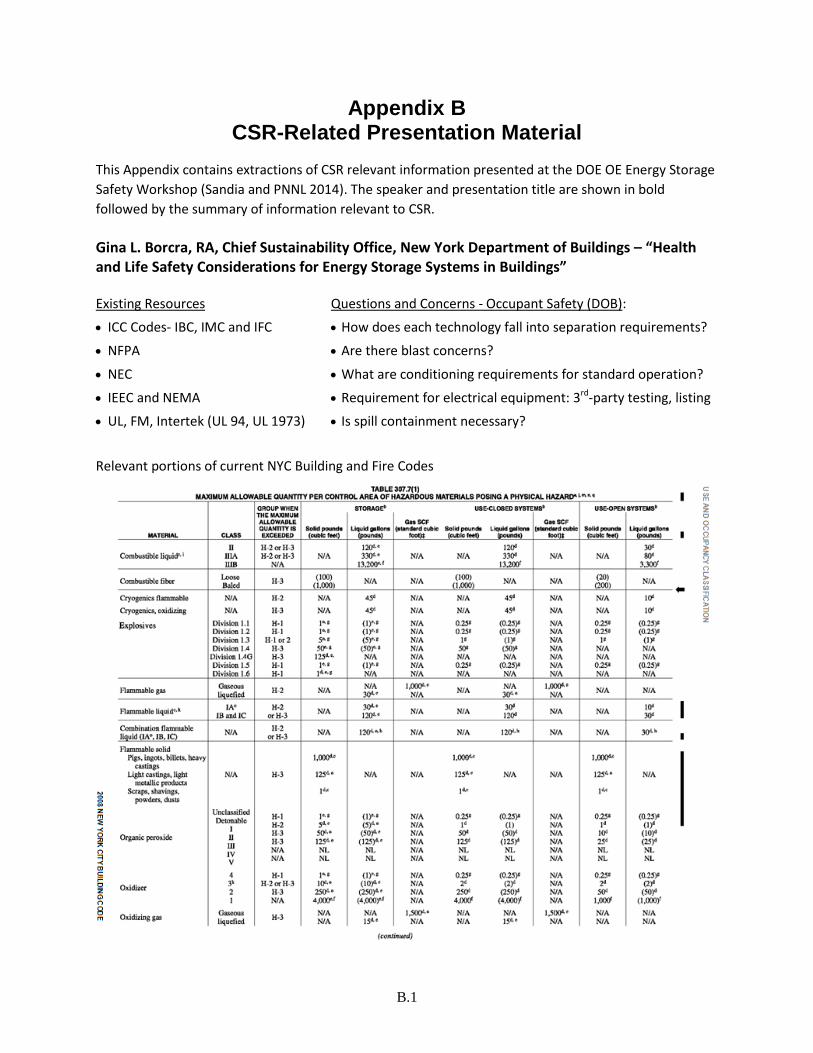
B.1
Appendix B CSR-Related Presentation Material
This Appendix contains extractions of CSR relevant information presented at the DOE OE Energy Storage
Safety Workshop (Sandia and PNNL 2014). The speaker and presentation title are shown in bold
followed by the summary of information relevant to CSR.
Gina L. Borcra, RA, Chief Sustainability Office, New York Department of Buildings – “Health and Life Safety Considerations for Energy Storage Systems in Buildings”
Existing Resources Questions and Concerns - Occupant Safety (DOB):
ICC Codes- IBC, IMC and IFC How does each technology fall into separation requirements?
NFPA Are there blast concerns?
NEC What are conditioning requirements for standard operation?
IEEC and NEMA Requirement for electrical equipment: 3rd-party testing, listing
UL, FM, Intertek (UL 94, UL 1973) Is spill containment necessary?
Relevant portions of current NYC Building and Fire Codes

B.2
Is the chemistry Corrosive, Highly toxic, or Toxic?

B.3
Questions and Concerns – Fire Safety:
What types of suppression systems are required for each battery type? Are hazardous vapors or gasses generated?
What operational changes are necessary for the FDNY depending on the chemical composition of the battery type or hazard Classifications?
Notification system requirements, internal and external to the building, alarm requirements?
Depending on the battery type, can the desired storage capacity be achieved within the existing control area requirements?
• Some recognition of stationary Battery Systems allows for their
installation in NYC • Fire Code update coming next
month

B.4
Questions and Concerns
Environmental Safety (Department of Environmental Protection)
Community Right-to-Know
What are the potential airborne or water-borne hazards?
Douglas Danley, Technical Liaison to Cooperative Research Network (CRN), Contractor at NRECA – “Energy Storage at Electric Cooperatives Overview and Safety”
•Adherence to IEE 1547, appropriate UL listings, NEC, NESC and other standards
•GIS integration – as energy storage systems become more common, it is important to know
where they are. •Documented procedures (lockouts, etc.) for
outage events
Fire Safety
•Consider whether it is better to put a large
system inside a warehouse type structure, or install as smaller, individual modules.
•Fixed Extinguishing Systems
•Are they appropriate for the planned facility?
•Easier for containerized vs. warehouse systems
•Need to address both electrical and chemical
fires
Consider what is “downwind” of the site. What would the effect of a fire with potentially noxious fumes be?
Work with the local fire authorities in advance to make sure they understand what is installed, and what plans have been developed to deal with fire emergencies.

B.5
Ryan Bowles, Corporate Environment Services, Duke Energy – “Notrees Windpower, LP and Battery Energy Storage System (BESS)”
EHS Issues/Concerns During Construction and Commissioning Each construction project will have its own unique hazards as a result of the environment, the size of
the project and/or unique work processes associated with the project. Below is a list of items we made sure that the general contractor and their sub-contractors had in place prior to work beginning. In short, a site specific construction and commissioning EHS Plan.
Company EHS Philosophy
Basic Site Safety/Training requirements
Basic Environmental requirements
Pre-Job briefing and Hazard Recognition (JHA’s)
Accountability/Discipline
Personal Protective Equipment requirements
Incident/Injury reporting and Investigation requirements
Site emergency plan and procedures
Hazard Communication/SDS/Right to Know
Blood-borne Pathogen Program
Substance Abuse Program
Equipment Safety/Operator Qualifications
Rigging and Lifting Program
Critical lift procedures/Requirements
Fall Prevention/Protection Program/Elevated Personnel Lifts
Permitting Procedures
Fire prevention/protection
Electrical Safety/Lock out/Tag out
Confined space entry
Housekeeping
Compressed gas/welding/cutting
Safety related warning signs and Barricades
Scaffold Safety/Tagging
Excavation and Trenching Safety
Arc Flash, Arc Flash Study and appropriate Arc Flash Labeling on all applicable equipment.
Stormwater Permit Coverage (if applicable), Stormwater Pollution Prevention Plan (SWP3) and BMPs
Spill Prevention, Control and Countermeasures (SPCC) Plan for Construction
Wildlife Issues – Snakes, Spiders and other Wildlife
Waste Management, Chemical Control and Inventories
Inclement Weather – Tornados, Lightning and Severe Hot or Cold Weather

B.6
Primary EHS Issues/Concerns During Operations Primary Operations and BESS EHS Issues/Concerns
High Voltage Hazards
Electrical Safety, Arc Flash and Arc Flash PPE
Lock Out/Tag Out (LOTO) Program
BESS Building Fire Suppression and Detection
Emergency Ingress and Egress
Emergency Response, Medical Emergencies and Pre-Incident Planning/Coordination with Local Emergency Responders
Personal Protective Equipment (PPE)
Ergonomics, Battery Replacement and Work From Elevated Platforms
Waste Management, Chemical Control and Inventories
Hazard Communication/SDS/Right-to-Know
Spill Prevention, Control and Countermeasures (SPCC) Plan for Operations
BESS Safety Area FE-25 Clean Agent Fire Suppression System

B.7
FE-25 Pre-Action Alarm Fike Detection System

B.8

B.9
Matt Paiss, Fire Captain, Bureau of Field Operations, San Jose Fire Department – “Safety Needs & Challenges for First Responders Or…. You want to put what where?!”
Safety Concerns Results of Concerns
1. Limited roof access 1. Vague installation guidelines
2. Confusing or non-existent labeling 2. Local Fire Marshal requirements lacking technical knowledge
3. Lack of power isolation features 3. Reduction of available roof space
4. Inadequate fault
detection/interruption 4. Inconsistent regulatory path
5. Improper grounding 5. Permit delays
6. Wire management issues 6. Increased BOS costs
Recommendations
Clear Markings
– Identification, location & disconnects
Adequate Clearances & Engineering
– Access, seismic, fire loading, and structural
Appropriate Fire Protection Systems
– Agents & application recommendations
Emergency Discharge
– Post damage response & handling
Haresh Kamath, Program Manager, Energy Storage and Distributed Generation, Electric Power Research Institute (EPRI) – “Perspectives on Needs and Challenges for Energy Storage Safety” Product Safety Best Practices
Product must demonstrably meet appropriate safety codes for the jurisdiction
–NFPA, OSHA, ANSI, IEEE, UL, and other standards bodies as appropriate –Local jurisdictions often have their own codes
Product must have an appropriate Failure Modes and Effects Analysis (FMEA)
Product must have appropriate safety mechanisms and must have a documented process for how
those mechanisms are applied
Product must have good documentation for both standard operating practice and contingency
measures

B.10
Steve Willard, P.E., PNM Resources – “Risk and Safety Issues and Solutions from Recent Storage Installations”
Michael A. Stosser, Energy Attorney, Sutherland Asbill & Brennan LLP – “What Are the Risks and What Regulations Should We Consider?” Development of Testing Standards
Most issues occur with multi-cell batteries, because of thermal instability of active materials in the
battery and interaction at high temperatures
Global independent organizations have developed testing protocols, but studies are not complete:
International Electrotechnical Commission (Safety requirements)
Underwriters Laboratories (UL) testing for batteries
Institute of Electrical and Electronic Engineers (cell batteries) Electrical Manufacturers
Association(safety standards)
Society of Automotive Engineers (electric vehicles)
United Nations (transportation of dangerous goods)
Japanese Standards Association (electric vehicles)

B.11
Battery Safety Organisation (electric vehicles and Lithium-ion)
International Electrochemical Commission (Electrical Energy Storage Systems) (TC 120 for smart
grid integration)
Common Product Safety Tests for Lithium-ion Batteries
The most commons safety tests are designed to assess specific risk from electrical, mechanical, and
environmental conditions
Electrical
o Test of current flow
o Abnormal charging test, overcharging and charging time
o Forced discharge
Mechanical
o Crush test
o Impact test
o Shock test
o Vibration test
Environmental
o Heating test
o Temperature Cycling test, testing each cell
o Low pressure altitude test
Various UL tests
Occupational Safety and Health Administration (OSHA) - Safety
Currently, OSHA captures the primary safety regulations that would relate to energy storage
installation and operation of facilities
Electricity has long been recognized as serious workplace hazard
OSHA currently has regulations that address, among others:
o Construction of electric equipment
o Eye and face protection
o Respiratory Protection
o Safety
25 states, Puerto Rico and the Virgin Islands have OSHA-approved state plans and have adopted
virtually all federal guidelines, some states have adopted different standards
Issues We Should Consider for Future Regulation – Moving Forward
Need to conduct a comprehensive review of federal, state and local regulations relating to the
construction and operation of energy storage technologies, primarily those using batteries and
electric capacitors

B.12
OSHA
National Renewable Energy Lab (NREL) Guidelines on Safety Hazards of Batteries
Construction, including applicable local building codes
Interconnection to utilities, and the North America Reliability Corporation (NERC)
Insurance
Permitting
Environmental impacts
Issues to Consider for Future Regulation
Need to develop regulations for installation of energy storage systems that address issues prior to
installation:
Compliance with UL specifications for batteries and related equipment
Fire testing
Packing, handling and transportation of batteries
Storage of batteries, especially if bulk stored in corrugated boxes
Electric Power Research Institute (EPRI)
Developing an industry forum to study safety regulations for installation of electric energy
storage systems
National Electrical Installation Standards (NEIS) and National Electrical Contractors Association
(NECA)
Developing standards for the installation of energy storage systems
Issues We Should Consider for Future Regulation
Need to develop regulations for energy storage systems after installation that include standard
operating procedures and guidelines for safety, response, containment, and aftermath
Need to focus on regulations that address prevention:
Provide specialized safety training for employees, including battery and electric capacitor fire
behavior
Create compliance programs and a culture of safety
Install pre-programmed warning signals
Provide periodic OSHA instructions on employee safety standards for storage facilities
Develop rules for containment and suppression systems for storage of batteries and related
equipment
Establish procedures for, and train, first responders to deal specifically with fire behavior of
energy storage equipment, that address battery and fire behavior

B.13
Mandate the installation of specialized fire extinguishers - both inside a storage building and in
local fire departments
Establish clear procedures for response and containment
Mandate training exercises and emergency simulations
Develop regulations for disposal, recycling, and clearing debris
Issues We Should Consider for Future Regulation
Potential Environmental Consequences
The EPA and local environmental agencies set environmental standards regarding safety for
workers and first responders after incidents – when is it safe to return or remove debris
In cases where there are no such regulations, they should be written and implemented
First responders may be subject to tort actions that result from their actions
First responders can use The Comprehensive Environmental Response, Compensation, and
Liability Act’s (CERCLA’s) Good Samaritan provision as defenses to such an action if they cause
chemicals to run off, harming the environment
These defenses must be available outside of CERCLA
Laurie Florence, Principal Engineer, UL, LLC – “Energy Storage System Safety – Standards & Certification” Overview of Current Standards
Document No. Title
ANSI UL 1973 Batteries for Use in Light Electric Rail (LER) and Stationary Applications
UL Subject 9540 Safety for Energy Storage Systems and Equipment (under development)
IEEE 3575 Guide for the Protection of Stationary Battery Systems
IEEE 1679 Recommended Practice for the Characterization and Evaluation of Emerging Energy Storage Technologies in Stationary Applications
IEC 62485-2 Safety requirements for secondary batteries and battery installations – Part 2: Stationary batteries
IEC CD 62619 Secondary cells and batteries containing alkaline or other non-acid electrolytes. - Safety requirements for secondary lithium cells and batteries, for use in industrial applications (under development)
IEC NP 62897
Stationary Energy Storage Systems with Lithium Batteries – Safety Requirements (under development)

B.14

B.15

B.16

B.17


