Inventive creation of arduino programmed gear cutting in ... · Gear cutting machines are used to...
12
© 2017 IJRTI | Volume 2, Issue 3 | ISSN: 2456-3315 IJRTI1703007 International Journal for Research Trends and Innovation (www.ijrti.org ) 30 Inventive creation of arduino programmed gear cutting in drilling machine 1 Balaji A, 2 Manoj Prabhakar, 3 Indradev 1 Assistant Professor, 2,3 UG Scholars Department of Mechatronics Engineering, Kongu Engineering College, Erode, Tamilnadu, India Abstract: This effort is an era of automation where manual effort is replaced by mechanical power in all degrees of automation. A gear is a rotating machine part having cut teeth which mesh with another toothed part to transmit torque. Gears facilitate change of speed, torque and direction of power source. Gears can be manufactured by a variety of processes including casting, machining, forging, extrusion, powder metallurgy and blanking. One of the common ways of making spur gears is by using a milling gear cutter in universal milling machine. CNC machines are also employed in large scale industries for continuous production of gears. Though, small scale industries could not afford a CNC machine for performing this single task. This paper involves the introduction of a detachable setup in an existing drilling machine for making spur gears and also the elimination of manual handling. The detachable setup consists of a special sleeve for holding the milling gear cutter and a cross slide for linear bed movement. The circular indexing table is replaced by DC Stepper Motor for step indexing of the work piece. Automation of this process of gear cutting is achieved by employing Arduino UNO. This project eliminates the need of separate machines for gear cutting and drilling operations. By using this detachable setup in drilling machine we can perform gear cutting operation in drilling machine itself. This project would find its way in small scale industries where they could not afford to buy a milling machine for performing this single task. Index Terms: Arduino UNO, gear cutting, Nema 34 DC Stepper motor, RMCS-1101 Motor Driver I. INTRODUCTION Gears are an integral part of the power transmission system as they are used for transferring toque or power from prime mover to the location where it is needed or will be used. Gear cutting machines are used to generate gears by rolling a gear blank with a rotating cutter known as hob. Milling machines are generally employed in small scale industries for performing this operation. Automation of gear cutting operation is achieved by using CNC machines but it is mostly used in large scale industries only. By considering the fact that small scale industries could not afford to buy separate machines for performing different tasks, we got motivated to minimize the capital investment of these industries by introducing a detachable setup in an existing drilling machine. II. EXISTING MACHINES Gear cutting machines are used to make chain gears, gears with straight and slanted teeth through processes such as hobbing and shaping. Gear cutting machines are used to generate gears by rolling a gear blank with a rotating cutter known as hob. A CNC gear cutting machine is shown in fig 1.1.
Transcript of Inventive creation of arduino programmed gear cutting in ... · Gear cutting machines are used to...

© 2017 IJRTI | Volume 2, Issue 3 | ISSN: 2456-3315
IJRTI1703007 International Journal for Research Trends and Innovation (www.ijrti.org) 30
Inventive creation of arduino programmed gear
cutting in drilling machine 1Balaji A,
2Manoj Prabhakar,
3Indradev
1Assistant Professor, 2,3UG Scholars
Department of Mechatronics Engineering,
Kongu Engineering College, Erode, Tamilnadu, India
Abstract: This effort is an era of automation where manual effort is replaced by mechanical power in all degrees of
automation. A gear is a rotating machine part having cut teeth which mesh with another toothed part to transmit torque.
Gears facilitate change of speed, torque and direction of power source. Gears can be manufactured by a variety of
processes including casting, machining, forging, extrusion, powder metallurgy and blanking. One of the common ways of
making spur gears is by using a milling gear cutter in universal milling machine. CNC machines are also employed in
large scale industries for continuous production of gears. Though, small scale industries could not afford a CNC machine
for performing this single task. This paper involves the introduction of a detachable setup in an existing drilling machine
for making spur gears and also the elimination of manual handling. The detachable setup consists of a special sleeve for
holding the milling gear cutter and a cross slide for linear bed movement. The circular indexing table is replaced by DC
Stepper Motor for step indexing of the work piece. Automation of this process of gear cutting is achieved by employing
Arduino UNO. This project eliminates the need of separate machines for gear cutting and drilling operations. By using
this detachable setup in drilling machine we can perform gear cutting operation in drilling machine itself. This project
would find its way in small scale industries where they could not afford to buy a milling machine for performing this
single task.
Index Terms: Arduino UNO, gear cutting, Nema 34 DC Stepper motor, RMCS-1101 Motor Driver
I. INTRODUCTION
Gears are an integral part of the power transmission system as they are used for transferring toque or power from prime mover
to the location where it is needed or will be used. Gear cutting machines are used to generate gears by rolling a gear blank with a
rotating cutter known as hob. Milling machines are generally employed in small scale industries for performing this operation.
Automation of gear cutting operation is achieved by using CNC machines but it is mostly used in large scale industries only. By
considering the fact that small scale industries could not afford to buy separate machines for performing different tasks, we got
motivated to minimize the capital investment of these industries by introducing a detachable setup in an existing drilling machine.
II. EXISTING MACHINES
Gear cutting machines are used to make chain gears, gears with straight and slanted teeth through processes such as
hobbing and shaping. Gear cutting machines are used to generate gears by rolling a gear blank with a rotating cutter known as
hob. A CNC gear cutting machine is shown in fig 1.1.

© 2017 IJRTI | Volume 2, Issue 3 | ISSN: 2456-3315
IJRTI1703007 International Journal for Research Trends and Innovation (www.ijrti.org) 31
III. DEMERITS OF EXISTING MACHINES
The above mentioned CNC machine is of high cost and the purpose of implementing this machine is only to cut gears then it might be of unwanted investment of money. However it is difficult for small scale industries to afford a huge sum of money on this
type of single machines which able to do only single operation, even though the process is completely automated.
Another major drawback in the existing system is that if to go for individual machines for individual operations the space occupied by the individual machines is comparatively high and alternatively the maintenance cost increases a lot, which cannot be
afforded by small scale industries.
IV. COMPONENTS USED AND ITS WORKING
ELECTRIC MOTOR
There are two electric motors in this proposed model, a DC motor for driving the cross slide through a belt drive and a DC
stepper motor for rotating the work piece to the preferred step angle for required number of teeth.
IV.1 DC MOTOR
The DC motor shown in the fig 2.1 is used to drive the cross slide to provide linear movement. This motor can deliver high
output torque as it consists of worm & worm wheel arrangement fitted into its shaft and is housed perfectly. Rotation is possible in
both clockwise and also in counterclockwise directions.
Specifications
The electric power supply necessary to run the DC motor is obtained from a step-down transformer and a bridge rectifier.
Voltage and Power 12 V DC, 50 Watts
Load Current 10 A
No Load Current 2 / 2.5 A
Speed 60 RPM
Torque 5 N-m
Table 2.1 Technical specifications of DC Motor
Calculations
The speed of the DC motor is reduced for slow movement of the cross slide. This is achieved by coupling the rotor of the
DC motor to a pulley by a belt drive. So, this will reduce the rotating speed while increasing the torque.
Motor pulley diameter = 0.04 m
Driven pulley diameter = 0.12 m
Therefore, Reduction Ratio = 3 : 1
Speed of the motor (Driving) = 60 RPM
Driven speed (Driven) = 20 RPM
Driving Torque = 5 N-m
Driven Torque = 15 N-m
IV.2 NEMA 34 DC STEPPER MOTOR
The circular indexing of the work piece is made through DC stepper motor shown in the fig 2.2. The stepper motor is
used to rotate the work piece to the required step angle and hold at the step angle thus providing lock mechanism for the work piece
during cutting operation.

© 2017 IJRTI | Volume 2, Issue 3 | ISSN: 2456-3315
IJRTI1703007 International Journal for Research Trends and Innovation (www.ijrti.org) 32
Specifications
The electric power supply necessary to run the DC stepper motor is obtained from a step-down transformer and a bridge rectifier.
Rated Voltage 2.8 V
Rated Current 1.68 A
Phase Current 4.2 A
Number of Phase 2
Step angle 1.8 degree
Holding Torque 45 Kg-cm / 4.41 N-m
Resistance per phase 0.87 ohm
Inductance per phase 7.3 mH
Rotor Inertia 1400 g-cm2
Configuration 4 wire bipolar motor
Table 2.2 Technical specifications of NEMA 34 DC Stepper Motor
Calculations
The torque of the DC stepper motor is increased to withstand the cutting force generated during the cutting operation. This is
achieved by coupling the rotor of the DC stepper motor to a pulley by a belt drive. So, this will increase the torque.
Motor pulley diameter = 0.04 m
Driven pulley diameter = 0.12 m
Therefore, Reduction Ratio = 3 : 1
Driving Torque = 4.41 N-m
Driven Torque = 13.24 N-m
IV.3 MICRO-STEPPING MOTOR DRIVER (RMCS-1101) The motor drivers are used for quiet and smooth operation of the motor. The RMCS-1101 motor driver shown in fig 2.3
achieves micro-stepping using a synchronous PWM output drive and high precision current feedback and this is absolutely silent
when the motor is stopped or turning slowly. It virtually eliminates stopped-motor heating regardless of power supply voltage.
The RMCS-1101’s closed-loop control gains are calibrated on start-up based on motor characteristics and also adjusted
dynamically while the motor is in motion. This control algorithm makes it capable of achieving better torque at higher speeds in
comparison to comparable drives in its range.

© 2017 IJRTI | Volume 2, Issue 3 | ISSN: 2456-3315
IJRTI1703007 International Journal for Research Trends and Innovation (www.ijrti.org) 33
Technical Specifications
Supply Voltage 18 – 80 Volts DC
Phase Current 1 – 7 Amps
Power Dissipation 0 – 7 Watts
Short-Circuit Current 7 – 10 Amps
PUL and DIR
Voltage
2.5 – 7 Volts DC
Step Frequency 200 kHz
Direction setup time 500 ns
Table 2.3 Technical specifications of RMCS-1101 Motor Drive
Power and Motor Terminal Assignments
The table 2.4 and 2.5 shows the terminal and input assignments for the stepper motor respectively with the motor driver
and supply voltage terminals for the motor.
Terminal
No.
Termina
l Name
Description
Terminal 1 B- Motor Coil
Phase B-
Terminal 2 B+ Motor Coil
Phase B+
Terminal 3 A- Motor Coil
Phase A-
Terminal 4 A+ Motor Coil
Phase A+
Terminal 5 +V
Power
+Ve (18 V – 80
V DC)
Terminal 6 GND Power -Ve
Table 2.4 Terminal Assignments of RMCS-1101 Motor Driver
Pulse and Direction Input Assignments
Terminal
No.
Termina
l Name
Description
Terminal 1 ENA- Enable (Motor
Free) -Ve optically isolated
input
Terminal 2 ENA+ Enable (Motor
Free) +Ve optically isolated
input
Terminal 3 DIR- Direction -Ve
optically isolated
input
Terminal 4 DIR+ Direction +Ve
optically isolated
input
Terminal 5 PUL- Pulse -Ve
optically isolated
input
Terminal 6 PUL+ Pulse +Ve
optically isolated
input
Table 2.5 Input Assignments of RMCS-1101 Motor Driver
Switch Selection for Motor Coil Current Setting
Based on the current rating of the motor, the driver has to be set for quiet and smooth operation of the motor. The table 2.6
shows the various switch selections for the motor coil current rating. The switches should be kept on while operating the motor to
provide correct current rating and to prevent motor from overloading.
© 2017 IJRTI | Volume 2, Issue 3 | ISSN: 2456-3315
IJRTI1703007 International Journal for Research Trends and Innovation (www.ijrti.org) 34
Peak
Current
SW 6 SW 7 SW 8
1.00A OFF OFF OFF
2.00A OFF OFF ON
2.80A OFF ON OFF
3.30A OFF ON ON
4.20A ON OFF OFF
5.00A ON OFF ON
6.00A ON ON OFF
7.00A ON ON ON
Table 2.6 Switch Selection for Motor Coil Current Setting
Switch Selection for Step Resolution Setting
Steps/Re
v SW 1 SW 2 SW 3 SW 4
200 ON ON ON ON
400 OFF ON ON ON
800 ON OFF ON ON
1000 OFF OFF ON ON
2000 ON ON OFF ON
3200 OFF ON OFF ON
4000 ON OFF OFF ON
8000 OFF OFF OFF ON
1600 ON ON ON OFF
6400 OFF ON ON OFF
10000 ON OFF ON OFF
12000 OFF OFF ON OFF
12500 ON ON OFF OFF
12800 OFF ON OFF OFF
16000 ON OFF OFF OFF
20000 OFF OFF OFF OFF
Table 2.7 Switch Selection for Step Resolution Setting The table 2.7 shows the various switch selection for the step resolution setting for the stepper motor to drive according to the
required step angle. For various steps per revolution the switches of the motor driver is to be kept ON/OFF.
Calculations The number of pulse to the stepper motor is decided on the number of teeth to be cut and the pulley ratio. By calculating the
resolution we can find the required pulse for the operation.
Assuming the number of teeth to cut is 25. Based on this the resolution and pulse are calculated.
Angle to be tilted for each tooth = 3600 / 24 = 150
Steps per revolution = 12000
Required Resolution = 3600 / Steps per revolution = 3600 / 12000 = 0.030
Number of Operating Pulses = Angle to be tilted / Required Resolution = 150 / 0.030 = 500 Pulses
Motor pulley diameter = 0.04 m
Driven pulley diameter = 0.12 m
Therefore, Reduction Ratio = 3 : 1
Therefore, the actual number of operating pulses to be loaded by considering the pulley ratio is,
Number of Operating Pulses = 3 x 500 = 1500 Pulses
IV.4 INDUCTION MOTOR
An induction or asynchronous motor is an AC electric motor in which the electric current in the rotor needed to produce torque
is obtained by electromagnetic induction from the magnetic field of the stator winding. An induction motor therefore does not require mechanical commutation, separate-excitation or self-excitation for all or part of the energy transferred from stator to rotor,
as in universal, DC and large synchronous motors. An induction motor's rotor can be either wound type or squirrelcage type.
Three-phase squirrel-cage induction motors are widely used in industrial drives because they are rugged, reliable and economical. Single-phase induction motors are used extensively for smaller loads, such as household appliances like fans.
Although traditionally used in fixed-speed service, induction motors are increasingly being used with variable-frequency drives
(VFDs) in variable-speed service. VFDs offer especially important energy savings opportunities for existing and prospective
induction motors in variable-torque centrifugal fan, pump and compressor load applications. Squirrel cage induction motors are
© 2017 IJRTI | Volume 2, Issue 3 | ISSN: 2456-3315
IJRTI1703007 International Journal for Research Trends and Innovation (www.ijrti.org) 35
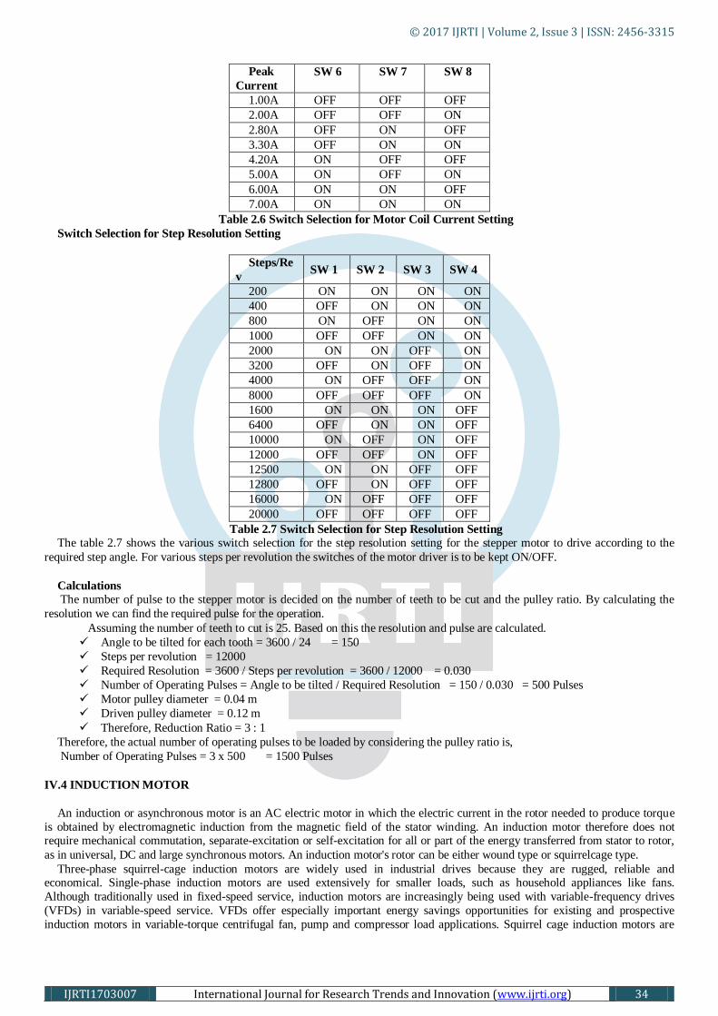
very widely used in both fixed-speed and variable-frequency drive (VFD) applications. Variable voltage and variable frequency
drives are also used in variable-speed service. A three phase induction motor is shown in fig 2.4.
Specifications
The table 2.8 shows the technical specifications of the three phase induction motor.
Voltage 440 V
Current 3 A
Speed 2800 RPM
Connection Delta
Horse Power 1 HP
Table 2.8 Technical specifications of 3 phase Induction Motor
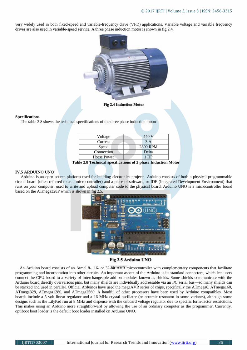
IV.5 ARDUINO UNO
Arduino is an open-source platform used for building electronics projects. Arduino consists of both a physical programmable
circuit board (often referred to as a microcontroller) and a piece of software, or IDE (Integrated Development Environment) that
runs on your computer, used to write and upload computer code to the physical board. Arduino UNO is a microcontroller board
based on the ATmega328P which is shown in fig 2.5.
An Arduino board consists of an Atmel 8-, 16- or 32-bit AVR microcontroller with complementary components that facilitate
programming and incorporation into other circuits. An important aspect of the Arduino is its standard connectors, which lets users
connect the CPU board to a variety of interchangeable add-on modules known as shields. Some shields communicate with the
Arduino board directly overvarious pins, but many shields are individually addressable via an I²C serial bus—so many shields can
be stacked and used in parallel. Official Arduinos have used the megaAVR series of chips, specifically the ATmega8, ATmega168,
ATmega328, ATmega1280, and ATmega2560. A handful of other processors have been used by Arduino compatibles. Most
boards include a 5 volt linear regulator and a 16 MHz crystal oscillator (or ceramic resonator in some variants), although some designs such as the LilyPad run at 8 MHz and dispense with the onboard voltage regulator due to specific form-factor restrictions.
This makes using an Arduino more straightforward by allowing the use of an ordinary computer as the programmer. Currently,
optiboot boot loader is the default boot loader installed on Arduino UNO.

© 2017 IJRTI | Volume 2, Issue 3 | ISSN: 2456-3315
IJRTI1703007 International Journal for Research Trends and Innovation (www.ijrti.org) 36
Specifications
The technical specifications of the Arduino UNO and other related specifications are described on the table 2.9.
Microcontroller ATmega328
Operating Voltage 5 V
Input Voltage
(recommended)
7 – 12 V
Input Voltage (limits) 6 – 20 V
Digital I/O Pins 14 (of which 6
provide PWM output)
Analog Input Pins 6
DC Current per I/O
Pin
40 mA
DC Current for 3.3 V
Pin
50mA
DC Current for 3.3 V
Pin
X 32 KB
(ATmega328) of which
0.5 KB used by boot
loader
SRAM 2 KB (ATmega328)
EEPROM 1 KB (ATmega328)
Clock Speed 16 MHz
Length 68.6 mm
Width 53.4 mm
Weight 25
Table 2.9 Technical specifications of Arduino UNO
IV.6 RELAY
A relay is an electrically operated switch. Many relays use an electromagnet to mechanically operate a switch, but other
operating principles are also used, such as solid-state relays. Relays are used where it is necessary to control a circuit by a low-
power signal (with complete electrical isolation between control and controlled circuits), or where several circuits must be
controlled by one signal. The first relays were used in long distance telegraph circuits as amplifiers: they repeated the signal coming
in from one circuit and re-transmitted it on another circuit. Relays were used extensively in telephone exchanges and early
computers to perform logical operations.
A type of relay that can handle the high power required to directly control an electric motor or other loads is called a contactor.
Solid-state relays control power circuits with no moving parts, instead using a semiconductor device to perform switching. Relays
with calibrated operating characteristics and sometimes multiple operating coils are used to protect electrical circuits from overload
or faults; in modern electric power systems these functions are performed by digital instruments still called "protective relays".
When an electric current is passed through the coil it generates a magnetic field that activates the armature and the consequent movement of the movable contact either makes or breaks (depending upon construction) a connection with a fixed contact. If the
set of contacts was closed when the relay was de-energized, then the movement opens the contacts and breaks the connection, and
vice versa if the contacts were open. When the current to the coil is switched off, the armature is returned by a force, approximately
half as strong as the magnetic force, to its relaxed position. Usually this force is provided by a spring, but gravity is also used
commonly in industrial motor starters. Most relays are manufactured to operate quickly. In a low-voltage application this reduces
noise; in a high voltage or current application it reduces arcing.
IV.7 TRANSFORMER
The transformer is a static electrical device that transfers energy by inductive coupling between its winding circuits. A varying
current in the primary winding creates a varying magnetic flux in the transformer's core and thus a varying magnetic flux through

© 2017 IJRTI | Volume 2, Issue 3 | ISSN: 2456-3315
IJRTI1703007 International Journal for Research Trends and Innovation (www.ijrti.org) 37
the secondary winding. This varying magnetic flux induces a varying electromotive force (E.M.F) or voltage in the secondary
winding. The transformer has cores made of high permeability silicon steel. The steel has a permeability many times that of free
space and the core thus serves to greatly reduce the magnetizing current and confine the flux to a path which closely couples the
windings. A 12-0-12 step down transformer is shown in fig 2.7.
A varying current in the transformer's primary winding creates a varying magnetic flux in the core and a varying magnetic field
impinging on the secondary winding. This varying magnetic field at the secondary induces a varying electromotive force (EMF) or
voltage in the secondary winding. The primary and secondary windings are wrapped around a core of infinitely high magnetic
permeability so that all of the magnetic flux passes through both the primary and secondary windings. With a voltage source
connected to the primary winding and load impedance connected to the secondary winding, the transformer currents flow in the
indicated directions. According to Faraday's law of induction, since the same magnetic flux passes through both the primary and
secondary windings in an ideal transformer, a voltage is induced in each winding in the secondary winding case, according to the primary winding case. The primary EMF is sometimes termed counter EMF. This is in accordance with Lenz's law, which states
that induction of EMF always opposes development of any such change in magnetic field. The transformer winding voltage ratio is
thus shown to be directly proportional to the winding turns ratio. According to the law of Conservation of Energy, any load
impedance connected to the ideal transformer's secondary winding results in conservation of apparent, real and reactive power.
Instrument transformer, with polarity dot and X1 marking on LV side terminal. The ideal transformer is a reasonable approximation
for the typical commercial transformer, with voltage ratio and winding turns ratio both being inversely proportional to the
corresponding current ratio.
IV.8 MILLING GEAR CUTTER
The milling gear cutter is a cutting tool used to cut the teeth into the work piece. Based on the module various types of gear tooth
profile can be made. A milling gear cutter is shown in fig 2.8. The cutter is generally made of high speed steel (HSS), carbide,
cobalt, etc.
Specification
The technical specifications of the milling gear cutter are shown in the table 2.10.
Material High Speed Steel
Module 2.25 mm
Pitch Circle Diameter 55 mm
Addendum Circle
Diameter
63 mm
Bore Diameter 30 mm
Table 2.10 Technical Specifications of Milling Gear Cutter
© 2017 IJRTI | Volume 2, Issue 3 | ISSN: 2456-3315
IJRTI1703007 International Journal for Research Trends and Innovation (www.ijrti.org) 38
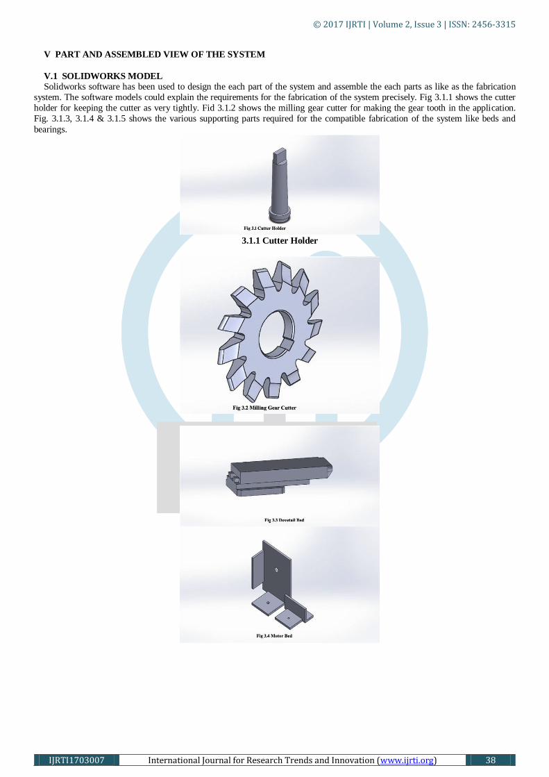
V PART AND ASSEMBLED VIEW OF THE SYSTEM
V.1 SOLIDWORKS MODEL
Solidworks software has been used to design the each part of the system and assemble the each parts as like as the fabrication
system. The software models could explain the requirements for the fabrication of the system precisely. Fig 3.1.1 shows the cutter
holder for keeping the cutter as very tightly. Fid 3.1.2 shows the milling gear cutter for making the gear tooth in the application.
Fig. 3.1.3, 3.1.4 & 3.1.5 shows the various supporting parts required for the compatible fabrication of the system like beds and
bearings.
3.1.1 Cutter Holder

© 2017 IJRTI | Volume 2, Issue 3 | ISSN: 2456-3315
IJRTI1703007 International Journal for Research Trends and Innovation (www.ijrti.org) 39
ASSEMBLED VIEW
The whole assembled setup which will be fitted in the drilling machine is shown in the figure 3.1.6.
VI WORKING OF THE MACHINE BLOCK DIAGRAM
V. 1 Methodology
VI.2 WORKING PRINCIPLE
The program from Arduino IDE software is fed into the Arduino UNO through USB cable. Transformer powers the stepper
motor and wiper motor through relay and motor driver. The stepper holds the work piece without free rotation with its holding
torque till the pulse is given. Initially the drilling machine is powered with a three phase supply thereby rotating the spindle
containing the gear cutter. The wiper motor moves the cross slide forward initially. During its forward move, a tooth profile is cut.
The wiper motor continues to rotate in clockwise direction till the cross slide touches the limit switch LS1. Then the wiper motor
© 2017 IJRTI | Volume 2, Issue 3 | ISSN: 2456-3315
IJRTI1703007 International Journal for Research Trends and Innovation (www.ijrti.org) 40
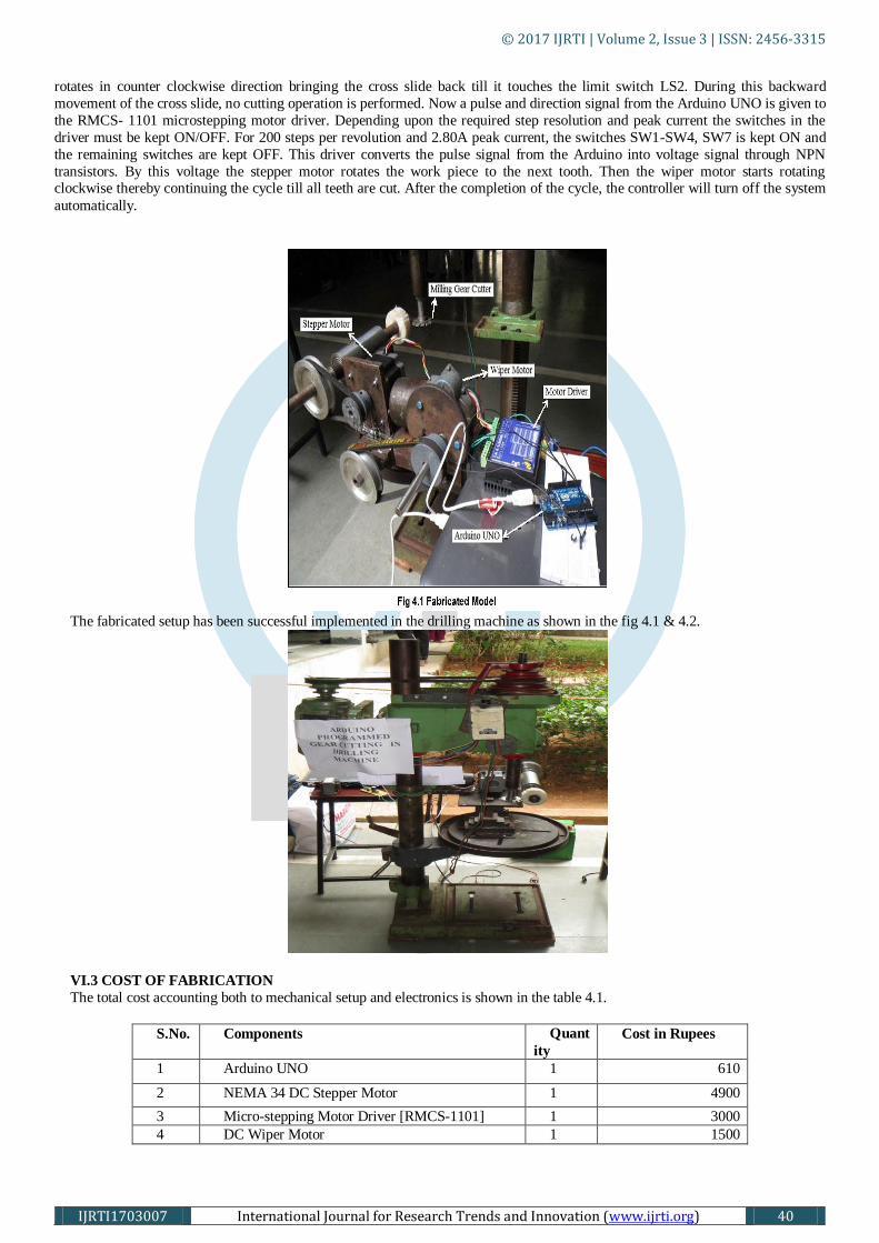
rotates in counter clockwise direction bringing the cross slide back till it touches the limit switch LS2. During this backward
movement of the cross slide, no cutting operation is performed. Now a pulse and direction signal from the Arduino UNO is given to
the RMCS- 1101 microstepping motor driver. Depending upon the required step resolution and peak current the switches in the
driver must be kept ON/OFF. For 200 steps per revolution and 2.80A peak current, the switches SW1-SW4, SW7 is kept ON and
the remaining switches are kept OFF. This driver converts the pulse signal from the Arduino into voltage signal through NPN
transistors. By this voltage the stepper motor rotates the work piece to the next tooth. Then the wiper motor starts rotating clockwise thereby continuing the cycle till all teeth are cut. After the completion of the cycle, the controller will turn off the system
automatically.
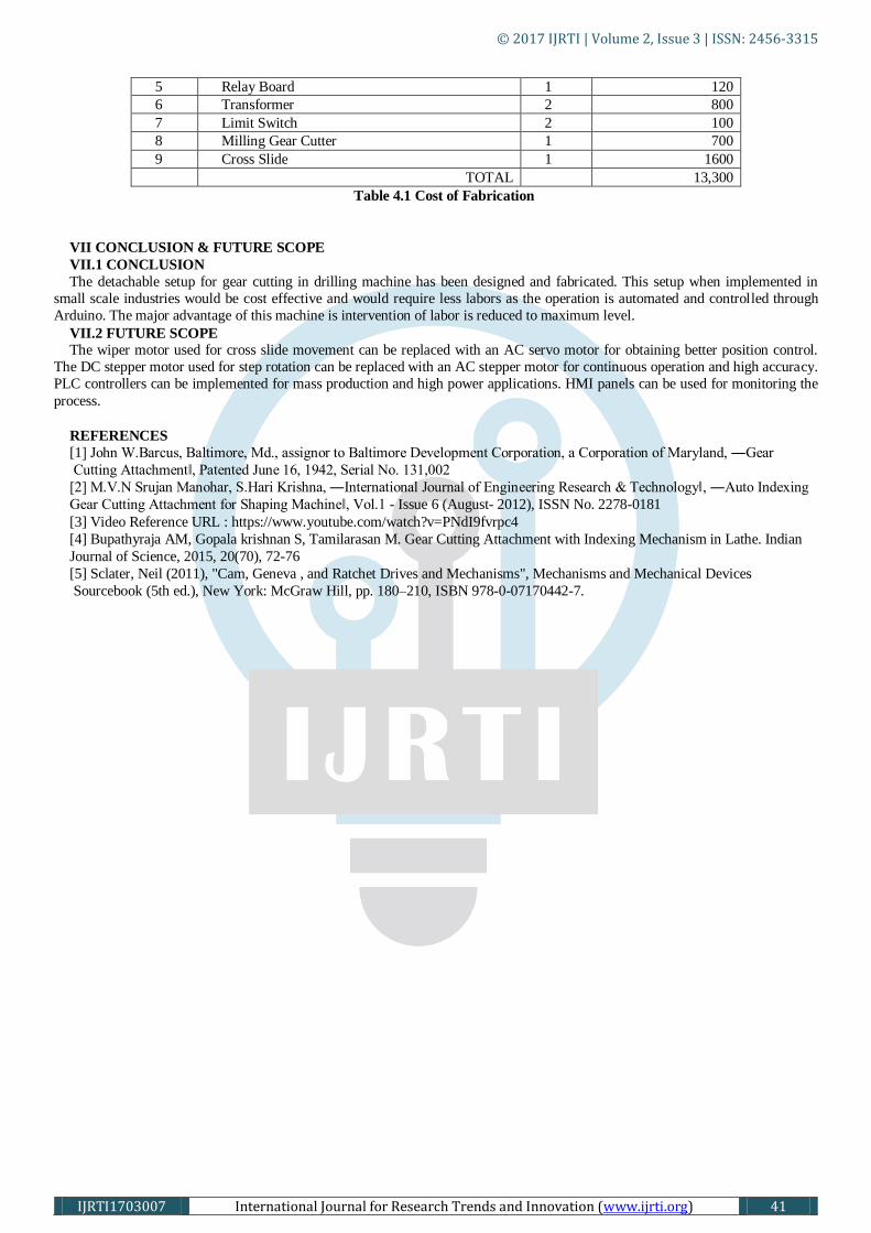
The fabricated setup has been successful implemented in the drilling machine as shown in the fig 4.1 & 4.2.
VI.3 COST OF FABRICATION
The total cost accounting both to mechanical setup and electronics is shown in the table 4.1.
S.No. Components Quant
ity
Cost in Rupees
1 Arduino UNO 1 610
2 NEMA 34 DC Stepper Motor 1 4900
3 Micro-stepping Motor Driver [RMCS-1101] 1 3000
4 DC Wiper Motor 1 1500
© 2017 IJRTI | Volume 2, Issue 3 | ISSN: 2456-3315
IJRTI1703007 International Journal for Research Trends and Innovation (www.ijrti.org) 41
5 Relay Board 1 120
6 Transformer 2 800
7 Limit Switch 2 100
8 Milling Gear Cutter 1 700
9 Cross Slide 1 1600
TOTAL 13,300
Table 4.1 Cost of Fabrication
VII CONCLUSION & FUTURE SCOPE
VII.1 CONCLUSION
The detachable setup for gear cutting in drilling machine has been designed and fabricated. This setup when implemented in
small scale industries would be cost effective and would require less labors as the operation is automated and controlled through
Arduino. The major advantage of this machine is intervention of labor is reduced to maximum level.
VII.2 FUTURE SCOPE
The wiper motor used for cross slide movement can be replaced with an AC servo motor for obtaining better position control.
The DC stepper motor used for step rotation can be replaced with an AC stepper motor for continuous operation and high accuracy.
PLC controllers can be implemented for mass production and high power applications. HMI panels can be used for monitoring the
process.
REFERENCES
[1] John W.Barcus, Baltimore, Md., assignor to Baltimore Development Corporation, a Corporation of Maryland, ―Gear
Cutting Attachment‖, Patented June 16, 1942, Serial No. 131,002
[2] M.V.N Srujan Manohar, S.Hari Krishna, ―International Journal of Engineering Research & Technology‖, ―Auto Indexing
Gear Cutting Attachment for Shaping Machine‖, Vol.1 - Issue 6 (August- 2012), ISSN No. 2278-0181
[3] Video Reference URL : https://www.youtube.com/watch?v=PNdI9fvrpc4
[4] Bupathyraja AM, Gopala krishnan S, Tamilarasan M. Gear Cutting Attachment with Indexing Mechanism in Lathe. Indian
Journal of Science, 2015, 20(70), 72-76
[5] Sclater, Neil (2011), "Cam, Geneva , and Ratchet Drives and Mechanisms", Mechanisms and Mechanical Devices
Sourcebook (5th ed.), New York: McGraw Hill, pp. 180–210, ISBN 978-0-07170442-7.