Introduction to Wireless MIMO – Theory and Applications · PDF fileIntroduction to...
63
CEWIT - Center of Excellence in Wireless and Information Technology Introduction to Wireless MIMO – Theory and Applications Dr. Jacob Sharony Director, Network Technologies Division Center of Excellence in Wireless & IT Stony Brook University www.ece.sunysb.edu/~jsharony IEEE LI, November 15, 2006 Multipath is not enemy but al l y
Transcript of Introduction to Wireless MIMO – Theory and Applications · PDF fileIntroduction to...

CEWIT - Center of Excellence in Wireless and Information Technology
Introduction to Wireless MIMO –Theory and Applications
Dr. Jacob SharonyDirector, Network Technologies Division
Center of Excellence in Wireless & ITStony Brook University
www.ece.sunysb.edu/~jsharony
IEEE LI, November 15, 2006
Multipath is not enemy but ally

CEWIT - Center of Excellence in Wireless and Information Technology
Why MIMO
• Motivation: current wireless systems– Capacity constrained networks– Issues related to quality and coverage
• MIMO exploits the space dimension to improve wireless systems capacity, range and reliability
• MIMO-OFDM – the corner stone of future broadband wireless access– WiFi – 802.11n– WiMAX – 802.16e (a.k.a 802.16-2005)– 3G / 4G

CEWIT - Center of Excellence in Wireless and Information Technology
Transmission on a multipath channel
• Time variations: Fading => SNR variations• Time spread => frequency selectivity
In wireless communication the propagation channel is characterized bymultipath propagation due to scattering on different obstacles
CEWIT - Center of Excellence in Wireless and Information Technology
Transmission on a multipath channel
• The received level variations result in SNR variations• The received level is sensitive to the transmitter and receiver locations
Fading:

CEWIT - Center of Excellence in Wireless and Information Technology
MIMO Defined
• MIMO is an acronym that stands for Multiple Input Multiple Output.
• It is an antenna technology that is used both in transmission and receiver equipment for wireless radio communication.
• There can be various MIMO configurations. For example, a 2x2 MIMO configuration is 2 antennas to transmit signals (from base station) and 2 antennas to receive signals (mobile terminal).
Transmitter Receiver

CEWIT - Center of Excellence in Wireless and Information Technology
No. of AntennaElements
Channel Capacity
logarithmic
linearMIMO
C = log2 (1+SNR)
C = log2 (det[I+SNR/M H
SIMO/MISO
HT])
MIMO vs. SIMO/MISO(Linear vs. Logarithmic Improvement)

CEWIT - Center of Excellence in Wireless and Information Technology
How MIMO Works
• MIMO takes advantage of multi-path.
• MIMO uses multiple antennas to send multiple parallel signals (from transmitter).
• In an urban environment, these signals will bounce off trees, buildings, etc. and continue on their way to their destination (the receiver) but in different directions.
• “Multi-path” occurs when the different signals arrive at the receiver at various times.
• With MIMO, the receiving end uses an algorithm or special signalprocessing to sort out the multiple signals to produce one signal that has the originally transmitted data.

CEWIT - Center of Excellence in Wireless and Information Technology
How MIMO Works (cont.)
Multiple data streams transmitted in a single channel at the same time
Multiple radios collect multipath signals
Delivers simultaneous speed, coverage, and reliability improvements

CEWIT - Center of Excellence in Wireless and Information Technology
Types of MIMO
• MIMO involves Space Time Transmit Diversity (STTD), Spatial Multiplexing (SM) and Uplink Collaborative MIMO.
• Space Time Transmit Diversity (STTD) - The same data is coded and transmitted through different antennas, which effectively doubles the power in the channel. This improves Signal Noise Ratio (SNR) for cell edge performance.
• Spatial Multiplexing (SM) - the “Secret Sauce” of MIMO. SM delivers parallel streams of data to CPE by exploiting multi-path. It can double (2x2 MIMO) or quadruple (4x4) capacity and throughput. SM gives higher capacity when RF conditions are favorable and users are closer to the BTS.
• Uplink Collaborative MIMO Link - Leverages conventional single Power Amplifier (PA) at device. Two devices can collaboratively transmit on the same sub-channel which can also double uplink capacity.

CEWIT - Center of Excellence in Wireless and Information Technology
Space-Time Transmit DiversityAlamouti Code
time
space
CEWIT - Center of Excellence in Wireless and Information Technology
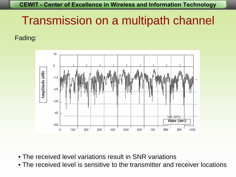
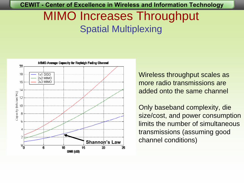
MIMO Increases ThroughputSpatial Multiplexing
Wireless throughput scales as more radio transmissions are added onto the same channel
Only baseband complexity, die size/cost, and power consumption limits the number of simultaneous transmissions (assuming good channel conditions)Shannon’s Law

CEWIT - Center of Excellence in Wireless and Information Technology
MIMO Channel Capacity

CEWIT - Center of Excellence in Wireless and Information Technology
MIMO Increases Range
Each multipath route is treated as a separate channel, creating many “virtual wires” over which to transmit signals
Traditional radios are confused by this multipath, while MIMO takes advantage of these “echoes” to increase range and throughput

CEWIT - Center of Excellence in Wireless and Information Technology
Single Radio Performance (Office)

CEWIT - Center of Excellence in Wireless and Information Technology
MIMO Performance (Office)

CEWIT - Center of Excellence in Wireless and Information Technology
Single Radio vs. MIMO Performance
SDTV HDTV 30 Mbps ADSL
HDTV + SDTV + Gaming + Music + Internet + Voice
CEWIT - Center of Excellence in Wireless and Information Technology
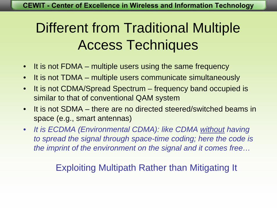
Different from Traditional MultipleAccess Techniques
• It is not FDMA – multiple users using the same frequency• It is not TDMA – multiple users communicate simultaneously• It is not CDMA/Spread Spectrum – frequency band occupied is
similar to that of conventional QAM system• It is not SDMA – there are no directed steered/switched beams in
space (e.g., smart antennas)• It is ECDMA (Environmental CDMA): like CDMA without having
to spread the signal through space-time coding; here the code is the imprint of the environment on the signal and it comes free…
Exploiting Multipath Rather than Mitigating It
CEWIT - Center of Excellence in Wireless and Information Technology
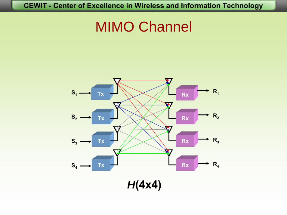
MIMO Channel
S1 Tx Rx R1
S2
S3
S4
Tx
Tx
Tx Rx
Rx
Rx R2
R3
R4
H(4x4)

CEWIT - Center of Excellence in Wireless and Information Technology
using laser diodes using radio frequency
The “Magic”:Separating the self-coded signals
CEWIT - Center of Excellence in Wireless and Information Technology
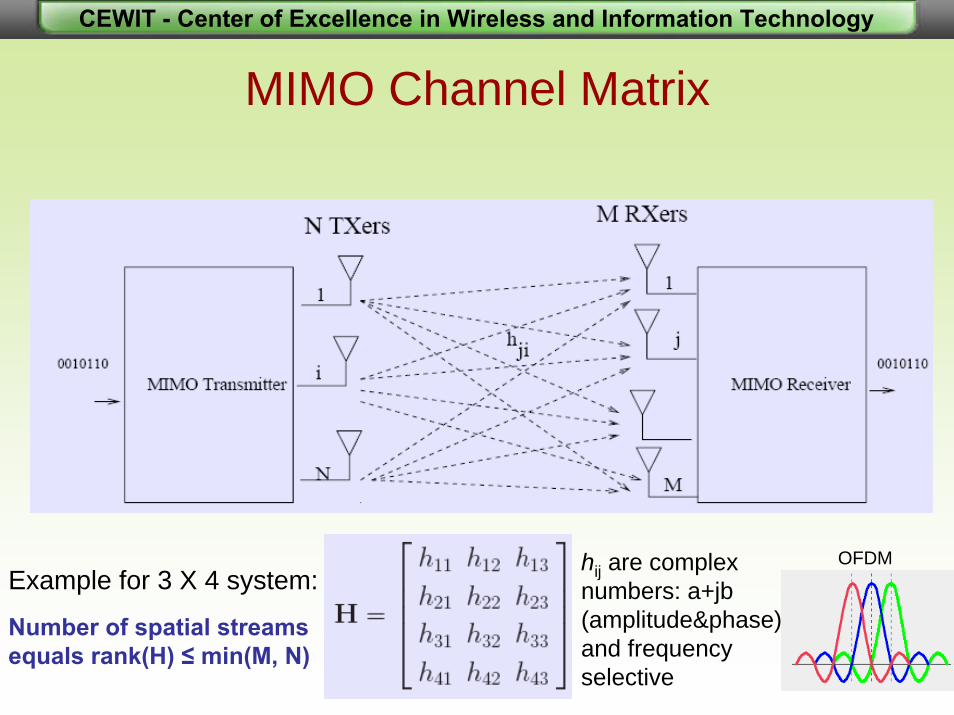
MIMO Channel Matrix
Example for 3 X 4 system:hij are complex numbers: a+jb(amplitude&phase)and frequency selective
Number of spatial streamsequals rank(H) ≤ min(M, N)
OFDM

CEWIT - Center of Excellence in Wireless and Information Technology
How It Works
Example for 3 X 3 system:

CEWIT - Center of Excellence in Wireless and Information Technology
Impact of Channel Model
MIMO performance is very sensitive to channel matrix invertibility
The following degrades the conditioning of the channel matrix:• Antenna correlation caused by: - small antenna spacing, or- small angle spread
Line of sight component compared with multipath fading component:- multipath fading component, close to i.i.d. random, is wellconditioned- Line of sight component is very poorly conditioned.

CEWIT - Center of Excellence in Wireless and Information Technology
MIMO-SM in Line-of-Site
The system is near rank one (non invertible)!
Spatial multiplexing requires multipath to work!!!

CEWIT - Center of Excellence in Wireless and Information Technology
Zero-Forcing Receiver
Zero Forcing implements matrix (pseudo)-inverse (ignores noiseenhancement problems):
Where,

CEWIT - Center of Excellence in Wireless and Information Technology
ExampleSimultaneous Transmission of 3 Different Bit-Streams
001011 0, 2, 3 1, -1, -i
Data Bit/symbolMapping QPSK
Q
I
RayleighFading
AGWN-i
1-1
Channel
R1R2R3
S1 S2 S3
‘0’‘1’
‘2’‘3’

CEWIT - Center of Excellence in Wireless and Information Technology
Downstream Signalsall signals sent at same frequency and same time
APS1
S2
S3S4
S1S2S3S4 S1S2S3S4
MU

CEWIT - Center of Excellence in Wireless and Information Technology
e.g., R1= h11S1 + h12S2 + h13S3 + h14S4 + n1
Mixed SignalsDownstream
R=H · S + n
channel mixing matrix
noise
S1
S2
S3
S4
R1
R2
R3
R4
h11
h12
h44
h41
h21
MUAP

CEWIT - Center of Excellence in Wireless and Information Technology
The Received Signals
R1 = h11S1 + h12S2 + h13S3 + h14S4 + nR2 = h21S1 + h22S2 + h23S3 + h24S4 + nR3 = h31S1 + h32S2 + h33S3 + h34S4 + nR4 = h41S1 + h42S2 + h43S3 + h44S4 + n
nSHR +⋅=
SHHRHS ⋅⋅≈⋅⇐ −− 11ˆ
⎟⎟⎟⎟⎟
⎠
⎞
⎜⎜⎜⎜⎜
⎝
⎛
=
44434241
34333231
24232221
14131211
hhhhhhhhhhhhhhhh
H
YIf H is ill-conditioned (close to singular)Y will be far from the identity matrix Resulting in co-channel interference

CEWIT - Center of Excellence in Wireless and Information Technology
Spatial Correlation or how well the matrix H is conditioned

CEWIT - Center of Excellence in Wireless and Information Technology
Spatial Correlation (cont.)

CEWIT - Center of Excellence in Wireless and Information Technology
Spatial Correlation (cont.)Correlation Drops Significantly for D>λ When Angle
Spread >65°

CEWIT - Center of Excellence in Wireless and Information Technology
Co-Channel Interference
IHHY trueest ≠⋅= −1
⎟⎟⎟⎟⎟
⎠
⎞
⎜⎜⎜⎜⎜
⎝
⎛
=
44434241
34333231
24232221
14131211
yyyyyyyyyyyyyyyy
Y
SYS ⋅⇐ˆ
∑≠
=
kjkj
kkS
y
ySINR
klog20

CEWIT - Center of Excellence in Wireless and Information Technology
Cf = log2 (det[I+SNR/M H HT]) / log2 (1+hhTSNR)
SNR=30 dB
SNR=10 dB
SNR→∞
SNR=20 dB
Graceful Capacity Degradation in Partially Correlated Channels
Multi-pathcomponentsdo not needto be fullyindependent

CEWIT - Center of Excellence in Wireless and Information Technology
Random Capacity in MIMO ChannelsCorrelation Effect

CEWIT - Center of Excellence in Wireless and Information Technology
s11 s12 s13…s21 s22 s23…s31 s32 s33…s41 s42 s43… S4
S3
S2
S1
s11 s12 s13…
s21 s22 s23…
s31 s32 s33…
s41 s42 s43…
Collaborative MIMODownstream
AP
MU
R4R3R2R1 S1
S2
S3
S4
S1
S2
S3S4
Four 4x4 mixing matrices, one for each MU
CEWIT - Center of Excellence in Wireless and Information Technology
s11 s12 s13…s21 s22 s23…s31 s32 s33…s41 s42 s43… R4
R3
R2
R1
s11 s12 s13…
s21 s22 s23…
s31 s32 s33…
s41 s42 s43…
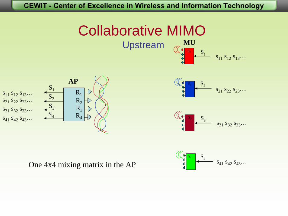
Collaborative MIMOUpstream MU
S1 S1
APS1
S2
S3S4
S2
S3
S4
S2
S3
S4
One 4x4 mixing matrix in the AP

CEWIT - Center of Excellence in Wireless and Information Technology
e.g., R1= h11S1 + h12S2 + h13S3 + h14S4 + n1
Mixed ChannelsUpstream
R=H · S + n
channel mixing matrix
noise
S1
S2
S3
S4
R1
R2
R3
R4
h11
h12
h44
h41
h21
Four different MU’s
Single AP
MU1
MU2
MU3
MU4

CEWIT - Center of Excellence in Wireless and Information Technology
MIMO Pre-Processing at the TransmitterA single antenna at the mobile
• AP pre-processes the signals based on channel knowledge (CSI Tx)
• No MIMO processing in the mobile• AP sends linear combination of all signals from each
antenna such that when they all arrive at the mobile all undesired signals cancel out
• Effectively AP solves the equation to each mobile• Benefits:
– Mobile: lower cost, power and size– Scalability: more MIMO channels possible resulting in higher
aggregate capacity– Strong physical-layer security, hard to break

CEWIT - Center of Excellence in Wireless and Information Technology
s11 s12 s13…s21 s22 s23…s31 s32 s33…s41 s42 s43… S’4
S’3
S’2
S’1
AP
S2
S3S4
MIMO Pre-Processing at the TransmitterA single antenna at the mobile
S1
All undesired signals cancel out at the mobile
s11 s12 s13…
s21 s22 s23…
s31 s32 s33…
s41 s42 s43…
MUS1
S2
S3
S4

CEWIT - Center of Excellence in Wireless and Information Technology
e.g., R1= h11S’1 + h12S’2 + h13S’3 + h14S’4 + n1
Mixed ChannelsDownstream
R=H · S’ + n
channel mixing matrix
noise
S’1
S’2
S’3
S’4
R1h11
h31
h41
h21
Single MUSingle antenna
Single AP

CEWIT - Center of Excellence in Wireless and Information Technology
MIMO Pre-Processing at the Transmitter Downlink
IHHY esttrue ≠⋅= −1
SYS ⋅⇐ˆ
nSHR +⋅=
SWS ⋅=′
nSWHnSHR +⋅⋅=+′⋅=′
Y1−= HW

CEWIT - Center of Excellence in Wireless and Information Technology
End-to-End Reciprocity
Tx Rx
TxRx
AP MU
T_ap
R_ap T_mu
R_mu
H_D
H_U
• Practically, downstream and upstream channel matrices are not reciprocal• AP Tx/Rx chain mismatch could result in significant performance degradation

CEWIT - Center of Excellence in Wireless and Information Technology
H’_D=R_mu H_D T_AP end-to-end downstream H’_U=R_AP H_U T_mu end-to-end upstream, estimated using training sequence
Note that R_mu, T_mu, R_AP and T_AP are diagonal matrices H_D and H_U are the channel matrices (antenna-to-antenna) for downstream andupstream, respectively
H_D= R-1_mu H’_D T-1_AP antenna-to-antenna downstream H_U= R-1_AP H’_U T-1_mu antenna-to-antenna upstream
H_D= H T_U reciprocity from EM theoryR-1_mu H’_D T-1_AP = (R-1_AP H’_U T-1_mu) TR-1_mu H’_D T-1_AP = T-1_mu H’ T_U R-1_AP
H’_D= R_mu T-1_mu H’ T_U R-1_APT_AP
Note that R_mu and T_mu are unknownH’_U, T_AP and R_AP are known
End-to-End Reciprocity (cont.)

CEWIT - Center of Excellence in Wireless and Information Technology
P’_D=H’ T_U R-1_AP T_AP matrix used for pre-processing
Y=R_mu H_D T_AP P’-1_D = R_mu H_D T_AP (H’ T_U R-1_AP T_AP) –1
Y= R_mu H_D T_AP((R_AP H_U T_mu) T R-1_AP T_AP) –1
Y= R_mu H_D T_AP(T_mu H T_U R_AP R-1_AP T_AP ) –1
Y= R_mu H_D T_AP(T_mu H_D R_AP R-1_APT_AP ) –1
Y= R_mu H_D T_AP(T_mu H_DT_AP ) –1
Y= R_mu H_D T_AP T-1_AP H-1_D T-1_mu
Y= R_mu H_D H-1_D T-1_mu highly diagonal (low interference)
Calibration at the AP

CEWIT - Center of Excellence in Wireless and Information Technology
P’_D=H’ T_U matrix used for pre-processing
Y=R_mu H_D T_AP P’ -1_D = R_mu H_D T_AP (H’ T_U ) –1
Y= R_mu H_D T_AP((R_AP H_U T_mu) T ) –1
Y= R_mu H_D T_AP(T_mu H T_U R_AP ) –1
Y= R_mu H_D T_AP(T_mu H_D R_AP ) –1
Y= R_mu H_D T_AP R -1_AP H -1_D T -1_mu
diagonality could be spoiled resultingin interference
No Calibration at the AP

CEWIT - Center of Excellence in Wireless and Information Technology
End-to-End ReciprocityConclusions
• AP Tx/Rx mismatch could result in significant performance degradation
• MU Tx/Rx mismatch has relatively small effect on performance • Calibration in the AP is necessary and sufficient

CEWIT - Center of Excellence in Wireless and Information Technology
Mobility Effects
• Motions of mobiles change the channel matrix• Since the packet length is very short, the change of channel matrix
is supposed to be negligible. Estimation of channel matrix usingheader (preamble) only is considered as the channel responses for decoding the entire packet.
• The SINR results are much worse than what were expected originally. The reason is: when the condition number of H is very high, H-1 is very sensitive to small changes of H.
• SINR for some multiplexing channels may be less than 10dB even when the displacement of a Tx or Rx is less than 2% of the wavelength
• Better estimation of channel matrix is required.

CEWIT - Center of Excellence in Wireless and Information Technology
Effect of MobiltyStatistical Model
)cos)/2((~ pp xj
ppik eah ϕλπθ Δ+−∑=pj
ppik eah θ−∑=
Δx
][0,2uniformly iid πθ p
i
k
p
][0,2uniformly iid , πϕθ pp

CEWIT - Center of Excellence in Wireless and Information Technology
9 Mobiles; None MoveInput SNR=20dB
SINR’s constants and finite (imperfect channel estimation due to noise)
0 5 10 15 200
5
10configuration
0 5 10 15100
102
104
condition number of H
0 5 1020
30
40
50downlink
0 5 100
20
40
60uplink
Hea
der o
nly
displacement (0.25% wavelength)

CEWIT - Center of Excellence in Wireless and Information Technology
9 Mobiles; 1 MovesInput SNR=20dB
-Uplink: ALL SINR’s are deteriorating as the displacement increases except that for the moving mobile
-Downlink: ALL SINR’sremain unchanged except that for the moving mobile
0 5 10 15 200
5
10configuration
0 5 10 15101
102
condition number of H
0 5 1020
30
40
500 5 10
10
20
30
40uplink
displacement (0.25% wavelength)
downlink

CEWIT - Center of Excellence in Wireless and Information Technology
Applications
• WLAN – WiFi 802.11n• Mesh Networks (e.g., MuniWireless)• WMAN – WiMAX 802.16e• 4G• RFID• Digital Home

CEWIT - Center of Excellence in Wireless and Information Technology
High Throughput WiFi - 802.11nGeneral
• Using the space dimension (MIMO) to boost data rates up to 600 Mbps through multiple antennas and signal processing
• Target applications include: large files backup, HD streams, online interactive gaming, home entertainment, etc.
• Backwards compatible with 802.11a/b/g

CEWIT - Center of Excellence in Wireless and Information Technology
High Throughput WiFi - 802.11nTechnology Overview
• 2.4 GHz and 5.8 GHz unlicensed bands• Channel bandwidth of 20 MHz and 40 MHz• Up to 4 spatial streams (e.g., 4x4)• Current product offerings (pre-N) use only 2 spatial
streams with 3Tx / 3Rx in the AP and 2Tx / 3Rx in the mobile supporting up to 300 Mbps
• Spatial diversity, spatial multiplexing, beamforming• Enhancements in both PHY and MAC (e.g., frame
aggregation, block-ACK, space-time coding, power save, green field mode, etc.)

CEWIT - Center of Excellence in Wireless and Information Technology
• High capacity (MIMO) cross-links• WiFi access
MIMO in MuniWireless

CEWIT - Center of Excellence in Wireless and Information Technology
• A collection of wireless mobile nodes that self-configure to form a network (data rate + range)
• No fixed infrastructure is required• Any two nodes can communicate with each other• High capacity link are useful for scalability and multimedia services
MIMO in Ad-Hoc Network
single-hop comm.multi-hop comm.

CEWIT - Center of Excellence in Wireless and Information Technology
Mobile-WiMAX 802.16eTechnology Overview
• Non line of site, up to 4-6 mbps per user for a few km
• 2.5 GHz (US) and 3.5 GHz licensed bands
• Channel bandwidth from 1.25 to 20 MHz
• QPSK, 16 QAM and 64 QAM modulation
• OFDMA access (orthogonal uplink)
• TDD for asymmetric traffic and flexible BW allocation
• Advanced Antenna Systems (AAS): Beamforming, spatial diversity, spatial multiplexing using MIMO (2x2)
CEWIT - Center of Excellence in Wireless and Information Technology
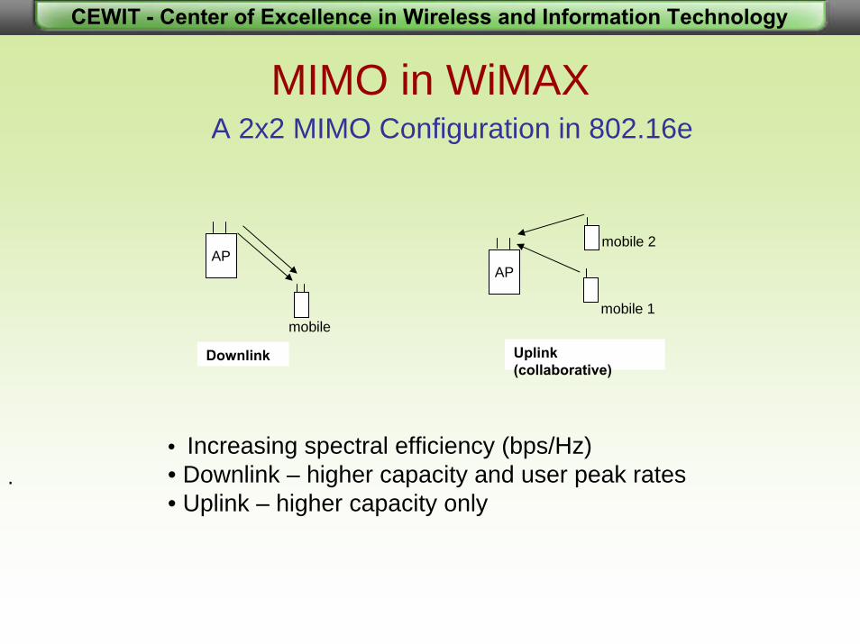
MIMO in WiMAX
.
A 2x2 MIMO Configuration in 802.16e
mobile
APAP
mobile 2
Downlink
mobile 1
Uplink (collaborative)
• Increasing spectral efficiency (bps/Hz)• Downlink – higher capacity and user peak rates• Uplink – higher capacity only

CEWIT - Center of Excellence in Wireless and Information Technology
MIMO in WiMAX (cont.)
OFDMA TDD Frame Structure
Time/Frequency Multi-User Diversity

CEWIT - Center of Excellence in Wireless and Information Technology
MIMO in WiMAX (cont.)Layer 3 Throughput Comparison

CEWIT - Center of Excellence in Wireless and Information Technology
MIMO in RFID
. • Increasing read reliability using space diversity• Increasing read range and read throughput• Full channel information at the reader comes for free (tag backscatter)

CEWIT - Center of Excellence in Wireless and Information Technology
MIMO Enables the Digital Home
MIMO delivers whole home coverage with the speed and reliability to stream multimedia applications
MIMO can reliably connect cabled video devices, computer networking devices, broadband connections, phone lines, music, storage devices, etc.
MIMO is interoperable and can leverage the installed based of 802.11 wireless that is already deployed: computers, PDAs, handheld gaming devices, cameras, VoIP Phones, etc.

CEWIT - Center of Excellence in Wireless and Information Technology
Kitchen
Bedroom
Living Room –TV Displays and Gaming
Home Service Gateway
Home Theater and Set Top Box
Home Office
Children’s Room
The Ultimate Digital HomeWiFi 802.11n

CEWIT - Center of Excellence in Wireless and Information Technology
Questions ?
Contact Information:[email protected]
Thank You!