Introduction to Thermoelectric Materials and...
21
Space probe to the Jupiter From JPL, NASA Radioisotope Thermoelectric Generator (PbTe) Introduction to Thermoelectric Materials and Devices 7th Semester of 2012 2012.05.10, Thursday Department of Energy Science Sungkyunkwan University
Transcript of Introduction to Thermoelectric Materials and...
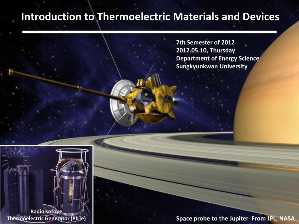
Space probe to the Jupiter From JPL, NASA Radioisotope
Thermoelectric Generator (PbTe)
Introduction to Thermoelectric Materials and Devices
7th Semester of 2012 2012.05.10, Thursday Department of Energy Science Sungkyunkwan University
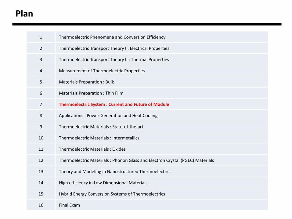
1 Thermoelectric Phenomena and Conversion Efficiency
2 Thermoelectric Transport Theory I : Electrical Properties
3 Thermoelectric Transport Theory II : Thermal Properties
4 Measurement of Thermoelectric Properties
5 Materials Preparation : Bulk
6 Materials Preparation : Thin Film
7 Thermoelectric System : Current and Future of Module
8 Applications : Power Generation and Heat Cooling
9 Thermoelectric Materials : State-of-the-art
10 Thermoelectric Materials : Intermetallics
11 Thermoelectric Materials : Oxides
12 Thermoelectric Materials : Phonon Glass and Electron Crystal (PGEC) Materials
13 Theory and Modeling in Nanostructured Thermoelectrics
14 High efficiency in Low Dimensional Materials
15 Hybrid Energy Conversion Systems of Thermoelectrics
16 Final Exam
Plan
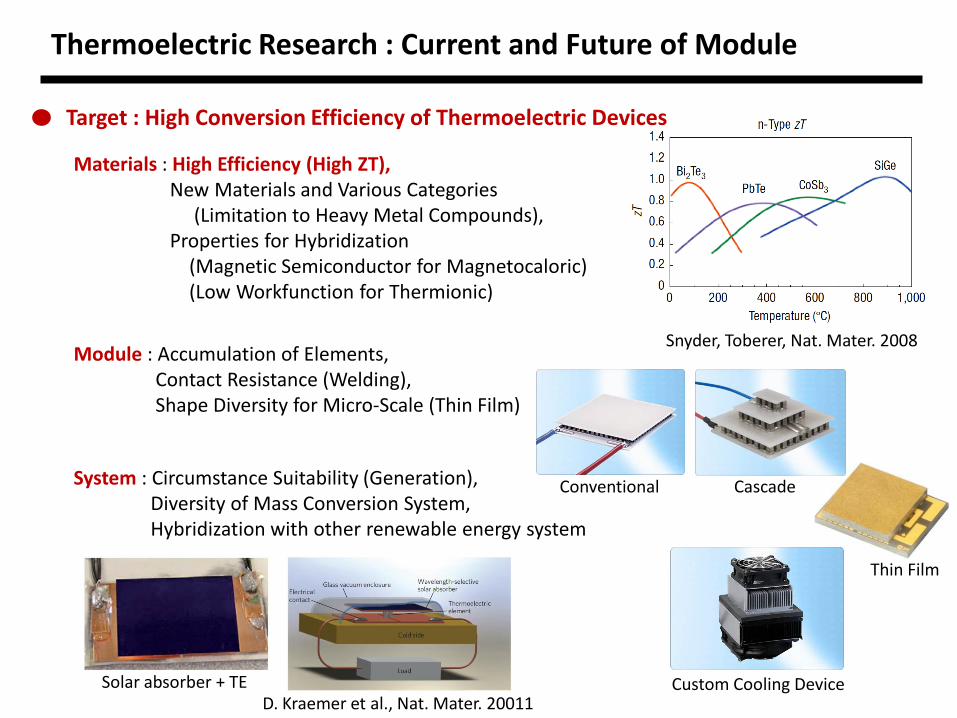
Snyder, Toberer, Nat. Mater. 2008
Thermoelectric Research : Current and Future of Module
Target : High Conversion Efficiency of Thermoelectric Devices
Module : Accumulation of Elements, Contact Resistance (Welding), Shape Diversity for Micro-Scale (Thin Film)
System : Circumstance Suitability (Generation), Diversity of Mass Conversion System, Hybridization with other renewable energy system
Materials : High Efficiency (High ZT), New Materials and Various Categories (Limitation to Heavy Metal Compounds), Properties for Hybridization (Magnetic Semiconductor for Magnetocaloric) (Low Workfunction for Thermionic)
Thin Film
Cascade Conventional
Solar absorber + TE Custom Cooling Device D. Kraemer et al., Nat. Mater. 20011
Thermoelectric module design
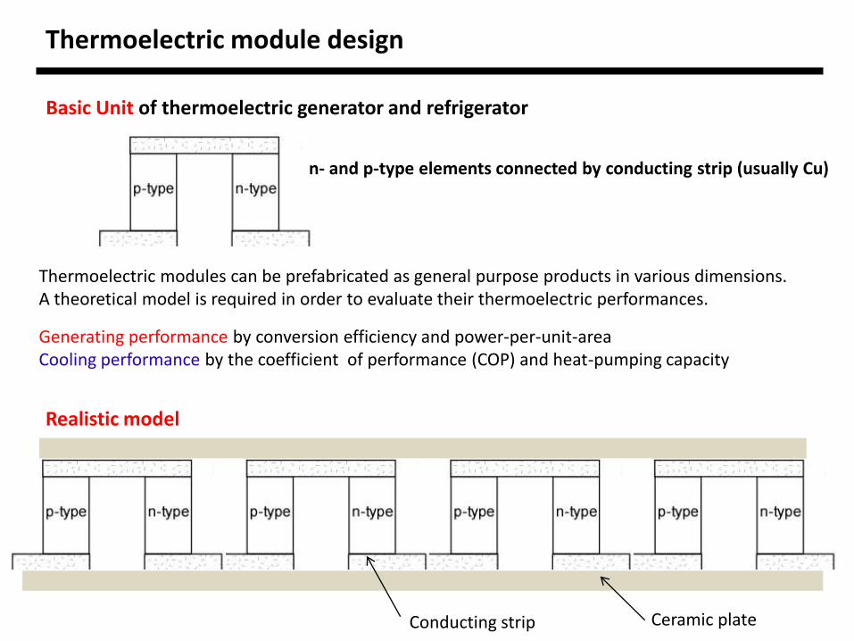
Basic Unit of thermoelectric generator and refrigerator
n- and p-type elements connected by conducting strip (usually Cu)
Thermoelectric modules can be prefabricated as general purpose products in various dimensions. A theoretical model is required in order to evaluate their thermoelectric performances.
Generating performance by conversion efficiency and power-per-unit-area Cooling performance by the coefficient of performance (COP) and heat-pumping capacity
Conducting strip Ceramic plate
Realistic model
Thermoelectric module design
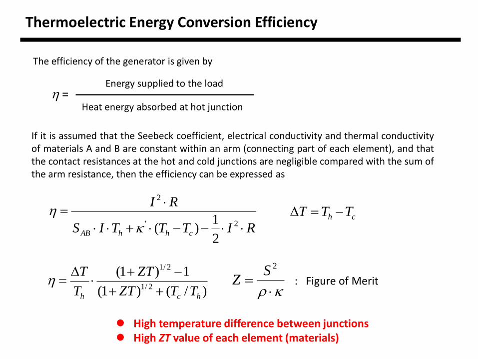
Thermoelectric Energy Conversion Efficiency
The efficiency of the generator is given by
= Heat energy absorbed at hot junction
Energy supplied to the load
If it is assumed that the Seebeck coefficient, electrical conductivity and thermal conductivity of materials A and B are constant within an arm (connecting part of each element), and that the contact resistances at the hot and cold junctions are negligible compared with the sum of the arm resistance, then the efficiency can be expressed as
RITTTIS
RI
chhAB
2'
2
2
1)(
)/()1(
1)1(2/1
2/1
hch TTZT
ZT
T
T
ch TTT
2SZ : Figure of Merit
High temperature difference between junctions High ZT value of each element (materials)
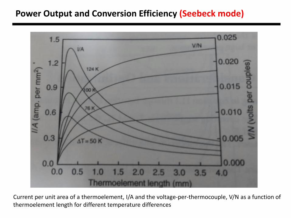
Power Output and Conversion Efficiency (Seebeck mode)
Current per unit area of a thermoelement, I/A and the voltage-per-thermocouple, V/N as a function of thermoelement length for different temperature differences
Power Output and Conversion Efficiency
2
22
)/21)((
)(
2 lrlln
TTANP
c
ch
)]2
)(4
()(5.02[)/21(
)(
2
chh
chc
h
ch
rll
nl
ZTT
TTlrl
T
TT
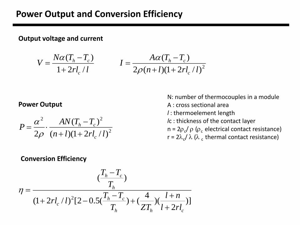
Power Output
Conversion Efficiency
Output voltage and current
lrl
TTNV
c
ch
/21
)(
2)/21)((2
)(
lrlln
TTAI
c
ch
N: number of thermocouples in a module A : cross sectional area l : thermoelement length lc : thickness of the contact layer n = 2c/ (c electrical contact resistance) r = 2c/ ( c thermal contact resistance)
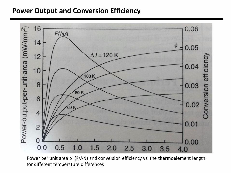
Power per unit area p=(P/AN) and conversion efficiency vs. the thermoelement length for different temperature differences
Power Output and Conversion Efficiency

Design consideration and optimization
1. Specifications : The operating temperature Tc and Th, the required output voltage V, current, I and power output, P. 2. Material parameters : Thermoelectric properties (3 parameters), and the module contact properties n and r. 3. Design parameters : Thermoelement length l, the cross-sectional area A, and the number of the thermocouples, N.
fmc
tp
cc
c: cost-per-kilowatt-hour cm : fabrication cost of a thermoelectric module cf : input thermal energy cost per kilowatt hour t : operating period

Coefficient of performance, heat pumping capacity (Peltier mode)
]/
]1)1(
)1(
)[/21(2/1
2/1
lrl
ln
ZTl
T
T
ln
ZTl
TT
Tlrl c
c
h
ch
cc
Coefficient of performance (COP)
Heat pumping capacity per unit area, q
/2
)( max
cc rlrll
TTq
2/2
max cZTT , maximum temperature difference when the load at the cold-side is zero
Coefficient of performance, heat pumping capacity (Peltier mode)
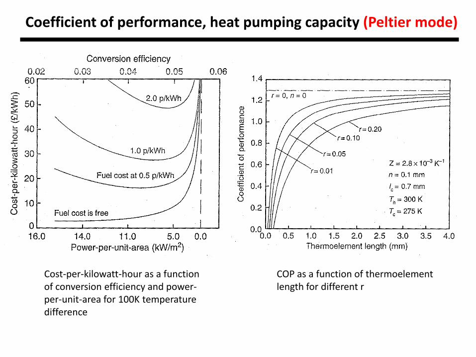
Cost-per-kilowatt-hour as a function of conversion efficiency and power-per-unit-area for 100K temperature difference
COP as a function of thermoelement length for different r

Coefficient of performance, heat pumping capacity (Peltier mode)
COP as a function of temperature difference across the module for different contact parameter
Heat pumping capacity as a function of thermoelement length for different contact parameter
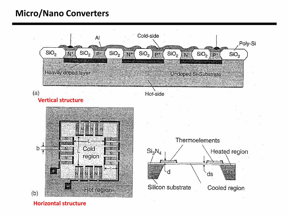
Micro/Nano Converters
Vertical structure
Horizontal structure
Micro/Nano Converters
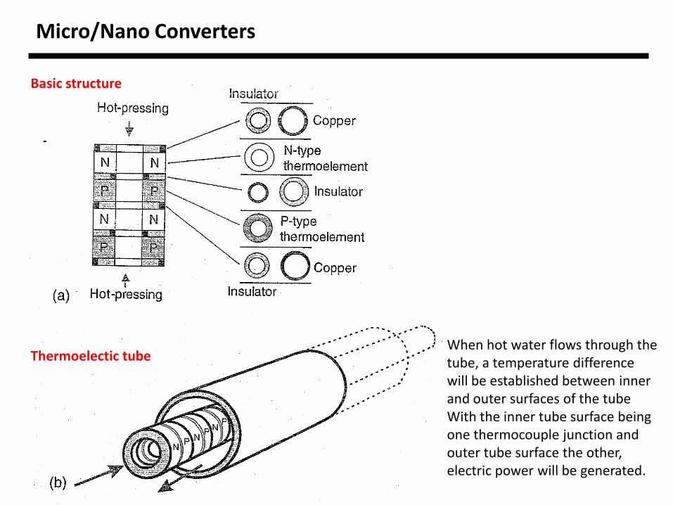
Basic structure
Thermoelectic tube When hot water flows through the tube, a temperature difference will be established between inner and outer surfaces of the tube With the inner tube surface being one thermocouple junction and outer tube surface the other, electric power will be generated.
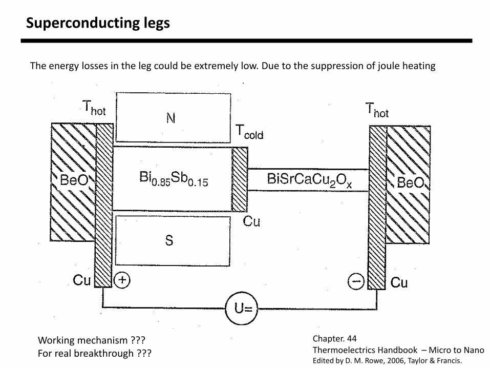
Superconducting legs
The energy losses in the leg could be extremely low. Due to the suppression of joule heating
Working mechanism ??? For real breakthrough ???
Chapter. 44 Thermoelectrics Handbook – Micro to Nano Edited by D. M. Rowe, 2006, Taylor & Francis.
Special Guest
Dr. Kyu-Hyoung Lee SAIT, Samsung Electronics. Co. Ltd. Studied since 2005
Title : Nanostructuring of conventional thermoelectric materials
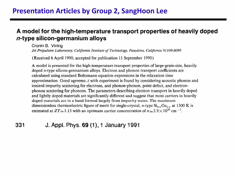
Presentation Articles by Group 2, SangHoon Lee
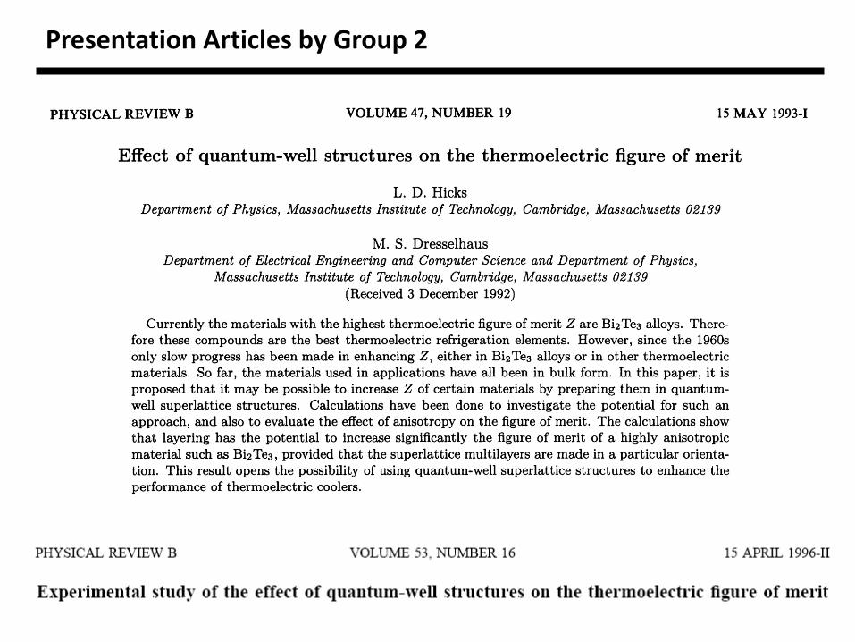
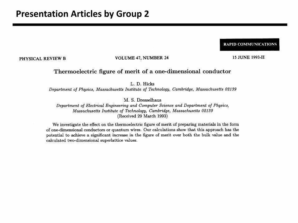
Presentation Articles by Group 2
Presentation Articles by Group 2
Presentation Articles by Group 2