Introduction to SolidWorks 2009 - DCGsccs-dcg.weebly.com/uploads/1/3/9/5/13957485/lego_block.pdf ·...
22
Introduction to SolidWorks 2009 Part Modelling – Lego Block Design & Communication Graphics 1 Introduction to SolidWorks 2009
Transcript of Introduction to SolidWorks 2009 - DCGsccs-dcg.weebly.com/uploads/1/3/9/5/13957485/lego_block.pdf ·...
Introduction to SolidWorks 2009 Part Modelling – Lego Block
Design & Communication Graphics 1
Introduction to SolidWorks 2009

Introduction to SolidWorks 2009 Part Modelling – Lego Block
Design & Communication Graphics 2
Getting started
The first part that you will build is a Lego Brick. To begin building the part, you
need to open a new SolidWorks part document. The new part document will be
created based on a template. A template forms the foundation of a new
document. The template can include user-defined parameters, annotations,
or geometry. Templates allow you to define your only specific parameters, and
then open new documents with those customised settings already set.
In this way, you define parameters only once and the new documents are created
with the customised settings. This saves a lot of repetitive work each time you
use SolidWorks
Note: The Sensors (only available in SW’s 2009) tool located in the FeatureManager
monitors selected properties in a part or assembly and alerts you when they deviate
from a pre-specified limit. There are four sensor types: Mass properties, Measurement,
Interference Detection and Simulation data.
Starting SolidWorks and Opening a New Part
Start the SolidWorks application.
Click the Start menu from the Windows interface.
Click All Programs, SolidWorks 2008, SolidWorks 2008.
Tip: You can quickly start a SolidWorks session by double-clicking the left mouse button
on the desktop shortcut, if there is a shortcut icon on the system desktop.
Open a new part.
Click New from the Menu Bar toolbar. The New
SolidWorks Document dialog box is displayed.
Note: When SolidWorks 2008/09 is installed it
automatically references the templates from 2006.
Click the Part template
Click OK from the New SolidWorks Document
dialog box. A new Part document window is
displayed.

Introduction to SolidWorks 2009 Part Modelling – Lego Block
Design & Communication Graphics 3
Set System units.
Click Options , Document Properties tab
from the Menu Bar toolbar. The Document
Properties - Drafting Standard dialog box is
displayed.
ANSI is the default Overall drafting standard.
Click Units. Select MMGS, (millimeter, gram, second).
Click inside the Length Decimals box. Select .12
decimal places from the dropdown menu for Basic unit
length. Accept the default settings.
Click OK from the Document Properties - Units dialog box. Return to the SolidWorks Graphics area.
Begin Sketching
Solid models are built from features. Initially, features are based on 2D sketches. The sketch is the basis for a
3D model. Create a 2D sketch that you will later make into a 3D solid.
Sketches are flat or planar. In the same way as we need a sheet of paper on which to sketch you need to choose
a plane on which to sketch in SolidWorks. A SolidWorks part contains three default sketch planes. They
represent the Front, Top, and Right planes.
Left click on the Top plane and choose Sketch
Choose S on the keyboard. A context sensitive toolbar appears with a variety of sketch tools.
Note: The toolbar appears where the cursor
was last clicked.
Similar commands are grouped into consolidated flyout buttons on the toolbar.
These buttons appear with an arrow next to them eg. Rectangle.

Introduction to SolidWorks 2009 Part Modelling – Lego Block
Design & Communication Graphics 4
Click the Centre Rectangle tool from the shortcut toolbar. The Rectangle
PropertyManager is displayed. The Centre Rectangle tool is displayed on the mouse icon.
Place the centre of the rectangle on the origin
and drag the rectangle as shown.
Left click in the graphics area to position the
rectangle.
Press Esc on the keyboard to exit the command
Zoom to fit.
Press the f key on the keyboard to return to the full Graphics area.
Note: The horizontal and coincident geometrical relations are
automatically added.
Smart Dimension
Choose S to activate the shortcut toolbar and choose Smart Dimension .
Add the dimensions shown across.
The sketch turns black and is fully defined
Exiting the sketch.
Three options exist to exit the sketch. As in SolidWorks 2006 you may exit the sketch by choosing
Exit Sketch from the confirmation corner or choose Exit Sketch from the CommandManager
The third option, new to SW 2008, is to double left click on a blank space in the graphics area
Introduction to SolidWorks 2009 Part Modelling – Lego Block
Design & Communication Graphics 5
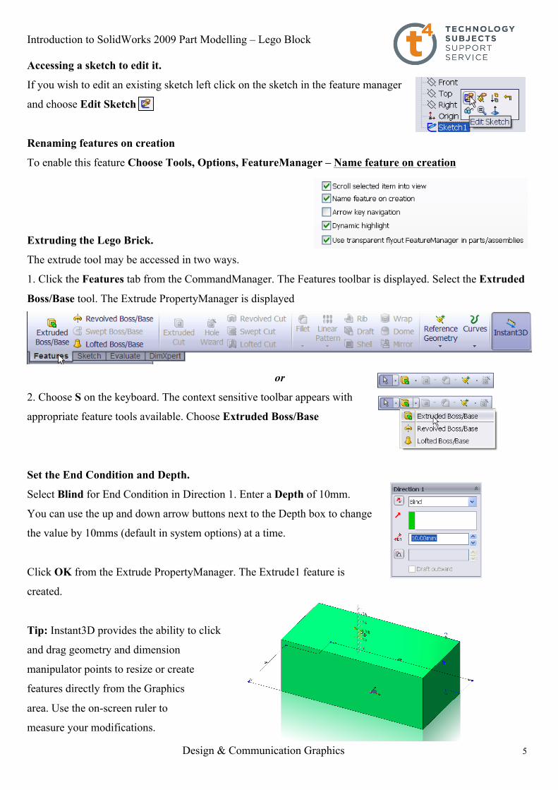
Accessing a sketch to edit it.
If you wish to edit an existing sketch left click on the sketch in the feature manager
and choose Edit Sketch
Renaming features on creation
To enable this feature Choose Tools, Options, FeatureManager – Name feature on creation
Extruding the Lego Brick.
The extrude tool may be accessed in two ways.
1. Click the Features tab from the CommandManager. The Features toolbar is displayed. Select the Extruded
Boss/Base tool. The Extrude PropertyManager is displayed
or
2. Choose S on the keyboard. The context sensitive toolbar appears with
appropriate feature tools available. Choose Extruded Boss/Base
Set the End Condition and Depth.
Select Blind for End Condition in Direction 1. Enter a Depth of 10mm.
You can use the up and down arrow buttons next to the Depth box to change
the value by 10mms (default in system options) at a time.
Click OK from the Extrude PropertyManager. The Extrude1 feature is
created.
Tip: Instant3D provides the ability to click
and drag geometry and dimension
manipulator points to resize or create
features directly from the Graphics
area. Use the on-screen ruler to
measure your modifications.

Introduction to SolidWorks 2009 Part Modelling – Lego Block
Design & Communication Graphics 6
Using Instant3D
Double click on the top surface of the model. An arrow will appear pointing upwards.
Click and hold the tip of the arrow with the left hand mouse button. Drag the cursor, a ruler will appear. Move
the cursor over the ruler and drag the cursor to change the Depth of the extrude in realtime. Press Esc to exit
Instant3D and record the changes.
Note: Ensure Instant 3D is enabled on the Features toolbar.
Note: Return the Depth of Extrude1 to 10mm to continue with the exercise.
Saving Your Work
Save the part document as Lego Brick.sldprt.
You can save your files as often as you wish. However, there are really only two
situations that require you to save your work:
• After you have done something you want to keep.
• Before you try something that you are not sure will work.
Note: A file saved in a later version of SolidWorks cannot be opened in an earlier version i.e. A
SolidWorks model created in SW2008 cannot be opened in SW2006.
Shell feature
To create a wall thickness of 1mm we use the shell command. The shell command may be chosen from the
commandmanager by selecting the features tab or by using the S key on the keyboard
Note: When the S key is chosen the pop-up toolbar does not contain the shell command. However, the button
may be added by right clicking on the toolbar and choose customise.
Choose the features category and drag the shell command
to the toolbar.
The shell command will appear on the pop-up toolbar
each time it is activated from then on.
Enabled Disabled

Introduction to SolidWorks 2009 Part Modelling – Lego Block
Design & Communication Graphics 7
Insert 1mm as thickness value for the walls
of the Brick.
Choose the underneath of the Brick as
Faces to remove.
Choose OK.
Choose Isometric from the Heads-up View toolbar
Creating the cylindrical boss.
Right-click the top face of the Lego Brick. The top face is the
Sketch plane and is highlighted in the Graphics area.
Click the Sketch tool from the Context toolbar.
Choose Normal to from the heads up toolbar
Choose Hidden Lines Visible from the heads up toolbar.

Introduction to SolidWorks 2009 Part Modelling – Lego Block
Design & Communication Graphics 8
Sketch a circle.
Click the Circle tool from the pop-up toolbar.
Circle PropertyManager is displayed.
Add the sketch as shown.
Add the tangent relations between the circle and the
hidden detail edges as shown.
Smart dimension the circle to fully define the sketch.
Choose Shaded with Edges and Isometric from the heads up toolbar. Exit the sketch
Using Instant3D to create the Extruded Boss/Base
Click on the sketch in the graphics area, an arrow appears as shown.
Click and drag the arrow, as described earlier, to a
Depth of 1.6mm.
Press Esc to exit Instant3D. Extrude 2 is created
in the FeatureManager.

Introduction to SolidWorks 2009 Part Modelling – Lego Block
Design & Communication Graphics 9
Tesselation
The display of geometry on your system may appear somewhat different from the illustrations. The lines may
appear rougher. This is called tessellation. Tesselation or line display is related to the performance of the
computer. Higher quality graphics or higher system settings will improve model appearance.
Choose Tools, Options, Document Properties. Image Quality…
Inserting a Fillet Feature
The Fillet feature rounds sharp edges and faces. We will use the Fillet feature to round the sharp edges of the
Lego Brick. The Fillet feature requires an edge or face with a specified radius.
In general, it is best to follow these few rules when inserting a fillet:
1. Add larger fillets before smaller ones. When several fillets converge at a vertex, create the larger fillets
first.
2. Add drafts before fillets. If you are creating a molded or cast part with many filleted edges and drafted
surfaces, in most cases you should add the draft features before the fillets.
3. Save cosmetic fillets for last. Try to add cosmetic fillets after most other geometry is in place. If you add
them earlier, it will take longer to rebuild the part.
Choose Fillet from the Pop-up toolbar
Two PropertyManager tabs are available:
1. Manual. Use this tab to maintain control at the feature level similar to the
use of fillet command in SW2006.
2. FilletXpert. Use this tab when you want the SolidWorks software to manage
the structure of the underlying features for a constant radius fillet.
Fillet / FilletXpert PropertyManager
The FilletXpert PropertyManager is displayed when you click the FilletXpert tab
in the Fillet PropertyManager. The FilletXpert manages, organises, and reorders
constant radius fillets. Use the Add tab to create new constant radius fillets.
Use the Change tab to modify existing fillets. Use the Corner tab to create and
manage fillet corner features where exactly three filleted edges meet at a single
vertex.
Introduction to SolidWorks 2009 Part Modelling – Lego Block
Design & Communication Graphics 10
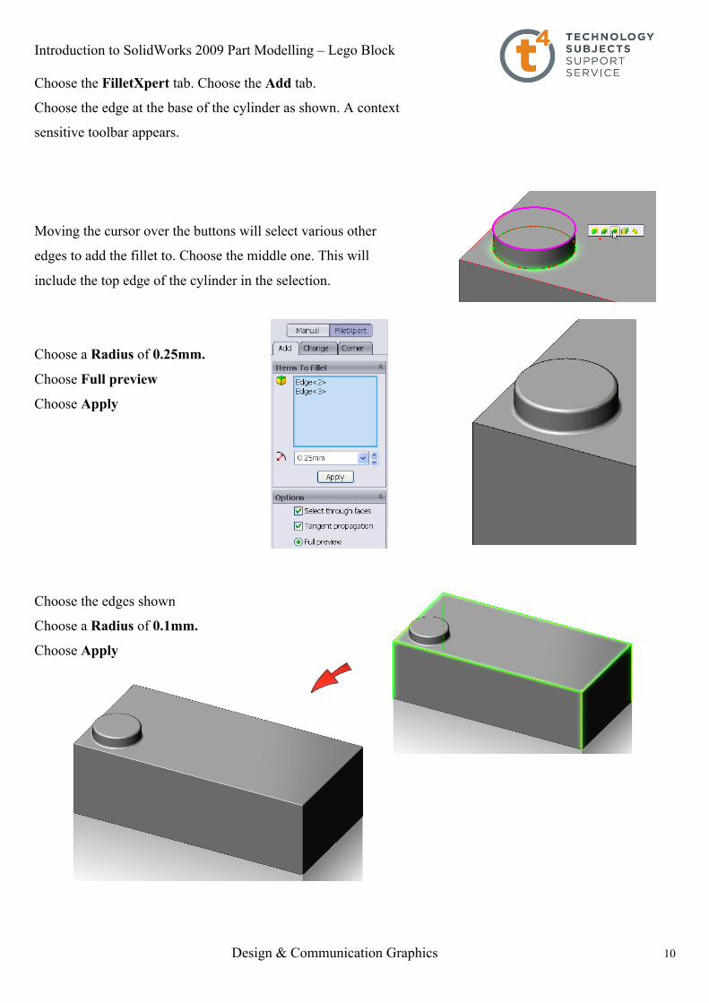
Choose the FilletXpert tab. Choose the Add tab.
Choose the edge at the base of the cylinder as shown. A context
sensitive toolbar appears.
Moving the cursor over the buttons will select various other
edges to add the fillet to. Choose the middle one. This will
include the top edge of the cylinder in the selection.
Choose a Radius of 0.25mm.
Choose Full preview
Choose Apply
Choose the edges shown
Choose a Radius of 0.1mm.
Choose Apply

Introduction to SolidWorks 2009 Part Modelling – Lego Block
Design & Communication Graphics 11
Editing Extrude2 feature using Instant3D
When modeling we commonly need to change features as we progress through the modeling stage.
To demonstrate the simplicity with which we can edit features using Instant3D we will edit the height of
Extrude2.
Double click on the top face of Extrude2.
The arrow used to create the feature appears along
with the Depth dimension of 1.6mm.
You may click and drag the arrow along the ruler, as
Before, to change the feature Depth to 2mm
or
Click on the circle on the extension line of the 1.6mm dimension.
Hold and drag the dimension along the ruler to a depth of 2mm.
Press Esc to exit.
Adding “LEGO” text to the cylindrical face.
Select the top face of the cylinder and choose Sketch
Choose Normal to from the heads up toolbar.
Choose Centreline from the context sensitive shortcut toolbar
Create the sketch shown ensuring to capture the automatic relations
Choose Text from the Sketch tab in the commandmanager.
Choose the centerline as the text guide curve
Enter “LEGO” as the Text.

Introduction to SolidWorks 2009 Part Modelling – Lego Block
Design & Communication Graphics 12
Uncheck “Use document font”. Select
Select Elephant as font type with a height of 1mm. Choose OK.
Choose Centre Align to centre the text on the sketch line.
Select . Exit the sketch as described earlier.
Creating the Extruded Cut
Choose Extruded Cut from the shortcut toolbar.
Choose the LEGO text sketch.
Choose a Blind End Condition to a Depth of 0.1mm
Choose OK
Note: Extruded Cut appears as
Extrude3 in the featuremanager and is
only differentiated from the extruded
boss/base, Extrude2, by its symbol.
- Extruded Boss/Base
- Extruded Cut

Introduction to SolidWorks 2009 Part Modelling – Lego Block
Design & Communication Graphics 13
Pattern feature
The cylindrical feature along with the extruded text and fillets will now be copied to create a further seven
features on the top of the Lego Brick.
Choose Linear Pattern from the feature tab in the commandmanager.
Choose Extrude3, Fillet1
and Extude2 as features
to pattern.
Choose Directions, Number of Instances and Spacing as outlined below.
Choose OK
Adding the features underneath.
Next we will add the features inside the Lego Brick.
These features allow the Bricks to assemble together and are
therefore related to the cylindrical protrusions on the top of
the Brick.
We will create a sketch on the underside of the top surface.
Choose Bottom view from the heads up toolbar.

Introduction to SolidWorks 2009 Part Modelling – Lego Block
Design & Communication Graphics 14
Choose Wireframe from the heads up toolbar.
The cylinders located underneath are located tangential to those on top
and hence the Lego Bricks assemble correctly in relation to one another.
Creating the Sketch
Click on the surface and choose sketch.
From the shortcut toolbar choose Perimeter Circle
Perimeter Circle generates a circle based on three points
defining the circumference of the circle.
Choose the three points, as shown below, ensuring the circle is drawn tangential to the cylinders as shown.
The circle remains blue and has yet to be defined.
Add a Tangential Relation between the circle and each
of the other three circles.
The circle turns black – fully defined.
Introduction to SolidWorks 2009 Part Modelling – Lego Block
Design & Communication Graphics 15
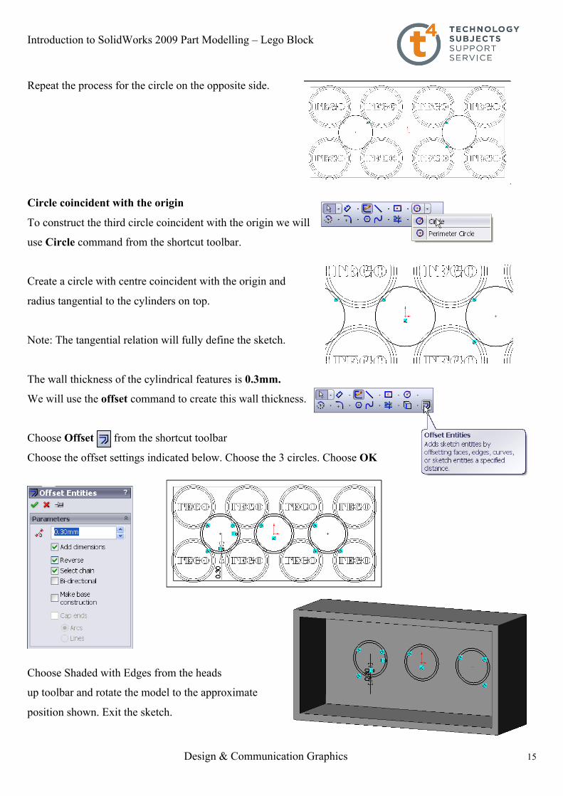
Repeat the process for the circle on the opposite side.
Circle coincident with the origin
To construct the third circle coincident with the origin we will
use Circle command from the shortcut toolbar.
Create a circle with centre coincident with the origin and
radius tangential to the cylinders on top.
Note: The tangential relation will fully define the sketch.
The wall thickness of the cylindrical features is 0.3mm.
We will use the offset command to create this wall thickness.
Choose Offset from the shortcut toolbar
Choose the offset settings indicated below. Choose the 3 circles. Choose OK
Choose Shaded with Edges from the heads
up toolbar and rotate the model to the approximate
position shown. Exit the sketch.
Introduction to SolidWorks 2009 Part Modelling – Lego Block
Design & Communication Graphics 16
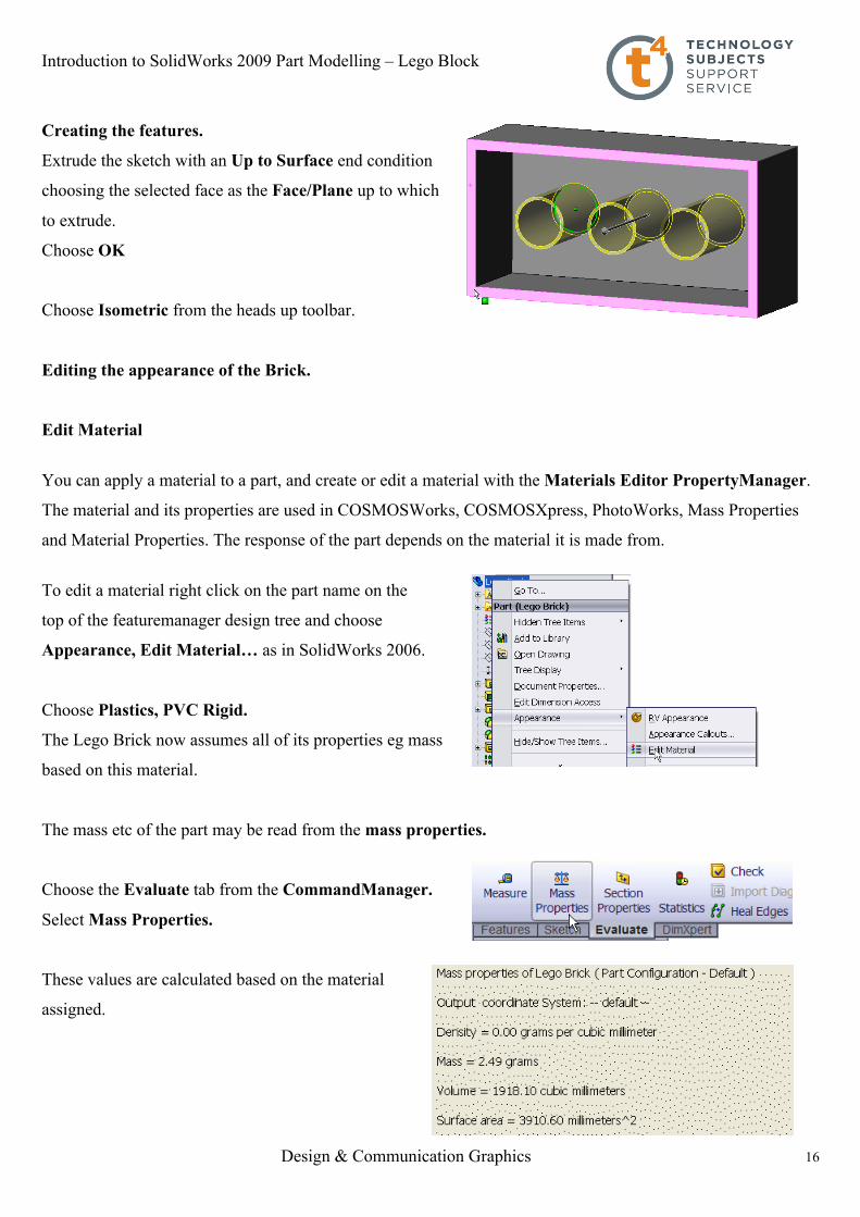
Creating the features.
Extrude the sketch with an Up to Surface end condition
choosing the selected face as the Face/Plane up to which
to extrude.
Choose OK
Choose Isometric from the heads up toolbar.
Editing the appearance of the Brick.
Edit Material
You can apply a material to a part, and create or edit a material with the Materials Editor PropertyManager.
The material and its properties are used in COSMOSWorks, COSMOSXpress, PhotoWorks, Mass Properties
and Material Properties. The response of the part depends on the material it is made from.
To edit a material right click on the part name on the
top of the featuremanager design tree and choose
Appearance, Edit Material… as in SolidWorks 2006.
Choose Plastics, PVC Rigid.
The Lego Brick now assumes all of its properties eg mass
based on this material.
The mass etc of the part may be read from the mass properties.
Choose the Evaluate tab from the CommandManager.
Select Mass Properties.
These values are calculated based on the material
assigned.

Introduction to SolidWorks 2009 Part Modelling – Lego Block
Design & Communication Graphics 17
RealView Graphics
With RealView enabled appearance and scenes may be added to create photorealistic views of a model.
RealView Graphics uses the graphics card to give more advanced shading in real time, when the model is
rotated the rendering is retained.
Once a physical material has been applied RealView Graphics may be used to give the model a realistic
appearance i.e. a steel physical material could be applied to a model, to facilitate physical properties, but it
could then be enhanced with the appearance of glossy paint.
To enable RealView choose View, Display, RealView Graphics…
Note: The symbol used for RealView in 2008 is whereas the symbol used in 2009 is . Some of the
functionality has changed in 2009 and hence we will be approaching the area with 2009 functionality in mind.
However, for the remainder of this exercise when accessing RealView we will refer to the 2008 symbol.
Appearance
Appearances are the likeness of how a material would look without adding the physical properties.
A hierarchy exists when adding appearance to a model;
• Faces override all other instances in a model
• Features override bodies but not faces
• Bodies override documents
By default the model will appear in default plastic
Adding an appearance to the Lego Brick.
Right click on any face of the model and choose
Appearance Callout
(Note: This icon will appear as in SW 2009)
A drop-down menu appears with the various aspects of the model in hierarchical order.
Click on the colour swatch next to the part name, Lego brick.
The RealView/PhotoWorks Tab appears on the right hand side of the screen
and the Colors Appearancemanager on the left as shown overleaf.
A preview window appears to preview the resulting render.

Introduction to SolidWorks 2009 Part Modelling – Lego Block
Design & Communication Graphics 18
Within the RealView/PhotoWorks tab we can access appearances, scenes, decals and lights folders.
Choose Appearances. The categories are listed on top with the various options within each category displayed
below.
Choose Plastic, Medium Gloss, blue medium gloss plastic.
The blue medium gloss plastic is applied to the entire part.
The colour may be changed by choosing from the colour
swatch in the Appearance PropertyManager.
Choose OK
How do I apply a different colour to a face?
Right click on the face and choose Appearance Callout.
In the dropdown menu choose the face option.
Follow the same procedure as before for applying the colour.

Introduction to SolidWorks 2009 Part Modelling – Lego Block
Design & Communication Graphics 19
Adding a scene
Document scene backgrounds are used to enhance appearances. Scenes are made up of a background and the
addition of lighting. Within the task pane scenes are placed in three categories; Basic, Studio and Presentation.
Note: Earlier in the exercise we changed the background to plain white.
We checked use plain background colour as opposed to the
document scene background. Whilst this remains checked we cannot
use the available scenes.
Choose Options, System Options, Colors…
and select Use document scene background as opposed to plain.
The default scene “Light Cards” will now be displayed.
To view the various scenes choose from the task pane. Choose Scenes.
Double click on any of the folder categories to display a preview of the various
scenes within that category
Drag and drop the chosen scene from the task pane into the graphics area.
The background updates immediately to reflect the changes.
Investigate the various scenes available within the various categories by
dragging and dropping them into the graphics area.
These scenes may also be
accessed, without preview,
under Apply scene on
the heads up toolbar

Introduction to SolidWorks 2009 Part Modelling – Lego Block
Design & Communication Graphics 20
Note: A plain white background is available in the basic scenes folder,
to facilitate screen grabs, saving as a jpeg etc.
Creating a drawing
SolidWorks allows you to create drawings from parts or assemblies. These drawings are fully associative with
the parts and assemblies they reference. If dimension is changed on the finished drawing, that change
propagates back to the model. Likewise, if the model is changed, the drawing updates automatically.
Drawings communicate three things about the objects they represent:
• Shape – Views communicate the shape of an object.
• Size – Dimensions communicate the size of an object.
• Other information – Notes communicate nongraphic information about manufacturing processes such
as drill, ream, bore, paint, plate, grind, heat treatment, remove burrs, and so forth.
Select New, Make Drawing from Part/Assembly, from the standard toolbar.
Choose the DCG A3L template from the available list.
The Drawing document is opened with the DCG A3L
template displayed.
Note: To change the drawing paper to plain white choose;
Tools, Options, Colors, Drawings Paper Color
Select Edit and choose White. Choose OK.
Select Use specified color for drawings paper color
Choose OK
The drawing sheet will now be plain white.
Introduction to SolidWorks 2009 Part Modelling – Lego Block
Design & Communication Graphics 21
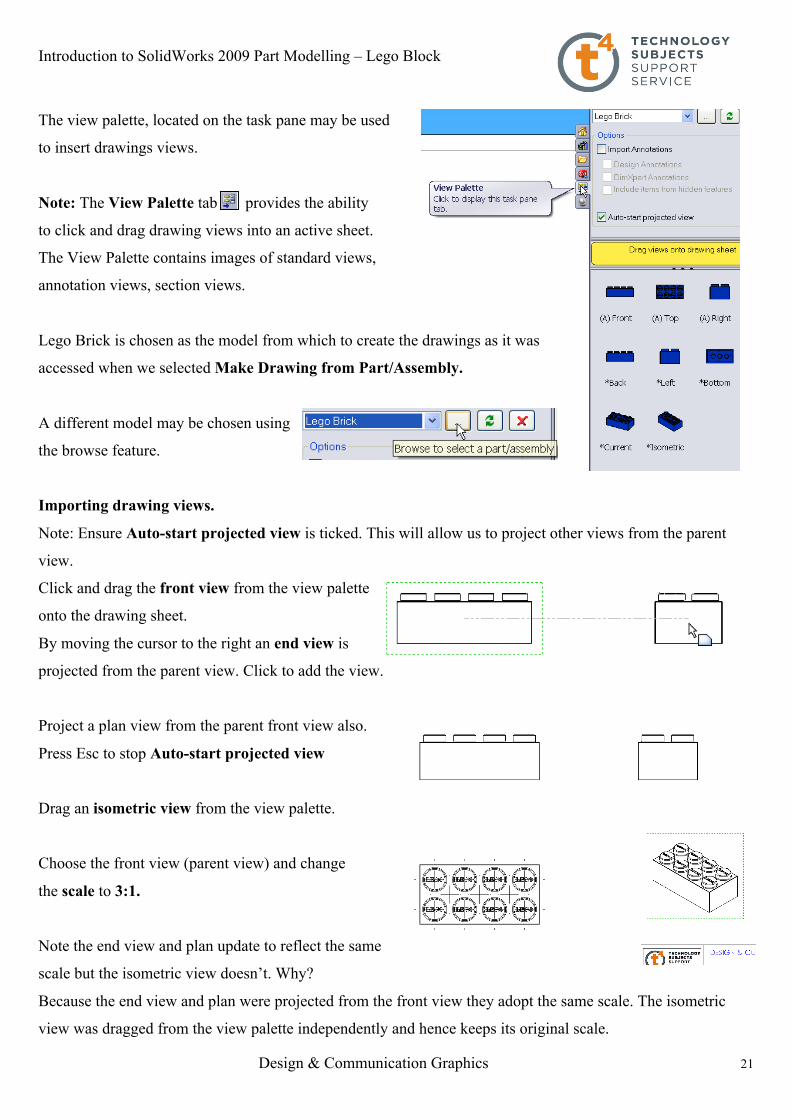
The view palette, located on the task pane may be used
to insert drawings views.
Note: The View Palette tab provides the ability
to click and drag drawing views into an active sheet.
The View Palette contains images of standard views,
annotation views, section views.
Lego Brick is chosen as the model from which to create the drawings as it was
accessed when we selected Make Drawing from Part/Assembly.
A different model may be chosen using
the browse feature.
Importing drawing views.
Note: Ensure Auto-start projected view is ticked. This will allow us to project other views from the parent
view.
Click and drag the front view from the view palette
onto the drawing sheet.
By moving the cursor to the right an end view is
projected from the parent view. Click to add the view.
Project a plan view from the parent front view also.
Press Esc to stop Auto-start projected view
Drag an isometric view from the view palette.
Choose the front view (parent view) and change
the scale to 3:1.
Note the end view and plan update to reflect the same
scale but the isometric view doesn’t. Why?
Because the end view and plan were projected from the front view they adopt the same scale. The isometric
view was dragged from the view palette independently and hence keeps its original scale.

Introduction to SolidWorks 2009 Part Modelling – Lego Block
Design & Communication Graphics 22
Note: When the views are dragged from the view palette they disappear
from it and are no longer available.
Adding dimensions
Choose Model Items from the annotations tab
of the commandmanager
Choose the settings shown across. Choose OK
Drag the dimensions into the desired positions. Use Smart Dimension
from the Annotation tab to add futher dimensions if required.
Note The context sensitive toolbar may be accessed within the drawing
environment at any stage by pressing S on the keyboard.