Introduction to Soil Mechanics Civil 270 Part 2
173
FOUNDATION ENGINEERING IV B.Tech II semester Regulation: IARE R-16 BY Mr.N.VENKAT RAO Assistant professors U.Deepthi, V.Alivelu Manga DEPARTMENT OF CIVIL ENGINEERING INSTITUTE OF AERONAUTICAL ENGINEERING (Autonomous) DUNDIGAL, HYDERABAD - 500 043 1
Transcript of Introduction to Soil Mechanics Civil 270 Part 2

FOUNDATION ENGINEERINGIV B.Tech II semester
Regulation: IARE R-16
BY Mr.N.VENKAT RAO
Assistant professorsU.Deepthi, V.Alivelu Manga
DEPARTMENT OF CIVIL ENGINEERINGINSTITUTE OF AERONAUTICAL ENGINEERING
(Autonomous)DUNDIGAL, HYDERABAD - 500 043
1

CO’s Course outcomes
CO 1Understand the need and various methods of soil exploration, planning and preparation of soil investigation report
CO 2 Analyze the stability of slopes by various methods
CO 3 Understand various earth pressure theories and stability of retaining walls at various conditions
CO 4 Understand shallow and deep foundations according to various bearing capacity theories and analyze Pile foundations in various different soils
CO 5 Understand various shapes and components of wells and analyze, design according to IRC guidelines
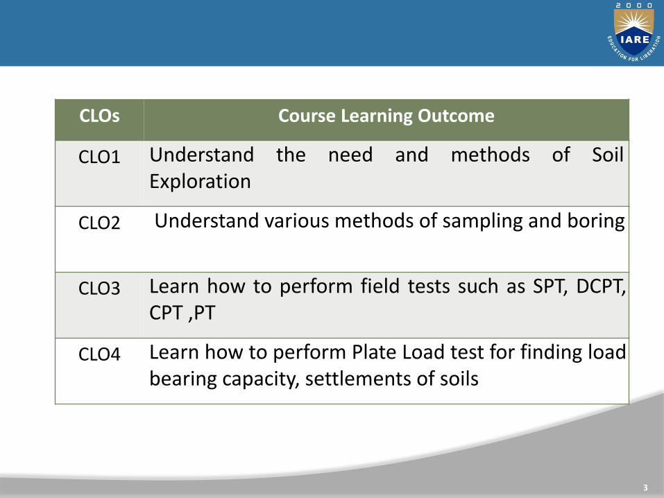
CLOs Course Learning Outcome
CLO1 Understand the need and methods of SoilExploration
CLO2 Understand various methods of sampling and boring
CLO3 Learn how to perform field tests such as SPT, DCPT,CPT ,PT
CLO4 Learn how to perform Plate Load test for finding loadbearing capacity, settlements of soils
3

CLOs Course Learning Outcome
CLO5 Learn how to perform in-situ test using pressuremeter
CLO6 Understand the importance of geophysical methods
CLO7 Learn how to prepare Soil investigation Report
4

UNIT-ISOIL EXPLORATION
5

SUB SOIL EXPLORATION
6
• The process of collection soil data for the assessment soilproperties at a site through series of laboratory and fieldinvestigation is collectively called Sub-soil Exploration
• Enables the engineers to draw soil profile indicating thesequence of soil strata and the properties of soil involved.

COMMON STAGES IN SITE INVESTIGATION
7
• Desk Study
• Site Reconnaissance
• Field Investigations
• a) Preliminary Ground Investigation
• b) Detailed Ground Investigation
• Laboratory Testing
• Report Writing
• Follow up Investigations during design &construction
• Appraisal of performance

PURPOSE OF SOIL INVESTIGATION
8
Site investigation provides first hand information for• Selection of foundation type.• Design of foundations.• Contractors to quote realistic and competitive tenders.• Planning construction techniques.• Selection of appropriate construction equipment (especially
for excavation and foundations).• Feasibility studies of the site.• Estimating development cost for the site.• Study of environmental impacts of the proposed
construction.

METHODS OF SOIL EXPLORATION
9

The methods to determine the sequence, thickness and lateralextent of the soil strata and where appropriate the level ofbedrock.The common methods include
Test pitsShafts and auditsBoring or drilling
10
METHODS OF INVESTIGATION

TEST PITS
11
The excavation of test pits is a simple and reliable method.• The depth is limited to 4-5m only.• The in-situ conditions are examined visually• It is easy to obtain disturbed and undisturbed samples
• Block samples can be cut by hand tools and tube samples can
be taken from the bottom of the pit.

To identify the groundwater conditions.
12
oAuger boring
Percussion boring
BORING OR DRILLING
• Boring refers to advancing a hole in the ground.
• Boring is required for the following
• To obtain representative soil and rock samples for laboratorytests.
• Performance of in-situ tests to assess appropriate soilcharacteristics. Some of the common types of boring are asfollows
• Auger boring
• Wash boring
• Rotary drilling
• Core drilling
• Percussion drilling

AUGER BORING
• Hand Auger
• Mechanical Auger• It is the simplest method of boring used for small
projects in soft cohesive soils.• For hard soil and soil containing gravels boring with
hand auger becomes difficult.
• Hand-auger holes can be made up to about 20m depth, although depth greater than about 8-10m is usually not practical.
13

HANDAUGER
14
• The length of the auger blade varies from 0.3-0.5m.
• The auger is rotated until it is full of soil, then it is with drawn to remove the soil and the soil type present at various depths is noted.
• Repeated with drawl of auger for soil removal makes boringdifficult below 8-10m depth.
• The soil samples collected in this manner are disturbedsamples and can be used for classification test.
• Auger boring may not be possible in very soft clay orcoarse and because the hole tends to collapse when auger isremoved
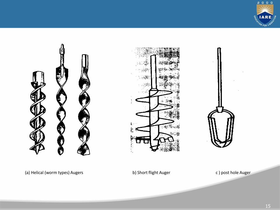
(a) Helical (worm types) Augers ( b) Short flight Auger ( c ) post hole Auger
b c
15
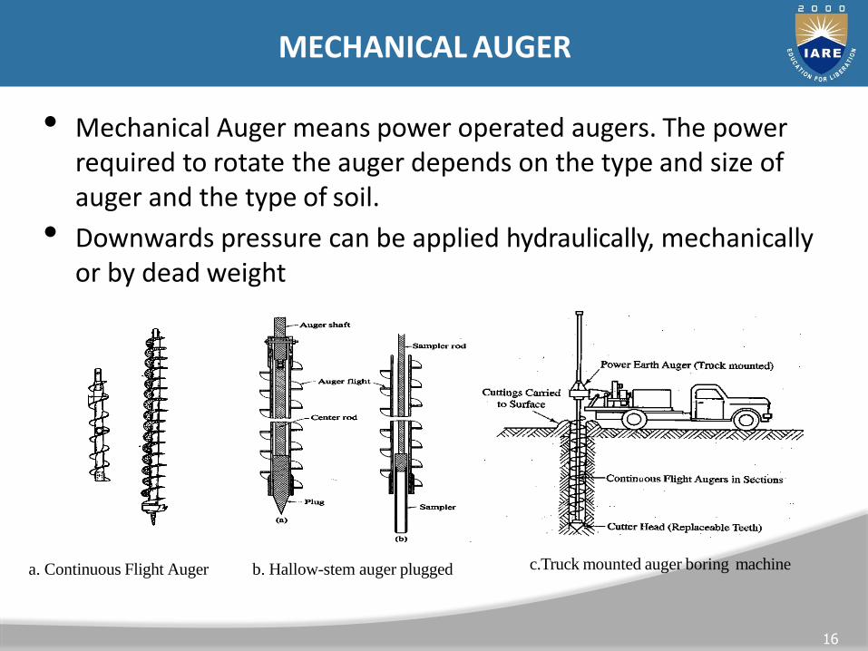
MECHANICAL AUGER
• Mechanical Auger means power operated augers. The power required to rotate the auger depends on the type and size of auger and the type of soil.
• Downwards pressure can be applied hydraulically, mechanically or by dead weight
a
b
c
d
16
a. Continuous Flight Auger b. Hallow-stem auger plugged c.Truck mounted auger boring machine

• The diameter of the flight auger usually is between 75 to300mm,although diameters up to 1m and bucket augers up to2m are available.• Borehole depths up to 50m are possible with
continuous-flightaugers.•The most common method is to use continuous flight augers.Continuous flight augers can be solid stem or hollow stem withinternal diameter of 75-150mm.
17

WASH BORING
18
• Water with high pressure pumped through hallow boringrods is released from narrow holes in a chisel attach to thelower end of the rods.
• The soil is loosened and broken by the water jet and the up-down moment of the chisel.
• The soil particles are carried in suspension to the surfacebetween the rock and the borehole sites.
• The rods are raised and drop for chopping action of thechisel by means of winch.
• Wash boring can be used in most type of soil but theprogress is slow in coarse gravel strata.

• The accurate identification of soil strata is difficult due tomixing of the material has they are carried to the surface.
• The method is unacceptable for obtaining soil samples.
• It is only used for advancing the borehole to enable tubesample to be taken or field test to be carried at the holebottom.
• The advantage is that the soil immediately below the holeremains relatively un-disturbed
19

GEOPHYSICAL METHODS
20
Electromagnetic Wave Techniques
• Ground Penetrating Radar(GPR)
• Electromagnetic Conductivity (EM)
• Surface Resistivity (SR)
• Magnetometer Surveys (MT)
Mechanical Wave Measurements
• Crosshole Tests (CHT)
• Downhole Tests (DHT)
• Spectral Analysis of Surface Waves
• Seismic Refraction

How Many Borings & How Deep?
• NO hard-and-fast rule exists for determining thenumber of borings or the depth to which borings areto be advanced.
21
FIELD EXPLORATION

Conventional Wisdom
The number (density) of borings will increase
• As soil variability increases
• As the loads increase
• For more critical/significant structures
Rules of Thumb
• Soft Soils - Space 30 to 60 m
• As soils become harder, spacing may beincreased up to 150m
22
HOW MANY BORINGS?

Source: Sowers 1979
23
Structure or Project
Subsurface Variability
Spacing of Borings (m)
Highway Subgrade
Irregular 50
Average 150
Uniform 300
Multistory Building
Irregular 15
Average 30
Uniform 45
HOW MANY BORINGS?

24
HOW MANY BORINGS?

HOW DEEP?
25

SOIL BORING
26

DISTURBED VS UNDISTURBED
Good quality samples necessary.
AR<10%
soi
l
100(%)I.D.2
O.D.2 − I.D.2
AR=
area
ratiosampling tube
Thicker the wall, greater the disturbance.
27

DISTURBED VS UNDISTURBED
28

SHELBY TUBE SAMPLER
• Suitable for SOIL
• Thin-wall Steel Tubes
• 3.0" OD, 2.875" ID, 30.0" long
29

42
COMMON SAMPLING METHODS

GROUND WATER
• Piezometers
• Monitor Wells & Sampling
• Permeability Tests
31

IN-SITU TESTING
32
• When it is difficult to obtain ―undisturbed‖ samples
• Cohesionless soils, Sensitive clays
• In-situ Test Methods
Standard Penetration Test (SPT)
Cone Penetration Test (CPT)
Vane Shear Test (VST)
Texas Cone Penetration Test(TCP)

STANDARD PENETRATION TEST (SPT)
33
65 kg Hammer
75 cm free fall
Drive sampler over 150 mm
Recordno.ofblows per
each 150 mmpenetration
oSPT blow count=blows2nd
3rd
150 mm
150 mm
for
penetration + blows for
penetration

STANDARD PENETRATION TEST (SPT)
34

TYPES OF SPT HAMMERS
35

CORRECTIONS TO SPT BLOW COUNTS
36
Factors affecting SPT blow count are
▪ Hammer Efficiency
▪ Borehole diameter
▪ Type of sampler
▪ Rod length
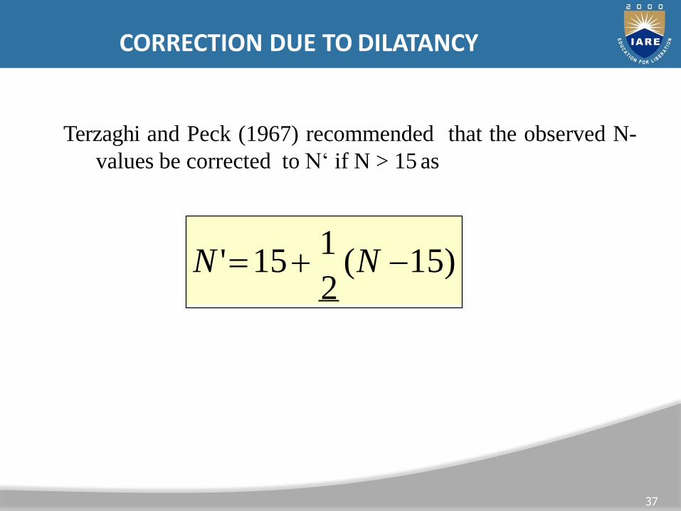
CORRECTION DUE TO DILATANCY
N '=15+1
(N −15) 2
37
Terzaghi and Peck (1967) recommended that the observed N-
values be corrected to N‘ if N > 15 as

OVERBURDEN CORRECTION
0N '= 0.77 log 10(
2000) . N
Peck, Hanson and Thornburn (1974)
38
IS:2131-1981 recommend that the correction due to
overburden shall be applied first.

PRESSUREMETER
Test
The borehole pressure meter test is an in situ test where a carefully prepared borehole that is
sufficiently—but not over about 10 percent—oversized is used. The pressure meter probe consisting
of three parts (top, cell, and bottom) as shown in figure above is then inserted and expanded to and
then into the soil. The top and bottom guard cells are expanded to reduce end-condition effects on the
middle (the cell) part, which is used to obtain the volume versus cell pressure relationship used in
data reduction.39

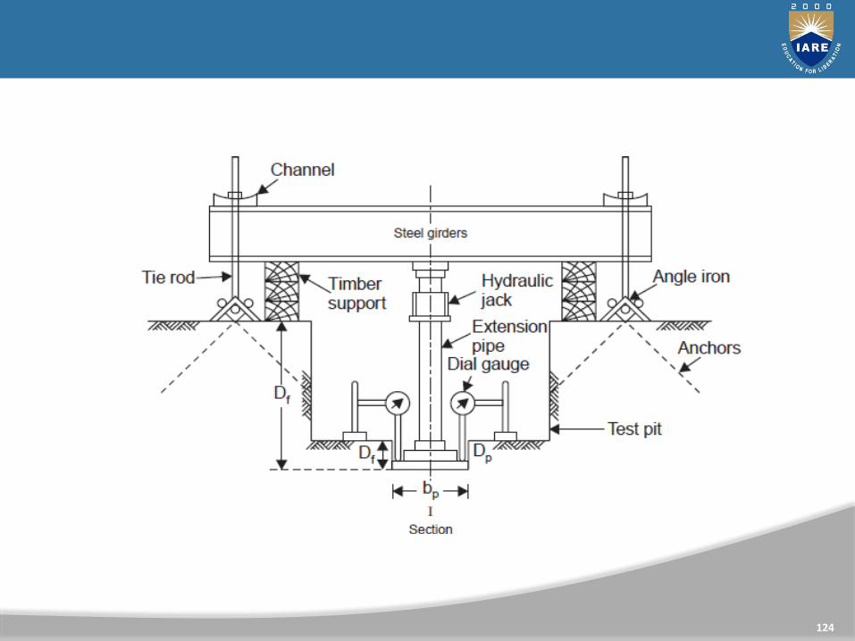
THE PLATE LOAD TEST (PLT)
40

41
REQUIRED INFORMATION
• Drilling & Sampling Depths & Methods
• Field Test Data
• Drilling Notes
• Soil appearance, stratification
• Acomplete record
• Pass/Fail
...”

PREPARATION OF BORING LOGS
42
1. Name and address of the drilling company2. Driller‘s name3. Job description and number4. Number, type, and location of boring5. Date of boring6. Subsurface stratification, which can he obtained by visual
observation of the soil brought out by auger, split-spoon sampler,and thin-walled Shelby tube sampler
7. Elevation of water table and date observed, use of casing and mud losses, and so on
8. Standard penetration resistance and the depth ofSPT9. Number, type, and depth of soil sample collected10.In case of rock coring, type of core barrel used and, for each run,
the actual length of coring, length of core recovery, and RQD

43

UNIT-IISLOPE STABILITY
44

CLOs Course Learning Outcome
CLO8 Understand basic concepts of earth slopes
CLO9 Analyse failure of infinite slopes
CLO10 Analyse types of failures for finite slopes
CLO11 Learn how to find Stability of slopes by Swedish arcMethod
45

CLOs Course Learning Outcome
CLO12 Learn how to find Stability of slopes by Method ofSlices for slopes
CLO13 Find Stability of slopes by Taylor’s Stability number
CLO14 Understand basic concepts of Stability of slopes ofearth dam under different conditions
46

THE AIMS OF SLOPE STABILITY ANALYSIS
47
• To understand the development and form of natural slopes
and the processes responsible for different natural features.
• To assess the stability of slopes under short-term (often
during construction) and long-term conditions.
• To assess the possibility of landslides involving natural or
existing engineered slopes.
• To analyze landslides and to understand failure mechanisms and
the influence of environmental factors.
• To enable the redesign of failed slopes and the planning and
• design of preventive and remedial measures, where necessary.
• To study the effect of seismic loadings on slopes and
embankments.

SLOPES OF EARTH ARE OF TWO TYPES
48
• Natural slopes: slopes exist in hilly areas• Man made slopes:
– The sides of cuttings
– The slopes of embankments constructed for roads railway lines, canals etc.
– The slopes of earth dams constructed for storing water.

THE SLOPES WHETHER NATURAL OR ARTIFICIAL MAY BE
49
Infinite slopes
The term infinite slope is used to designate a
• constant slope of infinite extent.
• The long slope of the face of a mountain
Finite slopes
• Finite slopes are limited in extent.
• The slopes of embankments and earth dams are examples of finite slopes

CAUSES OF FAILURE OF SLOPES
50
• Gravitational force
• Force due to seepage water
• Erosion of the surface of slopes due to flowing water
• The sudden lowering of water adjacent to a slope
• Forces due to earthquakes

FORCES THAT ACT ON EARTH SLOPES
51

52
FORCES THAT ACT ON EARTH SLOPES

TYPES OF SLOPE FAILURES

SHALLOW SLOPE FAILURE
Toe circle / slope circle Base failure
Modes of failure of finite slope 54

STABILITY OF FINITE SLOPE (CIRCULAR FAILURESURFACES)
55
ORDINARY METHOD OF SLICES
• The soil above the surface of sliding is divided intoa number of vertical parallel slices. The stability ofeach slice is calculated separately. This is a versatiletechnique (no homogeneity, pwp).
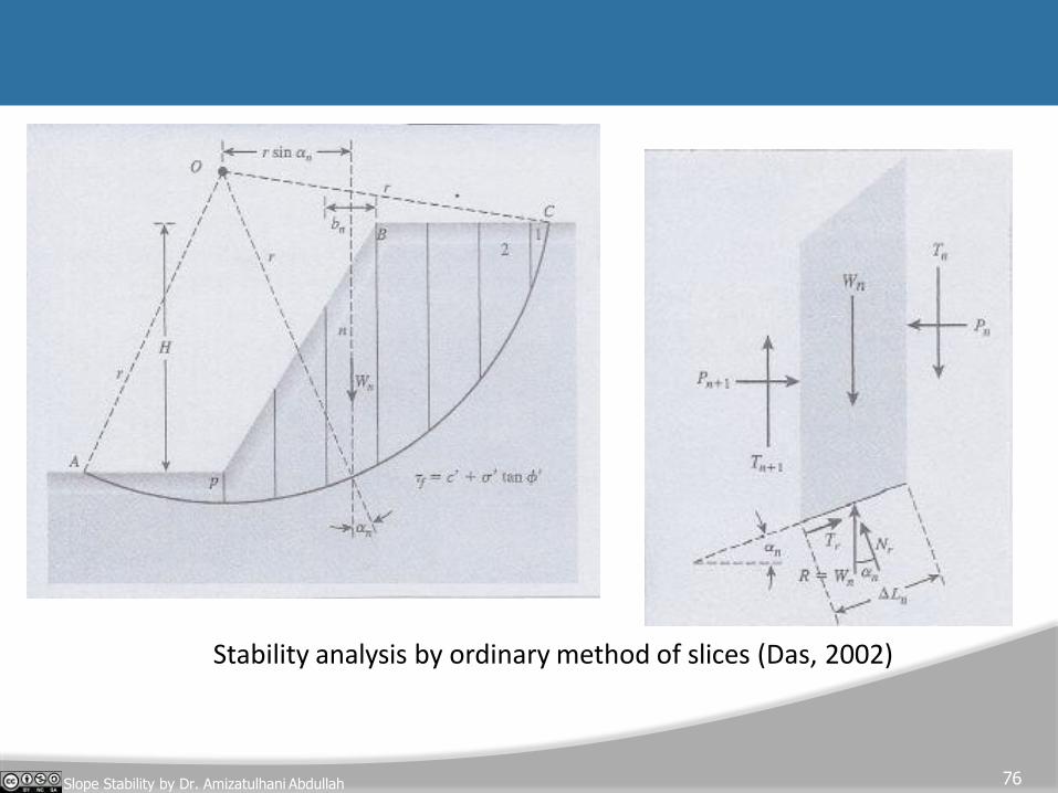
Stability analysis by ordinary method of slices (Das, 2002)
76Slope Stability by Dr. Amizatulhani Abdullah

Procedure
• Draw to scale a cross section of the slope.
• A trial curved surface along which sliding is assumed to take place is drawn.
• The trial surface is normally approximately circular.
• Soil between the trial surface and the slope isthen divided into a number of vertical slices ofequal width.
57

Weight of soil within each slice = Slice volume x Soil unit weight
• Noted as W.
• Can be resolved into two component ;
i) component of W normal to the base, Wn and
ii) component of W parallel to the base, Wp
• It is the parallel component that tends to cause sliding.
• Resisting to sliding is afforded by the soil‘s cohesion and
internal friction.
Cohesion force = Soil cohesion x Length of the slice
Friction force = Wn x Friction coefficient, tan
58

APPLY VALUE INTO FORMULA
59
n= p
n= p
sF = n=1
Wn sinn
n=1
(cLn +Wn cosn tan)

where m = Stability number
d
60
d
f
sc c
=cu
F =
• The corresponding circle that gives the lowestFOS
value is called critical circle.
• Fellenius (1927( and Taylor (1937) suggestedthat
(for critical circle case) :
cd = mH

61

TAYLOR’S STABILITY CHART
• Taylor proposed stability coefficients for the analysis of homogeneous slopes.
= m
62
c'
H cr
f (, , , ') =
stability number, m can be obtain fromstability charts – Taylor‘s stability number.
Fs = Fc = F
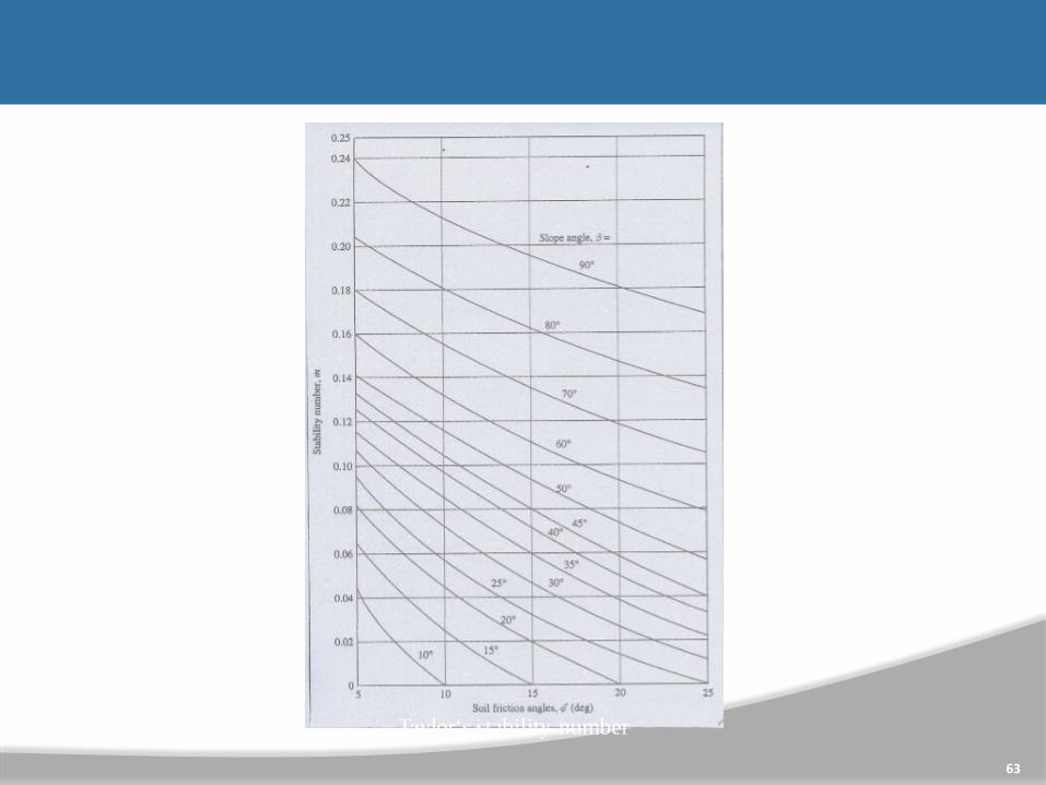
Taylor‘s stability number
63

STABILITY OF FINITE SLOPE
64
BISHOP METHOD OFSLICES
• Bishop proposes a more refined solution to previousmethod where the effect of forces on the sides of eachslice are accounted.
n= p
n
n
sF =
n
n=1
1
W sin sF
m(n )= cosn +
where :

n= p
n n
n= p
n
sF =
n=1
1
W sin
(c'b + Wn tan')m
s
65
F
tan'sinnm(n )= cosn +
where :
Bishop‘s simplified method of slices (Das, 2002)

• Several number of failure surface must beinvestigated so that the critical surface(yields thelowest FOS value) can be found.This method gives satisfactory results in most cases
when programs Widely used.
66
incorporated into computer.

UNIT-IIIEARTH PRESSURE THEORIES
67

CLOs Course Learning Outcome
CLO15 Understand concepts of earth pressure theories forstability of Retaining walls
CLO16 Calculate active and passive earth pressures fromRankine’s earth pressure theories
CLO17 Calculate active and passive earth pressures fromCoulomb’s &Culmann’s Method
CLO18 Asses the stability of retaining wall againstoverturning, sliding, bearing capacity
68
EARTH PRESSURE AT REST
69
GL
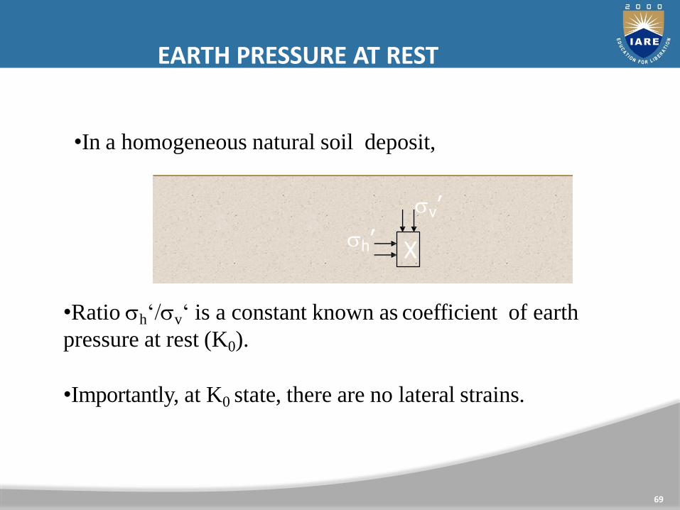
•In a homogeneous natural soil deposit,
X
v’
h’
•Ratio h‘/v‘ is a constant known as coefficient of earth
pressure at rest (K0).
•Importantly, at K0 state, there are no lateral strains.

ESTIMATING K0
70
normally consolidated clays and granular soils,
K0 = 1 – sin ‘
For overconsolidated clays,
K0,overconsolidated = K0,normally consolidated OCR0.5
From elastic analysis
1−0

ACTIVE/PASSIVE EARTH PRESSURES
71
- in granular soils
Wall moves
away from soil
Wall moves
towards soil
A
B
smooth wall
Let‘s look at the soil elements A and B during the
wall movement.

ACTIVE EARTH PRESSURE
72
- in granular soils
A
v‘
h‘
z
v‘ = z
Initially, there is no lateral movement.
h‘ = K0 v‘ = K0z
As the wall moves away from the soil,
v‘ remains the same; and
h‘ decreases till failure occurs.
Active state

ACTIVE EARTH PRESSURE
73
v’
decreasing h‘
Initially (K0 state)
Failure (Active state)
- in granular soils
As the wall moves away from the soil,
active earth
pressure

ACTIVE EARTH PRESSURE
74
- in granular soils
v‘[h‘]active
[h ' ]active = KA v '
1+ sinA
K =1− sin
= tan2 (45− / 2)
Rankine‘s coefficient of
active earth pressure
WJM Rankine
(1820-1872)

75
granular soils
v‘[h‘]active
A
v‘
h‘45 +/2
90+
Failure plane is at
45 + /2 to horizontal
Active Earth Pressure

ACTIVE EARTH PRESSURE
76
A
v’
h’
z
in granular soils As the wall moves away from the soil,
h‘ decreases till failure occurs.
wall movement
h’
Active state
K0 state

ACTIVE EARTH PRESSURE
77
- in cohesive soils
Follow the same steps as
for granular soils. Only
difference is that c 0.
[h ' ]active = KA v '−2c KA
Everything else the same
as for granular soils.
PASSIVE EARTH PRESSURE
78
B
v’
h’
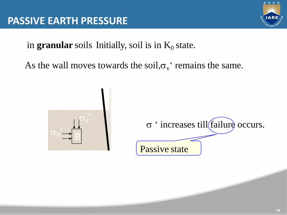
in granular soils Initially, soil is in K0 state.
As the wall moves towards the soil,v‘ remains the same.
h ‘ increases till failure occurs.
Passive state

79
- in granular soils
[h‘]active
h
KAHKPh
H
PA=0.5 KAH2
PP=0.5 KPh2
PA and PP are the
resultant active and
passive thrusts on
the wall
[h‘]passive
Earth Pressure Distribution

80

RANKINE‘S EARTH PRESSURE THEORY
81
[h ' ]active = KA v '−2c KA
[h ' ]passive = KP v '+2c KP
❑ Assumes smooth wall
❑ Applicable only on vertical walls

COULOMB'S EARTH PRESSURE THEORY FOR SAND- ACTIVE STATE
82

83

84

COULOMB'S EARTH PRESSURE THEORY FOR SAND- PASSIVE STATE
85
COLOUMB EARTH PRESSURE THEORY FOR SAND

COULOMB'S EARTH PRESSURE THEORY FOR SAND- PASSIVE STATE
86

87

11788

COULOMB WEDGE ANALYSIS IN CU, FU=0 SOIL
89
Depth of tension crack
The total active thrust is the integration of equation of pa within the limits
of 0-(H-zo)

90

91

RETAINING WALLS - APPLICATIONS
92
highway

RETAINING WALLS - APPLICATIONS
93
basement wall
High-rise building

.
94

95

96
97

GRAVITY RETAINING WALLS
98
cement mortarplain concrete or
stone masonry
cobbles
They rely on their self weight to
support the backfill

CANTILEVER RETAINING WALLS
99
They act like vertical cantilever,
fixed to the ground
Reinforced;
smaller section
than gravity
walls

100
DESIGN OF RETAINING WALLS

1
1
2 2
3 3
PA
PA
PPS
Stoe
toeR
Ryy
Safety against overturning about toe
A
101
H
h PP
to be greater
than 2.0

UNIT-IVSHALLOW AND DEEP FOUNDATIONS
102
CLOs Course Learning Outcome
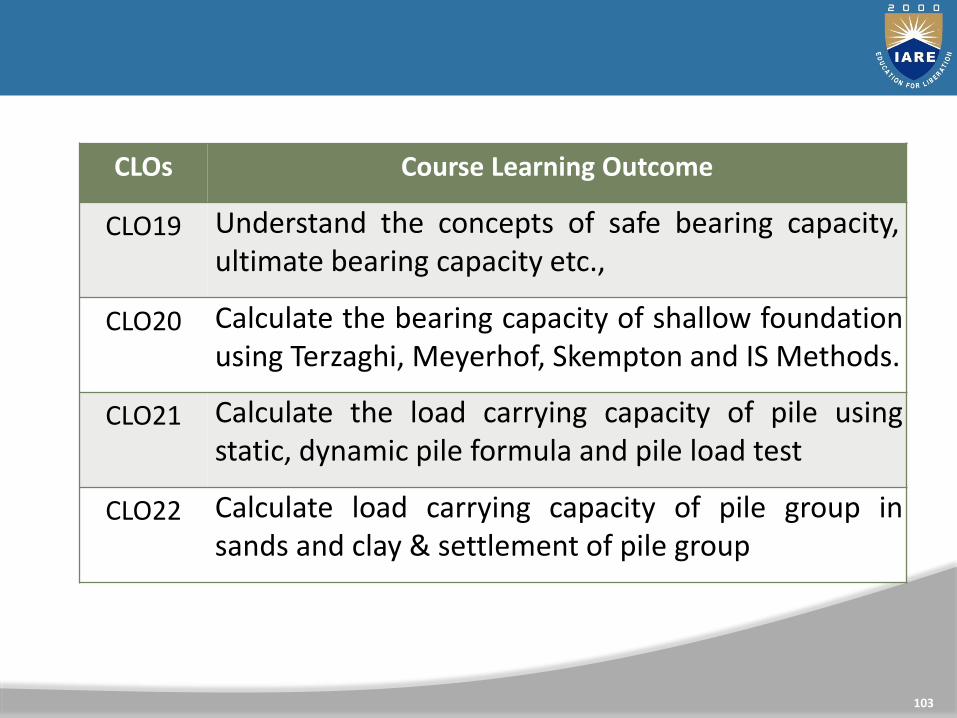
CLO19 Understand the concepts of safe bearing capacity,ultimate bearing capacity etc.,
CLO20 Calculate the bearing capacity of shallow foundationusing Terzaghi, Meyerhof, Skempton and IS Methods.
CLO21 Calculate the load carrying capacity of pile usingstatic, dynamic pile formula and pile load test
CLO22 Calculate load carrying capacity of pile group insands and clay & settlement of pile group
103

FOUNDATION
A Foundation is a integral part of the structure which transfer the load of the superstructure to the soil. A foundation is that member which provides support for the structure and it's loads. It includes the soil and rock of earth's crust and any special part of structure that serves to transmit the load into the rock or soil.

DIFFERENT TYPES OF FOOTINGS
SHALLOW FOUNDATIONS(Df<B)
• STRIP FOOTING
• SPREAD FOOTING
• COMBINE FOOTING
• ISOLATED FOOTING
• RAFT FOOTING
DEEP FOUNDATION (Df>B)
• PILE FOUNDATION
• WELL FOUNDATION

BEARING CAPACITY
106
• Ultimate Bearing capacity: qu
Maximum gross intensity of loading that the soil can supportagainst shear failure is called ultimate bearing capacity.• Net Ultimate Bearing Capacity: qnu
Maximum net intensity of loading that the soil can support at the level of foundation.
qnu = qu - γ Df
• Net Safe Bearing capacity: qns
Maximum net intensity of loading that the soil can safely support without the risk of shear failure.
qns = qnu / FOS

Gross Safe Bearing capacity:
Maximum gross intensity of loading that the soil can safely support without the risk of shear failure
qgs = qns +γDSafe Bearing Pressure:
Maximum net intensity of loading that can be allowed on the soilwithout settlement exceeding the permissible limit.
Allowable Bearing Pressure:
Maximum net intensity of loading that can be allowed on the soilwith no possibility of Minimum of capacity and shear failure orsettlement exceeding the permissible limit.

TYPES OF FAILURES
108

GENERAL SHEAR FAILURE
109
Experiments have shown that foundations on dense sand with RD greater than 70 percent fail suddenly with pronounced peak when settlement reaches about 7 percent of foundation width. This type of failure is seen in dense and stiff soil. The following are some characteristics of general shear failure. Continuous, well defined and distinct failure surface develops between the edge of footing and ground surface. Dense or stiff soil that undergoes low compressibility experiences this failure. Continuous bulging of shear mass adjacent to footing is visible. Failure is accompanied by tilting of footing.

The length of disturbance beyond the edge of footing islarge State of plastic equilibrium is reached initially at the footing edge and spreads gradually downwards andoutwards. General shear failure is accompanied by low strain (<5%) in a soil with considerable ɸ(ɸ>36o) and large N (N > 30) having high relative density(ID > 70%).
ID- Density index or relative density)N- Standard penetration test N value
PUNCHING SHEAR FAILURE
111
This type of failure is seen in loose and soft soil and at deeper
elevations. The following are some characteristics of general
shear failure.
1.This type of failure occurs in a soil of very high compressibility.
2. Failure pattern is not observed.
3. Bulging of soil around the footing is absent.
4. Failure is characterized by very large settlement.
5.Continuous settlement with no increase P is observed in P –
curve.

112

TERZAGHI BEARING CAPACITY
113
earing Capacity Theory
Terzaghi (1943) was the first to propose a comprehensive theory forevaluating the safe bearing capacity of shallow foundation withrough base. He extended the theory of PrandtlAssumptions1.Soil is semi infinite, homogeneous and Isotropic.2.The shear strength of soil is represented by Mohr Coulombs
Criteria.3.The footing is of strip footing type with rough base. It is essentially
a two dimensional plane strain problem.

114

115
1.The inclination of sides ac and bc of the wedge with thehorizontal is ɸ(soil friction angle).
2.Zone bcf. This zone is the Prandtl‘s radial shear zone.
3. Zonebfg. This zone is the Rankine passive zone. The slip linesin this zone make angles of (45 − ɸ/2)with the horizontal.
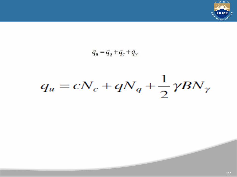
• The ultimate load foundation (that
is,
per unit area of the
the ultimate bearing
116

117

118
FACTORS AFFECTING BEARING CAPACITY

FACTORS AFFECTING BEARING CAPACITY
119
FACTORS AFFECTING BEARING CAPACITY

120
EFFECT OF SHAPE

121
EFFECT OF WATER TABLE
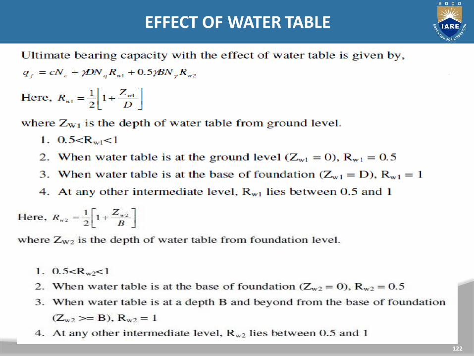
122
EFFECT OF WATER TABLE

123
EFFECT OF WATER TABLE
124

125

126

127

ALLOWABLE BEARING CAPACITY
128
The allowable bearing capacity shall be taken as either of the
following, whichever is less:
• Net ultimate bearing capacity divided by suitable factor of
safety, that is, net safe bearing capacity
• The net soil pressure that can be imposed on the base
without the settlement exceeding the permissible values as
given in IS:1904-1978 to be determined for each structure
and type of soil, that is, safe bearing pressure
SETTLEMENT
129
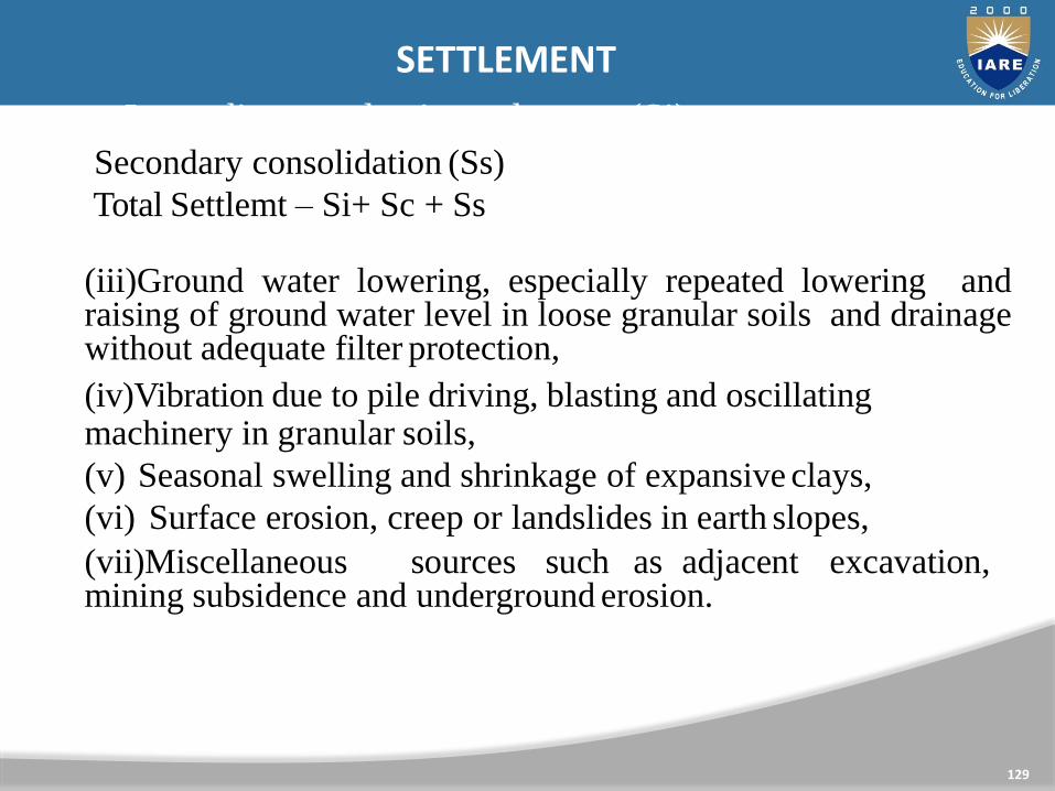
• Immediate or elastic settlement (Si)Secondary consolidation (Ss)
Total Settlemt – Si+ Sc + Ss
(iii)Ground water lowering, especially repeated lowering andraising of ground water level in loose granular soils and drainagewithout adequate filter protection,
(iv)Vibration due to pile driving, blasting and oscillating machinery in granular soils,
(v) Seasonal swelling and shrinkage of expansive clays,
(vi) Surface erosion, creep or landslides in earth slopes,
(vii)Miscellaneous sources such as adjacent excavation, mining subsidence and underground erosion.

METHODS TO COMPUTE SETTLEMENT
130
Elastic settlement
• Theory of elasticity
• Jambu et al
• Schmertmann‘s method
• Pressure meter method
Consolidation settlement
• e- log p curve from oedometer test
• Skempton –Bjerrum method

CONSTRUCTION PRACTICES TOAVOID
DIFFERENTIAL SETTLEMENT
131
Design of the structure and foundation ... desired degree offlexibility of the various component parts of a large structure maybe introduced in the construction.
(i)Choice of a suitable type of foundation for the structure and thefoundation soil conditions...e.g., large, heavily loaded structures onrelatively weak and non-uniform soils may be founded on ‗mat‘ or‗raft‘ foundations. Sometimes, piles and pile foundations may beused to bypass weak strata.
(ii)Treatment of the foundation soil...to encourage the occurrenceof settlement even before the construction of the structure, e.g.,(a) Dewatering and drainage, (b) Sand drains and (c) Preloading.
(iii)Provision of plinth beams and lintel beams at plinth level andlintel level in the case of residential buildings to be founded onweak and compressible strata.

ALLOWABLE ETTLEMENT
132
• The differential settlement should not exceed 75% of the maximum settlement
• Maximum settlement range from 20 mm to 300 mm
• ρ> 150 mm damages the utilities
• IS 1904 (1966)- Permissible settlement
• Isolated footing
On sand -40mm
On clay -65 mm
• Raft
On sand -40mm to 65mm
On clay – 65 to 100 mm

133

SETTLEMENT CALCULATION
134
Es- modulus ofelasticity
I- influencefactor

135

CONSOLIDATIONSETTLEMENT
136
CONSOLIDATION SETTLEMENT

137

138

139

140

141
•Depth/Width >4
•Low Bearing Capacity of soil .
•Non availability of proper bearing stratum
at shallow depths.
•Heavy loads from the super structure for
which shallow foundation may not be
economical or feasible.

142
• A timber, steel or reinforced concrete post usually vertical,used as a structural element for transferring the loads at therequired depth in the deep foundations is called PILE.
• These are the long slender members either driven or cast-in-situ and may be subjected to vertical or lateral or vertical pluslateral loads.

143
may be used for the following purposes,
1. End Bearing or compressive strength: To transfer the loadthrough a soft soil to a suitable bearing stratum by meansof end bearing of the piles.
2. Scour depth. To transfer the load through Water, for anyhydraulic structure because in this case, we have to keepthe foundation at the scour depth below the bed level. ForRiver Ravi Scour depth is 30 to 35m below the bed. So ifwe go for the shallow foundation, we will have to makean open pit, coffer dam diversion of River etc. and it ishighly uneconomical.
3. Tension or Uplift: For a very tall structure (tower), even ifthe Soil is very good, but here the overturning is theproblem. So either make the base very large (Thick raft) ormake deep foundation.
USES OF PILS

144
4) Vibration Control: if then to absorb the vibrations either makea massive block or the next choice is deep foundation, ButMassive black is very expensive. e.g. At Terbela the shaft ofTurbine is 2m and when it runs there area a lot of vibrations.
5) Compaction Piles: In order to compact the granular soils andto increase their bearing capacity, piles are used (compactionPiles).
6) Anchor Piles: To provide Anchorage against horizontal pullfrom sheet piling walls or other pulling forces.
7) Fender piles: To protect Water front structure against impactfrom ships or other floating objects.
8) Batter piles: To resist large horizontal or inclined forces.9) Rapid Construction: Piles can also be used if the time
schedule has much importance.

TYPES OF PILES
145
1. Mode of construction
2. Material of construction
3. Material of load
4. Function of pile
5. Shape
6. Size

CLASSIFICATION BASED ON CONSTRUCTION
146
Cast in-situ Piles(Bored Piles)• Under sized Bore.(It is feasible because of less noise ,
under sized hole is dug and full size pile is driven,(NABWI MOSQUE PILES).
• By driving the piles, the soil is displaced so type is
a) High volume displaced piles (vol. almost equal to vol. of pile).
b) No volume displaced piles.
c) Low volume displaced piles.

CLASSIFICATION WITH RESPECT TO FUNCTION
147
1) Compression pile (To resist the comp. load)
2) Tension pile or Anchor pile
3) Compaction piles granular soil i.e. very loose sand can becompacted by driving the piles at one place, then are pulledout and driven at the next place, in this way sand isdensified).
4) Fender piles (Used near sea-part to protect the Harbour, justto absorb the impact of floating objects)
5) Batter piles (Provided at an inclination their stability is moreagainst overturning).
6) Sheet piles.
(To reduce seepage or to provide lateral stability).

CLASSIFICATION WITH RESPECT TO SHAPE
148
1. Round Piles
2. Square Piles
3. Octagonal Piles
4. I-Shaped Piles
5. Straight Piles
6. Tapered Piles
7. Bell-Bottom Piles
8. Screw Piles
CLASSIFICATION WITH RESPECT TO SIZE
149
1. Large Dia Pile:
2. Small Dia Pile:
3. Micro Dia Pile:
( > 24‖)
( > 6‖to 24‖)
(= 4‖to 6‖)(These are used for specific projects i,e for Repair ).
1. Root Pile(Rectangular) Used for special
projects i,e for under pressing, Repair). If >
24‖ then These are called as pier.
CLASSIFICATION WITH RESPECT TO SHAPE

PILES GROUPS
150

LOAD CARRYING MECHANISAM OF PILES
The ultimate bearing capacity of a pile is the maximum load which it can carry without failure or excessive settlement of the ground. The bearing capacity of a pile depends primarily on 3 factors as given below, Type of soil through which pile is embedded.
mechanism such as Floating Piles or Friction Piles and End-bearing or Point bearing piles. capacity is significantly comprised of skin friction then the pile is classified as Friction piles. Axial Load transfer with depth in a friction pile. Variation of friction around the Pile with depth.
151

152
PILES CAPACITIES
AXIAL CAPACITY
LATERAL CAPACITY
PULL OUT OR TENSION CAPACITY

`
154

155
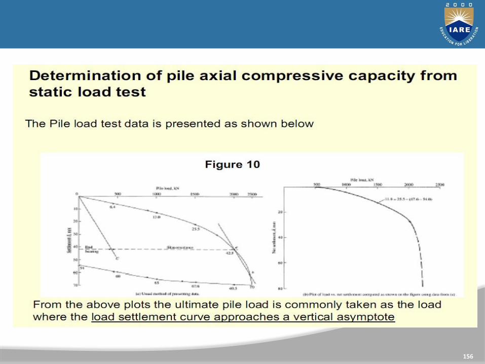
156

UNIT-VWELL FOUNDATIONS
157

CLOs Course Learning Outcome
CLO23 Learn different shapes of well & components of WellFoundation
CLO24 Understand the principle of analysis and design ofwells, Seismic analysis and IRC guidelines
158

WELL FOUNDATION
159
• Well foundation is a box of timber, metal, reinforced concreteor masonry which open both at the top and bottom, and isused for building for building and bridge foundations.
• Well foundations are being used in India from very earlydays. Taj Mahal was built on such foundations.

TYPES OF WELL SHAPES
160
• Circular well
• Rectangular well
• Double Rectangular well
• Double Octagonal well
• Double – D well
• Twin circular well

COMPONENTS OF WELL FOUNDATION
161
• Cutting Edge
• Well Curb
• Bottom Plug
• Steining
• Top Plug
• Well Cap

STEINING
162
• Walls of the wells areknown as steining
• Made of brick masonry,stone masonry, plain orreinforced concrete
• The design of steiningreinforcement rely on skinfriction & unit weight ofwell
• The thickness of steining isdesigned in such a mannerthat all platforms of well aresunk under its own weight

CURB
163
• The curb of a well transfers all the superimposed loads to thesoil through the cutting edge while sinking. The material usedfor curbs may be timber or RCC. The forces acting on wellcurb are shown in Fig. The total horizontal force on the wellcurb on both sides is

SAND FILLING
164
The bottom plug concrete is cured and after curing, the well is
filled with sand in saturated condition. Sand filling provides
1. Stability to the bottom of the well.
2. Eliminate the tensile forces at the base

TOP PLUG
165
The top plug is provided after the filling is completed. Top
plug helps in transferring the load of the pier and
superstructure to the steining. The thickness of the top plug is
generally kept greater than 50 % of the smaller dimension of
the dredge hole. If sand filling is used, the top plug is simply
constructed using PCC of 1:2:4 otherwise it is reinforced with
steel bars and lean concrete of 1:3:6 is used.
WELL CAP
166
• Well cap is constructed as a slab resisting on the well it is used to transfer the load of pier to the well
• As the shape of the well pier and cap are different
• The well cap forms an interim layer to accommodate the pier.
• The well cap is so designed that the base of the pier is provided with a minimum all round offset.
• The centre of the well cap is made to coincide with that of the pier and not with that of the well.
• Such positioning nullifies the effect of the minor shifts which might have occurred during well sinking.

COMPONENTS OF WELL
167

FORCES ACTING ON WELL FOUNDATION
168
Dead loads:it includes weight of superstructure (pier/abutment) + self weightof well.Live loads:Load caused due to tractive effect of vehicles on bridges and road,load due to human beings, furniture floors &other materials Forroad bridges, the live loads may be specified via standardspecifications and code of practice for road bridges.Impact loads:The impact loads is the result of live load and shall beconsidered only during the design of a pier cap and the bridge seaton the abutment. However, for other components of the well thiseffect shall be neglected.Wind loads:The wind loads shall be seen only on theexposed are inelevation and hence acts laterally on the bridge

PROCEDURE FOR SINKING OFWELL
FOUNDATIONS
169
Laying of Curbs
In dry ground excavate up to 15 cm in river bed and place thecutting edge at the required position. If the curb is to be laidunder water and depth of water is greater than 5 m, prepare SandIsland and lay the curb. If depth of water exceeds 5 m built curbin dry ground and float it to the site.

Construction of Well Steining:The steining should be built in short height of 1.5 m initially and 3m after a 6 m grip length is achieved. The verticality should bemaintained. The aim of the well sinking is to sink the wellvertically and at the correct position.
Precautions – The following precautions should be takenduringwell sinking.Outer surface should be regular and smooth. Radius of the curb should be 2 to 4 cm larger than the radius of the steining.Cutting edge should be of uniform thickness and sharpness.Sinking OperationExcavate material under the inside of well curb mechanically or manually Allow the well to remain vertical. Up to a depth of 1 m, excavation underwater can be made manually. When the depth of water exceeds 1 m excavate by Jhams orgrabs.
170

• When well goes on sinking skin friction increases and weight of welldecreased due to buoyancy.
• When the well does not sink, sunk by applying kentledge. If thisoperation is not sufficient jet outside the well or grease the outside. Atypical loading on steining by kentledge is shown inFig.
• Go on adding sections of steining (2 to 5 m in length) up to therequired founding strata.
171

TILT AND SHIFT
172
TILT
The well should be sunk vertical & at the right position through
all kinds of soils IS 3955 – 1967 suggests that tilt should be
restricted to 1 in 60
SHIFT
IS 3955 – 1967 suggests that shift be limited to 1% of depth sunk

RULE OF GRABBING
173