Introduction to Radiographic Interpretation Special Emphasis on CXRs.
51
-
Upload
naomi-childs -
Category
Documents
-
view
224 -
download
1
Transcript of Introduction to Radiographic Interpretation Special Emphasis on CXRs.


Introduction to Radiographic InterpretationSpecial Emphasis on CXRs
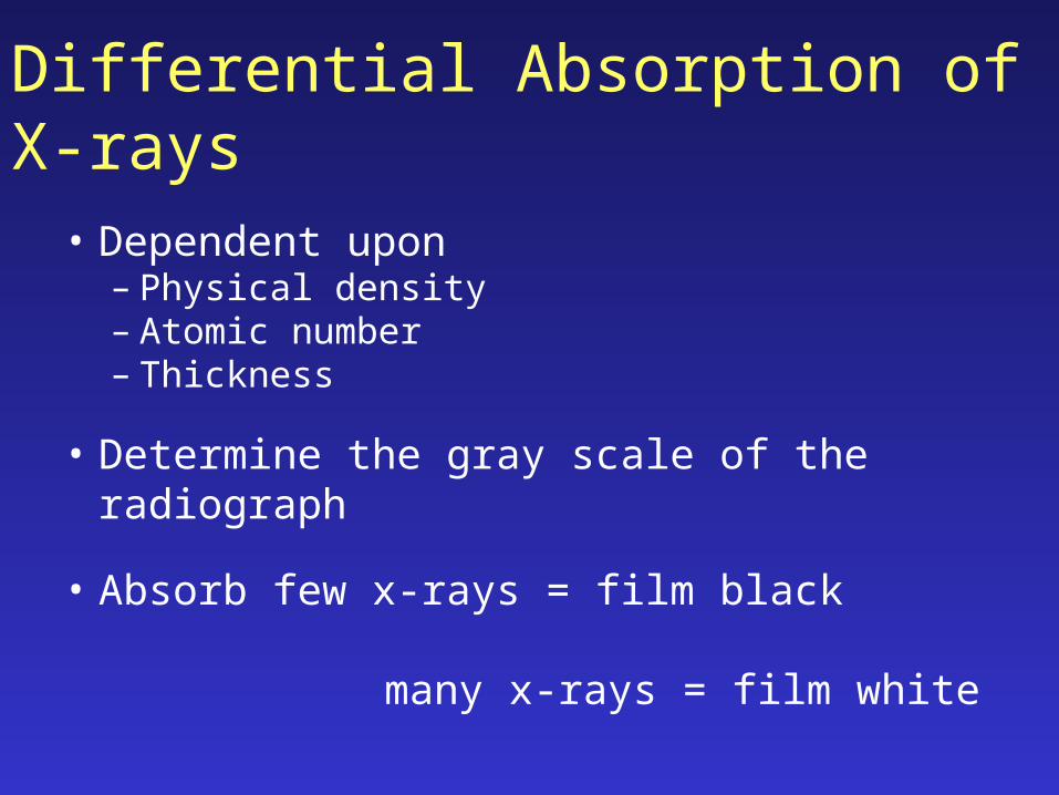
Differential Absorption of X-rays
• Dependent upon– Physical density – Atomic number– Thickness
• Determine the gray scale of the radiograph
• Absorb few x-rays = film black many x-rays = film white
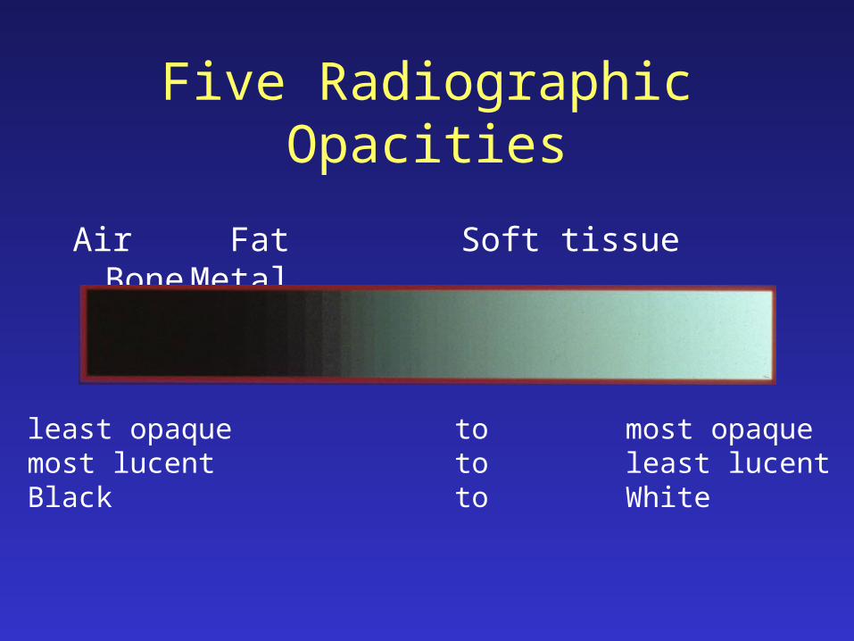
Five Radiographic Opacities
Air Fat Soft tissue BoneMetal
least opaque to most opaquemost lucent to least lucentBlack to White
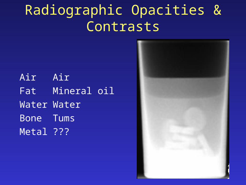
Radiographic Opacities & Contrasts
Air Air
Fat Mineral oil
Water Water
Bone Tums
Metal ???

Five Radiographic Opacities

Five Radiographic Opacities

Standard Radiographic Positions
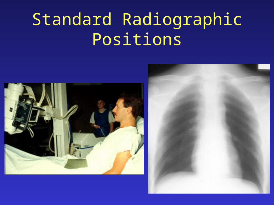
Standard Radiographic Positions

Standard Radiographic Directions
As seen when viewing
DorsalProximalCranial
VentralDistalCaudal
CranialRostralDorsalRight
CaudalPalmarPlantarLeft

Lateral view Cranial-caudal view
Radiograph: two-dimensional image of a three-dimensional object
So . . . What is it?

Dorsoventral view
Radiograph: two-dimensional image of a three-dimensional object
So . . . What is it?

Interpretation Challenges
• Magnification
• Distortion
• Image of a familiar object is unfamiliar
• Loss of depth perception
• Summation
• Silhouette effect

Interpretation Challenges:Magnification
• Enlargement of the radiographic image of an object relative to its actual size
• Increased film-subject distance

Interpretation Challenges:Magnification

Interpretation Challenges:Magnification

Interpretation Challenges:Distortion
• Distortion:Misrepresentation of the true shape of an object

Interpretation Challenges:Unfamiliar image of a familiar object

Interpretation Challenges:Depth perception
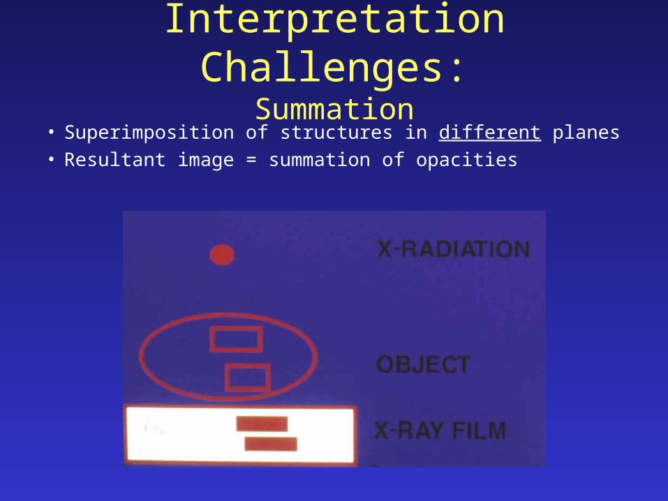
Interpretation Challenges:Summation
• Superimposition of structures in different planes• Resultant image = summation of opacities

Interpretation Challenges:Summation
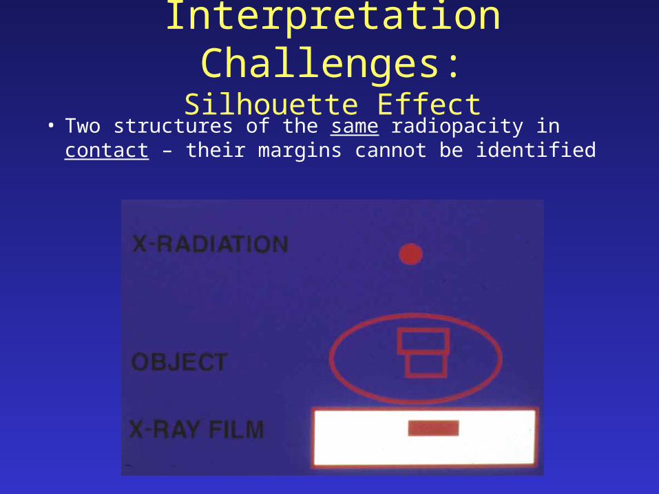
Interpretation Challenges:Silhouette Effect
• Two structures of the same radiopacity in contact – their margins cannot be identified

Interpretation Challenges:Silhouette Effect

Interpretation Challenges:Silhouette Effect

CXR InterpretationHave a system!!
• Method 1:“Outside-to-inside”– Soft tissues– Bony framework– Lungs & hila– Diaphragm & pleura– Mediastinum & heart
• Method 2:“Are There Many Lung
Lesions?”– Abdomen & diaphragm– Thorax– Mediastinum & heart– Lung (single)– Lungs (both)

CXR InterpretationHave a system!!
• Method 1:“Outside-to-inside”– Soft tissues– Bony framework– Lungs & hila– Diaphragm & pleura– Mediastinum & heart
• Method 2:“Are There Many Lung
Lesions?”– Abdomen & diaphragm– Thorax– Mediastinum & heart– Lung (single)– Lungs (both)
A
T
M
L L


CXR InterpretationBeware the poor-quality film!!
• Poor inspiration– High diaphragms,
crowded lung markings
• “Penetration”:– Disappearing thoracic
vertebral details through the heart.
• Rotation:– Note equal distances
from the vertebral spines to the medial ends of the clavicles.

CXR InterpretationBeware the poor-quality film: Inspiration

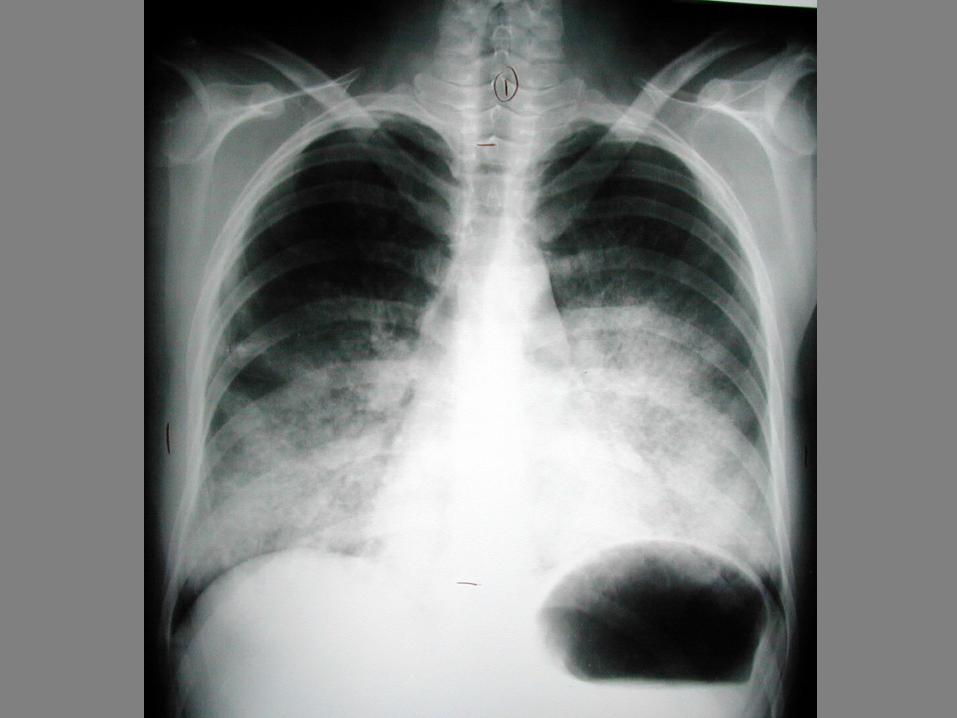
CXR InterpretationNormal structures visible
1. Tracheal air column. 2. Carina. 3. First rib.4. Peripheral lung fields have no markings except: 5. The minor fissure. 6. Top of the R diaphragm is usually between the
anterior 6th & 7th ribs, and overlying the posterior 10th & 11th ribs.
7. Left diaphragm is lower (in 90-95%) by roughly half an interspace.
8. Inferior margins of the posterior ribs.9. Anterior mediastinal line.10. Superior vena cava.11. Azygous vein.12. Right descending pulmonary artery. 13. Pulmonary arteries and veins. 14. Right atrium. 15. Inferior vena cava. 16. Aortic arch. 17. Left pulmonary artery. 18. Border of the left ventricle. 19. Descending aorta. 20. Fat density lines in the intermuscular fascial
layers

CXR InterpretationNormal structures visible
A. Costophrenic angleB. DiaphragmC. HeartD. Aortic archE. TracheaF. HilumG. Main carinaH. Stomach bubbleI. Ascending aorta

CXR InterpretationNormal structures visible
A. Costophrenic angleB. DiaphragmC. HeartD. Aortic archE. TracheaF. HilumG. Main carinaH. Stomach bubbleI. Ascending aorta

CXR InterpretationNormal structures visible
1. Tracheal air column. 2. Carina. 3. First rib.4. Peripheral lung fields have no markings except: 5. The minor fissure. 6. Top of the R diaphragm is usually between the
anterior 6th & 7th ribs, and overlying the posterior 10th & 11th ribs.
7. Left diaphragm is lower (in 90-95%) by roughly half an interspace.
8. Inferior margins of the posterior ribs.9. Anterior mediastinal line.10. Superior vena cava.11. Azygous vein.12. Right descending pulmonary artery. 13. Pulmonary arteries and veins. 14. Right atrium. 15. Inferior vena cava. 16. Aortic arch. 17. Left pulmonary artery. 18. Border of the left ventricle. 19. Descending aorta. 20. Fat density lines in the intermuscular fascial
layers

CXR InterpretationPA vs. AP views

CXR InterpretationPA & Lateral views

CXR InterpretationHyperexpansion = “Air Trapping”

CXR Interpretation“Big Lungs” & “Little Lungs”

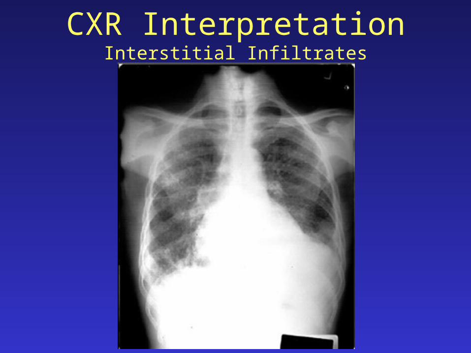
CXR InterpretationInterstitial Infiltrates
A. Generalized interstitial thickening = linear (“reticular”).
B. Discrete interstitial thickening = nodules.
C. Interstitial & alveolar filling = silhouette.
CXR InterpretationInterstitial Infiltrates


CXR InterpretationInterstitial Infiltrates


CXR InterpretationAlveolar Infiltrates
Alveolar-filling, or “airspace” disease:“Pointillist” patterns.Air bronchograms.

CXR InterpretationAlveolar Infiltrates