Differential protection : (protective relaying by Blackburn)

1. Introduction to protective relaying and electromagnetic relays
Shital Patel, EE Department Switch Gear and Protection (2170908) 1
1.1. Electrical fault
Electrical fault is the deviation of voltages and currents from nominal values or states.
Under normal operating conditions, power system equipment or lines carry normal
voltages and currents which results in a safer operation of the system. But when fault
occurs, it causes excessively high currents to flow which causes the damage to
equipments and devices.
Causes of electrical faults are
o Weather conditions
Lightning strikes
Heavy rains/winds/snow
Salt deposition
o Equipment failures
Malfunctioning
Ageing
Insulation failure of cables and winding
o Human errors
Improper rating of equipment or devices
Forgetting metallic parts after servicing or maintenance
Switching the circuit while it is under servicing
o Smoke of fires
Ionization of air, due to smoke particles, surrounding the overhead lines results in
spark between the lines or between conductors to insulator
Electrical faults are classified as
o Short circuit faults: A short circuit fault is an abnormal connection of very low
impedance between two points of different potential. These are the most common and
severe kind of faults, resulting in the flow of abnormal high currents through the
equipment or transmission lines. Short circuit faults are also called as shunt faults.
Symmetrical faults: These are very severe faults and occur infrequently in the
power systems. It affects each of the three phases equally. In transmission line
faults, roughly 5% are symmetric.
Line to line to line to ground (L-L-L-G)
Line to line to line (L-L-L)
Unsymmetrical faults: These are very common and less severe than symmetrical
faults. It does not affect each of the three phases equally. In transmission line
faults, roughly 95% are unsymmetrical.
Line to ground (L-G)
Line to line (L-L)
Line to line to ground (L-L-G)
1. Introduction to protective relaying and electromagnetic relays
Shital Patel, EE Department Switch Gear and Protection (2170908) 2
o Open circuit faults: These faults occur due to the failure of one or more conductors.
Open circuit faults are also called as series faults. These are unsymmetrical or
unbalanced type of faults except three phase open fault.
One conductor open
Two conductor open
o Transient faults: A transient fault is a fault that is no longer present if power is
disconnected for a short time and then restored. Basically, transients are momentary
changes in voltage or current that occur over a short period of time i.e. interval is
usually described as approximately one sixteenth of a voltage cycle.
Effects of electrical faults are
o Heavy short circuit current causes damage to equipment due to overheating and high
mechanical forces set up.
o Arc associated with short circuits causes risks of fire. There is also a possibility of the
fire spreading to other parts of the system if the fault is not isolated quickly.
o At the time of fault supply voltage of the healthy phases gets reduces, that results in
the loss of industrial loads.
o Short circuit causes the unbalancing of supply voltages and currents that increases
the heating of rotating machines.
o Reduction in supply voltage is sometimes so large that, a voltage coil of relay is
damaged.
o Fall of supply voltage and frequency due to fault, loads such as motors starts feeding
the faults i.e. acts as source of power to fault
o Due to fault, individual generators in a power station losses synchronism i.e.
possibility of complete shutdown of the system and in some cases loss of stability of
interconnected systems can also result.
o A very high fault current causes damage to the equipment of a power system that
results in interruption of supply. Hence utility companies loses the revenue due to
long interruption in service, as the repairs of the damaged equipment takes time. On
the other hand, industries are also in trouble because of loss of production.
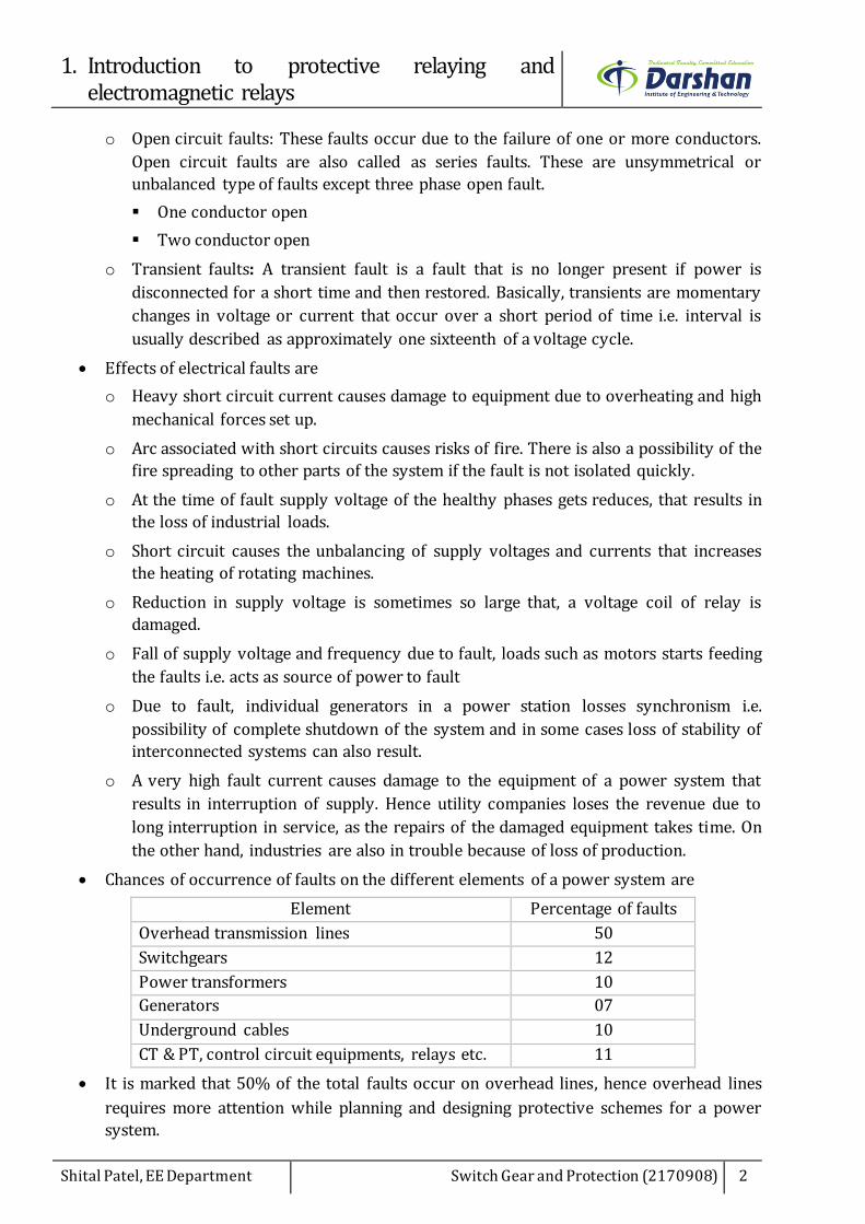
Chances of occurrence of faults on the different elements of a power system are
Element Percentage of faults
Overhead transmission lines 50
Switchgears 12
Power transformers 10
Generators 07
Underground cables 10
CT & PT, control circuit equipments, relays etc. 11
It is marked that 50% of the total faults occur on overhead lines, hence overhead lines
requires more attention while planning and designing protective schemes for a power
system.

1. Introduction to protective relaying and electromagnetic relays
Shital Patel, EE Department Switch Gear and Protection (2170908) 3
1.2. Major components of an electrical power system
CB CB
CB
CB
CB CB CB CB
CB
CB
CBCB CBCB
CB
CB
Transformer11/132 kV
Transformer132/66 kV
Transmission Line132 kV
132 kVSwitchyard
132 kVBus
66 kVBus
66 kVSwitchyard
Transmission Line66 kV
Transformer66/11 kV11 kV
Bus
Feeder11 kV
Transformer11/0.415 kV
Distributor415 V
Consumers
Electrical power is usually generated at voltages 11 kV and then this power is transmitted
at a voltage of 132 kV, 220 kV, 400 kV or higher value depending on line length and
amount of power.
This power is received by a receiving substation where it is stepped down to a voltage of
66 kV or 132 kV depending on distance of further transmission. The 66 kV transmission
line terminates at a distribution substation, where the voltage is stepped down to 11 kV.
11 kV feeders supplies some of HT consumers and pole mounted transformers in
different areas of cities and villages. Pole mounted transformers step down the voltage to
415 volts for use by the consumers.
Different components of the electrical power system are isolated by circuit breakers. In
case of fault, electrical quantities such as current, voltage, phase angle, power, frequency
etc. are sensed by relays with the help of current transformer (CT) and potential
transformer (PT).
The relays are operated as per their characteristics and on their operation, a signal is
transmitted to circuit breakers. On receiving the signal, circuit breaker opens its contacts
and isolates the faulty section from healthy section.
There is an economic limit to the amount that is spent on a protective system. The
protective system to be employed depends upon many factors such as probability of
occurrence of faults, probability of failure of equipment, importance of equipment, cost
of the system or plant, location of plant etc.
Element Cost of relaying (%)
Relays 0.55
Relay panels 0.25
Wiring 0.10
Current transformers 3.10
Potential transformers 1.08
Total 5.08

1. Introduction to protective relaying and electromagnetic relays
Shital Patel, EE Department Switch Gear and Protection (2170908) 4
As a breaker manually makes or breaks the transmission line or electrical equipment, its
cost is not usually considered under protective gear.
1.3. Basic tripping circuit
CB
CT
Relay
Feeder
Bus
PT
Relay
Bus
CB
Feeder
CT
Auxiliary Switch
When any section of power system or equipment needs to be protected, a primary of
current transformer is connected in series with that.
While secondary of current transformer (CT) is connected to current coil of the relay.
If the relay is two quantity relay, secondary of potential transformer (PT) is also
connected to potential coil of the relay.
When fault occurs, a current flowing through that section of power system or equipment
increases to a very high value.
Fault current also flows through the CT primary and accordingly increases the CT
secondary current that further increases relay coil current.
Thus relay contacts get closed under the influence of such high fault current.
Consequently trip circuit of circuit breaker get closed and current starts flowing from
battery through trip coil.
Once trip coil of circuit breaker is energized, it activates the circuit breaker opening
mechanism and open the breaker contacts.
This is how faulty section of power system or equipment gets isolated from healthy one.
Another important device in trip circuit is an auxiliary switch (52-a) which is
mechanically coupled with operating mechanism of circuit breaker.
It is ON when the circuit breaker is ON and OFF when the circuit breaker is OFF.
As auxiliary switch is in trip circuit hence when it opens, it breaks the current in trip
circuit. Once the current in trip circuit interrupts, the relay contacts comes to normal
position.
The purpose of auxiliary switch is that breaking of trip circuit takes place at auxiliary

1. Introduction to protective relaying and electromagnetic relays
Shital Patel, EE Department Switch Gear and Protection (2170908) 5
switch contacts and hence possible arcing due to current interruption across relay
contacts is eliminated.
Also a circuit breaker tripping takes a time ranging from 1 to 5 cycles. A trip coil is not
designed for energizing it continuously once the breaker trips.
It is possible that auxiliary relay contact gets locked due to some internal mechanism
failure, hence a continuous current flows through the trip coil if auxiliary switch (52-a) is
not provided in the trip circuit.
Many other functions such as annunciations, alarms, interlocks, are simultaneously
performed through multi contact auxiliary switch when the relay operates.
Auxiliary switch is generally placed in control cabinet of circuit breaker.
1.4. Zones of protection
CB
Generatorprotection
Transformerprotection
CB
CBCB
CBCB
CB CB
CB
CB
CB
CB
Transmission lineprotection
Switchgearprotection
Switchgearprotection
Switchgearprotection
A power system is combination of various equipments such as generators, transformers,
busbar, transmission lines and distribution lines.
Due to varied nature in operation of equipments or element, power system is divided into
a number of zones of protection, each covering one type of equipment. Specific circuit
breakers and relays are associated with each zone. Zones of protection are always
overlapped so that there is no blind spot i.e. no unprotected portion.
A protective zone covers one or at the most two elements of a power system. Adjacent

1. Introduction to protective relaying and electromagnetic relays
Shital Patel, EE Department Switch Gear and Protection (2170908) 6
protective zones overlaps each other. If no overlapping is considered than fault on the
boundary of the zones does not lie in any of the zones, hence no circuit breaker trips.
These zones are decided by locations of current transformers. For a fault in an overlapped
zone, the relays in both the concerned zones trips and isolates large portion of the power
system unnecessarily. But this is required to avoid the blind spot.
In practice all the zones are not as marked out, the start is defined but the reach depends
upon measurement of the system quantities i.e. subjected to changes in system conditions
and measurement errors.
1.5. Primary and backup protection
Power system is divided into various zones for its protection and there is a unique
protective scheme for each zone.
Two sets of relays, primary and back up, are usually provided for each zone of protection.
When fault occurs in a specific zone, primary relays of that zone are operated to isolate
the faulty element. The primary relay is the first line of defence.
Normally primary relays has a small zone of operation but operate instantaneously.
A second line of defence is always provided as back up protection which clears the faults
if relays or current transformers or potential transformers or circuit breakers of primary
protection fails to operate due to some reasons.
The reliability of protective scheme required is at least 95%, hence accurate design,
installation and maintenance of the relays, circuit breakers, trip mechanisms, AC and DC
wiring are carried out.
Back up relays has a large zone of operation and operate with a particular time delay
just to give the primary relay sufficient time to operate. They are made independent of
factors that causes primary relay to fail.
When a backup relay operates, a larger part of the power system is disconnected from
the power source. As far as possible, a backup relays are placed at different station.
Types of backup relaying are
(a) Relay backup
It is a local backup protection scheme in which an additional (duplicate) set of relays,
current transformers and potential transformers are provided that trips the same circuit
breaker.
Such backup protection scheme is very costly, hence it is recommended only if the
equipment to be protected is very costly and important.
Backup relays of this protection scheme has different principles of operation from those
of the primary protection.
(b) Breaker backup
It is also a local backup protection scheme used for busbar where a number of circuit
breakers are connected to it.
When a protective relay operates but feeder breaker fails to trip, fault becomes busbar
fault. In this condition all other circuit breaker of that busbar needs to trip. Hence a time

1. Introduction to protective relaying and electromagnetic relays
Shital Patel, EE Department Switch Gear and Protection (2170908) 7
delay relay is operated by the main relay connected to all other circuit breaker.
(c) Remote backup
It is the backup protection scheme in which relays located at next (neighboring) station
provides the backup to entire primary protection to relays, current transformers,
potential transformers, circuit breakers and other elements of existing station when fails
to operate.
Remote backup protection is the most desirable as it does not fail due to the reasons
affecting the failure of the primary protection.
It is the cheapest and the simplest backup protection and is a widely used backup
protection of transmission lines.
1.6. Desirable qualities of protective relaying
Any protective system should satisfy the following requirements
(a) Reliability
It is the ability of the protective system to operate under the predetermined conditions
i.e. relay remain inoperative for a long time before a fault occurs, but if fault occurs relay
must operate instantly and correctly i.e. ability of protective system not failing ever. It is
achieved by redundancy i.e. duplicate the relaying system.
To achieve a high degree of reliability, greater attention is given to the design, installation,
maintenance and testing of the various elements of the protective system.
The contact pressure, the contact material of the relay, prevention of contact
contamination etc. are the important aspects for reliability.
Robustness and simplicity of the relaying equipment also contribute to reliability. A
typical value of reliability of a protective scheme is 95%.
(b) Selectivity or Discrimination
It is the ability of the protective system to isolate faulty section exclusively from the rest
of the healthy system.
A well designed and efficient relay system must be selective i.e. able to detect the point at
which the fault occurs and trip the circuit breaker closest to the fault with minimum or
no damage to the system.
Selectivity is absolute if the protection operates for internal faults in any element of the
power system and selectivity is said to be relative if coordinated settings of protective
relays of different zones used. Differential protection is absolutely selective, whereas
current time graded overcurrent protection and distance protection are relatively
selectivity.
Protective relay must be able to discriminate between a fault and loading conditions like
loss of synchronism of generator and power surges or magnetizing current inrush.
It must be also able to discriminate between conditions for which instantaneous tripping
is required or no operation or a time delay operation is required.

1. Introduction to protective relaying and electromagnetic relays
Shital Patel, EE Department Switch Gear and Protection (2170908) 8
(c) Speed
Electrical equipments are short time rated for high fault currents, hence faster operation
of relays and breakers damages less to the equipment.
For modern power system, the stability is very significant aspect, therefore operating
time of the protective system should not exceed the critical clearing time to avoid the loss
of synchronism.
The time setting of the relays is to be decided on the basis of its short time rating of
equipments to be protected. Operating time of a protective relay is usually one cycle or
half-cycle. For distribution systems the operating time is more than one cycle.
(d) Stability
It is the ability of the protective system to remain inoperative under specified conditions
when high values of fault current is flowing through its protective zone due to an external
fault, which does not lie in its zone.
It is a quality that only unit systems possess because they are required to remain
inoperative under all conditions associated with faults outside their own zones.
(e) Sensitivity
It is the minimum value of fault current at which protective system operates. Relay should
operate when the magnitude of the current exceeds the preset value i.e. pick-up current
and sensitive to operate when the operating current just exceeds pick-up value.
Sensitivity is usually expressed in operating quantity referred to the primary of a
transducer.
There is a difference between the sensitivity of a relay and the sensitivity of a protective
system. The sensitivity of a relay is expressed as the apparent power in VA required for
its operation i.e. 1VA relay is more sensitive than a 3 VA relay.
(f) Economy
It is one of the essential quality of protective system. As a rule, the protective system
should not cost more than 5% of total cost. But sometimes it is economically unjustified
to use an ideal scheme of protection.
(g) Simplicity
The protective system should be simple so that it can be easily maintained. Reliability is
closely related to simplicity. The simpler the protective system, the greater is its
reliability.
1.7. Terms of protective relaying
Operating force or torque: It is a force or torque that tends to close the contacts of the
relay.
Restraining force or torque: It is a force or torque that opposes the operating force or
torque.
Actuating quantity: It is an electrical quantity i.e. voltage, current, frequency, power
factor, phase sequence etc. to which relay responds.

1. Introduction to protective relaying and electromagnetic relays
Shital Patel, EE Department Switch Gear and Protection (2170908) 9
Pick-up level: It is the threshold value of the actuating quantity above which the relay
operates.
Dropout or reset level: It is the threshold value of the actuating quantity below which
the relay is de-energized and returns to its normal position.
Relay time: It is the time delay from the instant of occurrence of fault to the instant of
closing of relay contacts.
Operating time: It is the time which delay from the instant at which the actuating
quantity exceeds the relay pick-up value to the instant at which the relay closes its
contacts.
Reset time: It is the time which delay from the moment the actuating quantity falls below
its reset value to the instant when the relay comes back to its normal position.
Breaker time: It is the time delay from the instant at which circuit breaker opens its
contact to the instant of complete extinguishing of arc.
Fault clearing time: It is the total time from the instant of occurrence of fault to the
instant of complete extinguishing of arc i.e. sum of relay time and breaker time.
Setting: It is the value of actuating quantity at which the relay is set to operate.
Plug setting: It is the pick-up value of current adjusted to the required level in relay.
Tappings are provided on relay coil and connections are carried out to a plug bridge. The
tap values are expressed in terms of percentage full load rating of current transformer
that is associated with relay.
Relay pick-up current = %Current setting × Rated secondary current of CT
If CT ratio is 1000/10 A and current setting is 200% then pick-up current is 20 A. So when
relay coil current is more than or equal to pick-up value, relay operates.
Plug setting multiplier (PSM): It is the ratio of fault current in the relay to relay pick-up
current.
CT primary currentCT secondary current Fault currentCT ratioPSM= =Relay current setting Relay current setting Relay current setting CT ratio
Time multiplier setting (TMS): It is the adjustment of travelling distance of an
electromechanical relay that can control relay time of operation. Its dial is calibrated from
0 to 1 in steps of 0.05.
Actual time of operation = TMS × Time in second corresponding to PSM
If TMS is selected as 0.2 and time corresponding PSM of 10 is 4 second (form relay
characteristic curve) then actual time of operation is 0.8 second.
Burden: It is the power consumed by the relay circuitry at the rated current.
Reach: It is the maximum length of transmission line up to which relay can protect.
Over reach: It is the terms used for relay when it operates when a fault point is beyond
its present reach i.e. its protected length.

1. Introduction to protective relaying and electromagnetic relays
Shital Patel, EE Department Switch Gear and Protection (2170908) 10
Under reach: It is the terms used for relay when it fails to operates when a fault point is
within its present reach i.e. its protected length.
Seal-in relay: It is an auxiliary relay which is energized by the contacts of the main relay.
Its contacts are placed in parallel with the contacts of the main relay and is designed to
relieve the contacts of the main relay from its current carrying duty. It remains in the
circuit until the circuit breaker trips. The seal-in contacts are usually heavier than the
contacts of the main relay.
Reinforced relay: It is an auxiliary relay which energized from the contacts of the main
relay. Its contacts are placed in parallel with the contacts of the main relay and it is also
designed to relieve the contacts of the main relay from its current carrying duty.
The difference between reinforced relay and seal-in relay is that seal-in relay is designed
to remain in the circuit till the circuit breaker operates while reinforced relay is designed
to hold a signal from the main relay for a longer period.
1.8. Classification of protective relays
Protective relays are classified depending on the technology used for construction, speed
of operation, development trends, function etc.
(a) Classification of relays based on technology
Depending on the technology used for construction and operation, relays are classified as
Electromechanical relays
o Electromagnetic relay works on the principle of either electromagnetic attraction or
electromagnetic induction.
o Attracted armature type electromagnetic relay operates through an armature which
is attracted to an electromagnet or through a plunger drawn into a solenoid. It is the
simplest type in construction and responds to AC and DC instantaneous over current
or over voltage.
o Induction type electromagnetic relays contains an electromagnet or a permanent
magnet and a moving part. When the actuating quantity exceeds a certain
predetermined value, an operating torque is developed which is applied on the
moving part. This causes the moving part to travel and to finally close a contact to
energize the trip coil of the circuit breaker. It responds to AC instantaneous over
current or over voltage.
Static relays
o Static relays contain electronic circuitry and electronic components i.e. a comparator
which compares two or more currents or voltages and generates output signal. This
signal is applied to slave relay, an electromagnetic relay which finally closes the
contact.
o Static relays has advantages of having low burden on the CT and PT, fast operation,
absence of mechanical inertia and contact trouble, long life and less maintenance.
o Only disadvantages of static relay is high cost and skilled personnel required to carry
out maintenance and repair.
1. Introduction to protective relaying and electromagnetic relays
Shital Patel, EE Department Switch Gear and Protection (2170908) 11
Numerical relays
o Numerical relay collects sequential samples of the AC quantities in digital data form
through the data acquisition system, and process the data numerically using an
algorithm to calculate the fault discriminants and make trip decisions.
o Key component of this relay is numerical devices i.e. microprocessors,
microcontrollers, digital signal processors (DSPs) etc.
o Main benefits of numerical relay are their economy, compactness, flexibility
reliability, self-monitoring and self-checking capability, multiple functions and low
burden on CT/PT.
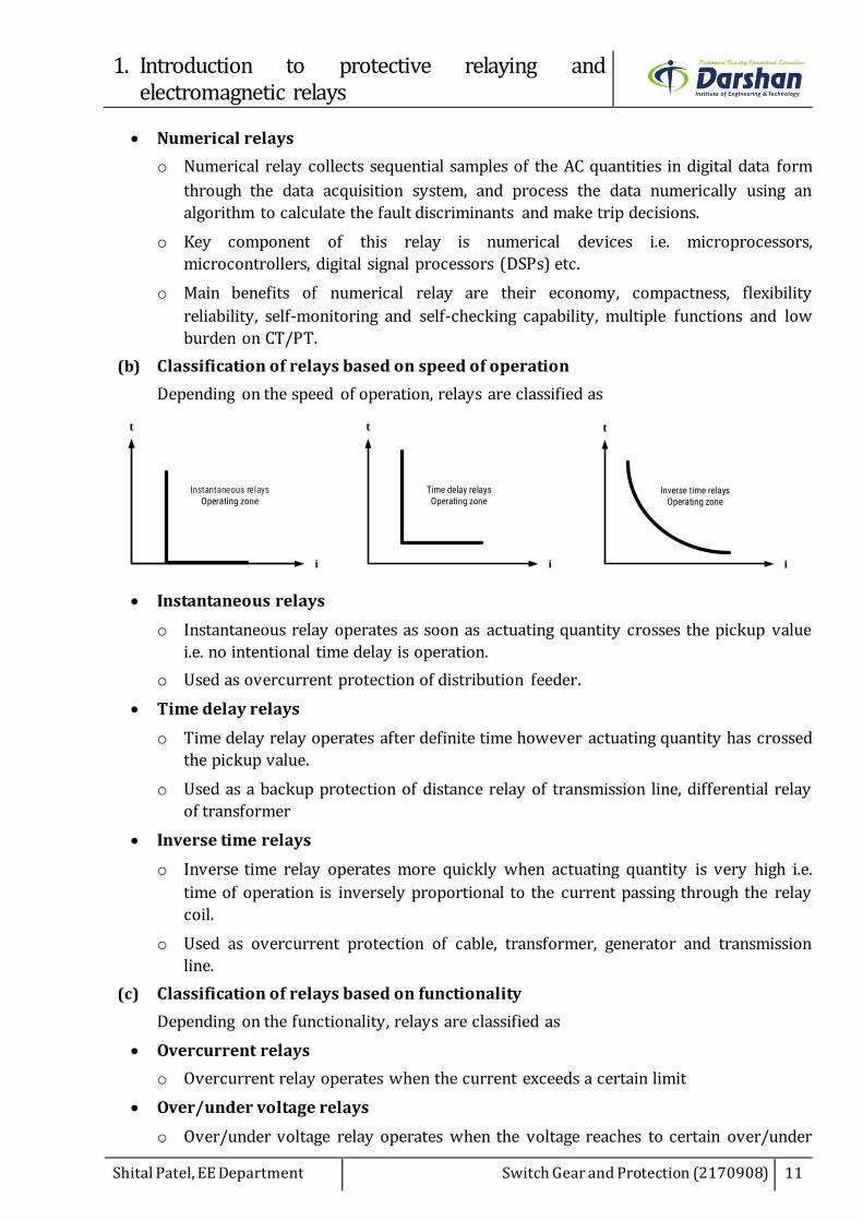
(b) Classification of relays based on speed of operation
Depending on the speed of operation, relays are classified as
t
i
Instantaneous relaysOperating zone
t
i
Time delay relaysOperating zone
t
i
Inverse time relaysOperating zone
Instantaneous relays
o Instantaneous relay operates as soon as actuating quantity crosses the pickup value
i.e. no intentional time delay is operation.
o Used as overcurrent protection of distribution feeder.
Time delay relays
o Time delay relay operates after definite time however actuating quantity has crossed
the pickup value.
o Used as a backup protection of distance relay of transmission line, differential relay
of transformer
Inverse time relays
o Inverse time relay operates more quickly when actuating quantity is very high i.e.
time of operation is inversely proportional to the current passing through the relay
coil.
o Used as overcurrent protection of cable, transformer, generator and transmission
line.
(c) Classification of relays based on functionality
Depending on the functionality, relays are classified as
Overcurrent relays
o Overcurrent relay operates when the current exceeds a certain limit
Over/under voltage relays
o Over/under voltage relay operates when the voltage reaches to certain over/under

1. Introduction to protective relaying and electromagnetic relays
Shital Patel, EE Department Switch Gear and Protection (2170908) 12
voltage preset limit
Over/under frequency relays
o Over/under frequency relay operates when the frequency reaches to certain
over/under frequency preset limit
Impedance relays
o Impedance relay measures the line impedance between the relay location and the
point of fault and operates if the point of fault lies within the protected section.
Directional relays
o Directional relays check whether the point of fault lies in the forward or reverse
direction
(d) Classification of relays based on number of inputs
This type of relays are basically comparators that carries out addition, subtraction,
multiplication or division of some scalar or some phasor quantities and make
comparisons of the input quantities as desired. Depending on the number of input, relays
are classified as
Single input relays
o Single input relay has only one input signal i.e. known as level detectors. It
continuously monitor one electrical quantity and compare it with a reference
quantity.
o An over current relay is an example of single input type that measures the current of
a circuit and compares it with a certain preset value.
o These relays are the simplest in construction and operation, but they fails to attain the
desired reliability as their action depends upon a single quantity only.
Dual input relays
o Dual input relay has two input signals. Such relays measure one quantity and compare
it with another quantity.
o Distance relays and differential relays are the examples of dual input type. The
distance relay measures the current entering the circuit and compares it in magnitude
or in phase angle with the local bus voltage and differential relay measures the current
entering the circuit and compares it with the current leaving the circuit at the other
end.
o Dual input relays are of two type, amplitude comparator type and phase comparator
type. The amplitude comparator compares only the amplitude of the two input signals
irrespective of phase angle between them, whereas the phase comparator compares
only the phase angle between the two input signals irrespective of their magnitudes.
Multi input relays
o Multi input relay has more than two input signals and are used for the realization of
special characteristics other than straight lines or circle.
o Two types of multi input relays are available, amplitude comparator type and phase
comparator type. The amplitude comparator is used for realization of conic

1. Introduction to protective relaying and electromagnetic relays
Shital Patel, EE Department Switch Gear and Protection (2170908) 13
characteristics such as elliptical or hyperbolic, whereas phase comparator is used for
realization of quadrilateral characteristic.
1.9. Classification of electromagnetic relays
Electromagnetic relays are operated by the mechanical force produced by the input
quantity. This force results in movement of the moving part that closes the relay contacts.
Principal types of electromagnetic relays are
o Attracted armature relays
Hinged armature type relay
Plunger type relay
Balanced beam type relay
Moving coil type relay
Polarized moving iron type relay
Reed type relay
o Induction relays
Induction disc relay
Induction cup relay
Attracted armature type electromagnetic relay operates through an armature which is
attracted to an electromagnet or through a plunger drawn into a solenoid. It is the
simplest type in construction and responds to AC and DC instantaneous over current or
over voltage.
Induction type electromagnetic relays contains an electromagnet or a permanent magnet
and a moving part. When the actuating quantity exceeds a certain predetermined value,
an operating torque is developed which is applied on the moving part. This causes the
moving part to travel and to finally close a contact to energize the trip coil of the circuit
breaker. It responds to AC instantaneous over current or over voltage.
1.10. Attracted armature type electromagnetic relays
Attracted armature relay responds to AC and DC quantity. These relays are operate by
the virtue of armature being attracted to the pole of electro magnet or plunger drawn into
a solenoid.
The electromagnetic force exerted on the moving element i.e. armature or plunger is
proportional to the square of the flux in the air gap or the square of the current. It is single
input type of relay that responds to AC and DC quantity both. The motion of the moving
element is controlled by an opposing force generally due to gravity or a spring.
For DC relays, the total electromagnetic force remains constant.
2
DCF KI
For AC relays, the total electromagnetic force pulsates at double frequency.
22 2 2 21 2 1 12
2 2 2m m m m
Cos tF Ki K I Sin t KI KI KI Cos t

1. Introduction to protective relaying and electromagnetic relays
Shital Patel, EE Department Switch Gear and Protection (2170908) 14
o Above equation has two components, first component independent of time and
second components dependent of time.
o Hence restraining force produced by spring is constant and electromagnetic force
developed is pulsating.
o Because of pulsation, armature vibrates at double the power frequency. This leads
relay to produce hum, noise, sparking and undesirable make and break of relay
contacts.
(a) Hinged armature type relay
SpringControl
BackStop
Coil
MovingArmature
MovingContact
To TripCircuit
Input
SpringControl
BackStop
Coil
MovingArmature
MovingContact
To TripCircuit
Input
ShadedRing
In hinged armature type of relay, coil is energized by an operating quantity i.e. system
voltage or current that produces a magnetic flux which in turn produces an
electromagnetic force.
An attractive electromagnetic force is proportional to the square of the flux in the air gap
and its magnitude tends to increase as the armature approaches the pole of the
electromagnet.
This type of a relay is used as main relay for the small rating machines and as auxiliary
relays as indicating flags, slave relays, alarm relays, annunciators, semaphores, etc.
Hinged armature type relay works for AC and DC actuating quantity. For DC relays, the
total electromagnetic force remains constant while for AC relays, the total
electromagnetic force pulsates at double frequency. It leads armature to vibrate at double
the frequency and consequently produces a hum and noise.
This difficulty is overcome by using shaded pole electromagnetic construction. The
restraining force is provided by a spring.
The reset to pick up ratio for attracted armature type relays is 0.5 to 0.9.
The VA burden is low i.e. 0.08 W at pick up for the relay with one contact and 0.2 W for
the relay with four contacts.
This relay is an instantaneous relay that operates at very high speed i.e. less than 5 ms.

1. Introduction to protective relaying and electromagnetic relays
Shital Patel, EE Department Switch Gear and Protection (2170908) 15
(b) Plunger type relay
Input
Coil
FixedContact
MovingContact
To Trip Circuit
SpringControl
Plunger type relay, has a solenoid and an iron plunger that moves in and out of the
solenoid to make and break the contact. The movement of the plunger is controlled by a
spring.
This relay works for AC and DC actuating quantity. For DC relays, the total
electromagnetic force remains constant while for AC relays, the total electromagnetic
force pulsates at double frequency.
Now a day’s plunger type relay construction becomes obsolete as it draws more current.
(c) Balanced beam type relay
MovingContact
To TripCircuit
SpringControl
BalancedBeam
RestrainingCoil
OperatingCoil
Balanced beam type relay consists of a beam carrying two electromagnets at its ends. One
is designed to produce operating torque and second is designed to produce retraining
torque.
The beam is supported at the middle and it remains horizontal under normal conditions.
When the operating torque exceeds the restraining torque, an armature fitted at one end

1. Introduction to protective relaying and electromagnetic relays
Shital Patel, EE Department Switch Gear and Protection (2170908) 16
of the beam is pulled and its contacts are closed.
Now a day’s balanced beam type relay construction becomes obsolete. In old days it was
used as impedance relay and differential relays because of its toughness and fast in
operation i.e. within 1 cycle.
(d) Moving coil type relay
Permanent Magnet
MovingContact
FixedContactTo Trip
Circuit
Input
MovingCoil
N s
Input
MovingCoil
Permanent Magnet
MovingContact
FixedContact
Permanent magnet moving coil relay is called polarized DC moving coil relay because it
responds to only DC actuating quantities. Sometimes it can be used for AC actuating
quantities in conjunction with rectifiers.
Rotary moving coil type and axially moving coil type of relay constructions are used now
a days.
The rotary moving coil type construction has a coil wound on nonmagnetic former which
is placed between poles of permanent magnet. The moving coil assembly carries an arm
that closes the contact.
The operating torque is produced due to the interaction between field of the permanent
magnet and that of the coil and it is proportional to the current carried by the coil.
A phosphor bronze spiral spring is provided for resetting torque. The torque exerted by
the spring is proportional to deflection.
Damping is provided by an aluminum former. A copper former is used for heavier
damping.
An axially moving coil type construction has coils wounded on a cylindrical former which
is suspended horizontally. The coil has only axial movement.
This type of relay has only one air gap hence it is more sensitive than the rotary moving
coil relay.
As contact gap is small, axially moving coil relay is a delicate and it has to be handled
carefully.
Moving coil relay has inverse operating time characteristic i.e. operating time of about 1
to 2 cycle. They are most sensitivity type electromagnetic relays i.e. sensitivity of 0.1 mW.

1. Introduction to protective relaying and electromagnetic relays
Shital Patel, EE Department Switch Gear and Protection (2170908) 17
(e) Polarized moving iron type relay
To TripCircuit
MovingContact
FixedContact
Coil
N S
Polarized moving iron relay uses permanent magnet for polarization i.e. permanent
magnet produces flux in addition to the main flux.
As its current carrying coil is stationary, it is more robust in operation. Usually the
operating time of relay is 2 to 15 ms.
Polarization increases the sensitivity of the relay i.e. 0.03 to 1 mW.
(f) Reed type relay
Coil
To TripCircuit
Input
Glass capsule Reed
Seal
Reed type relay consists of a coil and nickel-iron strips sealed in a closed glass capsule.
The coil surrounds the reed contact.
When the coil is energized, a magnetic field is produced that causes the reeds to come
together and close the contact.
Reed relays are very reliable and maintenance free. A heavy duty reed relays can close
contacts carrying 2 kW at 30 A maximum current or at a maximum of 300 V DC supply.
The voltage withstand capacity for the insulation between the coil and contacts is about
2 kV. The open contacts can withstand 500 V to 1 kV.
The sensitivity of the relay is 1to 3 W and operating time is about 1 to 2 ms.
1.11. Induction type electromagnetic relays
Induction relay responds to AC quantity only.
Induction type electromagnetic relays contains an electromagnet or a permanent magnet

1. Introduction to protective relaying and electromagnetic relays
Shital Patel, EE Department Switch Gear and Protection (2170908) 18
and a moving part. When the actuating quantity exceeds a certain predetermined value,
an operating torque is developed which is applied on the moving part. This causes the
moving part to travel and to finally close a contact to energize the trip coil of the circuit
breaker.
Two alternating magnetic flux are required to turn the moving element in induction type
relay and to produce an operating torque, these two fluxes must have a phase difference
between them.
Let, two alternation flux Φ1 and Φ2 induces an emf in the moving part i.e. disc or cup that
further circulate eddy current i1 and i2 in moving part. The interaction of two eddy current
i1 and i2 produces force which rotates the moving part.
1 1
2 2
m
m
Sin t
Sin t
As induced voltages are proportional to rate of change of flux hence eddy currents are
also proportional to rate of change of flux.
11 1 1
22 2 2
m m
m m
d di Sin t Cos t
dt dt
d di Sin t Cos t
dt dt
Net force acting on moving part is the difference of force produced due to eddy current i1
and i2.
2 1
2 1 1 2
2 1 1 2
1 2
1 2
1 2
1 2
m m m m
m m
m m
m m
m m
F F F
i i
Sin t Cos t Sin t Cos t
Sin t Cos t Cos t Sin t
Sin t t
Sin
F K Sin
Above equation suggest that net force action on moving part at every instant is same.
Hence relay operation is free from vibration.
Direction of rotation of moving element depends upon which flux is leading another flux.
As net force on moving element depends on α i.e. torque is zero when α=0 and torque is
maximum when α=90, always there must exists a phase difference between two fluxes.
A various constructions are used to produce the phase difference between two fluxes.

1. Introduction to protective relaying and electromagnetic relays
Shital Patel, EE Department Switch Gear and Protection (2170908) 19
(a) Induction disc type relay
A shaded pole type and watt-hour meter type induction disc relay constructions are
widely used.
Coil
DiscShadedRing
InputRelay Coil
SecondaryCoil
DiscTo TripCircuit
Lower Magnet
Upper Magnet
In the shaded pole type construction, a C-shaped electromagnet with one half of each pole
is surrounded by a copper band i.e. shading ring is used.
Shaded portion of the pole produces a flux that is displaced in space and time with respect
to the flux produced by the unshaded portion of the pole.
These two alternating fluxes displaced in space and time cut the aluminium disc and
produce eddy currents.
Torque produced by the interaction of each flux with the eddy current produced by the
other flux causes the disc to rotate.
In watt-hour meter type construction, two electromagnets with one at upper side and
second at lower side are used.
Each magnet produces an alternating flux that is displaced in space and time cuts the
aluminium disc.
Phase displacement between two fluxes produced by upper and lower electromagnets
are obtained by either energizing coils of each magnet by two different sources or
resistances and reactances of each coil is designed different.
Permanent magnet is employed to produce eddy current braking to the disc. The braking
torque is proportional to the speed of the disc. When the operating current exceeds pick-
up value, driving torque is produced and the disc accelerates to a speed where the braking
torque balances the driving torque.
A spring is used to supply the resetting torque. At a current below pick-up value, the disc
remains stationary by the tension of the control spring acting against the normal
direction of disc rotation.

1. Introduction to protective relaying and electromagnetic relays
Shital Patel, EE Department Switch Gear and Protection (2170908) 20
The disc rests against a backstop. The position of the backstop is adjustable i.e. distance
by which the moving contact of the relay travels before it closes contacts. This distance of
travel is adjusted for the time setting of the relay.
The disc carries an arm which is attached to its spindle. The spindle is supported by
jewelled bearings. The arm bridges the relay contacts.
Induction disc type relay has inverse operating time/current characteristic and are slow
in operation compared to attracted armature type relays.
The reset to pick up ratio for induction disc type relays is 0.95 because its operation does
not involve any change in the air gap.
VA burden of relay depends on its application i.e. usually 2.5 VA.
(b) Induction cup type relay
Coil
Cup
IronCore
In induction cup type construction, a stationary iron core is placed inside the rotating cup
and spindle of cup carries an arm that closes contacts.
Two pairs of coils produce a rotating field which induces current in the rotor and
interaction between the rotating flux and the induced current produces the torque.
A spring is employed to provide a resetting torque. Brake magnets are not used in this
type of relays.
The inertia of the cup is much less than that of a disc.
The magnetic system is more efficient due to minimum magnetic leakage and low
resistance of the induced current path in the rotor.
Due to the low weight of the rotor and efficient magnetic system its torque per VA is about
three times that of an induction disc type construction i.e. VA burden is greatly reduced.
High torque/inertia ratio makes this relay quite suitable for higher speeds of operation
i.e. operating time of 0.01 second.