INTRODUCTION TO POST-FRAME BUILDING...
16
INTRODUCTION TO POST-FRAME BUILDING SYSTEMS PREPARED BY HARVEY B MANBECK PE PHD HARVEY B. MANBECK, P .E., PHD TECHNICAL ADVISOR NATIONAL FRAME BUILDING ASSOCIATION (NFBA) PROFESSOR EMERITUS PENN STATE UNIVERSITY COPYRIGHT @ 2011 BY THE NATIONAL FRAME BUILDING ASSOCIATION THE NATIONAL FRAME BUILDING ASSOCIATION • Identify the versatility and range of applications for post-frame (PF) building systems • Identify the structural features that make PF building systems unique Id tif th il bl f d i f LEARNING OBJECTIVES • Identify the available resources for design of PF building systems • Identify the primary design approaches for PF building systems • Identify key performance characteristics of PF building systems WHAT DOES A PF BUILDING LOOK LIKE? WHAT IS PF BUILDING USED FOR? • restaurant and retail • churches • commercial PF CONSTRUCTION APPLICATIONS • community • municipal • residential • agricultural 6
Transcript of INTRODUCTION TO POST-FRAME BUILDING...

INTRODUCTION TO POST-FRAME
BUILDING SYSTEMSPREPARED BY
HARVEY B MANBECK P E PHDHARVEY B. MANBECK, P.E., PHD
TECHNICAL ADVISORNATIONAL FRAME BUILDING ASSOCIATION (NFBA)
PROFESSOR EMERITUS PENN STATE UNIVERSITY
COPYRIGHT @ 2011 BYTHE NATIONAL FRAME BUILDING ASSOCIATIONTHE NATIONAL FRAME BUILDING ASSOCIATION
• Identify the versatility and range of applications for post-frame (PF) building systems
• Identify the structural features that make PF building systems uniqueId tif th il bl f d i f
LEARNING OBJECTIVES
• Identify the available resources for design of PF building systems
• Identify the primary design approaches for PF building systems
• Identify key performance characteristics of PF building systems
WHAT DOES A PFBUILDING LOOK LIKE?
WHAT IS PF BUILDING USED FOR?
• restaurant and retail• churches• commercial
PF CONSTRUCTION APPLICATIONS
• community• municipal• residential• agricultural
6
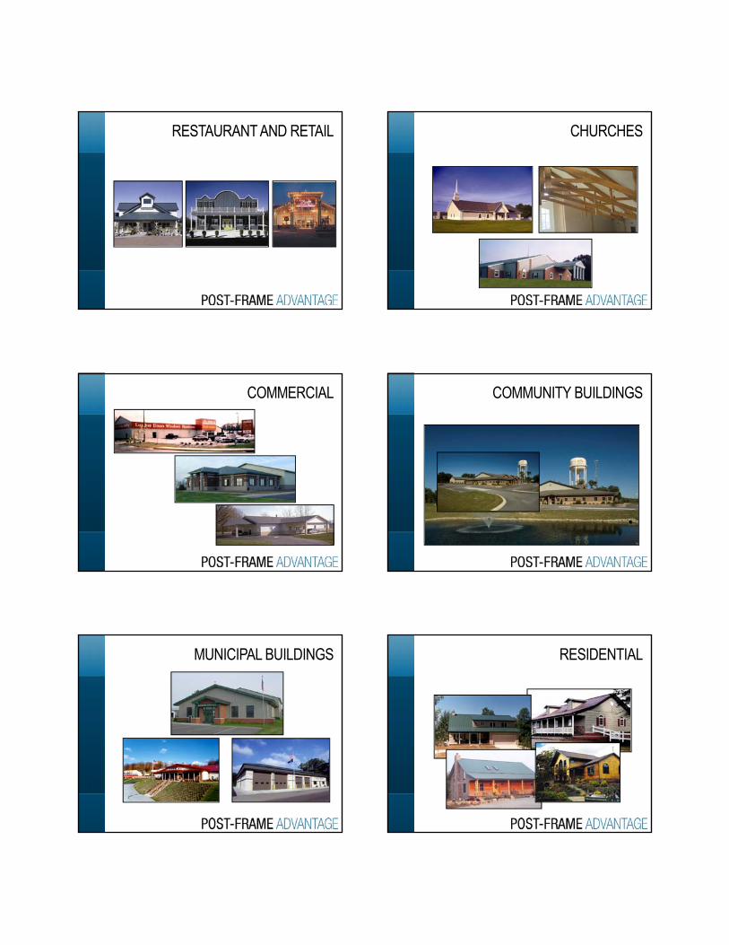
RESTAURANT AND RETAIL CHURCHES
COMMERCIAL COMMUNITY BUILDINGS
MUNICIPAL BUILDINGS RESIDENTIAL
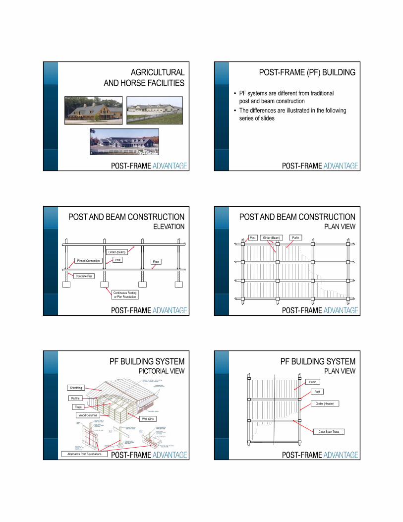
AGRICULTURAL AND HORSE FACILITIES
• PF systems are different from traditional post and beam construction
• The differences are illustrated in the following i f lid
POST-FRAME (PF) BUILDING
series of slides
PostPinned Connection
Girder (Beam)
Fl
POST AND BEAM CONSTRUCTION ELEVATION
Continuous Footingor Pier Foundation
PostPinned Connection
Concrete Pier
Floor
POST AND BEAM CONSTRUCTION PLAN VIEW
Post Girder (Beam) Purlin
PF BUILDING SYSTEM PICTORIAL VIEW
Purlins
Sheathing
Alternative Post Foundations
Wood ColumnsWall Girts
Truss
PF BUILDING SYSTEMPLAN VIEW
Purlin
Post
Girder (Header)( )
Clear Span Truss
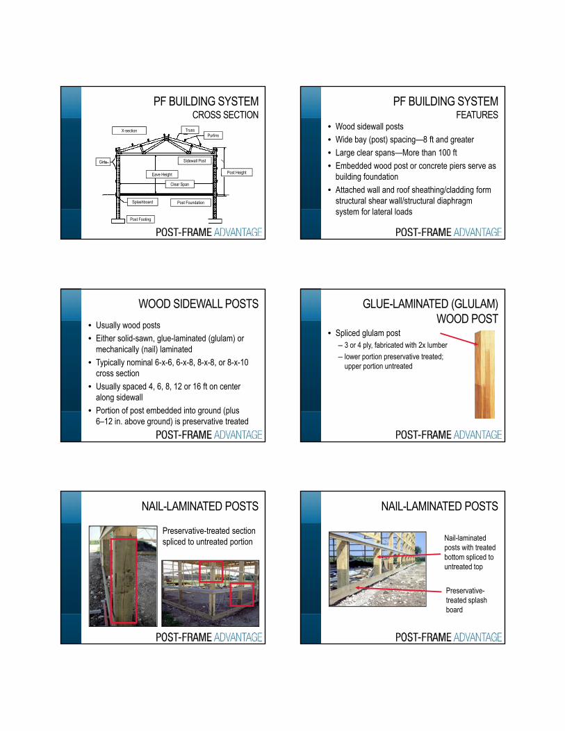
PF BUILDING SYSTEMCROSS SECTION
X-sectionPurlins
Truss
Girts Sidewall PostGirts
Splashboard
Eave Height
Clear Span
Post Height
Post Foundation
Post Footing
• Wood sidewall posts• Wide bay (post) spacing—8 ft and greater• Large clear spans—More than 100 ft
E b dd d d t t i
PF BUILDING SYSTEM FEATURES
• Embedded wood post or concrete piers serve as building foundation
• Attached wall and roof sheathing/cladding form structural shear wall/structural diaphragm system for lateral loads
• Usually wood posts• Either solid-sawn, glue-laminated (glulam) or
mechanically (nail) laminated• Typically nominal 6-x-6, 6-x-8, 8-x-8, or 8-x-10
WOOD SIDEWALL POSTS
Typically nominal 6 x 6, 6 x 8, 8 x 8, or 8 x 10 cross section
• Usually spaced 4, 6, 8, 12 or 16 ft on center along sidewall
• Portion of post embedded into ground (plus 6–12 in. above ground) is preservative treated
• Spliced glulam post– 3 or 4 ply, fabricated with 2x lumber– lower portion preservative treated;
upper portion untreated
GLUE-LAMINATED (GLULAM)WOOD POST
upper portion untreated
NAIL-LAMINATED POSTS
Preservative-treated section spliced to untreated portion
NAIL-LAMINATED POSTS
Nail-laminated posts with treated bottom spliced to untreated topuntreated top
Preservative-treated splash board
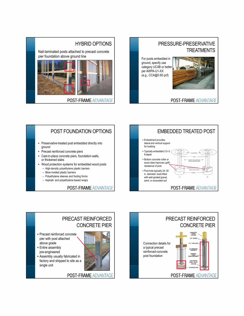
HYBRID OPTIONSNail-laminated posts attached to precast concrete pier foundation above ground line
PRESSURE-PRESERVATIVE TREATMENTS
For posts embedded in ground, specify use category UC4B or better per AWPA U1 XX per AWPA-U1-XX (e.g., [email protected] pcf)
• Preservative-treated post embedded directly into ground
• Precast reinforced concrete piers• Cast-in-place concrete piers, foundation walls,
POST FOUNDATION OPTIONS
or thickened slabs • Wood protection systems for embedded wood posts
– High-density polyethylene plastic barriers– Blow-molded plastic barriers– Polyethylene sleeves and footing forms– Asphalt- and polyethylene-based wraps
EMBEDDED TREATED POST• Embedment provides
lateral and vertical support for building
• Typically embedded 3.5–5 ft-depth
• Bottom concrete collar or wood cleat improves uplift resistance of post
• Post hole typically 24–30 in. diameter; back-filled with well-graded gravel, sand, or excavated soil
PRECAST REINFORCED CONCRETE PIER
• Precast reinforced concrete pier with post attached above grade
• Entire assembly pre-engineered
• Assembly usually fabricated in factory and shipped to site as a single unit
PRECAST REINFORCED CONCRETE PIER
Connection details for a typical precast reinforced-concrete post foundation
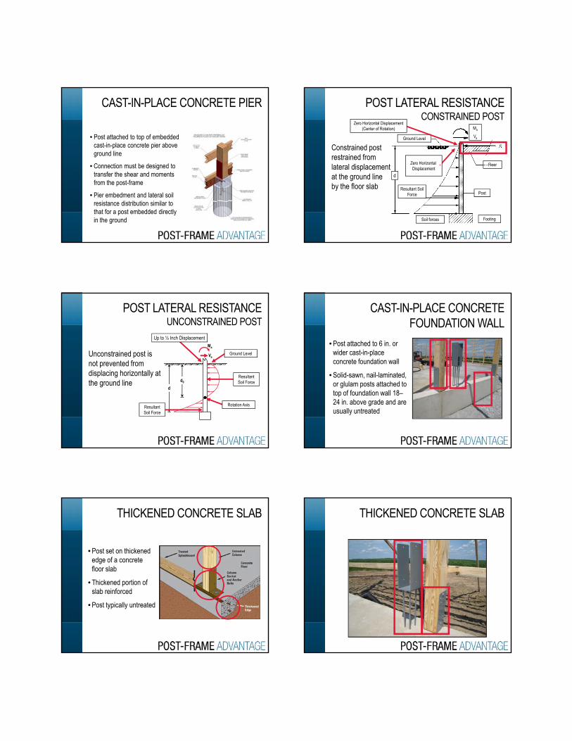
CAST-IN-PLACE CONCRETE PIER
• Post attached to top of embedded cast-in-place concrete pier above ground line
• Connection must be designed to • Connection must be designed to transfer the shear and moments from the post-frame
• Pier embedment and lateral soil resistance distribution similar to that for a post embedded directly in the ground
POST LATERAL RESISTANCE CONSTRAINED POST
Constrained post restrained from l t l di l t
Ground Level
Floor
Ma
Va
Zero Horizontal
Zero Horizontal Displacement (Center of Rotation)
lateral displacement at the ground line by the floor slab Resultant Soil
Force
Floor
Post
FootingSoil forces
dDisplacement
POST LATERAL RESISTANCEUNCONSTRAINED POST
Unconstrained post is not prevented from di l i h i t ll t
Va
Ma
Ground Level
Up to ½ Inch Displacement
displacing horizontally at the ground line
dd0
Resultant Soil Force
Resultant Soil Force
Rotation Axis
CAST-IN-PLACE CONCRETE FOUNDATION WALL
• Post attached to 6 in. or wider cast-in-place concrete foundation wall
• Solid-sawn, nail-laminated, or glulam posts attached to top of foundation wall 18–24 in. above grade and are usually untreated
THICKENED CONCRETE SLAB
• Post set on thickened edge of a concrete floor slab
• Thickened portion of slab reinforced
• Post typically untreated
THICKENED CONCRETE SLAB
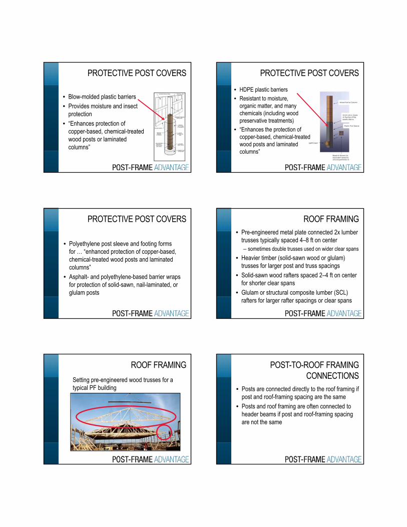
PROTECTIVE POST COVERS
• Blow-molded plastic barriers • Provides moisture and insect
protectionp• “Enhances protection of
copper-based, chemical-treated wood posts or laminated columns”
PROTECTIVE POST COVERS• HDPE plastic barriers• Resistant to moisture,
organic matter, and many chemicals (including wood preservative treatments)
• “Enhances the protection of copper-based, chemical-treated wood posts and laminated columns”
• Polyethylene post sleeve and footing forms for … “enhanced protection of copper-based, chemical-treated wood posts and laminated
PROTECTIVE POST COVERS
columns”• Asphalt- and polyethylene-based barrier wraps
for protection of solid-sawn, nail-laminated, or glulam posts
• Pre-engineered metal plate connected 2x lumber trusses typically spaced 4–8 ft on center– sometimes double trusses used on wider clear spans
• Heavier timber (solid-sawn wood or glulam) t f l t d t i
ROOF FRAMING
trusses for larger post and truss spacings• Solid-sawn wood rafters spaced 2–4 ft on center
for shorter clear spans • Glulam or structural composite lumber (SCL)
rafters for larger rafter spacings or clear spans
ROOF FRAMINGSetting pre-engineered wood trusses for a typical PF building • Posts are connected directly to the roof framing if
post and roof-framing spacing are the same• Posts and roof framing are often connected to
POST-TO-ROOF FRAMING CONNECTIONS
gheader beams if post and roof-framing spacing are not the same
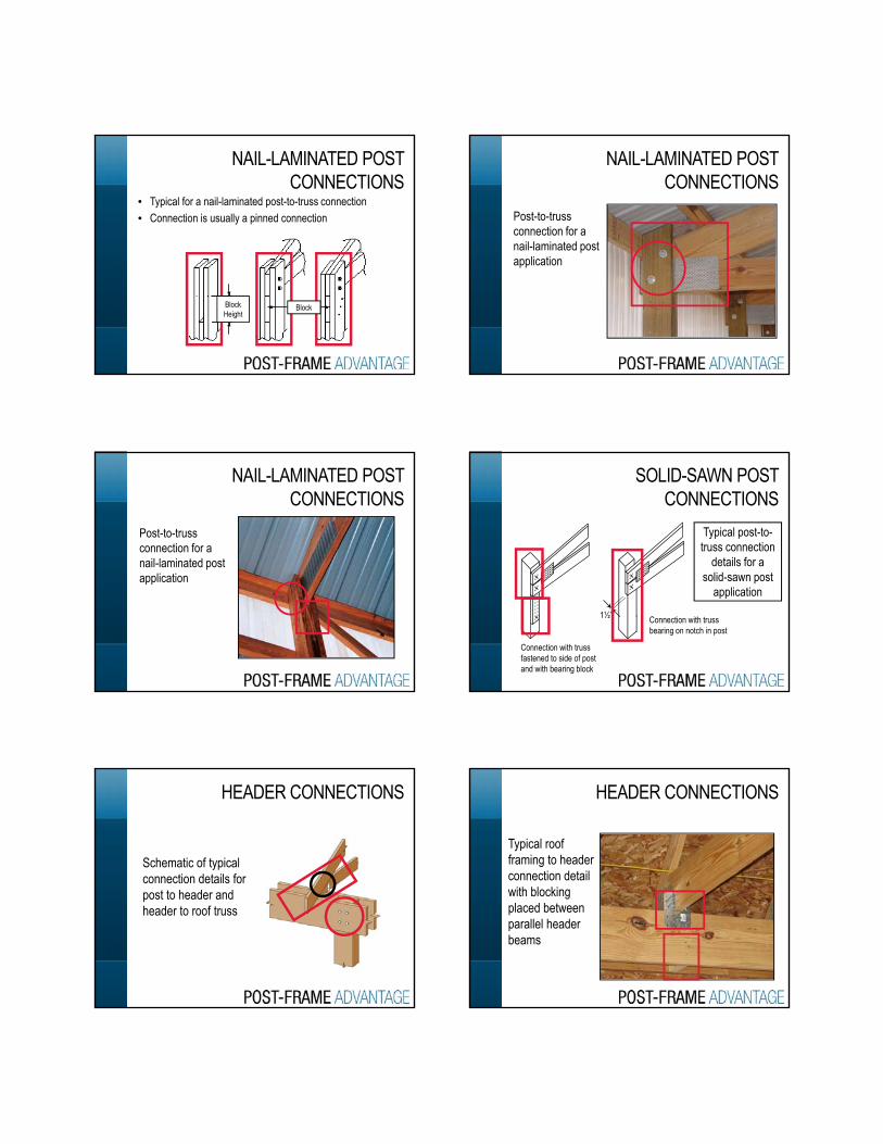
• Typical for a nail-laminated post-to-truss connection• Connection is usually a pinned connection
NAIL-LAMINATED POST CONNECTIONS
Block Height
Block
NAIL-LAMINATED POSTCONNECTIONS
Post-to-truss connection for a nail-laminated post application
NAIL-LAMINATED POST CONNECTIONS
Post-to-truss connection for a nail-laminated post application
SOLID-SAWN POST CONNECTIONS
Typical post-to-truss connection
details for a solid-sawn post
application
1½”
Connection with truss fastened to side of post and with bearing block
Connection with truss bearing on notch in post
HEADER CONNECTIONS
Schematic of typical connection details forpost to header andheader to roof truss
HEADER CONNECTIONS
Typical roof framing to header connection detail
ith bl ki with blocking placed between parallel header beams
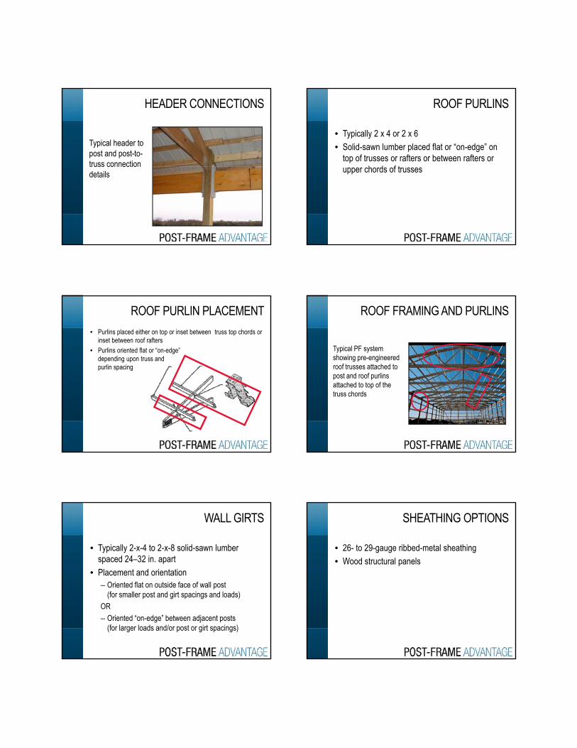
HEADER CONNECTIONS
Typical header to post and post-to-truss connection truss connection details
• Typically 2 x 4 or 2 x 6• Solid-sawn lumber placed flat or “on-edge” on
top of trusses or rafters or between rafters or h d f t
ROOF PURLINS
upper chords of trusses
• Purlins placed either on top or inset between truss top chords or inset between roof rafters
• Purlins oriented flat or “on-edge”depending upon truss andpurlin spacing
ROOF PURLIN PLACEMENT ROOF FRAMING AND PURLINS
Typical PF system showing pre-engineered roof trusses attached to
t d f li post and roof purlins attached to top of the truss chords
• Typically 2-x-4 to 2-x-8 solid-sawn lumber spaced 24–32 in. apart
• Placement and orientation
WALL GIRTS
– Oriented flat on outside face of wall post (for smaller post and girt spacings and loads)
OR– Oriented “on-edge” between adjacent posts
(for larger loads and/or post or girt spacings)
• 26- to 29-gauge ribbed-metal sheathing• Wood structural panels
SHEATHING OPTIONS
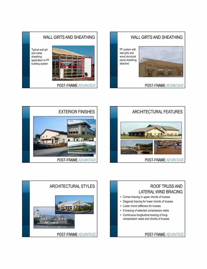
WALL GIRTS AND SHEATHING
Typical wall girt and metal sheathing application to PF application to PF building system
PF system with wall girts and wood structural panel sheathing
WALL GIRTS AND SHEATHING
panel sheathing attached
EXTERIOR FINISHES ARCHITECTURAL FEATURES
ARCHITECTURAL STYLES
• Corner bracing in upper chords of trusses• Diagonal bracing for lower chords of trusses• Lower chord stiffeners for trusses
ROOF TRUSS AND LATERAL WIND BRACING
• X-bracing of selected compression webs• Continuous longitudinal bracing of long-
compression webs and chords of trusses

• Guide to Good Practices for Handling, Installing, Restraining and Bracing of Metal-Plate Connected Wood Trusses (WTCA & TPI)– B1 and B3 summary sheets on handling and
TRUSS BRACING
– B1 and B3, summary sheets on handling and bracing wood trusses, spacing <= 24 in.
– B10, summary sheet on “Post-Frame Truss Installation and Temporary Restraint/Bracing”
• PF buildings are exceptionally easy to insulate to higher levels (R = 20 to 35) required by energy codes with wide range of typical batt, blown-in, or board insulation materials
ENERGY EFFICIENCY
board insulation materials – Large on center post spacing (>4 ft o.c.)– Large wall cavity thickness (6–10 in. typical) are
inherently built into PF without special features
• Thermal bridging effects are minimal in PF– Large spacing (4–10 ft) between wall posts– Thermal resistance of the 6–10 in. wood post at
insulation breaks is significant (R = 7 5 to 12 5)
REDUCED THERMAL BRIDGING
insulation breaks is significant (R = 7.5 to 12.5)
• Wall and roof framingmembers typicallyspaced 4 to 16 ft o.c.
ENERGY EFFICIENCY
• Fewer breaks in thermalinsulation barrier
ENERGY EFFICIENCY
Thicker wall cavities inherently available due to use of nominal 6x to 10x posts in sidewalls
• PF foundations included in Chapter 1800 of IBC 2006 & 2009 (lateral soil resistance and wood preservative treatment requirements)K PF di h d i d th ti
CODE COMPLIANCE
• Key PF diaphragm design and other practices from the American Society of Agricultural and Biological Engineers (ASABE) cited in Sections 2306.1 of IBC 2006 & 2009
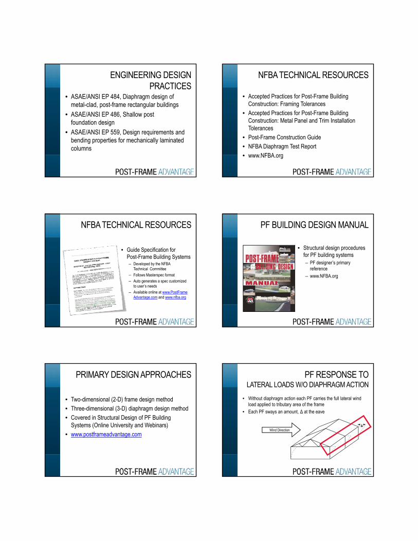
• ASAE/ANSI EP 484, Diaphragm design of metal-clad, post-frame rectangular buildings
• ASAE/ANSI EP 486, Shallow post f d ti d i
ENGINEERING DESIGN PRACTICES
foundation design• ASAE/ANSI EP 559, Design requirements and
bending properties for mechanically laminated columns
• Accepted Practices for Post-Frame Building Construction: Framing Tolerances
• Accepted Practices for Post-Frame Building Construction: Metal Panel and Trim Installation
NFBA TECHNICAL RESOURCES
Construction: Metal Panel and Trim Installation Tolerances
• Post-Frame Construction Guide• NFBA Diaphragm Test Report• www.NFBA.org
• Guide Specification forPost-Frame Building Systems– Developed by the NFBA
Technical Committee
NFBA TECHNICAL RESOURCES
ec ca Co ee– Follows Masterspec format– Auto generates a spec customized
to user’s needs– Available online at www.PostFrame
Advantage.com and www.nfba.org
• Structural design proceduresfor PF building systems– PF designer’s primary
reference
PF BUILDING DESIGN MANUAL
reference– www.NFBA.org
• Two-dimensional (2-D) frame design method• Three-dimensional (3-D) diaphragm design method• Covered in Structural Design of PF Building
PRIMARY DESIGN APPROACHES
g gSystems (Online University and Webinars)
• www.postframeadvantage.com
• Without diaphragm action each PF carries the full lateral wind load applied to tributary area of the frame
• Each PF sways an amount, Δ at the eave
PF RESPONSE TO LATERAL LOADS W/O DIAPHRAGM ACTION
ΔWind Direction
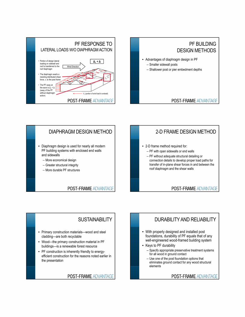
PF RESPONSE TO LATERAL LOADS W/O DIAPHRAGM ACTION
V 2V/2
Δ1 < Δ• Portion of design lateral loading on sidewall and roof is transferred to the roof diaphragm
Wind Direction
∆1
V1 (portion of wind load to endwall)
Vr2Vc2
Vr2Vc2
vv
vv
vv Vr2
vv
v
v
vv
• The diaphragm exerts a resisting distributed shear force, v, to the post frame
• The PF sway at the eave is Δ1 < Δ(sway of the PF without diaphragm action)
• Advantages of diaphragm design in PF– Smaller sidewall posts– Shallower post or pier embedment depths
PF BUILDINGDESIGN METHODS
Shallower post or pier embedment depths
• Diaphragm design is used for nearly all modern PF building systems with enclosed end walls and sidewalls
DIAPHRAGM DESIGN METHOD
– More economical design– Greater structural integrity– More durable PF structures
• 2-D frame method required for:– PF with open sidewalls or end walls– PF without adequate structural detailing or
2-D FRAME DESIGN METHOD
connection details to develop proper load paths for transfer of in-plane shear forces in and between the roof diaphragm and the shear walls
• Primary construction materials—wood and steel cladding—are both recyclable
• Wood—the primary construction material in PF buildings is a renewable forest resource
SUSTAINABILITY
buildings—is a renewable forest resource• PF construction is inherently friendly to energy-
efficient construction for the reasons noted earlier in the presentation
• With properly designed and installed post foundations, durability of PF equals that of any well-engineered wood-framed building system
• Keys to PF durability
DURABILITY AND RELIABILITY
Keys to PF durability– Specify appropriate preservative treatment systems
for all wood in ground contact– Use one of the post foundation options that
eliminates ground contact for any wood structural elements
• PF buildings are durable and reliable if– designed by a qualified design professional– constructed by an experienced PF contractor
t t d i li ith th t i l
DURABILITY AND RELIABILITY
– constructed in compliance with the two previously cited construction tolerance guidelines published by NFBA
• PF is a cost-effective option– Minimal framing material requirements– Minimal footing and foundation material
requirements
OTHER PF BUILDING ATTRIBUTES
requirements– Speed of construction (short time from start of
construction to occupancy)– Construction delays due to cold weather constraints
are minimal
EXAMPLES OF PF BUILDING
COMMERCIAL APPLICATIONS
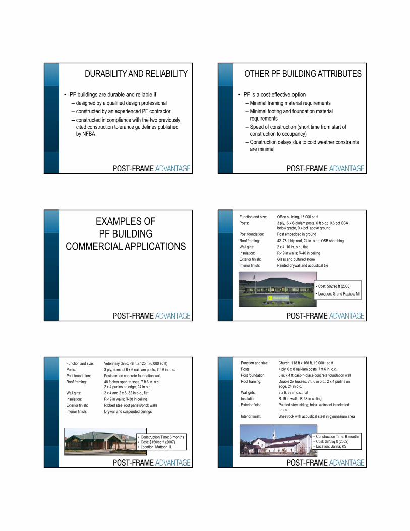
•Function and size: Office building, 16,000 sq ft•Posts: 3 ply, 6 x 6 glulam posts, 6 ft o.c.; 0.6 pcf CCA
below grade, 0.4 pcf above ground•Post foundation: Post embedded in ground•Roof framing: 42–78 ft hip roof, 24 in. o.c.; OSB sheathing•Wall girts: 2 x 4, 16 in. o.c., flat•Insulation: R-19 in walls; R-40 in ceiling•Exterior finish: Glass and cultured stone•Interior finish: Painted drywall and acoustical tile•Interior finish: Painted drywall and acoustical tile
• Cost: $82/sq ft (2003)
• Location: Grand Rapids, MI
•Function and size: Veterinary clinic, 48 ft x 125 ft (6,000 sq ft)•Posts: 3 ply, nominal 6 x 6 nail-lam posts, 7 ft 6 in. o.c.•Post foundation: Posts set on concrete foundation wall•Roof framing: 48 ft clear span trusses, 7 ft 6 in. o.c.;
2 x 4 purlins on edge, 24 in o.c.•Wall girts: 2 x 4 and 2 x 6, 32 in o.c., flat•Insulation: R-19 in walls; R-38 in ceiling•Exterior finish: Ribbed steel roof panels/brick walls•Interior finish: Drywall and suspended ceilingsInterior finish: Drywall and suspended ceilings
• Construction Time: 6 months• Cost: $150/sq ft (2007)• Location: Mattoon, IL
•Function and size: Church, 118 ft x 168 ft, 19,000+ sq ft•Posts: 4 ply, 6 x 8 nail-lam posts, 7 ft 6 in. o.c. •Post foundation: 6 in. x 4 ft cast-in-place concrete foundation wall•Roof framing: Double 2x trusses, 7ft. 6 in o.c.; 2 x 4 purlins on
edge, 24 in o.c.•Wall girts: 2 x 6, 32 in o.c., flat•Insulation: R-19 in walls; R-38 in ceiling•Exterior finish: Painted steel siding; brick wainscot in selected
areas •Interior finish: Sheetrock with acoustical steel in gymnasium area
• Construction Time: 6 months• Cost: $84/sq ft (2002)• Location: Salina, KS
•Function and size: Childcare center, 66 ft x 138 ft, 9,100 sq ft•Posts: 3 ply, 4.5 x 7.5 in. nail-lam, 6 ft o.c.; ACQ
preservative treatment•Post foundation: Posts set on a cast-in-place foundation wall•Roof framing: Single 2x trusses, 6 ft o.c.; heavy timber trusses;
rafters; 2 x 4 purlins on edge, 22 in. o.c.•Wall girts/sheathing: 2 x 4, 24 in. o.c., flat, 0.5 in. OSB•Insulation: R-30 in walls; R-50 in ceiling•Exterior finish: Hardi-Plank
• Construction Time: 4.5 months• Cost: $86/sq ft (2006)• Location: Prescott, WI
•Interior finish: Sheetrock and suspended ceiling
•Function and size: Volunteer Fire Company, 80 ft x 100 ft, 8,000 sq ft•Posts: 3 ply, 4.5 x 7.5 in. nail-lam, 8 ft o.c.; 0.8 pcf CCA
preservative treatment above/below ground•Post foundation: Posts embedded in ground •Roof framing: Single 2x, 80-ft clear span trusses, 8 ft o.c.; 2 x 4
purlins on edge, 24 in o.c.•Wall girts/sheathing: 2 x 4, 30 in o.c., flat•Insulation: R-30 in walls; R-38 in ceiling•Exterior finish: 26-gauge painted ribbed steel•Interior finish: Steel sheathing in bay; sheetrock and suspended
ceilings in office areas
• Construction Time: 6 mos.• Cost: $70 / sq. ft (2007)• Location: Lexington, NC
•Function and size: Educational Center, 64 ft x 112 ft, 7,200 sq ft•Posts: Solid sawn 6 x 6 posts, 8 ft o.c.; CCA at 0.6 pcf •Post foundation: Embedded posts attached to 12 in. Φ concrete footer •Roof framing: Single, 64-ft trusses, 2 ft o.c.; OSB sheathing
attached to truss chords•Wall girts/sheathing: 2 x 4, 24 in o.c., flat; 7/16 OSB •Insulation: R-24 in walls; R-30 in ceiling•Exterior finish: Log siding; ribbed steel roof•Interior finish: Drop ceiling in parts; drywall in parts; some •Interior finish: Drop ceiling in parts; drywall in parts; some
exposed wood
• Construction Time: 6 months• Cost: $72/sq ft (2007)• Location: Medina, OH
•Function and size: Retail sales store, 42 ft x 90 ft + 38 x 60 ft pavilion, 4,800 sq ft
•Posts: 3 ply, 4.5 x 5.5 in. nail-lam, 9 ft o.c.; CCA @ 0.6 pcf above and below ground
•Post Foundation: Posts embedded 4.5-ft below grade and set on cast-in-place concrete footer pad
•Roof framing: 42 ft clear span 2x trusses, 4.5 ft o.c.; 2 x 4 purlins flat wise, 24 in o.c.
•Wall girts/sheathing: 2 x 4, 24 in. o.c., flat; 1 in. cedar plank T&G cedar siding•Insulation: R-19 in walls; R-38 in ceiling•Exterior finish: Architectural shingles on roof; rough cedar plank Exterior finish: Architectural shingles on roof; rough cedar plank
and T&G cedar siding•Interior finish: Drywall; drop ceiling; pine wall liners in deli area;
FRP liner food coolers/baths
• Construction Time: 98 days • Cost: $93/sq ft (2002)• Location: Old Forge, NY
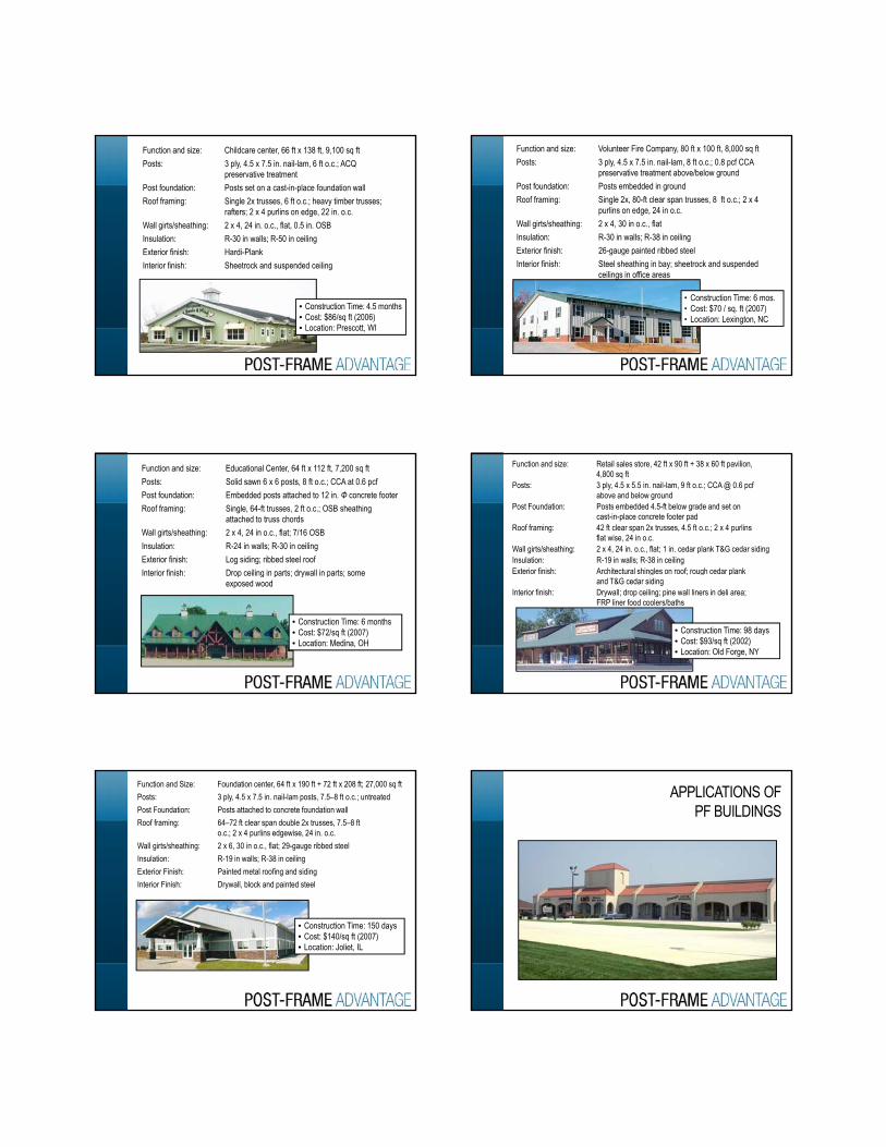
• Function and Size: Foundation center, 64 ft x 190 ft + 72 ft x 208 ft; 27,000 sq ft • Posts: 3 ply, 4.5 x 7.5 in. nail-lam posts, 7.5–8 ft o.c.; untreated• Post Foundation: Posts attached to concrete foundation wall• Roof framing: 64–72 ft clear span double 2x trusses, 7.5–8 ft
o.c.; 2 x 4 purlins edgewise, 24 in. o.c.• Wall girts/sheathing: 2 x 6, 30 in o.c., flat; 29-gauge ribbed steel• Insulation: R-19 in walls; R-38 in ceiling• Exterior Finish: Painted metal roofing and siding• Interior Finish: Drywall, block and painted steel
• Construction Time: 150 days• Cost: $140/sq ft (2007)• Location: Joliet, IL
APPLICATIONS OF PF BUILDINGS
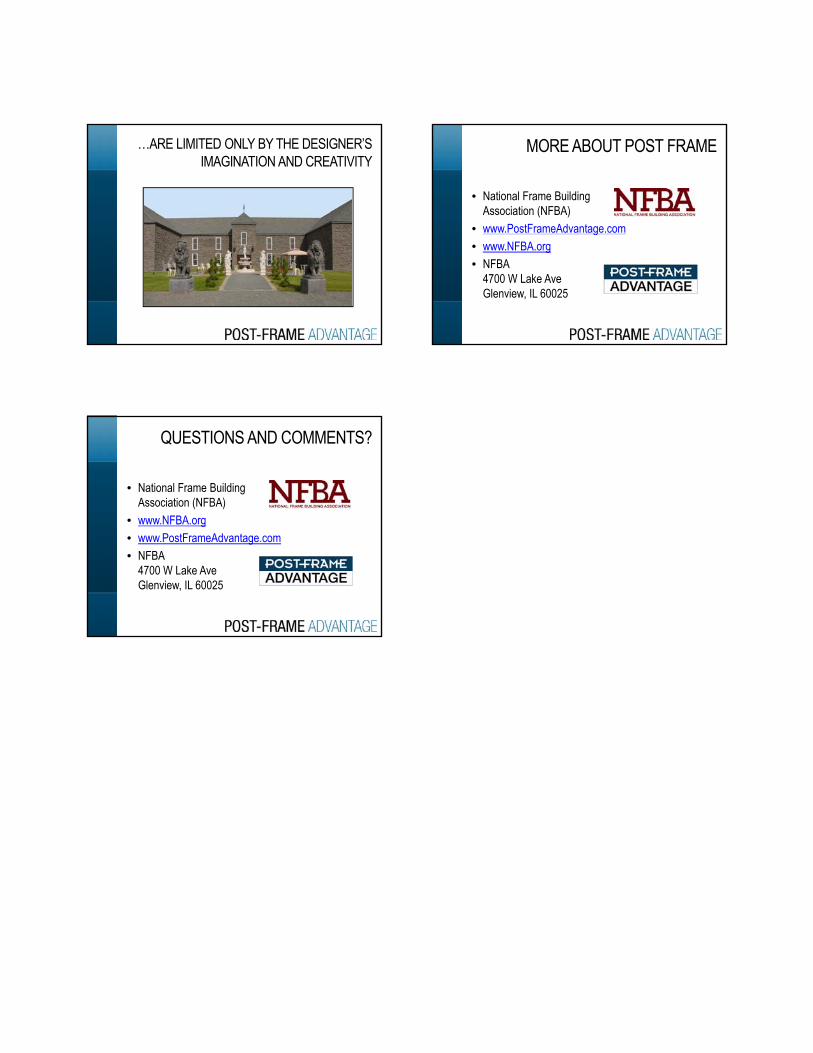
…ARE LIMITED ONLY BY THE DESIGNER’S IMAGINATION AND CREATIVITY
• National Frame Building Association (NFBA)
• www.PostFrameAdvantage.com
MORE ABOUT POST FRAME
g• www.NFBA.org• NFBA
4700 W Lake AveGlenview, IL 60025
• National Frame Building Association (NFBA)
• www.NFBA.org
QUESTIONS AND COMMENTS?
g• www.PostFrameAdvantage.com• NFBA
4700 W Lake AveGlenview, IL 60025