Introduction to Optical Networking - CSE...
91
Introduction to Optical Networking Based on: Rajiv Ramaswami, Kumar N. Sivarajan, “Optical Networks – A Practical Perspective 2 nd Edition,” 2001 October, Morgan Kaufman Publishers
Transcript of Introduction to Optical Networking - CSE...
Introduction to Optical Networking
Based on:Rajiv Ramaswami, Kumar N. Sivarajan, “Optical Networks – A
Practical Perspective 2nd Edition,” 2001 October, Morgan Kaufman Publishers
Gergely Zaruba - CSE6344 Fall 2001
The Information Age! Dramatic changes in the telecomm
industry.! Continuing need for more bandwidth! Tremendous growth of Internet! Exponentially growing WWW information
(average phone call: 3 minutes, average internet session: 20 minutes)
! Internet traffic is doubling every 4 to 6 months!!
Gergely Zaruba - CSE6344 Fall 2001
Growing Bandwidth Need at Home! DSL lines are widely available for
customers with speeds of 1Mbps and higher compared to dial-up lines (2.4-56kbps).! A 10% increase of penetration in US
households (100million) brings in another 1Tbps of traffic assuming that 10% of these people are on simultaneously.

Gergely Zaruba - CSE6344 Fall 2001
Growing Bandwidth Need in the Corporate Sector! Businesses rely on high speed
connections.! Connections are used to interconnect
multiple locations as well as connect businesses to the outside world.
! Businesses that used to lease 1.5Mbps lines are common to lease 155Mbps lines nowadays.
Gergely Zaruba - CSE6344 Fall 2001
Increased Bandwidth Demand vs. Cost of Bandwidth! Strong correlation.! Technological advances -> reduced cost
of bandwidth.! Reduced bandwidth cost ->
development of new set of applications using more bandwidth.
! Increased bandwidth need drives technological advances.

Gergely Zaruba - CSE6344 Fall 2001
Deregulation! Breaking up old phone monopolies.! Monopolies impede rapid progress (no
incentive to reduce costs and provide new services).
! Competition in the market place.! Start-up service providers with new
business plans and companies to provide equipment for them.

Gergely Zaruba - CSE6344 Fall 2001
Change of Traffic! New demand is dominated by data
traffic opposed to voice communication.! But most networks are still optimized
for carrying voice traffic (legacy).! Providers have to change their business
model and the way they build their networks.

Gergely Zaruba - CSE6344 Fall 2001
US Deregulation! -1984: Only one phone company (AT&T) with
local Bell operating companies that it owned. ! In 1984 long distance market was
deregulated and AT&T was broken up (AT&T only long distance; Baby Bells – local services)
! Other long distance providers (MCI, Sprint, etc.).
! Remaining Bells: SWBC, Bell Atlantic, BellSouth and US West (Qwest)
Gergely Zaruba - CSE6344 Fall 2001
Fibre Carrier Classification Today! Size of coverage:
! Metro Carriers! Long-Haul Carriers
! Acces to networks:! Public Networks! Private Networks

Gergely Zaruba - CSE6344 Fall 2001
A Public Network
Long HaulInterexchange Network
~few hundreds orfew thousands km
MetropolitanInteroffice Network
~few tens of km
MetropolitanAccess Network
~few km
Central OfficePoint of Presence (POP)
Business
Home

Gergely Zaruba - CSE6344 Fall 2001
Public Networks! Links are fibre pairs! It is imperative to provide multiple
paths in long-haul networks.! Equipment and fibre can belong to
several different companies.! Undersea networks are important long-
haul networks.
Gergely Zaruba - CSE6344 Fall 2001
Services! Connection oriented services! Connection-less services
OR! Circuit switched (e.g., PSTN)
! Leased or private lines (will we see users “dialing” for high speed private lines?)
! Not efficient for handling bursty data (average and peak rate)

Gergely Zaruba - CSE6344 Fall 2001
Services! Packet switched (e.g., Internet - IP)
! Intended for bursty data transmission! Several packet “streams” are multiplexed
together.! Packet header is added.! Packets are switched (or routed)
individually.! Statistical multiplexing (bandwidth
requirement is reduced)

Gergely Zaruba - CSE6344 Fall 2001
Packet Switched –Statistical Muliplexing! If load is more than the available
bandwidth, queuing/buffering is needed.
! Queuing introduces additional delay and delay jitter.
! Buffer may overflow (packets are dropped)
! Connectionless service – datagram packet service.

Gergely Zaruba - CSE6344 Fall 2001
Packet Switched –Best Effort ! Network tries its best to relay data from
source to destination but offers no guarantees (as opposed to QoS).
! This is today’s Internet but it is slowly evolving.
! This is fine for web browsing and file transfers, but…

Gergely Zaruba - CSE6344 Fall 2001
Packet Switched –Best Effort ! Ethernet is a true best effort
architecture.! FDDI and Frame Relay already included
some QoS support.! ATM had explicite QoS support but
came too late, IP was too strong.! IP is changing (MPLS provides virtual
circuits for better utilization of SMPX, differentiated sercvices, integrated services, IPv6)

Gergely Zaruba - CSE6344 Fall 2001
The Changing Services Landscape
! Line speeds increase from 155Mbps to 2.5Gbps or 10Gbps.
! A carrier’s customer may be another carrier.
! Due to increased competition services have to be delivered rapidly (in minutes or less) for even short contract periods (special events, periodical back-ups).

Gergely Zaruba - CSE6344 Fall 2001
The Changing Services LandscapeAvailability
! Availability – the percentage of time the service is available to the user.
! Typically above 99.999% availability is required today (a downtime of less than 5 minutes a year)
! Very fast restoration service (fibre cuts) ~50ms today
! Full redundancy (half the network is reserved)

Gergely Zaruba - CSE6344 Fall 2001
The Changing Services LandscapeConverging voice and data
! Today voice and date are carried over separate overlay networks.
! Carriers need to maintain multiple networks.
! Carriers would like to migrate to maintaining a single network that enables the delivery of multiple types of services.

Gergely Zaruba - CSE6344 Fall 2001
Optical Networks! Optical networks seem to be the medicine for
all problems in long-haul and metro networking.
! Optical fibre offers way far more BW than copper cables and is less susceptible to electromagnetic interference (also copper is becoming a scarce resource compared to silicon).
! Recently optical fibres became the top choice for short-distance interconnections in large systems.
Gergely Zaruba - CSE6344 Fall 2001
Optical Networks! Optical fibres are widely deployed today
(except perhaps in residential access networks, wiring cost, questionable return (although the for the recent 3G auction high bid in GB all homes could have been equipped with fibre)

Gergely Zaruba - CSE6344 Fall 2001
Optical Networks! Each route in a network comprises many
cables. Each cable contains many fibres.! A 10 mile long route using 3 cables is said to
have 10 route miles and 30 sheath (cable) miles. If each cable has 20 fibres, then the same route is said to have 600 fibre miles.
! By the end of 1998 more than 355,00 sheath miles of fibre (more than 16million fibre miles) in the U.S.

Gergely Zaruba - CSE6344 Fall 2001
(Optical) Transmission Evolving! Higher and higher transmission speeds
over longer and longer distances.

Gergely Zaruba - CSE6344 Fall 2001
First Glimpse at the Generations of Optical Networks
! First generation optical networks:! Optical fibre was used to provide capacity only
(lower BER than copper).! Switching handled electronically! (SONET, SDH, etc.)
! Second generation optical networks:! Some routing, switching intelligence is moving into
the :! Optical Layer

Multiplexing

Gergely Zaruba - CSE6344 Fall 2001
Multiplexing Techniques! It is more economical to transmit at
higher rates on less fibres than vice versa.
! Two fundamental ways to increase capacity of fibre:! Increase the bit rate and multiplex low bit
rate streams via TDM! Wavelength division multiplexing (WDM),
essentially FDM

Gergely Zaruba - CSE6344 Fall 2001
Time Division Multiplexing! 64 155Mbps streams may be multiplexed
into a 10Gbps stream.! Today 10Gbps is reality 40Gbps is soon to
be reality (compared to Tbps of WDM).! Optical Time Division Multiplexing is a hot
area (multiplexing is done optically). In research labs they can reach 250Gbps but it is still years away. Even so it is not sufficient to use only TDM in fibres.
Gergely Zaruba - CSE6344 Fall 2001
Wavelength Division Muxing! Essentially Frequency division multiplexing
but a physicist approach.! Different light-wave light sources (lasers) are
used in the same fibre, thus essentially WDM providing with “virtual fibres”.
! Widely deployed in long-haul (including undersea) networks.
! Recent announcements mention more than 40Tbps using WDM (and TDM).

Gergely Zaruba - CSE6344 Fall 2001
WDM vs TDM

Gergely Zaruba - CSE6344 Fall 2001
WDM and TDM! Complementary techniques, thus can be
combined.! The question is what combination to
use?! E.g., on an intended 80Gbps link should
we use 32 channels of 2.5Gbps or 8 channels of 10Gbps?
! Commercial systems of 1Tbps are becoming available.
Second Generation Optical Networks
Gergely Zaruba - CSE6344 Fall 2001
Problems with First Generation Optical Networks! Optical networks are capable of more
than just point-to-point communication.! Some switching and routing functions
can be added.! Higher data rates => more problems
with electronics (switching speeds) (53 bits, 10Gbps => 42.4ns).
! In first generation networks, all data (even data that has to be relayed) is passed through nodes and electronics.

Gergely Zaruba - CSE6344 Fall 2001
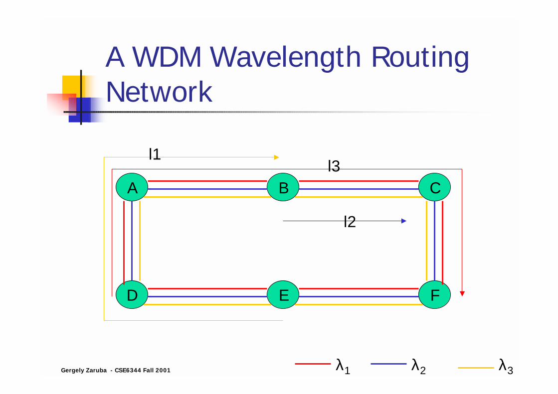
Second Generation Optical Networks! Data that is passed through the node does
not have to be processed by the node:Wavelength routing network.
! Lightpaths: optical connections carried end-to-end from a source to a destination over a wavelength. At intermediate nodes lightpaths (wavelengths) are routed and may be converted to another wavelength (preferably optically).

Gergely Zaruba - CSE6344 Fall 2001
A WDM Wavelength Routing Network
A B C
D E F
λ2 λ3λ1

Gergely Zaruba - CSE6344 Fall 2001
A WDM Wavelength Routing Network
A B C
D E F
λ2 λ3λ1
l1
Lightpath-1

Gergely Zaruba - CSE6344 Fall 2001
A WDM Wavelength Routing Network
A B C
D E F
λ2 λ3
l2
λ1
l1
Gergely Zaruba - CSE6344 Fall 2001
A WDM Wavelength Routing Network
A B C
D E F
λ2 λ3
l2
λ1
l3l1
Gergely Zaruba - CSE6344 Fall 2001
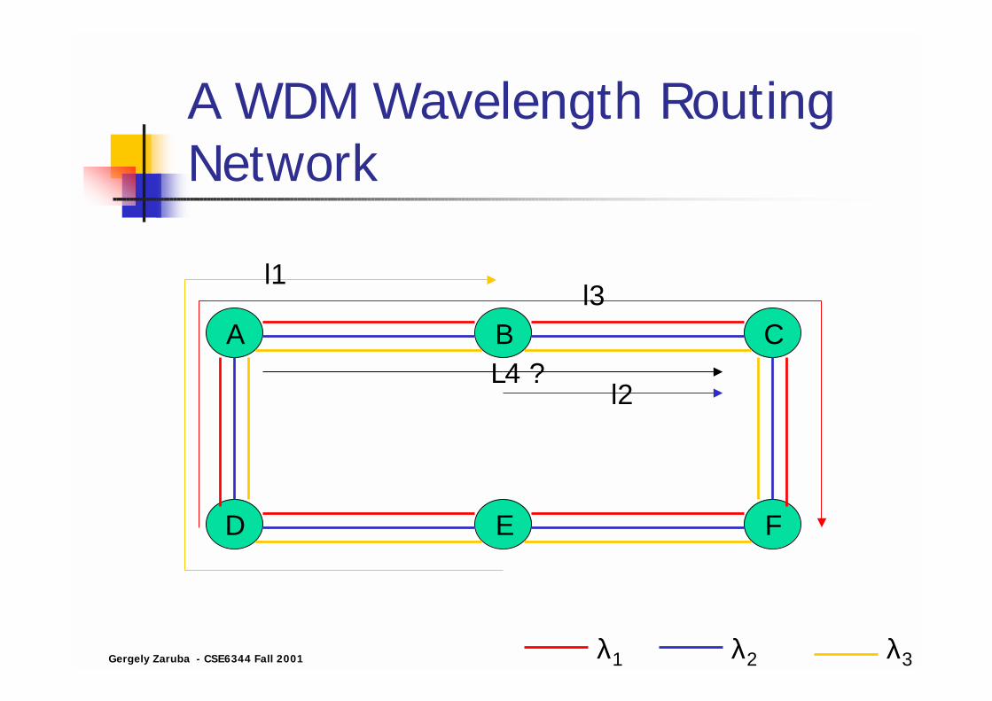
A WDM Wavelength Routing Network
A B C
D E F
λ2 λ3
L4 ?l2
λ1
l3l1

Gergely Zaruba - CSE6344 Fall 2001
A WDM Wavelength Routing Network
A B C
D E F
λ2 λ3
l4l2
λ1
l3l1
Wavelength conversion is needed

Gergely Zaruba - CSE6344 Fall 2001
Wavelength Routing! Spatial reuse of wavelengths: different
lightpaths may use the same wavelength on different links.
! To enhance capabilities wavelength conversion may be considered.

Key Optical Networking Elements

Gergely Zaruba - CSE6344 Fall 2001
Key Networking Elements! Optical Line Terminals (OLTs)! Optical Add/Drop Multiplexers (OADMs)! Optical Crossconnects (OXCs)

Gergely Zaruba - CSE6344 Fall 2001
Optical Line Terminals (OLTs)! Multiplexes multiple wavelengths of
multiple fibres into a single fibre and demultiplexes a set of wavelengths of a single fibre into separate fibres.
! Located at the ends of WDM point-to-point links

Gergely Zaruba - CSE6344 Fall 2001
Optical Add/Drop Multiplexers (OADMs)! Takes signals at multiple wavelengths and
selectively drops some wavelengths while letting others pass through. It can also selectively add a new wavelength (or substitute a wavelength) to the fibre without disturbing other wavelengths.
! Two line ports (in and out) and several local ports for wavelengths to be added/dropped.
! It may include wavelength conversion capabilities.
Gergely Zaruba - CSE6344 Fall 2001
Optical Crossconnects (OXCs)! Essentially similar to an OADM, but
larger scale.! OXCs can have tens or even thousands
of line ports and are able to switch wavelengths from one port to another.
! They may include conversion capabilities.
! There are many different types (to be elaborated later)

The Optical Layer

Gergely Zaruba - CSE6344 Fall 2001
Protocol Stacks! The ISO-OSI 7 layer model is a nice
theoretical approach to network layering and functions.
! Unfortunately today in most networks functions are “smearing the boundaries” between layers.
! Furthermore in a more realistic model would have multiple protocol stack residing on each other.

Gergely Zaruba - CSE6344 Fall 2001
Multiple Protocol Stacks! E.g., IP over SONET
! SONET is used by IP to provide it with point-to-point links

Gergely Zaruba - CSE6344 Fall 2001
Multiple Protocol Stacks! Another (and even more complex)
example is: ! IP over ATM over SONET
! “Yet” another layer is added in second generation optical networks: the optical layer.

Gergely Zaruba - CSE6344 Fall 2001
The Optical Layer! Is a server layer providing services to client
layers:! Provides lightpaths to a variety of higher layers! In future it may provide packet-switched virtual
circuit or datagram services (3rd gen?)

Gergely Zaruba - CSE6344 Fall 2001
Lightpaths in the Optical Layer! Lightpaths could be set-up or torn down
by a request from a higher layer (similar to a circuit switched service like in PSTN).
! Lightpaths may be permanent (and thus fixed at the deployment of the network)
Gergely Zaruba - CSE6344 Fall 2001
SONET vs. Optical Layer! SONET used to be dominant
transmission technology.! The functions of the optical layer are
analogous to those performed by the SONET layer. But it can handle other transmission technologies (more suited for data) as well. Furthermore the most effective processing speed for SONET is at 2.5Gbps, while light waves can easily carry 10Gbps.

Transparency and All-Optical Networks

Gergely Zaruba - CSE6344 Fall 2001
Transparency! The optical layer can be transparent to
the actual data sent over it, meaning that several higher layers can use the optical layer with their own physical specification.
! E.g., a certain maximum and minimum bit rate may be specified and any transmission between that will be routed by the lightpaths.

Gergely Zaruba - CSE6344 Fall 2001
Advantages of Transparency! Several different services can be
provided on the same infrastructure.! The infrastructure if somewhat future-
proof.! New services can be easily deployed
! (An example for an old and very popular transparent service is the one provided by the 4kHz band-limited telephone network (PSTN)
Gergely Zaruba - CSE6344 Fall 2001
All-Optical Network! Data is carried in optical form from
source to destination.! There is no electric-optical or optical-
electric conversion but at the very source and destination nodes.
! Ideally an all-optical network is fully transparent, but in reality it is limited by, e.g., the SNR. (Optical reshaping techniques have not been invented yet.)

Gergely Zaruba - CSE6344 Fall 2001
All-Optical Network! Most networks today are not
transparent, they can only provide for a single bit rate (2.5Gbps or 10Gbps) on wavelengths.
! Optical-electrical conversions may not be avoided. Electronic regeneration is needed depending on the length of the lightpath

Gergely Zaruba - CSE6344 Fall 2001
Electronic Reshaping Techniques! There are 3 types of electronic
reshaping techniques:1. Regeneration with retiming and
reshaping (3R)2. Regeneration with reshaping (2R)3. Simple retransmission, or simple OEO
conversion (1R)

Gergely Zaruba - CSE6344 Fall 2001
Regeneration With Retiming and Reshaping (3R)! Bit clock is extracted from the signal.! The signal is re-clocked.! Results in a fresh copy of the signal.! However it may eliminate transparency
to bit rates and framing protocols.! Large number of regenerations is
possible

Gergely Zaruba - CSE6344 Fall 2001
Regeneration With Reshaping (2R)! No retiming compared to 3R.! Provides transparency to bit rates! Does not provide transparency to
analogue (or multilevel) signals.! Jitter accumulates at every regeneration
step, thus there is a limit on the number of regenerators.
Gergely Zaruba - CSE6344 Fall 2001
Simple Retransmission (1R)! Signal is simply received and
retransmitted.! Can handle analogue data as well.! Performance is significantly poorer than
that of 2R or 3R.
! Optical amplifiers can be thought of as 1R regenerators

Gergely Zaruba - CSE6344 Fall 2001
Transparency of Today’s Networks! Optical Networks are engineered and
built to support several bit-rates and signal types (e.g., SONET, Gigabit Ethernet, etc.).
! Either 2R is employed or there are several 3R devices corresponding to supported bit rates and protocols.

Optical Packet Switching

Gergely Zaruba - CSE6344 Fall 2001
Optical Packet Switching! Research topic.! Packet switching in the optical domain.! Both virtual circuits (portion of full
bandwidth) and datagram services.! Optical Time Domain Multiplexing
(OTDM) can be fixed or statistical.! If it is statistical then it is optical
packet-switched network.

Gergely Zaruba - CSE6344 Fall 2001
All-Optical Packet Switching! Ideally , all functions would be performed in the
optical domain! Optical domain has limited capabilities
=>processing the header and controlling the switch remain in the electronic domain.
! The header could be sent by a lower speed (but ahead of time).
! Lack of optical RAM!! Optical buffers are simple delay lines not RAMs.
! Current packet switches include a high amount of electronics, that is difficult to perform in the optical domain.

Gergely Zaruba - CSE6344 Fall 2001
Optical Packet Switching! Fast optical switching is yet a problem.! A node may impose a new header.

Transmission Basics
Gergely Zaruba - CSE6344 Fall 2001
Wavelengths vs. Frequencies! Wavelength of light pulse (λ): the length (in
nm) of one sinusoid impulse in the transmission medium
! Frequency of pulse (f): How many sinus impulses are transmitted in a second (Hz, THz).
! Speed of light in the transmission medium(c): measured in m/s
c= λf

Gergely Zaruba - CSE6344 Fall 2001
Wavelengths vs. Frequencies! Speed of light in vacuum: 3*108m/s! Approximate speed of light in fibre is
2/3 of that of vacuum: 2*108m/s (thus the wavelengths corresponding to frequencies are also different).
! Typical wavelengths used are around: 800, 1300, and 1500nm (1500nm ~ 133THz)
Gergely Zaruba - CSE6344 Fall 2001
Channel Spacing! Around a center wavelength λ0.
! E.g., at a wavelength of λ0=1500nm, 0.8nm spacing corresponds to 100GHz (typical in WDM).
! Channel spacing is needed to avoid interference between carriers
λλ
∆−=∆ 20
cf

Gergely Zaruba - CSE6344 Fall 2001
Spectral Efficiency! Bandwidth is measured in: Hz, MHz, GHz! Bit rate is measured in: bps, kbps, Mbps! The relationship depend on the modulation
used (e.g., PSTN: 4kHz bandwidth but we can use 56kbps).
! The ratio of bit rate to available bandwidth is called spectral efficiency.
! Optical spectral efficiency is typically around 0.4bps/Hz (i.e., for a 10Gbps bit rate 25GHz of bandwidth is needed)
! Channel spacing needs to be sufficiently larger!

Gergely Zaruba - CSE6344 Fall 2001
Wavelength Standards! 1550 nm band is the most frequently
used band today:! Fibre loss is low! Good components are available
! Wavelengths (and frequencies) have been standardized by ITU (in the frequency domain – constant frequency spacing of 100 or 50GHz)

Gergely Zaruba - CSE6344 Fall 2001
Typical Silica Fibre Characteristic

Gergely Zaruba - CSE6344 Fall 2001
Wavelength Standards! ITU 100GHz spacing standard

Gergely Zaruba - CSE6344 Fall 2001
Wavelength Standards! Today we see systems using 25GHz
spacing, is ITU going to standardize that?! Also C-band (1530-1565nm -conventional)
equipment are available but L-band (1565-1625nm – long) is coming!
! Vendors don’t always agree but this standardization effort helped accelerating the technology.

Optical Fibre Communication –Historical Overview

Gergely Zaruba - CSE6344 Fall 2001
Waveguides! Light signals can be transmitted in
“waveguides” (~1960). (Waveguides enable light signals to be transferred without being scattered.)
! Waveguide consists of:! Core! Cladding
! Using total reflection
Gergely Zaruba - CSE6344 Fall 2001
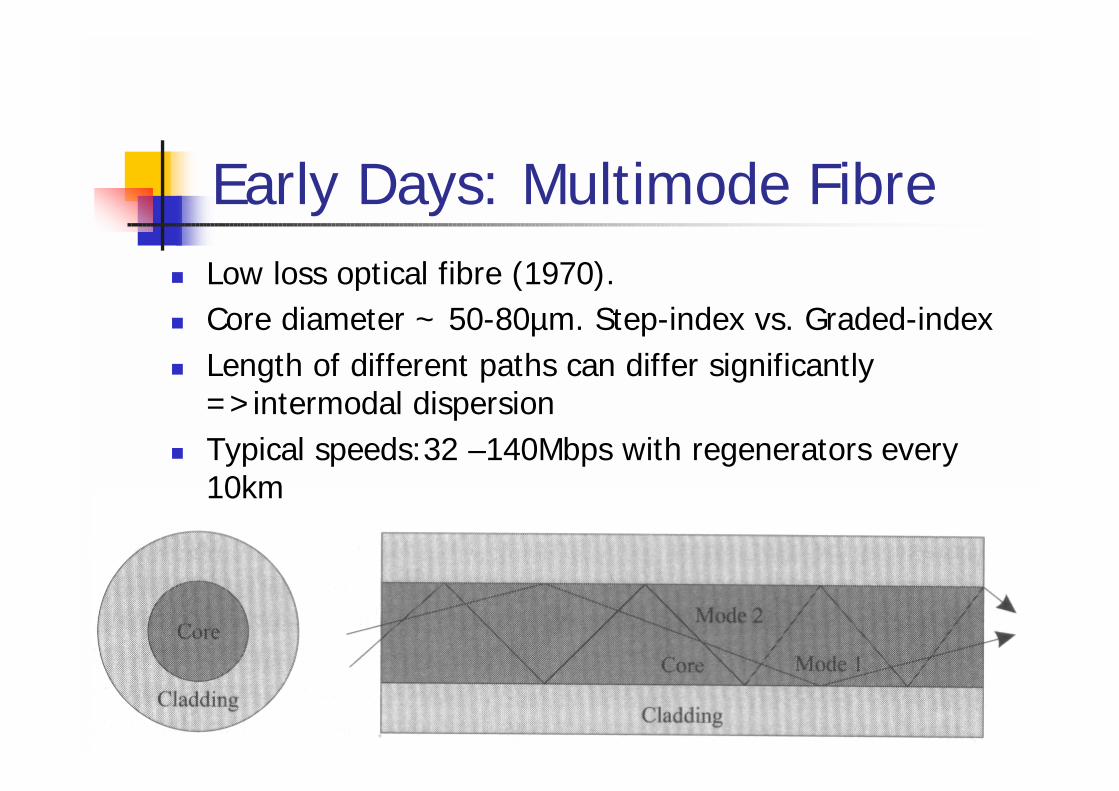
Early Days: Multimode Fibre! Low loss optical fibre (1970).! Core diameter ~ 50-80µm. Step-index vs. Graded-index! Length of different paths can differ significantly
=>intermodal dispersion! Typical speeds:32 –140Mbps with regenerators every
10km

Gergely Zaruba - CSE6344 Fall 2001
Early Days: LEDs! Through the early 80s.! 0.8 and 1.3µm wavelengths.! But light emission power was low while
spectrum was to wide (x*10nm).! MLM (multilongitudinal mode) Fabry-Perot
lasers have higher power but still transmit over a broad spectrum (hence the name) (note, spectrum is not continuous like with LEDs but ensembles periodic lines).
! Frequent regenerations were needed (every few km-s).

Gergely Zaruba - CSE6344 Fall 2001
Single-Mode Fibre! Starting 1984 single-mode fibre was
commercially available (driven yet by MLM lasers at 1300nm).
! Relatively small core diameter (8-10µm) closer to the wavelength, forcing signals to travel in a single mode.
! => No intermodal dispersion, dramatic increase in bit rates (>100Mbps) and distances (>40km).

Gergely Zaruba - CSE6344 Fall 2001
Longer Wavelengths! 1550 nm lasers are available.! Fibre loss is significantly less in this
band => longer distances w/o regeneration.
! Chromatic dispersion becomes a problem (different wavelengths travel with a different speed). (Ironically chromatic dispersion is not present at 1300nm but is significant at 1550nm.)

Gergely Zaruba - CSE6344 Fall 2001
Dispersion Shifted Fibre! Goal: to reduce (make it zero)
chromatic dispersion in the 1550nm band.
! But at that time already too many simple single-mode fibres were deployed. Another technique was needed to reduce chromatic dispersion in the 1550nm band.

Gergely Zaruba - CSE6344 Fall 2001
Narrowing the Spectrum of Lasers (SLM Lasers)! The bandwidth of the transmitted pulse is at
least equal to to its modulation bandwidth.! But MLM Fabry-Perot laser’s spectrum was
way far more (hundreds of GHz) than the modulation bandwidth.
! Distributed Feedback (DFB) laser was developed (a DFB laser is a single-longitudinal laser (SLM)).
! Using DFB the bit rate in the 1550nm band can reach several Gbps.

Gergely Zaruba - CSE6344 Fall 2001
Optical Amplifiers! Development of Erbium-Doped Fibre Amplifiers (EDFA)
in the late 1980s, early 1990s. (Theory was invented in the 1960s)
! Erbium atoms (a rare earth element) are doped into the fibre. Then they are “pumped” with a pump source to an “excited state” (high energy level).
! Erbium atoms are triggered back to normal state by incoming photons while emitting photons themselves.
! Pumping is done by a low-wavelength pump laser source (lower wavelength => higher energy ; this is needed to transfer energy to lower energy photons).
! Coincidentally Erbium works great in the 1550nm band.
Gergely Zaruba - CSE6344 Fall 2001
EDFA! Enables new generations of systems.! They are capable to amplify signals at many
different wavelengths simultaneously, thus EDFAs enable efficient use of WDM technology.
! Number of regenerators is significantly reduced => cost of long haul transmissions is greatly reduced (orders of magnitude).
! With WDM new connections can be brought up quickly (no need to deploy fibre ahead).

Gergely Zaruba - CSE6344 Fall 2001
EDFA vs. Chromatic Dispersion! With the use of EDFAs, chromatic
dispersion became an important issue again.
! Solution: External modulator devices for lasers (instead of turning the lasers on and off). Speeds of 2.5Gbps per channel and distances over 600km are possible.

Gergely Zaruba - CSE6344 Fall 2001
By Solving a Problem New Problems Arise
! Chromatic dispersion compensation techniques enable 10Gbps communication over the same distances.
! Second and third-order problems become significant:! Non-linear effects of fibres (e.g., four wave mixing
(FWM, where 3 signals spawn a 4th)! Non-flat gain spectrum of EDFAs! Polarization related effects

Gergely Zaruba - CSE6344 Fall 2001
Today! New varieties of single mode fibres (less
chromatic dispersion with less non-linear effects (almost a contradiction)).
! Hundreds of channel with 10Gbps and 50GHz spacing over a few thousand km-s between regenerators.
! Total capacities of >10Tbs (research labs) with 40Gbps channels.(Today EDFAs work in the C and L band.)

Gergely Zaruba - CSE6344 Fall 2001
Future?! Development of amplifiers that work over different bands
(e.g., Raman amplification) (S and U band)! Development of new fibres that have good loss in other bands
too (E band ; no amps yet). Total bandwidth: 2*108/((1675-1260)*10-9) ~= 48THz
1625-1675Ultra-longU
1565-1625LongL1530-1565ConventionalC1460-1530ShortS
1360-1460ExtendedE1260-1360OriginalO
λ range (nm)DescriptorBand
Gergely Zaruba - CSE6344 Fall 2001
Using the Fibre! First generation optical networks emerged in
the 1980s.! Metro networks and optical interfaces are
deployed:! FDDI (Fibre Distributed Data Interface) (100Mbps)! ESCON (Enterprise Serial Connection) (200Mbps)! Today: Fibre Channel for storage networking
(Gbps).
! Mass deployment of SONET/SDH
Gergely Zaruba - CSE6344 Fall 2001
Using the Fibre! Second generation networks evolved
(Optical Layer).! Wavelength Routing Networks.! Lightpath on demand.! Fibre to the Home (FTTH), Fibre to the
Curb (FTTC) become reality. Fibre is getting closer to “us”.
! Fibre is used as the backbone for many large companies, universities.