Introduction to optical microscopy microscopy_spring 2019.pdfINTRODUCTION TO OPTICAL . MICROSCOPY -...
17
Experimental Biophysics TEK265, FYST23, TNF060, FAF010F Lab Exercise Supervisor: Pradheebha Surendiran [email protected] Written by Peter Jönsson and Jason Beech Updated by Henrik Persson, Karl Adolfsson and Zhen Li INTRODUCTION TO OPTICAL MICROSCOPY
Transcript of Introduction to optical microscopy microscopy_spring 2019.pdfINTRODUCTION TO OPTICAL . MICROSCOPY -...

Experimental Biophysics TEK265, FYST23, TNF060, FAF010F Lab Exercise Supervisor: Pradheebha Surendiran [email protected] Written by Peter Jönsson and Jason Beech Updated by Henrik Persson, Karl Adolfsson and Zhen Li
INTRODUCTION TO OPTICAL
MICROSCOPY

- 1 -
Dutch spectacle maker, Zacharias Janssen claimed to have invented the compound microscope more than 400 years ago although it was Anton van Leeuwenhoek that brought microscopes to the attention of biologists. Van Leeuwenhoek himself used the microscope to great effect discovering the hitherto invisible world of microorganisms and cells and is known therefore as the "Father of Microbiology". The optical microscope remains an invaluable tool for biologists, chemists and physicists alike. Despite numerous improvements in performance and usability, the basic principles behind the optical microscope are the same today as 400 years ago. The purpose of this laboratory exercise is for you to get an understanding of these principles and to get acquainted with a modern optical microscope.
Figure 1. Janssen’s microscope (left) and Van Leeuwenhoek’s microscope(right). Images from http://micro.magnet.fsu.edu/primer/museum/janssen.html and
http://micro.magnet.fsu.edu/primer/museum/leeuwenhoek.html respectively.
THE OPTICAL LENS The basic building block of an optical microscope is the lens. Lenses come in a wide variety of sizes and shapes, but the two most common lens types are the convex lens (see Figure 2 a) and the concave lens (see Figure 2b).
(a) (b) Figure 2. (a) A convex lens is thickest in the middle. Light that is travelling parallel to the optical axis of the lens
will be focused at the focal point after the lens. (b) A concave lens is thinnest at the middle. Light that is travelling parallel to the optical axis of the lens will diverge after passing the lens. The light will then appear to
come from the focal point in front of the lens. A lens refracts the light coming from an object, thus producing an image with a different size and position than the original object. Figure 3a shows the image from an object that has been placed a distance S1 in front of a convex lens. The observer looks through the lens from the right side of Figure 3.

- 2 -
(a) (b)
Figure 3. (a) An object placed a distance S1 in front of a convex lens produces a real image of the object if S1 > f. (b) If S1 < f then the image cannot be projected on a screen and is called a virtual image. This image will, for an observer to the right of the lens, look like it came from the position S2 in front of the lens. This is the principle
behind a magnifying glass.
The following relation can be derived between the focal length, f, the distance S1 from the object to the lens and the distance S2 from the lens to the image:
fSS111
21
=+ (1)
Eq. 1 is called the Gaussian lens formula, where S2 is positive to the right of the lens and negative to the left. A positive value of S2 will yield a real image of the object that can be projected on a screen after the lens (see Figure 3 a). If instead S2 is negative then the image looks like it came from a point to the left of the lens. An observer to the right of the lens will therefore see a magnified virtual image of the object at the new position S2 (see Figure 3b). This is the principle behind a magnifying glass. In reality a simple lens such as those depicted in Figure 2 and Figure 3 do not produce perfect images of an object, due to non-idealities in the lens. These non-idealities, or errors, are called aberrations and may be due to several different effects. The two most usual aberrations are spherical and chromatic aberration (see Figure 4).
(a) (b) Figure 4. (a) The effect of spherical aberration on the focusing of light. (b) Chromatic aberration causes light
with different wavelengths to become focused at different distances from the lens.

- 3 -
Spherical aberrations arise when light at the edge of the lens focuses at a different position than light traveling through the centre of the lens (see Figure 4a). This is related to the actual shape of the lens at different positions. Chromatic aberration is an artifact caused by the fact that the lens material may have a different index of refraction for different wavelengths. These wavelengths will then have different focal points (see Figure 4b). When imaging an object it is desirable that the object is imaged in a plane. However, due to the curvature of the lens, the image will in reality have a bent shape which gives rise to a distortion of the image when projected on a plane screen. All these effects are in practice compensated for by making compound lens system consisting of different types and combinations of lenses.
A SIMPLE OPTICAL MICROSCOPE A simple optical microscope can be constructed by two convex lenses and a light source that illuminates the sample. Figure 5 shows the lens configuration together with the image of the object at different positions in the microscope. The objective produces a real and inverted image of the object situated at the field stop (diaphragm), which regulates the maximum size of the object that is visualized. The light from this image then passes through an eyepiece (ocular), which works like a magnifying glass. By placing the focal plane of the eyepiece at the field stop, the virtual image created will look like it comes from infinity. This is the focus distance for a resting eye, thus the image can be comfortably viewed by the eye. The magnification of the microscope is the ratio of the size of the retinal image, as seen through the microscope, over the size of the retinal image as seen by the unaided eye. The total magnification will be the product of the magnification of the objective and the eyepiece. Both the objective and the eyepiece can easily be interchanged in a real microscope, thus altering the magnification of the system.
Figure 5. Schematic of a rudimentary optical microscope.
Instead of looking at the magnified object directly with the eye it is often practical to be able to acquire a picture of the image, or a movie sequence of images taken in succession. This can be done by placing a camera after the eyepiece in Figure 5.Figure 5 Schematic of a

- 4 -
rudimentary optical microscope. A common camera for acquiring both movie sequences and single images is the CCD camera. The CCD camera consists of a two-dimensional array of light sensitive elements, which are called pixels. When a photon impinges on a pixel it will induce a charge separation in the pixel, creating one electron-hole pair from each absorbed photon. Depending on how many photons that have hit the different pixels, the individual pixels will have different charge, referred to as photoelectrons. The charge for each pixel can subsequently be read and transferred to a computer building up an image of the charge at each pixel. Since the number of photons impinging on a pixel is proportional to the intensity of the light at that pixel, this will give an image of the object projected on the surface of the CCD camera.
KÖHLER ILLUMINATION When illuminating the samples with a light bulb why is it that the filament of the light bulb is not seen in the image? The answer to that question is that the filament of the lamp and the specimen are focused in different planes in the microscope (see Figure 6). This is the principle behind Köhler illumination.
Figure 6. Illustration of the two sets of conjugate planes in an optical microscope. The red rays are images of the filament, while the yellow rays are images of the specimen. The image of the specimen is focused at the image
plane, and can thus be sharply visualized, while the filament is not in focus at the image plane.

- 5 -
THE CHARACTERISTICS OF AN OBJECTIVE The objective is one of the most important, and complicated, parts of a microscope. However, in principle it is just a simple lens, as depicted in Figure 5. The reason for the complexity is that the objective consists of different parts that compensate for the aberrations usually seen in an ordinary lens. Figure 7 shows a typical dry objective with its different specifications. Dry refers to the air between the objective and the sample. Other types of objectives are constructed for having water or oil between the front lens and the sample. These types of objectives are called immersion objectives and can produce a higher resolution in the images, since they have a greater numerical aperture (NA) for a given size of the front lens (see Eq. 2).
Figure 7. An image of a 60x Plan Apochromat
objective with specifications.
The different markings on the objective seen in Figure 7 specify its properties. The meaning of some of these specifications is briefly described below. Flat-Field Correction and Aberration Correction: Plan means that the objective is corrected for having a field curvature. Apo defines that the objective has the highest degree of correction for spherical and chromatic aberration. Another high degree of correction for spherical and chromatic aberration is termed Fluor. Lateral Magnification: The objective has in the current case a magnification of 60x, yielding an image that is 60 times larger than with an objective with magnification 1x. Numerical Aperture: The numerical aperture (NA) of an objective is a measure of how much light it can collect and how fine details it can resolve. A higher NA corresponds to more light being collected and allows finer details to be resolved. NA is defined according to Eq. 2. αsinNA ⋅= n (2) where n is the index of refraction of the medium between the front lens and the specimen and α is the half-angle of the maximum cone of light picked up by the lens (see Figure 8).

- 6 -
Figure 8. The collection of light from the sample for objectives with different NA.
Specialized Optical Properties: This indicates if the objective is optimized for certain special microscopy conditions. DIC means e.g. that the objective can be used for differential interference contrast microscopy. During the experimental part we will use such an objective. Cover Glass Thickness: The objective is compensated for having a glass slide between the sample and the objective with this thickness. This reduces the aberrations arising from having a cover glass with a different index of refraction than the surrounding medium. Working Distance: This is the distance between the front lens of the objective and the top of the cover glass when the sample is in focus. Some objectives have the designation ELWD, which means that they have extra-long working distance. A high magnification often means that the working distance is low.
THE RESOLUTION OF AN OPTICAL MICROSCOPE The resolution of an optical microscope is the shortest real distance between two objects that are separable on the microscope image (see Figure 9).
Figure 9. The lateral resolution is defined as the shortest distance between which two of the Airy disks can be
separated. However, note that an individual object, with a smaller size than the resolution limit, can still be visualized in the microscope even though its size cannot be accurately determined.
Light transmitted through a circular aperture will have a characteristic diffraction pattern consisting of circles with alternating low and high intensity. The inner disk is called the Airy disk. For a simple lens it can be shown that the resolution, d, is determined by the wavelength of the incident light, λ, and the numerical aperture, NA, of the objective according to Eq. 3.
- 7 -
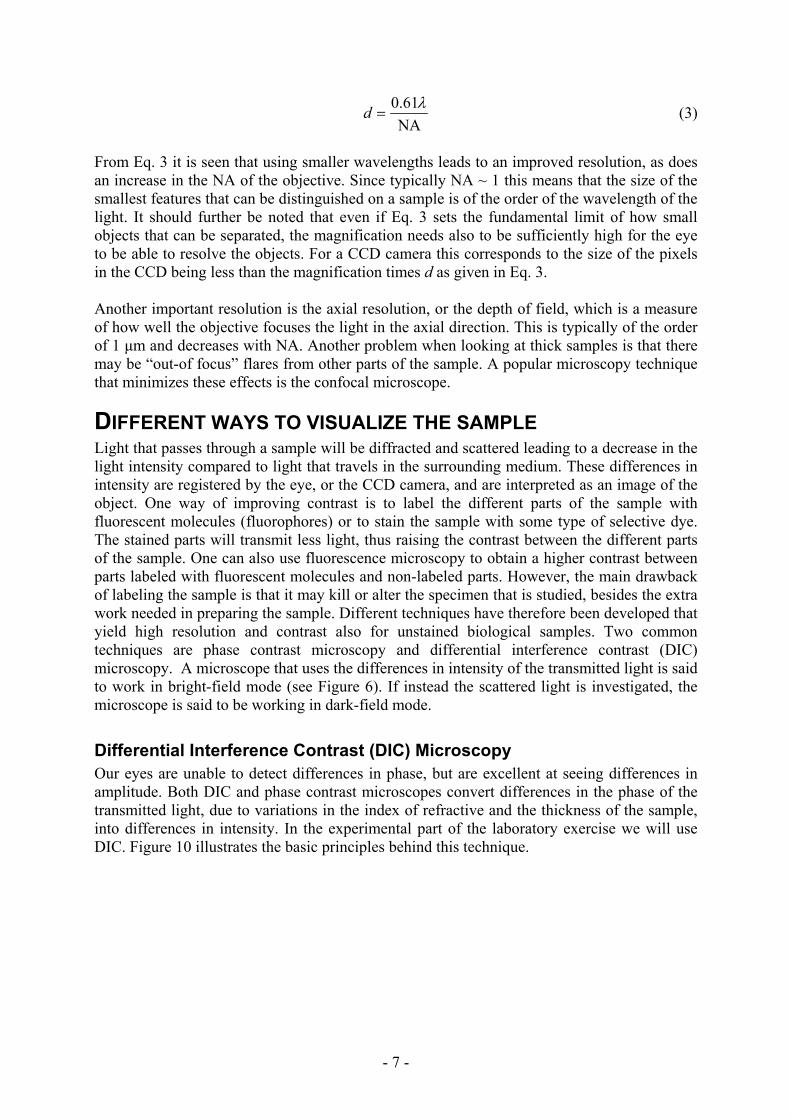
NA61.0 λ
=d (3)
From Eq. 3 it is seen that using smaller wavelengths leads to an improved resolution, as does an increase in the NA of the objective. Since typically NA ~ 1 this means that the size of the smallest features that can be distinguished on a sample is of the order of the wavelength of the light. It should further be noted that even if Eq. 3 sets the fundamental limit of how small objects that can be separated, the magnification needs also to be sufficiently high for the eye to be able to resolve the objects. For a CCD camera this corresponds to the size of the pixels in the CCD being less than the magnification times d as given in Eq. 3. Another important resolution is the axial resolution, or the depth of field, which is a measure of how well the objective focuses the light in the axial direction. This is typically of the order of 1 μm and decreases with NA. Another problem when looking at thick samples is that there may be “out-of focus” flares from other parts of the sample. A popular microscopy technique that minimizes these effects is the confocal microscope.
DIFFERENT WAYS TO VISUALIZE THE SAMPLE Light that passes through a sample will be diffracted and scattered leading to a decrease in the light intensity compared to light that travels in the surrounding medium. These differences in intensity are registered by the eye, or the CCD camera, and are interpreted as an image of the object. One way of improving contrast is to label the different parts of the sample with fluorescent molecules (fluorophores) or to stain the sample with some type of selective dye. The stained parts will transmit less light, thus raising the contrast between the different parts of the sample. One can also use fluorescence microscopy to obtain a higher contrast between parts labeled with fluorescent molecules and non-labeled parts. However, the main drawback of labeling the sample is that it may kill or alter the specimen that is studied, besides the extra work needed in preparing the sample. Different techniques have therefore been developed that yield high resolution and contrast also for unstained biological samples. Two common techniques are phase contrast microscopy and differential interference contrast (DIC) microscopy. A microscope that uses the differences in intensity of the transmitted light is said to work in bright-field mode (see Figure 6). If instead the scattered light is investigated, the microscope is said to be working in dark-field mode.
Differential Interference Contrast (DIC) Microscopy Our eyes are unable to detect differences in phase, but are excellent at seeing differences in amplitude. Both DIC and phase contrast microscopes convert differences in the phase of the transmitted light, due to variations in the index of refractive and the thickness of the sample, into differences in intensity. In the experimental part of the laboratory exercise we will use DIC. Figure 10 illustrates the basic principles behind this technique.

- 8 -
Figure 10. Schematic of a DIC microscope.

- 9 -
The basic idea behind DIC is that prisms and polarizing filters are used to create pairs of light rays that are shifted laterally with regard to each other by about 0.2µm. After passing through the sample these rays are then recombined. Because they pass through different parts of the sample, any difference in optical path length (index of refraction x thickness) creates a relative phase shift within each pair. When recombined the pairs of rays interfere with each other and the phase shift is converted to an amplitude variation that we can see. Another way to think of DIC is that two bright field images are created with a small (0.2µm) shift between them and that they are consequently allowed to interfere with each other. Any difference in optical path length within the 0.2µm shift at each point in the image will show up as brighter of darker in the image. This means that the edges of objects become very clear if the DIC is correctly set up.
Fluorescence microscopy If a molecule adsorbs light at a certain wavelength (excitation) and re-radiates the light at another wavelength (emission), the molecule is said to be fluorescent. In which interval the fluorescent molecule adsorbs and emits light depends on the type of molecule and the surroundings. The major advantage of using fluorescent molecules is that light from non-fluorescent material of the sample can be filtered out, only keeping the light from the labeled specimen. The drawback is that the sample needs to be marked with fluorescent molecules. The most common fluorescence microscope is the epi-fluorescence microscope, characterized by both exciting and observing the fluorophores on the same side of the microscope (see Figure 11). (Illumination and detection on opposite sides of the objective is called dia-illumination.) Light consisting of all wavelengths is incident on the filter cube in Figure 11. An excitation filter first filters out the light that is used to excite the studied fluorophores in the sample. The dichroic mirror reflects the excitation light toward the sample. The dichroic mirror has the property that it reflects most of the light below a certain wavelength while transmitting the majority of the light above this wavelength, thereby being a good mirror for the excitation and a good window for the emission wavelengths. For the filter cube this wavelength is chosen to be between the excitation and emission wavelengths of the filters. Light coming from the sample can now be categorized into two classes:
Figure 11. The principles behind epi-
fluorescence microscopy, where obj. stands for the objective. Excitation and emission filter as well as the dichroic mirror is in practice placed in one unit called the filter cube (dashed lines).
1) Light that is elastically scattered with the same wavelength as the excitation light. 2) Emitted fluorescent light with a longer wavelength than the excitation light. The elastically scattered light can come from different parts of the sample while the fluorescent light comes only from the labeled molecules. Thus, by filtering out only the fluorescent light the contrast of the specimen can be increased many times. This filtering is primarily done by the emission filter (the dichroic mirror transmits roughly 20% of the excitation light as compared to the emission filter which typically transmits 10-5 of the excitation light). Thus, essentially only the fluorescent light will reach the detector.

- 10 -
OUR MICROSCOPE – NIKON TE2000 The microscope that you will use in the laboratory exercises in this course is a Nikon TE2000-U. An image of a standard Nikon TE2000-U is shown in Figure 12 together with the names of the different parts of the microscope.
Figure 12. The different parts of a standard Nikon TE2000-U microscope.
In addition to what is seen in Figure 12 the microscope that you will use also have: • A 512×512 pixels (square pixels, each side is 16µm) CCD camera (iXon 897).
• A super-high pressure mercury lamp for epi-fluorescence measurements, mounted on the rear of the microscope.
• A cassette with different filter cubes.
• An xy-stage to move the sample with a joy-stick with μm precision

- 11 -
EXPERIMENTAL PART The experimental session of this laboratory exercise will be divided into a few small experiments; detection of different types of fluorescent beads using epi-fluorescence microscopy and visualization of human cells from the cheek using DIC microscopy. There will also be an interesting sample of fluorescently labeled cells and you will get to assemble your own fluorescence microscope as a warm up exercise (not described in this handout).
Fluorescence microscopy - Fluorescent beads Polystyrene particles labeled with different kinds of fluorescent dyes can by bought in a wide variety of sizes. In this exercise we will look at a sample consisting of two kinds of beads: beads with a diameter of 0,25 μm fluorescent in blue and beads with a diameter of 0.71μm fluorescent in red. Your task will be to investigate a sample consisting of these two beads with an epi-fluorescence microscope.

- 12 -
Instructions
Be very careful not to damage the camera with high light intensity; turn down light before switching to camera and avoid saturating pixels. 1) Start the program Andor iQ which controls the acquisition of images from the
microscope. Choose “luca only” as user. 2) Make sure the CCD camera (Andor Luca, to the right of the microscope) is connected to
both the computer and a power source. 3) Switch on the xy-stage and the mercury lamp providing the illumination for the epi-
fluorescence microscope. 4) Mount a 20x dry objective. Set the cover glass adjustment to 0.17 mm, corresponding to
the thickness of the cover glass that we are going to use. 5) Take a new microscope slide and add 4 μL of the mixture of green and red heads. The
concentration of the blue beads and the red beads is 0.1 wt% of the mixture. 6) Put a standard cover glass on top of the drop and mount the sample on the stage with the
cover glass pointing down towards the objective. Center the objective with the xy-stage joystick so that its position corresponds to the position of the sample.
7) Choose a suitable filter cube from the lower cassette. There are three different filter cubes to choose from: TRITC, FITC and DAPI with the specifications in Table 1. Their excitation/emission spectra are present in the lab along with the spectra for the beads.
Table 1 Filter cube specifications. The excitation and emission filters transmit in the stated wavelength ranges. The dichroic mirror reflects/transmits the majority of light with a wavelength below/above the stated wavelength.
Excitation [nm] Dichroic mirror [nm] Emission [nm] TRITC 515-565 565 550-660 FITC 465-495 505 515-555 DAPI 340-380 400 435-485
8) Choose the correct camera in the software, (“Device Setup”>”Camera”>"Camera 2") 9) Set the optical path switch to 5. Start the acquisition of live images on the sample by
pushing the button “Live” in Andor iQ. Switching off the light in the room is advisable to get better contrast.
10) Adjust the focus to get a clear image. Check the working distance of the objective to get an appreciation of how close you should approach the sample. Make sure that you do not crash into the sample when raising the objective.
11) Test different filter cubes. Save the images using the “Snap” button in Andor iQ.
- 13 -
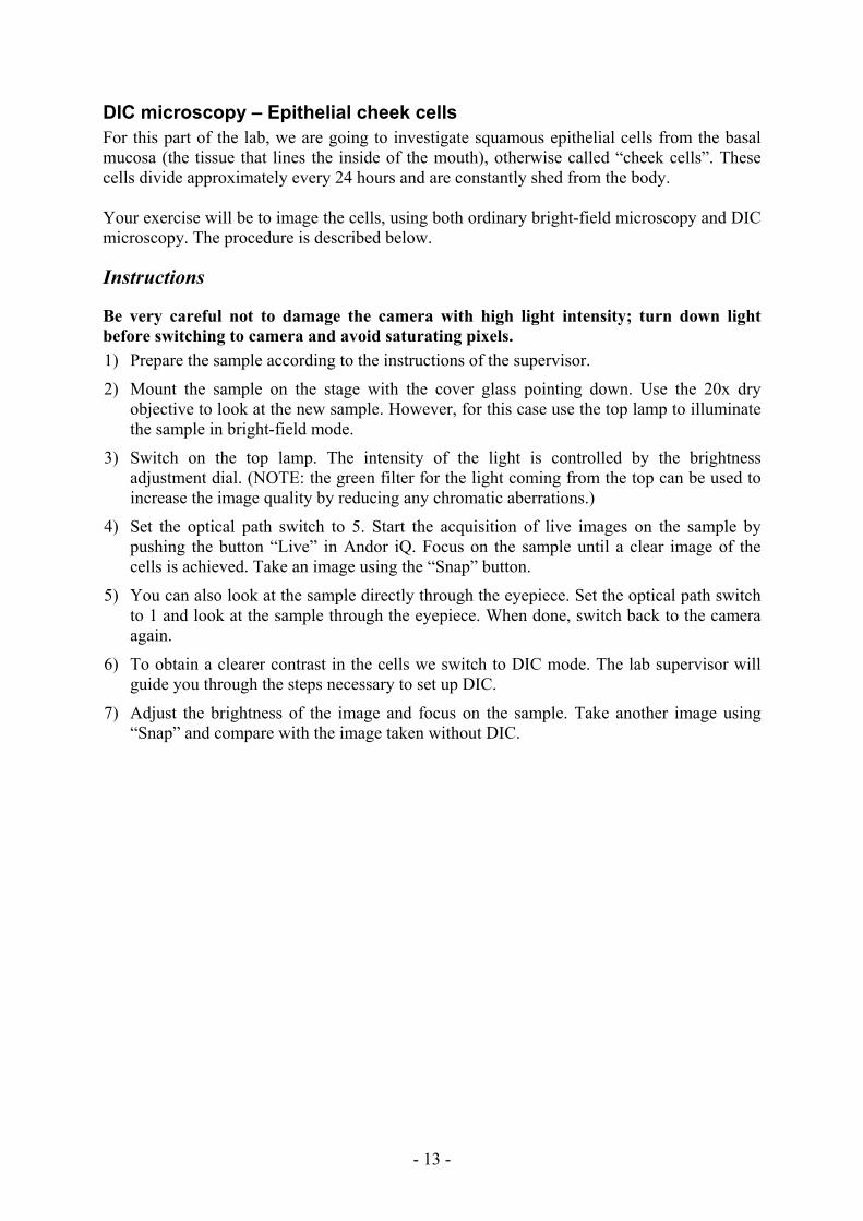
DIC microscopy – Epithelial cheek cells For this part of the lab, we are going to investigate squamous epithelial cells from the basal mucosa (the tissue that lines the inside of the mouth), otherwise called “cheek cells”. These cells divide approximately every 24 hours and are constantly shed from the body. Your exercise will be to image the cells, using both ordinary bright-field microscopy and DIC microscopy. The procedure is described below.
Instructions
Be very careful not to damage the camera with high light intensity; turn down light before switching to camera and avoid saturating pixels. 1) Prepare the sample according to the instructions of the supervisor. 2) Mount the sample on the stage with the cover glass pointing down. Use the 20x dry
objective to look at the new sample. However, for this case use the top lamp to illuminate the sample in bright-field mode.
3) Switch on the top lamp. The intensity of the light is controlled by the brightness adjustment dial. (NOTE: the green filter for the light coming from the top can be used to increase the image quality by reducing any chromatic aberrations.)
4) Set the optical path switch to 5. Start the acquisition of live images on the sample by pushing the button “Live” in Andor iQ. Focus on the sample until a clear image of the cells is achieved. Take an image using the “Snap” button.
5) You can also look at the sample directly through the eyepiece. Set the optical path switch to 1 and look at the sample through the eyepiece. When done, switch back to the camera again.
6) To obtain a clearer contrast in the cells we switch to DIC mode. The lab supervisor will guide you through the steps necessary to set up DIC.
7) Adjust the brightness of the image and focus on the sample. Take another image using “Snap” and compare with the image taken without DIC.

- 14 -
Fluorescence microscopy – fixated cell lines For this part of the lab, we will look at lung cancer cells treated with nanowires which has been used for cytotoxicity studies. Although nanowires exhibit interesting properties for science and engineering, we do not yet the extent which they might be harmful for humans or other lifeforms. As regular lung cells are difficult to culture in a lab, the nearest representation, lung cancer cells have been used. The cells were exposed to nanowires, 5 μm long and 40 μm in diameter and cell effects after encapsulation was studied. The cells have been fixed and stained with the DNA stain bizbensimide and the actin binding toxin phalloidin conjugated to the dye Alexa-488, see spectra below. Your task is to use the 60x water immersion objective to acquire images of the cells visualizing both dyes. During the lab exercise you will receive instructions on how to assemble the two black and white images into one multicolor image. You will also learn how to add an accurate scale bar. These skills will be very important during your project later in the course.
Figure 13. Fluorescence spectra for bisbenzimide (blue) and Alexa-488 (green).
Spectra acquired from Invitrogen’s Spectra viewer: http://www.invitrogen.com/site/us/en/home/support/Research-Tools/Fluorescence-SpectraViewer.html

- 15 -
Preparatory Questions The laboratory exercise will start with a 15 min written exam consisting of five questions. You will have to give satisfactory answers to at least three of these five questions to be allowed to continue the experimental part of the laboratory exercise. The questions will be chosen from the set of questions presented below.
Questions 1) What is the difference between a real and a virtual image when seen through a lens? 2) Mention two common errors for ordinary lenses when it comes to focusing the light. 3) Describe the principle behind a magnifying glass. 4) How is the magnification of a microscope defined? 5) Why is an image of the lamp filament not seen in the microscope images? 6) What is Köhler illumination? 7) What is a dry objective? What is an immersion objective? 8) From an image of an objective tell its: magnification, NA and working distance. 9) How is the numerical aperture (NA) of an objective defined? How is this related to the
amount of light collected by the objective? 10) What is the working distance of an objective? 11) What is the resolution of an optical microscope? 12) How is the lateral resolution of a microscope related to the wavelength of the light and the
NA of the objective? 13) Can you see an object that is smaller than the resolution limit? 14) What is the difference between bright-field and dark-field microscopy? 15) What gives the contrast in the image when using a standard bright-field microscope? 16) What gives the contrast in the image when using a DIC microscope? 17) How does a DIC microscope work? (You don't need to know all the details, an overview
will do.) 18) What is the advantage of using DIC in comparison to standard bright-field microscopy? 19) What is excitation and emission light for a fluorescent molecule? 20) How does an epi-fluorescence microscope work? Draw a sketch showing the optical path
of the light from the lamp to the detector. 21) What is the advantage/disadvantage of labeling the sample with fluorescent molecules?
- 16 -
KEY-POINTS When leaving this laboratory exercise you should hopefully feel a little bit more acquainted with a modern optical microscope and know the basic principles behind how a microscope works. The following five key-points are extra important for you to carry with you from this laboratory exercise: • You should have a basic knowledge about lenses and how they can produce an enlarged
image in a microscope. • You should know how an epi-fluorescence microscope works and how to choose a
suitable filter cube for a known fluorophore. • You should know the difference between DIC and standard bright-field microscopy. • You should know how the resolution and magnification of an objective limits how small
features you can distinguish in a sample. • You should know the basic handling of an optical microscope: how to choose and change
objective, how to use different sources of illumination, how to focus on the sample and how to acquire an image.
REFERENCES Below are some useful references for those of you who want to learn more about how an optical microscope works. These references may also be useful when it comes to answering the questions above: http://www.microscopyu.com/sitemap.html (08-02-26) http://en.wikipedia.org/wiki/Optical_microscope (08-02-26) Hecht, E. 1987. Optics. Addison-Wesley, Reading (Massachusetts)


![Near-Field Optical Microscopy - Indico [Home]indico.ictp.it/event/a04179/session/16/contribution/11/material/0/0.pdf · Optical microscopy Electron microscopy' Near-field optical](https://static.fdocuments.net/doc/165x107/5ed73d31d37f9f58ca6a86bf/near-field-optical-microscopy-indico-home-optical-microscopy-electron-microscopy.jpg)