
INTRODUCTION TO OPERATING SYSTEMS - Mu (IT) - Sem - III - Modern... · INTRODUCTION TO OPERATING...
192
1 INTRODUCTION TO OPERATING SYSTEMS Unit Structure 1.0 Objectives 1.1 Introduction 1.2 OS and computer system 1.3 System performance 1.4 Classes of operating systems 1.4.1 Batch processing systems 1.4.1.1 Simple batch systems 1.4.1.2 Multi-programmed batch systems 1.4.2 Time sharing systems 1.4.3 Multiprocessing systems 1.4.3.1 Symmetric multiprocessing systems 1.4.3.2 Asymmetric multiprocessing systems 1.4.4 Real time systems 1.4.4.1 Hard and soft real-time systems 1.4.4.2 Features of a real-time operating systems 1.4.5 Distributed systems 1.4.6 Desktop systems 1.4.7 Handheld systems 1.4.8 Clustered systems 1.5 Let us sum up 1.6 Unit end questions 1.0 OBJECTIVES After going through this unit, you will be able to: • Understand the fundamental concepts and techniques of operating systems. • Build a core knowledge of what makes an operating system tick.
Transcript of INTRODUCTION TO OPERATING SYSTEMS - Mu (IT) - Sem - III - Modern... · INTRODUCTION TO OPERATING...

1
INTRODUCTION TO OPERATINGSYSTEMS
Unit Structure1.0 Objectives1.1 Introduction1.2 OS and computer system1.3 System performance1.4 Classes of operating systems
1.4.1 Batch processing systems1.4.1.1 Simple batch systems1.4.1.2 Multi-programmed batch systems
1.4.2 Time sharing systems1.4.3 Multiprocessing systems
1.4.3.1 Symmetric multiprocessing systems1.4.3.2 Asymmetric multiprocessing systems
1.4.4 Real time systems1.4.4.1 Hard and soft real-time systems1.4.4.2 Features of a real-time operating systems
1.4.5 Distributed systems1.4.6 Desktop systems1.4.7 Handheld systems1.4.8 Clustered systems
1.5 Let us sum up1.6 Unit end questions
1.0 OBJECTIVES
After going through this unit, you will be able to:• Understand the fundamental concepts and techniques of
operating systems.• Build a core knowledge of what makes an operating system
tick.
• Identify various classes of operating systems and distinguishbetween them.
1.1 INTRODUCTION
Each user has his own personal thoughts on what thecomputer system is for. The operating system, or OS, as we willoften call it, is the intermediary between users and the computersystem. It provides the services and features present in abstractviews of all its users through the computer system.
An operating system controls use of a computer system’sresources such as CPUs, memory, and I/O devices to meetcomputational requirements of its users.
1.2 OS AND COMPUTER SYSTEM
In technical language, we would say that an individual user hasan abstract view of the computer system, a view that takes in onlythose features that the user considers important. To be morespecific, typical hardware facilities for which the operating systemprovides abstractions include:
• processors• RAM (random-access memory, sometimes known as primary
storage, primary memory, or physical memory)• disks (a particular kind of secondary storage)• network interface• display• keyboard• mouse
An operating system can also be commonly defined as “aprogram running at all times on the computer (usually called thekernel), with all other being application programs”.
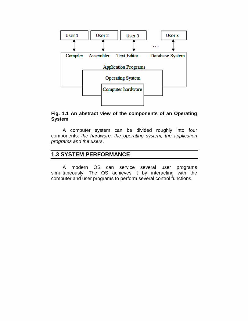
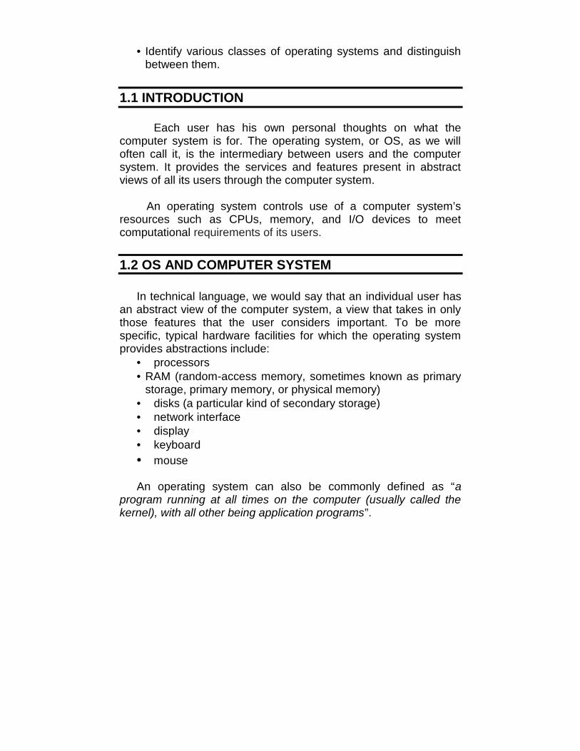
Fig. 1.1 An abstract view of the components of an OperatingSystem
A computer system can be divided roughly into fourcomponents: the hardware, the operating system, the applicationprograms and the users.
1.3 SYSTEM PERFORMANCE
A modern OS can service several user programssimultaneously. The OS achieves it by interacting with thecomputer and user programs to perform several control functions.
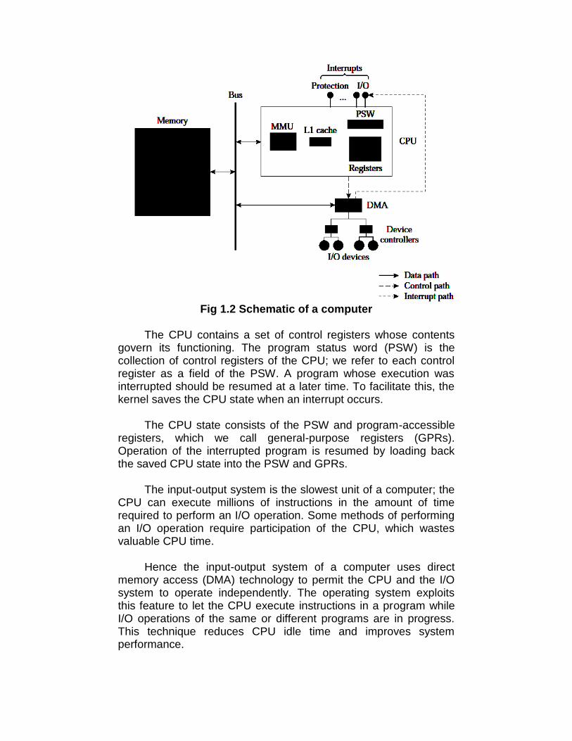
Fig 1.2 Schematic of a computer
The CPU contains a set of control registers whose contentsgovern its functioning. The program status word (PSW) is thecollection of control registers of the CPU; we refer to each controlregister as a field of the PSW. A program whose execution wasinterrupted should be resumed at a later time. To facilitate this, thekernel saves the CPU state when an interrupt occurs.
The CPU state consists of the PSW and program-accessibleregisters, which we call general-purpose registers (GPRs).Operation of the interrupted program is resumed by loading backthe saved CPU state into the PSW and GPRs.
The input-output system is the slowest unit of a computer; theCPU can execute millions of instructions in the amount of timerequired to perform an I/O operation. Some methods of performingan I/O operation require participation of the CPU, which wastesvaluable CPU time.
Hence the input-output system of a computer uses directmemory access (DMA) technology to permit the CPU and the I/Osystem to operate independently. The operating system exploitsthis feature to let the CPU execute instructions in a program whileI/O operations of the same or different programs are in progress.This technique reduces CPU idle time and improves systemperformance.
1.4 CLASSES OF OPERATING SYSTEMS
Classes of operating systems have evolved over time ascomputer systems and users’ expectations of them havedeveloped; i.e., as computing environments have evolved.
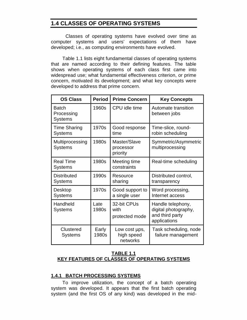
Table 1.1 lists eight fundamental classes of operating systemsthat are named according to their defining features. The tableshows when operating systems of each class first came intowidespread use; what fundamental effectiveness criterion, or primeconcern, motivated its development; and what key concepts weredeveloped to address that prime concern.
OS Class Period Prime Concern Key Concepts
BatchProcessingSystems
1960s CPU idle time Automate transitionbetween jobs
Time SharingSystems
1970s Good responsetime
Time-slice, round-robin scheduling
MultiprocessingSystems
1980s Master/Slaveprocessorpriority
Symmetric/Asymmetricmultiprocessing
Real TimeSystems
1980s Meeting timeconstraints
Real-time scheduling
DistributedSystems
1990s Resourcesharing
Distributed control,transparency
DesktopSystems
1970s Good support toa single user
Word processing,Internet access
HandheldSystems
Late1980s
32-bit CPUswithprotected mode
Handle telephony,digital photography,and third partyapplications
ClusteredSystems
Early1980s
Low cost µps,high speednetworks
Task scheduling, nodefailure management
TABLE 1.1KEY FEATURES OF CLASSES OF OPERATING SYSTEMS
1.4.1 BATCH PROCESSING SYSTEMSTo improve utilization, the concept of a batch operating
system was developed. It appears that the first batch operatingsystem (and the first OS of any kind) was developed in the mid-
1950s by General Motors for use on an IBM 701 [WEIZ81]. Theconcept was subsequently refined and implemented on the IBM704 by a number of IBM customers. By the early 1960s, a numberof vendors had developed batch operating systems for theircomputer systems. IBSYS, the IBM operating system for the7090/7094 computers, is particularly notable because of itswidespread influence on other systems.
In a batch processing operating system, the prime concern isCPU efficiency. The batch processing system operates in a strictone job-at-a-time manner; within a job, it executes the programsone after another. Thus only one program is under execution at anytime.
The opportunity to enhance CPU efficiency is limited toefficiently initiating the next program when one program ends, andthe next job when one job ends, so that the CPU does not remainidle.
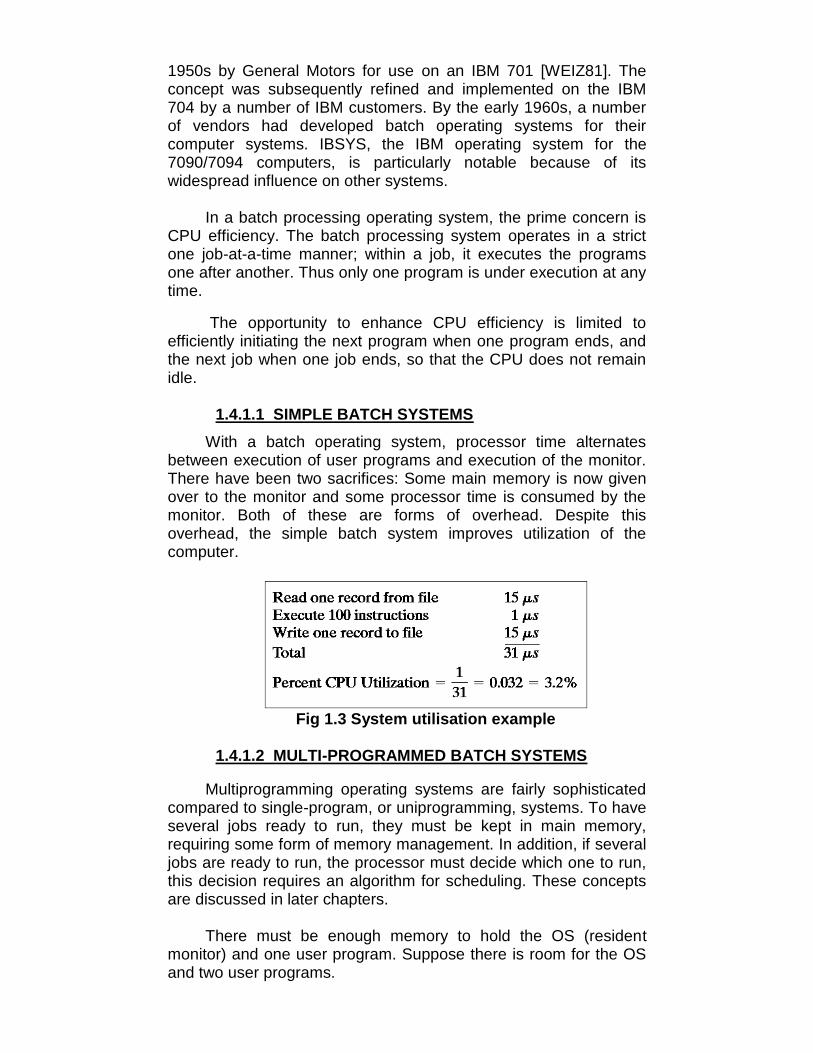
1.4.1.1 SIMPLE BATCH SYSTEMSWith a batch operating system, processor time alternates
between execution of user programs and execution of the monitor.There have been two sacrifices: Some main memory is now givenover to the monitor and some processor time is consumed by themonitor. Both of these are forms of overhead. Despite thisoverhead, the simple batch system improves utilization of thecomputer.
Fig 1.3 System utilisation example
1.4.1.2 MULTI-PROGRAMMED BATCH SYSTEMS
Multiprogramming operating systems are fairly sophisticatedcompared to single-program, or uniprogramming, systems. To haveseveral jobs ready to run, they must be kept in main memory,requiring some form of memory management. In addition, if severaljobs are ready to run, the processor must decide which one to run,this decision requires an algorithm for scheduling. These conceptsare discussed in later chapters.
There must be enough memory to hold the OS (residentmonitor) and one user program. Suppose there is room for the OSand two user programs.

When one job needs to wait for I/O, the processor can switchto the other job, which is likely not waiting for I/O (Figure 1.4(b)).Furthermore, we might expand memory to hold three, four, or moreprograms and switch among all of them (Figure 1.4(c)). Theapproach is known as multiprogramming, or multitasking. It is thecentral theme of modern operating systems.
Fig 1.4 Multiprogramming Example
This idea also applies to real life situations. You do not haveonly one subject to study. Rather, several subjects may be in theprocess of being served at the same time. Sometimes, beforestudying one entire subject, you might check some other subject toavoid monotonous study. Thus, if you have enough subjects, younever need to remain idle.

1.4.2 TIME SHARING SYSTEMSA time-sharing operating system focuses on facilitating quick
response to subrequests made by all processes, which provides atangible benefit to users. It is achieved by giving a fair executionopportunity to each process through two means: The OS servicesall processes by turn, which is called round-robin scheduling. It alsoprevents a process from using too much CPU time when scheduledto execute, which is called time-slicing. The combination of thesetwo techniques ensures that no process has to wait long for CPUattention.
1.4.3 MULTIPROCESSING SYSTEMSMany popular operating systems, including Windows and
Linux, run on multiprocessors. Multiprocessing sometimes refers tothe execution of multiple concurrent software processes in asystem as opposed to a single process at any one instant.However, the terms multitasking or multiprogramming are moreappropriate to describe this concept, which is implemented mostlyin software, whereas multiprocessing is more appropriate todescribe the use of multiple hardware CPUs. A system can be bothmultiprocessing and multiprogramming, only one of the two, orneither of the two.
Systems that treat all CPUs equally are called symmetricmultiprocessing (SMP) systems. In systems where all CPUs are notequal, system resources may be divided in a number of ways,including asymmetric multiprocessing (ASMP), non-uniformmemory access (NUMA) multiprocessing, and clusteredmultiprocessing.
1.4.3.1 SYMMETRIC MULTIPROCESSING SYSTEMS
Symmetric multiprocessing or SMP involves amultiprocessor computer architecture where two or more identicalprocessors can connect to a single shared main memory. Mostcommon multiprocessor systems today use an SMP architecture.
In the case of multi-core processors, the SMP architectureapplies to the cores, treating them as separate processors. SMPsystems allow any processor to work on any task no matter wherethe data for that task are located in memory; with proper operatingsystem support, SMP systems can easily move tasks betweenprocessors to balance the workload efficiently.

Fig 1.5 A typical SMP system
1.4.3.2 ASYMMETRIC MULTIPROCESSING SYSTEMS
Asymmetric hardware systems commonly dedicatedindividual processors to specific tasks. For example, one processormay be dedicated to disk operations, another to video operations,and the rest to standard processor tasks .These systems don't havethe flexibility to assign processes to the least-loaded CPU, unlikean SMP system.
Unlike SMP applications, which run their threads on multipleprocessors, ASMP applications will run on one processor butoutsource smaller tasks to another. Although the system mayphysically be an SMP, the software is still able to use it as anASMP by simply giving certain tasks to one processor and deemingit the "master", and only outsourcing smaller tasks to "slave"processors.
Fig 1.6 Multiple processors with unique access to memory andI/O
1.4.4 REAL TIME SYSTEMSA real-time operating system is used to implement a computer
application for controlling or tracking of real-world activities. Theapplication needs to complete its computational tasks in a timelymanner to keep abreast of external events in the activity that itcontrols. To facilitate this, the OS permits a user to create severalprocesses within an application program, and uses real-timescheduling to interleave the execution of processes such that theapplication can complete its execution within its time constraint.
1.4.4.1 HARD AND SOFT REAL-TIME SYSTEMSTo take advantage of the features of real-time systems while
achieving maximum cost-effectiveness, two kinds of real-timesystems have evolved.
A hard real-time system is typically dedicated to processingreal-time applications, and provably meets the responserequirement of an application under all conditions.
A soft real-time system makes the best effort to meet theresponse requirement of a real-time application but cannotguarantee that it will be able to meet it under all conditions. Digitalaudio or multimedia systems fall in this category. Digital telephonesare also soft real-time systems.
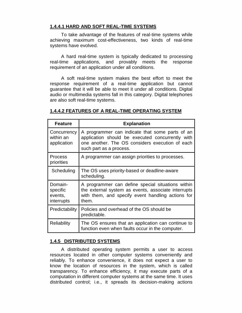
1.4.4.2 FEATURES OF A REAL-TIME OPERATING SYSTEM
Feature Explanation
Concurrencywithin anapplication
A programmer can indicate that some parts of anapplication should be executed concurrently withone another. The OS considers execution of eachsuch part as a process.
Processpriorities
A programmer can assign priorities to processes.
Scheduling The OS uses priority-based or deadline-awarescheduling.
Domain-specificevents,interrupts
A programmer can define special situations withinthe external system as events, associate interruptswith them, and specify event handling actions forthem.
Predictability Policies and overhead of the OS should bepredictable.
Reliability The OS ensures that an application can continue tofunction even when faults occur in the computer.
1.4.5 DISTRIBUTED SYSTEMSA distributed operating system permits a user to access
resources located in other computer systems conveniently andreliably. To enhance convenience, it does not expect a user toknow the location of resources in the system, which is calledtransparency. To enhance efficiency, it may execute parts of acomputation in different computer systems at the same time. It usesdistributed control; i.e., it spreads its decision-making actions

across different computers in the system so that failures ofindividual computers or the network does not cripple its operation.
A distributed operating system is one that appears to its usersas a traditional uniprocessor system, even though it is actuallycomposed of multiple processors. The users may not be aware ofwhere their programs are being run or where their files are located;that should all be handled automatically and efficiently by theoperating system.
True distributed operating systems require more than justadding a little code to a uniprocessor operating system, becausedistributed and centralized systems differ in certain critical ways.Distributed systems, for example, often allow applications to run onseveral processors at the same time, thus requiring more complexprocessor scheduling algorithms in order to optimize the amount ofparallelism.
1.4.6 DESKTOP SYSTEMSA desktop system is a personal computer (PC) system in a
form intended for regular use at a single location, as opposed to amobile laptop or portable computer. Early desktop computers weredesigned to lay flat on the desk, while modern towers stand upright.Most modern desktop computer systems have separate screensand keyboards.
Modern ones all support multiprogramming, often with dozensof programs started up at boot time. Their job is to provide goodsupport to a single user. They are widely used for word processing,spreadsheets, and Internet access. Common examples are Linux,FreeBSD, Windows 8, and the Macintosh operating system.Personal computer operating systems are so widely known thatprobably little introduction is needed.
1.4.7 HANDHELD SYSTEMSA handheld computer or PDA (Personal Digital Assistant) is a
small computer that fits in a shirt pocket and performs a smallnumber of functions, such as an electronic address book andmemo pad. Since these computers can be easily fitted on thepalmtop, they are also known as palmtop computers. Furthermore,many mobile phones are hardly any different from PDAs except forthe keyboard and screen. In effect, PDAs and mobile phones haveessentially merged, differing mostly in size, weight, and userinterface. Almost all of them are based on 32-bit CPUs withprotected mode and run a sophisticated operating system.
One major difference between handhelds and PCs is that theformer do not have multigigabyte hard disks, which changes a lot.

Two of the most popular operating systems for handhelds areSymbian OS and Android OS.
1.4.8 CLUSTERED SYSTEMSA computer cluster consists of a set of loosely connected
computers that work together so that in many respects they can beviewed as a single system.
The components of a cluster are usually connected to eachother through fast local area networks, each node (computer usedas a server) running its own instance of an operating system.Computer clusters emerged as a result of convergence of a numberof computing trends including the availability of low costmicroprocessors, high speed networks, and software for highperformance distributed computing.
In Clustered systems, if the monitored machine fails, themonitoring machine can take ownership of its storage, and restartthe application(s) that were running on the failed machine. Thefailed machine can remain down, but the users and clients of theapplication would only see a brief interruption of the service.
In asymmetric clustering, one machine is in hot standby modewhile the other is running the applications. The hot standby host(machine) does nothing but monitor the active server. If that serverfails, the hot standby host becomes the active server. In symmetricmode, two or more hosts are running applications, and they aremonitoring each other. It does require that more than oneapplication be available to run.
Other forms of clusters include parallel clusters and clusteringover a WAN. Parallel clusters allow multiple hosts to access thesame data on the shared storage and are usually accomplished byspecial version of software and special releases of applications. Forexample, Oracle Parallel Server is a version of Oracle’s databasethat has been designed to run parallel clusters. Storage-areanetworks (SANs) are the feature development of the clusteredsystems includes the multiple hosts to multiple storage units.
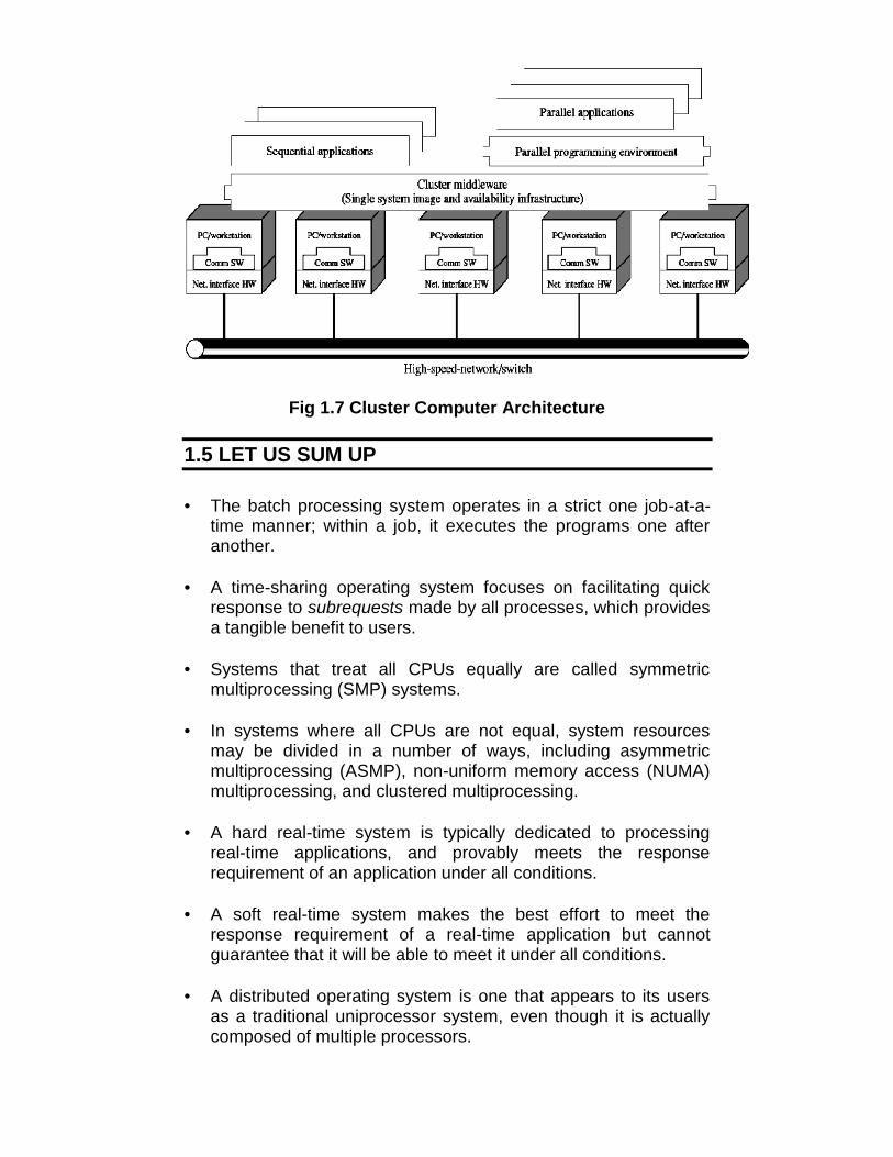
Fig 1.7 Cluster Computer Architecture
1.5 LET US SUM UP
• The batch processing system operates in a strict one job-at-a-time manner; within a job, it executes the programs one afteranother.
• A time-sharing operating system focuses on facilitating quickresponse to subrequests made by all processes, which providesa tangible benefit to users.
• Systems that treat all CPUs equally are called symmetricmultiprocessing (SMP) systems.
• In systems where all CPUs are not equal, system resourcesmay be divided in a number of ways, including asymmetricmultiprocessing (ASMP), non-uniform memory access (NUMA)multiprocessing, and clustered multiprocessing.
• A hard real-time system is typically dedicated to processingreal-time applications, and provably meets the responserequirement of an application under all conditions.
• A soft real-time system makes the best effort to meet theresponse requirement of a real-time application but cannotguarantee that it will be able to meet it under all conditions.
• A distributed operating system is one that appears to its usersas a traditional uniprocessor system, even though it is actuallycomposed of multiple processors.

• A desktop system is a personal computer (PC) system in a formintended for regular use at a single location, as opposed to amobile laptop or portable computer.
• One major difference between handhelds and PCs is that theformer do not have multigigabyte hard disks, which changes alot.
• Computer clusters emerged as a result of convergence of anumber of computing trends including the availability of low costmicroprocessors, high speed networks, and software for highperformance distributed computing.
1.6 UNIT END QUESTIONS
1. State the various classes of an operating system.2. What are the differences between symmetric and asymmetric
multiprocessing system?3. Briefly explain Real-Time Systems.4. Write a note on Clustered Systems.5. What are the key features of classes of operating systems?

2
TRANSFORMATION & EXECUTIONOF PROGRAMS
Unit Structure2.0 Objectives2.1 Introduction2.2 Translators and compilers2.3 Assemblers2.4 Interpreters
2.4.1 Compiled versus interpreted languages2.5 Linkers2.6 Let us sum up2.7 Unit end questions
2.0 OBJECTIVES
After going through this unit, you will be able to:• Study the transformation and execution of a program.
2.1 INTRODUCTION
An operating system is the code that carries out the systemcalls. Editors, compilers, assemblers, linkers, and commandinterpreters are not part of the operating system, even though theyare important and useful. But still we study them as they use manyOS resources.
2.2 TRANSLATORS AND COMPILERS
A translator is a program that takes a program written in oneprogramming language (the source language) as input andproduces a program in another language (the object or targetlanguage) as output.
If the source language is a high-level language such asFORTRAN (FORmula TRANslator), PL/I, or COBOL, and the objectlanguage is a low-level language such as an assembly language(machine language), then such a translator is called a compiler.
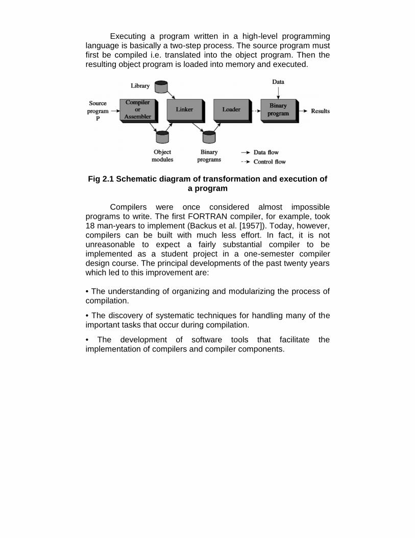
Executing a program written in a high-level programminglanguage is basically a two-step process. The source program mustfirst be compiled i.e. translated into the object program. Then theresulting object program is loaded into memory and executed.
Fig 2.1 Schematic diagram of transformation and execution ofa program
Compilers were once considered almost impossibleprograms to write. The first FORTRAN compiler, for example, took18 man-years to implement (Backus et al. [1957]). Today, however,compilers can be built with much less effort. In fact, it is notunreasonable to expect a fairly substantial compiler to beimplemented as a student project in a one-semester compilerdesign course. The principal developments of the past twenty yearswhich led to this improvement are:
• The understanding of organizing and modularizing the process ofcompilation.
• The discovery of systematic techniques for handling many of theimportant tasks that occur during compilation.
• The development of software tools that facilitate theimplementation of compilers and compiler components.
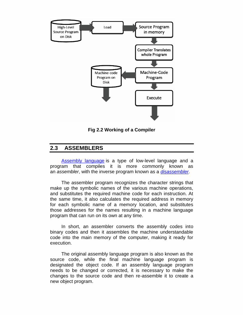
Fig 2.2 Working of a Compiler
2.3 ASSEMBLERS
Assembly language is a type of low-level language and aprogram that compiles it is more commonly known asan assembler, with the inverse program known as a disassembler.
The assembler program recognizes the character strings thatmake up the symbolic names of the various machine operations,and substitutes the required machine code for each instruction. Atthe same time, it also calculates the required address in memoryfor each symbolic name of a memory location, and substitutesthose addresses for the names resulting in a machine languageprogram that can run on its own at any time.
In short, an assembler converts the assembly codes intobinary codes and then it assembles the machine understandablecode into the main memory of the computer, making it ready forexecution.
The original assembly language program is also known as thesource code, while the final machine language program isdesignated the object code. If an assembly language programneeds to be changed or corrected, it is necessary to make thechanges to the source code and then re-assemble it to create anew object program.

Fig 2.3 Working of an Assembler
The functions of an assembler are given below:• It allows the programmer to use mnemonics while writing source
code programs, which are easier to read and follow.
• It allows the variables to be represented by symbolic names, notas memory locations.
• It translates mnemonic operations codes to machine code andcorresponding register addresses to system addresses.
• It checks the syntax of the assembly program and generatesdiagnostic messages on syntax errors.
• It assembles all the instructions in the main memory forexecution.
• In case of large assembly programs, it also provides linkingfacility among the subroutines.
• It facilitates the generation of output on required output medium.
2.4 INTERPRETERS
Unlike compilers, an interpreter translates a statement in aprogram and executes the statement immediately, beforetranslating the next source language statement. When an error isencountered in the program, the execution of the program is haltedand an error message is displayed. Similar to compilers, everyinterpreted language such as BASIC and LISP have their owninterpreters.
AssemblyProgram
Assembler
Machine LanguageProgram
Error Messages,Listings, etc.
(Source Code)
(Object Code)
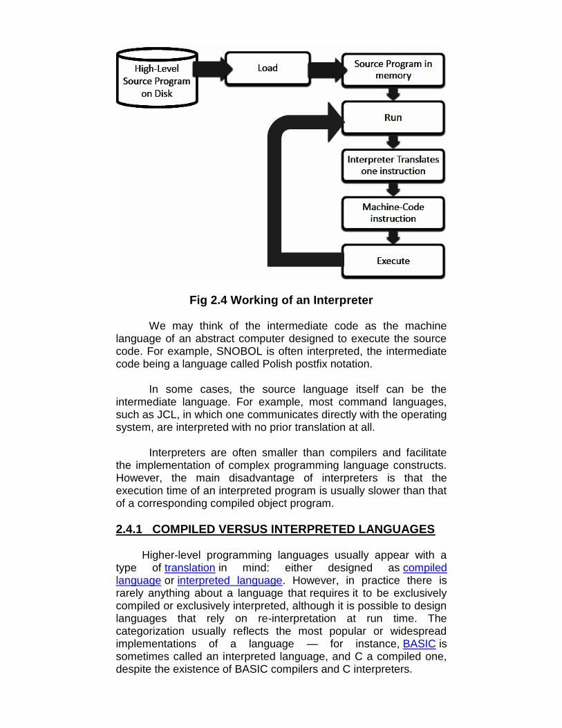
Fig 2.4 Working of an Interpreter
We may think of the intermediate code as the machinelanguage of an abstract computer designed to execute the sourcecode. For example, SNOBOL is often interpreted, the intermediatecode being a language called Polish postfix notation.
In some cases, the source language itself can be theintermediate language. For example, most command languages,such as JCL, in which one communicates directly with the operatingsystem, are interpreted with no prior translation at all.
Interpreters are often smaller than compilers and facilitatethe implementation of complex programming language constructs.However, the main disadvantage of interpreters is that theexecution time of an interpreted program is usually slower than thatof a corresponding compiled object program.
2.4.1 COMPILED VERSUS INTERPRETED LANGUAGES
Higher-level programming languages usually appear with atype of translation in mind: either designed as compiledlanguage or interpreted language. However, in practice there israrely anything about a language that requires it to be exclusivelycompiled or exclusively interpreted, although it is possible to designlanguages that rely on re-interpretation at run time. Thecategorization usually reflects the most popular or widespreadimplementations of a language — for instance, BASIC issometimes called an interpreted language, and C a compiled one,despite the existence of BASIC compilers and C interpreters.

Interpretation does not replace compilation completely. It onlyhides it from the user and makes it gradual. Even though aninterpreter can itself be interpreted, a directly executed program isneeded somewhere at the bottom of the stack (see machinelanguage). Modern trends toward just-in-timecompilation and bytecode interpretation at times blur the traditionalcategorizations of compilers and interpreters.
Some language specifications spell out that implementationsmust include a compilation facility; for example, Common Lisp.However, there is nothing inherent in the definition of Common Lispthat stops it from being interpreted. Other languages have featuresthat are very easy to implement in an interpreter, but make writing acompiler much harder; for example, APL, SNOBOL4, and manyscripting languages allow programs to construct arbitrary sourcecode at runtime with regular string operations, and then executethat code by passing it to a special evaluation function. Toimplement these features in a compiled language, programs mustusually be shipped with a runtime library that includes a version ofthe compiler itself.
2.5 LINKERS
An application usually consists of hundreds or thousands oflines of codes. The codes are divided into logical groups and storedin different modules so that the debugging and maintenance of thecodes becomes easier. Hence, for an application, it is alwaysadvisable to adhere to structural (modular) programming practices.When a program is broken into several modules, each module canbe modified and compiled independently. In such a case, thesemodules have to be linked together to create a completeapplication. This job is done by a tool known as linker.
A linker is a program that links several object modules andlibraries to form a single, coherent program (executable). Objectmodules are the machine code output from an assembler orcompiler and contain executable machine code and data, togetherwith information that allows the linker to combine the modulestogether to form a program.
Generally, all high-level languages use some in-built functionslike calculating square roots, finding logarithmic values, and so on.These functions are usually provided by the language itself, theprogrammer does not need to code them separately. During theprogram execution process, when a program invokes any in-builtfunction, the linker transfers the control to that program where thefunction is defined, by making the addresses of these functionsknown to the calling program.
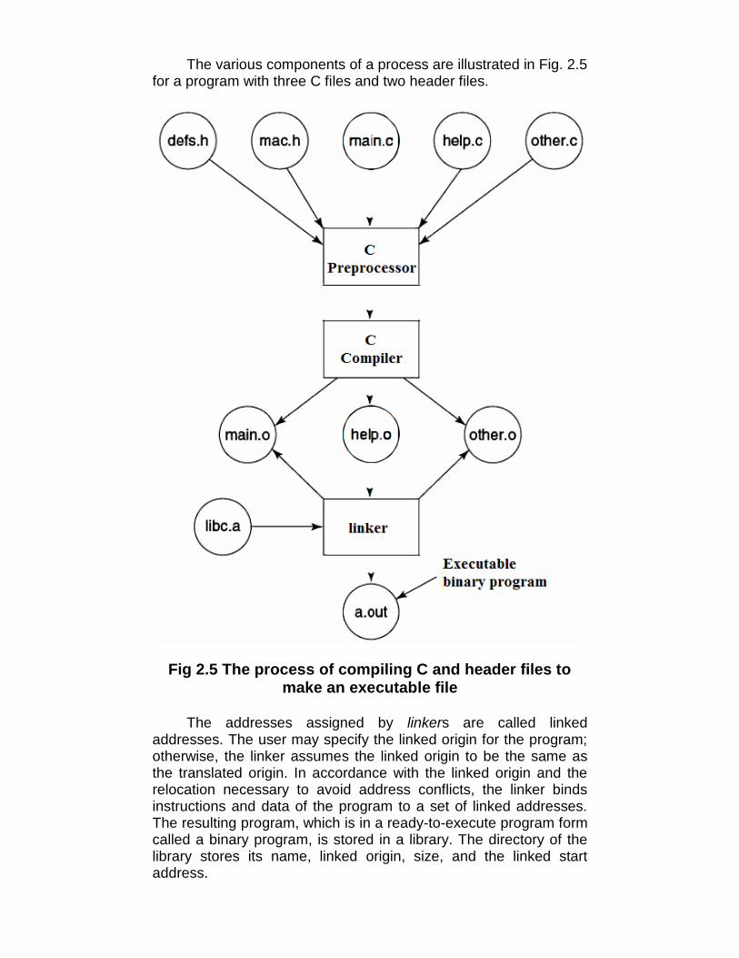
The various components of a process are illustrated in Fig. 2.5for a program with three C files and two header files.
Fig 2.5 The process of compiling C and header files tomake an executable file
The addresses assigned by linkers are called linkedaddresses. The user may specify the linked origin for the program;otherwise, the linker assumes the linked origin to be the same asthe translated origin. In accordance with the linked origin and therelocation necessary to avoid address conflicts, the linker bindsinstructions and data of the program to a set of linked addresses.The resulting program, which is in a ready-to-execute program formcalled a binary program, is stored in a library. The directory of thelibrary stores its name, linked origin, size, and the linked startaddress.

2.6 LET US SUM UP
• A translator is a program that takes a program written in oneprogramming language (the source language) as input andproduces a program in another language (the object or targetlanguage) as output.
• If the source language is a high-level language such asFORTRAN (FORmula TRANslator), PL/I, or COBOL, and theobject language is a low-level language such as an assemblylanguage (machine language), then such a translator is called acompiler.
• An assembler converts the assembly codes into binary codesand then it assembles the machine understandable code intothe main memory of the computer, making it ready forexecution.
• An interpreter translates a statement in a program and executesthe statement immediately, before translating the next sourcelanguage statement.
• A linker is a program that links several object modules andlibraries to form a single, coherent program (executable).
2.7 UNIT END QUESTIONS
1. Define :a. Translatorb. Assemblerc. Compilerd. Interpretere. Linker
2. State the functions of an assembler.3. Briefly explain the working of an interpreter.4. Distinguish between Compiled versus interpreted
Languages.5. What is a linker? Explain with the help of a diagram.

3
OS SERVICES, CALLS, INTERFACESAND PROGRAMS
Unit Structure3.0 Objectives3.1 Introduction3.2 Operating system services
3.2.1 Program execution3.2.2 I/O Operations3.2.3 File systems3.2.4 Communication3.2.5 Resource Allocation3.2.6 Accounting3.2.7 Error detection3.2.8 Protection and security
3.3 User Operating System Interface3.3.1 Command Interpreter3.3.2 Graphical user interface
3.4 System calls3.4.1 Types of system calls
3.4.1.1 Process control3.4.1.2 File management3.4.1.3 Device management3.4.1.4 Information maintenance3.4.1.5 Communications3.4.1.6 Protection
3.5 System programs3.5.1 File management3.5.2 Status information3.5.3 File modification3.5.4 Programming-language support3.5.5 Program loading and execution3.5.6 Communications
3.5.7 Application programs3.6 OS design and implementation3.7 Let us sum up3.8 Unit end questions
3.0 OBJECTIVES
After going through this unit, you will be able to:• Study different OS Services• Study different System Calls
3.1 INTRODUCTION
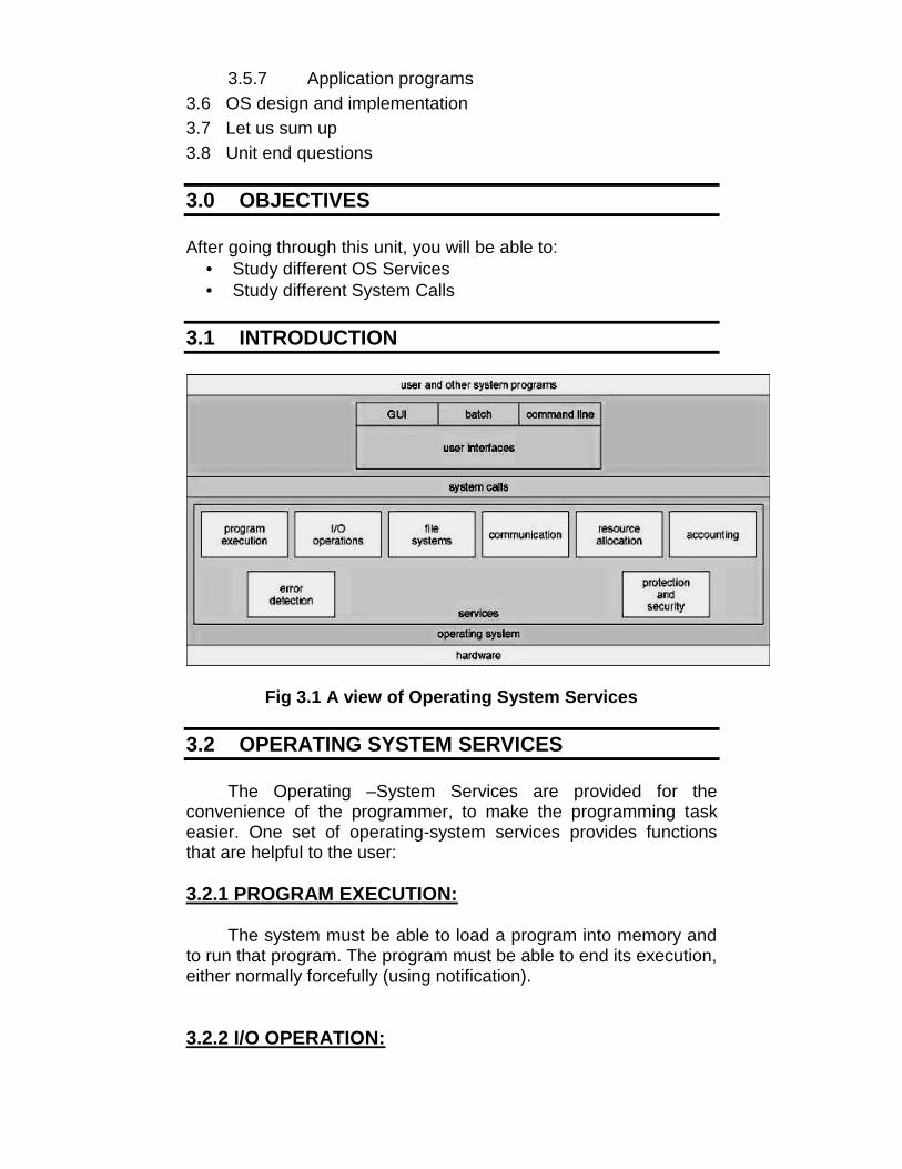
Fig 3.1 A view of Operating System Services
3.2 OPERATING SYSTEM SERVICES
The Operating –System Services are provided for theconvenience of the programmer, to make the programming taskeasier. One set of operating-system services provides functionsthat are helpful to the user:
3.2.1 PROGRAM EXECUTION:
The system must be able to load a program into memory andto run that program. The program must be able to end its execution,either normally forcefully (using notification).
3.2.2 I/O OPERATION:

I/O may involve a file or an I/O device. Special functions maybe desired (such as to rewind a tape drive, or to blank a CRTscreen). I/O devices are controlled by O.S.
3.2.3 FILE-SYSTEMS:
File system program reads, writes, creates and deletes filesby name.
3.2.4 COMMUNICATIONS:
In many circumstances, one process needs to exchangeinformation with another process. Communication may beimplemented via shared memory, or by the technique of messagepassing, in which packets of information are moved betweenprocesses by the O.S..
3.2.5 RESOURCE ALLOCATION:
When multiple users are logged on the system or multiple jobsare running at the same time, resources such as CPU cycles, mainmemory, and file storage etc. must be allocated to each of them.O.S. has CPU-scheduling routines that take into account the speedof the CPU, the jobs that must be executed, the number of registersavailable, and other factors. There are routines for tape drives,plotters, modems, and other peripheral devices.
3.2.6 ACCOUNTING:
To keep track of which user uses how many and what kinds ofcomputer resources. This record keeping may be used foraccounting (so that users can be billed) or simply for accumulatingusage statistics.
3.2.7 ERROR DETECTION:
Errors may occur in the CPU and memory hardware (such asa memory error or a power failure), in I/O devices (such as a parityerror on tape, a connection failure on a network, or lack of paper inthe printer), and in the user program (such as an arithmeticoverflow, an attempt to access an illegal memory location, or vastuse of CPU time). O.S should take an appropriate action to resolvethese errors.
3.2.8 PROTECTION AND SECURITY:
The owners of information stored in a multiuser or networkedcomputer system may want to control use of that information,concurrent processes should not interfere with each other
• Protection involves ensuring that all access to systemresources is controlled.
• Security of the system from outsiders requires userauthentication, extends to defending external I/O devices frominvalid access attempts.
• If a system is to be protected and secure, precautions must beinstituted throughout it. A chain is only as strong as its weakestlink.
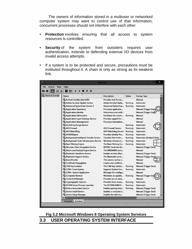
Fig 3.2 Microsoft Windows 8 Operating System Services3.3 USER OPERATING SYSTEM INTERFACE

Almost all operating systems have a user interface (UI)varying between Command-Line Interface (CLI) and Graphical UserInterface (GUI). These services differ from one operating system toanother but they have some common classes.
3.3.1 Command Interpreter:
It is the interface between user and OS. Some O.S. includesthe command interpreter in the kernel. Other O.S., such as MS-DOS and UNIX, treat the command interpreter as a specialprogram that is running when a job is initiated, or when a user firstlogs on (on time-sharing systems). This program is sometimescalled the control-card interpreter or the command-lineinterpreter, and is often known as the shell. Its function is simple:To get the next command statement and execute it. The commandstatements themselves deal with process creation andmanagement, I/O handling, secondary storage management, main-memory management, file –system access, protection, andnetworking. The MS-DOS and UNIX shells operate in this way.
3.3.2 Graphical User Interface (GUI):
With the development in chip designing technology,computer hardware became quicker and cheaper, which led to thebirth of GUI based operating system. These operating systemsprovide users with pictures rather than just characters to interactwith the machine.
A GUI:• Usually uses mouse, keyboard, and monitor.• Icons represent files, programs, actions, etc.• Various mouse buttons over objects in the interface cause
various actions (provide information, options, executefunction, open directory (known as a folder)
• Invented at Xerox PARC.
Many systems now include both CLI and GUI interfaces• Microsoft Windows is GUI with CLI “command” shell.• Apple Mac OS X as “LION” GUI interface with UNIX kernel
underneath and shells available.• Solaris is CLI with optional GUI interfaces (Java Desktop,
KDE).
3.4 SYSTEM CALLS
A system call is a request that a program makes to thekernel through a software interrupt.

System calls provide the interface between a process andthe operating system. These calls are generally available asassembly-language instructions.
Certain systems allow system calls to be made directly from ahigh-level language program, in which case the calls normallyresemble predefined function or subroutine calls.
Several languages-such as C, C++, and Perl-have beendefined to replace assembly language for system programming.These languages allow system calls to be made directly. E.g., UNIXsystem calls may be invoked directly from a C or C++ program.System calls for modern Microsoft Windows platforms are part ofthe Win32 application programmer interface (API), which isavailable for use by all the compilers written for Microsoft Windows.
Three most common APIs are Win32 API for Windows,POSIX API for POSIX-based systems (including virtually allversions of UNIX, Linux, and Mac OS X), and Java API for the Javavirtual machine (JVM).
Fig 3.3 Example of System Calls
Call Callnumber name Description
1 exit Terminate execution of thisprogram

3 read Read data from a file4 write Write data into a file5 open Open a file6 close Close a file7 waitpid Wait for a program’s execution to
terminate11 execve Execute a program12 chdir Change working directory14 chmod Change file permissions39 mkdir Make a new directory74 sethostname Set hostname of the computersystem78 gettimeofday Get time of day79 settimeofday Set time of day
Table 3.1 Some Linux System Calls
3.4.1 TYPES OF SYSTEM CALLS:
Traditionally, System Calls can be categorized in six groups,which are: Process Control, File Management, DeviceManagement, Information Maintenance, Communications andProtection.
3.4.1.1 PROCESS CONTROLEnd, abortLoad, executeCreate process, terminate processGet process attributes, set process attributesWait for timeWait event, signal eventAllocate and free memory
3.4.1.2 FILE MANAGEMENTCreate, delete fileOpen, closeRead, write, repositionGet file attributes, set file attributes
3.4.1.3 DEVICE MANAGEMENTRequest device, release deviceRead, write, repositionGet device attributes, set device attributesLogically attach or detach devices
3.4.1.4 INFORMATION MAINTENANCEGet time or date, set time or dateGet system data, set system dataGet process, file, or device attributesSet process, file, or device attributes

3.4.1.5 COMMUNICATIONSCreate, delete communication connectionSend, receive messagesTransfer status informationAttach or detach remote devices
3.4.1.6 PROTECTIONGet File Security, Set File SecurityGet Security Group, Set Security Group
Table 3.2 Examples of Windows and UNIX System Calls
3.5 SYSTEM PROGRAMS
System programs provide a convenient environment forprogram development and execution. System programs, alsoknown as system utilities, provide a convenient environment forprogram development and execution. Some of them are simplyuser interfaces to system calls; others are considerably morecomplex. They can be divided into these categories:
3.5.1 FILE MANAGEMENT:
These programs create, delete, copy, rename, print, dump,list, and generally manipulate files and directories.
.
3.5.2 STATUS INFORMATION:
Some programs simply ask the system for the date, time,amount of available memory or disk space, number of users, orsimilar status information. Others are more complex, providingdetailed performance, logging, and debugging information.Typically, these programs format and print the output to theterminal or other output devices or files or display it in a window ofthe GUI. Some systems also support a registry which is used tostore and retrieve configuration information.
3.5.3 FILE MODIFICATION:
Several text editors may be available to create and modify thecontent of files stored on disk or other storage devices. There mayalso be special commands to search contents of files or performtransformations of the text.
3.5.4 PROGRAMMING-LANGUAGE SUPPORT:
Compilers, assemblers, debuggers, and interpreters forcommon programming languages (such as C, C++, Java, VisualBasic, and PERL) are often provided to the user with the operatingsystem.
3.5.5 PROGRAM LOADING AND EXECUTION:
Once a program is assembled or compiled, it must be loadedinto memory to be executed. The system may provide absoluteloaders, re-locatable loaders, linkage editors, and overlay loaders.Debugging systems for either higher-level languages or machinelanguage are needed as well.
3.5.6 COMMUNICATIONS:
These programs provide the mechanism for creating virtualconnections among processes, users, and computer systems. Theyallow users to send messages to one another's screens, to browseWeb pages, to send electronic-mail messages, to log in remotely,or to transfer files from one machine to another.
3.5.7 APPLICATION PROGRAMS:

In addition to systems programs, most operating systemsare supplied with programs that are useful in solving commonproblems or performing common operations. Such applicationsinclude web browsers, word processors and text formatters,spreadsheets, database systems, compilers, plotting and statisticalanalysis packages, and games.
3.6 OS DESIGN AND IMPLEMENTATION
We face problems in designing and implementing anoperating system. There are few approaches that have provedsuccessful.
Design GoalsSpecifying and designing an operating system is a highly
creative task. The first problem in designing a system is to definegoals and specifications. At the highest level, the design of thesystem will be affected by the choice of hardware and the type ofsystem: batch, time shared, single user, multiuser, distributed, realtime, or general purpose. Beyond this highest design level, therequirements may be much harder to specify. The requirementscan, however, be divided into two basic groups: user goals andsystem goals.
Users desire certain properties in a system. The systemshould be convenient to use, easy to learn and to use, reliable,safe, and fast. These specifications are not particularly useful in thesystem design, since there is no general agreement to achievethem.
A similar set of requirements can be defined by people whomust design, create, maintain, and operate the system. The systemshould be easy to design, implement, and maintain; and it shouldbe flexible, reliable, error free, and efficient. Again, theserequirements are vague and may be interpreted in various ways.There is, in short, no unique solution to the problem of defining therequirements for an operating system. The wide range of systemsin existence shows that different requirements can result in a largevariety of solutions for different environments. For example, therequirements for VxWorks, a real-time operating system forembedded systems, must have been substantially different fromthose for MVS, a large multiuser, multi-access operating system forIBM mainframes.
ImplementationOnce an operating system is designed, it must be
implemented. Traditionally, operating systems have been written inassembly language. Now, however, they are most commonlywritten in higher-level languages such as C or C++. The firstsystem that was not written in assembly language was probably the
Master Control Program (MCP) for Burroughs computers and it waswritten in a variant of ALGOL. MULTICS, developed at MIT, waswritten mainly in PL/1. The Linux and Windows XP operatingsystems are written mostly in C, although there are some smallsections of assembly code for device drivers and for saving andrestoring the state of registers.
The advantages of using a higher-level language, or at least asystems implementation language, for implementing operatingsystems are the same as those accrued when the language is usedfor application programs: the code can be written faster, is morecompact, and is easier to understand and debug.
In addition, improvements in compiler technology will improvethe generated code for the entire operating system by simplerecompilation. Finally, an operating system is far easier to port-tomove to some other hardware-if it is written in a higher-levellanguage. For example, MS-DOS was written in Intel 8088assembly language. Consequently, it runs natively only on the IntelX86 family of CPUs. (Although MS-DOS runs natively only on IntelX86, emulators of the X86 instruction set allow the operatingsystem to run non-natively slower, with more resource use-on otherCPUs are programs that duplicate the functionality of one systemwith another system.) The Linux operating system, in contrast, iswritten mostly in C and is available natively on a number of differentCPUs, including Intel X86, Sun SPARC, and IBMPowerPC.
The only possible disadvantages of implementing anoperating system in a higher-level language are reduced speed andincreased storage requirements. Although an expert assembly-language programmer can produce efficient small routines, forlarge programs a modern compiler can perform complex analysisand apply sophisticated optimizations that produce excellent code.Modern processors have deep pipelining and multiple functionalunits that can handle the details of complex dependencies muchmore easily than can the human mind. Major performanceimprovements in operating systems are more likely to be the resultof better data structures and algorithms than of excellent assembly-language code.
In addition, although operating systems are large, only a smallamount of the code is critical to high performance; the memorymanager and the CPU scheduler are probably the most criticalroutines. After the system is written and is working correctly,bottleneck routines can be identified and can be replaced withassembly-language equivalents.

3.7 LET US SUM UP
• Almost all operating systems have a user interface (UI) varyingbetween Command-Line Interface (CLI) and Graphical UserInterface (GUI).
• Microsoft Windows is GUI with CLI “command” shell.
• Apple Mac OS X as “LION” GUI interface with UNIX kernelunderneath and shells available.
• Solaris is CLI with optional GUI interfaces (Java Desktop, KDE).
• A system call is a request that a program makes to the kernelthrough a software interrupt.
• System Calls can be categorized in six groups, which are:Process Control, File Management, Device Management,Information Maintenance, Communications and Protection.
• System programs provide a convenient environment forprogram development and execution.
• The first system that was not written in assembly language wasprobably the Master Control Program (MCP) for Burroughscomputers and it was written in a variant of ALGOL.
• Modern processors have deep pipelining and multiple functionalunits that can handle the details of complex dependencies muchmore easily than can the human mind.
3.8 UNIT END QUESTIONS
1. State different operating system services.2. Describe different system calls.3. Describe Command interpreter in brief.4. Write a short note on Design and implementation of an
Operating System.

4OPERATING SYSTEM STRUCTURES
Unit Structure4.0 Objectives4.1 Introduction4.2 Operating system structures
4.2.1 Simple structure4.2.2 Layered approach4.2.3 Microkernel approach4.2.4 Modules
4.3 Operating system generation4.4 System boot4.5 Let us sum up4.6 Unit end questions
4.0 OBJECTIVES
After going through this unit, you will be able to:• Study how components of OS are interconnected and melded
into a kernel.• Study different Virtual Machines• Distinguish between different levels of Computer
4.1 INTRODUCTION
For efficient performance and implementation an OS shouldbe partitioned into separate subsystems, each with carefullydefined tasks, inputs, outputs, and performance characteristics.These subsystems can then be arranged in various architecturalconfigurations discussed in brief in this unit.
4.2 OPERATING SYSTEM STRUCTURES
A modern operating system must be engineered carefully if itis to function properly and be modified easily. A common approachis to partition the task into small components rather than have onemonolithic system. Each of these modules should be a well-definedportion of the system, with carefully defined inputs, outputs, andfunctions.

4.2.1 SIMPLE STRUCTURE:
Microsoft Disk Operating System [MS-DOS]: In MS-DOS,application programs are able to access the basic I/O routines towrite directly to the display and disk drives. Such freedom leavesMS-DOS vulnerable to errant (or malicious) programs, causingentire system to crash when user programs fail.
Because the Intel 8088 for which it was written provides nodual mode and no hardware protection, the designers of MS-DOShad no choice but to leave the base hardware accessible. Anotherexample of limited structuring is the original UNIX operatingsystem. It consists of two separable parts, the kernel and thesystem programs. The kernel is further separated into a series ofinterfaces and device drivers. We can view the traditional UNIXoperating system as being layered. Everything below the system-call interface and above the physical hardware is the kernel.
The kernel provides the file system, CPU scheduling, memorymanagement, and other operating system functions through systemcalls. Taken in sum that is an enormous amount of functionality tobe combined into one level. This monolithic structure was difficult toimplement and maintain.
4.2.2 LAYERED APPROACH:
In layered approach, the operating system is broken into anumber of layers (levels). The bottom layer (layer 0) is thehardware, the highest (layer N) is the user interface. An operatingsystem layer is an implementation of an abstract object made up ofdata and the operations that can manipulate those data. A typicaloperating system layer say, layer M consists of data structures anda set of routines that can be invoked by higher level layers. LayerM, in turn, can invoke operations on lower level layers.
The main advantage of the layered approach is simplicity ofconstruction and debugging. The layers are selected so that eachuses functions (operations) and services of only lower-level layers.This approach simplifies debugging and system verification. Thefirst layer can be debugged without any concern for the rest of thesystem, because, by definition, it uses only the basic hardware toimplement its functions.
Once the first layer is debugged, its correct functioning can beassumed while the second layer is debugged, and so on. If an erroris found during the debugging of a particular layer, the error mustbe on that layer, because the layers below it are already debugged.Each layer is implemented with only those operations provided bylower level layers. Each layer hides the existence of certain datastructures, operations, and hardware from higher-level layers.
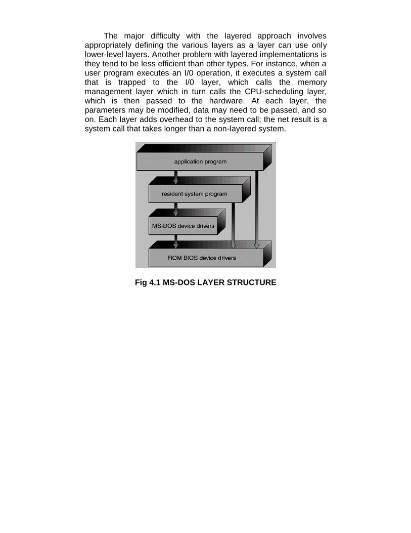
The major difficulty with the layered approach involvesappropriately defining the various layers as a layer can use onlylower-level layers. Another problem with layered implementations isthey tend to be less efficient than other types. For instance, when auser program executes an I/0 operation, it executes a system callthat is trapped to the I/0 layer, which calls the memorymanagement layer which in turn calls the CPU-scheduling layer,which is then passed to the hardware. At each layer, theparameters may be modified, data may need to be passed, and soon. Each layer adds overhead to the system call; the net result is asystem call that takes longer than a non-layered system.
Fig 4.1 MS-DOS LAYER STRUCTURE
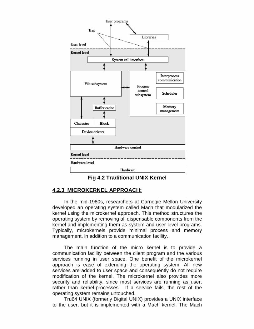
Fig 4.2 Traditional UNIX Kernel
4.2.3 MICROKERNEL APPROACH:
In the mid-1980s, researchers at Carnegie Mellon Universitydeveloped an operating system called Mach that modularized thekernel using the microkernel approach. This method structures theoperating system by removing all dispensable components from thekernel and implementing them as system and user level programs.Typically, microkernels provide minimal process and memorymanagement, in addition to a communication facility.
The main function of the micro kernel is to provide acommunication facility between the client program and the variousservices running in user space. One benefit of the microkernelapproach is ease of extending the operating system. All newservices are added to user space and consequently do not requiremodification of the kernel. The microkernel also provides moresecurity and reliability, since most services are running as user,rather than kernel-processes. If a service fails, the rest of theoperating system remains untouched.
Tru64 UNIX (formerly Digital UNIX) provides a UNIX interfaceto the user, but it is implemented with a Mach kernel. The Mach

kernel maps UNIX system calls into messages to the appropriateuser-level services. The Mac OS X kernel (also known as Darwin)is also based on the Mach micro kernel. Another example is QNX,a real-time operating system. The QNX microkernel providesservices for message passing and process scheduling. It alsohandles low-level network communication and hardware interrupts.All other services in QNX are provided by standard processes thatrun outside the kernel in user mode.
Microkernels can suffer from decreased performance due toincreased system function overhead.
Fig 4.3 Modern UNIX Kernel
4.2.4 MODULES:
The current methodology for operating-system design involvesusing object-oriented programming techniques to create a modularkernel. Here, the kernel has a set of core components and links inadditional services either during boot time or during run time. Sucha strategy uses dynamically loadable modules. Most current UNIX-like systems, and Microsoft Windows, support loadable kernelmodules, although they might use a different name for them, suchas kernel loadable module (kld) in FreeBSD and kernelextension (kext) in OS X. They are also known as Kernel LoadableModules (or KLM), and simply as Kernel Modules (KMOD). Forexample, the Solaris operating system structure, shown in figure

below, is organized around a core kernel with seven types ofloadable kernel modules.
Fig 4.4 Solaris Loadable Modules
Such a design allows the kernel to provide core services yetalso allows certain features to be implemented dynamically. Forexample, device and bus drivers for specific hardware can beadded to the kernel, and support for different file systems can beadded as loadable modules. The overall result resembles a layeredsystem where each kernel section has defined, protectedinterfaces; but it is more flexible than a layered system where anymodule can call any other module.
Furthermore, the approach is like the microkernel approachwhere the primary module has only core functions and knowledgeof how to load and communicate with other modules; but it is moreefficient, because modules do not need to invoke message passingin order to communicate. The Apple Mac OS X operating systemuses a hybrid structure. It is a layered system in which one layerconsists of the Mach microkernel.
The top layers include application environments and a set ofservices providing a graphical interface to applications. Below these
Device andbus drivers
Miscellane-ous
STREAMSModules
ExecutableFormats
LoadableSystemCalls
File systems
SchedulingClasses
Core SolarisKernel

layers is the kernel environment, which consists primarily of theMach microkernel and the BSD kernel. Mach provides memorymanagement; support for remote procedure calls (RPCs) and inter-process communication (IPC) facilities, including message passing;and thread scheduling.
The BSD component provides a BSD command line interface,support for networking and file systems, and an implementation ofPOSIX APIs, including Pthreads. In addition to Mach and BSD, thekernel environment provides an i/o kit for development of devicedrivers and dynamically loadable modules (which Mac OS X refersto as kernel extensions). Applications and common services canmake use of either the Mach or BSD facilities directly.
4.3 OPERATING SYSTEM GENERATION
Operating Systems may be designed and built for a specifichardware configuration at a specific site, but more commonly theyare designed with a number of variable parameters andcomponents, which are then configured for a particular operatingenvironment.
Systems sometime need to be re-configured after the initialinstallation, to add additional resources, capabilities, or to tuneperformance, logging, or security.
Information that is needed to configure an OS include:
• What CPU(s) are installed on the system, and what optionalcharacteristics does each have?
• How much RAM is installed? (This may be determinedautomatically, either at install or boot time.)
• What devices are present? The OS needs to determine whichdevice drivers to include, as well as some device-specificcharacteristics and parameters.
• What OS options are desired, and what values to set forparticular OS parameters. The latter may include the size of theopen file table, the number of buffers to use, process scheduling(priority) parameters, disk scheduling algorithms, number ofslots in the process table, etc.
At one extreme the OS source code can be edited, re-compiled,and linked into a new kernel.
More commonly configuration tables determine whichmodules to link into the new kernel, and what values to set forsome key important parameters. This approach may require theconfiguration of complicated make files, which can be done eitherautomatically or through interactive configuration programs; then

make is used to actually generate the new kernel specified by thenew parameters.
At the other extreme a system configuration may be entirelydefined by table data, in which case the "rebuilding" of the systemmerely requires editing data tables.
Once a system has been regenerated, it is usually required toreboot the system to activate the new kernel. Because there arepossibilities for errors, most systems provide some mechanism forbooting to older or alternate kernels.
4.4 SYSTEM BOOT
The general approach when most computers boot up goessomething like this:
When the system powers up, an interrupt is generated whichloads a memory address into the program counter, and the systembegins executing instructions found at that address. This addresspoints to the "bootstrap" program located in ROM chips (or EPROMchips) on the motherboard.
The ROM bootstrap program first runs hardware checks,determining what physical resources are present and doing power-on self tests (POST) of all HW for which this is applicable. Somedevices, such as controller cards may have their own on-boarddiagnostics, which are called by the ROM bootstrap program.
The user generally has the option of pressing a special keyduring the POST process, which will launch the ROM BIOSconfiguration utility if pressed. This utility allows the user to specifyand configure certain hardware parameters as where to look for anOS and whether or not to restrict access to the utility with apassword.
Some hardware may also provide access to additionalconfiguration setup programs, such as for a RAID disk controller orsome special graphics or networking cards.
Assuming the utility has not been invoked, the bootstrapprogram then looks for a non-volatile storage device containing anOS. Depending on configuration, it may look for a floppy drive, CDROM drive, or primary or secondary hard drives, in the orderspecified by the HW configuration utility.
Assuming it goes to a hard drive, it will find the first sector onthe hard drive and load up the fdisk table, which containsinformation about how the physical hard drive is divided up into

logical partitions, where each partition starts and ends, and whichpartition is the "active" partition used for booting the system.
There is also a very small amount of system code in theportion of the first disk block not occupied by the fdisk table. Thisbootstrap code is the first step that is not built into the hardware, i.e.the first part which might be in any way OS-specific. Generally thiscode knows just enough to access the hard drive, and to load andexecute a (slightly) larger boot program.
For a single-boot system, the boot program loaded off of thehard disk will then proceed to locate the kernel on the hard drive,load the kernel into memory, and then transfer control over to thekernel. There may be some opportunity to specify a particularkernel to be loaded at this stage, which may be useful if a newkernel has just been generated and doesn't work, or if the systemhas multiple kernels available with different configurations fordifferent purposes. (Some systems may boot differentconfigurations automatically, depending on what hardware hasbeen found in earlier steps. )
For dual-boot or multiple-boot systems, the boot program willgive the user an opportunity to specify a particular OS to load, witha default choice if the user does not pick a particular OS within agiven time frame. The boot program then finds the boot loader forthe chosen single-boot OS, and runs that program as described inthe previous bullet point.
Once the kernel is running, it may give the user theopportunity to enter into single-user mode, also known asmaintenance mode. This mode launches very few if any systemservices, and does not enable any logins other than the primary login on the console. This mode is used primarily for systemmaintenance and diagnostics.
When the system enters full multi-user multi-tasking mode, itexamines configuration files to determine which system servicesare to be started, and launches each of them in turn. It then spawnslogin programs ( gettys ) on each of the login devices which havebeen configured to enable user logins.
(The getty program initializes terminal I/O, issues the loginprompt, accepts login names and passwords, and authenticates theuser. If the user's password is authenticated, then the getty looks insystem files to determine what shell is assigned to the user, andthen "execs" (becomes) the user's shell. The shell program will lookin system and user configuration files to initialize itself, and thenissue prompts for user commands. Whenever the shell dies, eitherthrough logout or other means, then the system will issue a newgetty for that terminal device.)
4.5 LET US SUM UP
• In MS-DOS, application programs are able to access the basicI/O routines to write directly to the display and disk drives.
• In layered approach, the operating system is broken into anumber of layers (levels). The bottom layer (layer 0) is thehardware, the highest (layer N) is the user interface.
• The main advantage of the layered approach is simplicity ofconstruction and debugging
• In the mid-1980s, researchers at Carnegie Mellon Universitydeveloped an operating system called Mach that modularizedthe kernel using the microkernel approach
• The main function of the micro kernel is to provide acommunication facility between the client program and thevarious services running in user space
• Tru64 UNIX (formerly Digital UNIX) provides a UNIX interface tothe user, but it is implemented with a Mach kernel
• Most current UNIX-like systems, and Microsoft Windows,support loadable kernel modules, although they might use adifferent name for them, such as kernel loadable module (kld)in FreeBSD and kernel extension (kext) in OS X
• In addition to Mach and BSD, the kernel environment providesan i/o kit for development of device drivers and dynamicallyloadable modules (which Mac OS X refers to as kernelextensions).
• Once a system has been regenerated, it is usually required toreboot the system to activate the new kernel
• For dual-boot or multiple-boot systems, the boot program willgive the user an opportunity to specify a particular OS to load,with a default choice if the user does not pick a particular OSwithin a given time frame.
4.6 UNIT END QUESTIONS
5. What are the differences between layered approach andmicrokernel approach?
6. What information is needed to configure an OS?
7. What do you mean by System Boot?
8. Define:a. Kernel loadable modulesb. Maintenance mode

5
VIRTUAL MACHINES
Unit Structure5.0 Objectives5.1 Introduction5.2 Virtual Machines
5.2.1 History5.2.2 Benefits5.2.3 Simulation5.2.4 Para-virtualization5.2.5 Implementation5.2.6 Examples
5.2.6.1 VMware 5.2.6.2 The java virtual machine5.2.6.3 The .net framework
5.3 Let us sum up5.4 Unit end questions
5.0 OBJECTIVES
After going through this unit, you will be able to:• Study evolution of Virtual Machines.• Distinguish between different Virtual Machines.
5.1 INTRODUCTION
The fundamental idea behind a virtual machine is to abstractthe hardware of a single computer (the CPU, memory, disk drives,network interface cards, and so forth) into several differentexecution environments, thereby creating the illusion that eachseparate execution environment is running its own privatecomputer. By using CPU scheduling and virtual-memorytechniques, an operating system can create the illusion that aprocess has its own processor with its own (virtual) memory.
5.2 VIRTUAL MACHINES
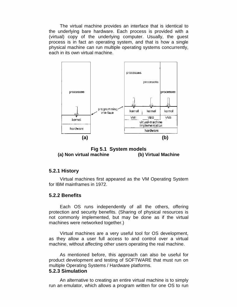
The virtual machine provides an interface that is identical tothe underlying bare hardware. Each process is provided with a(virtual) copy of the underlying computer. Usually, the guestprocess is in fact an operating system, and that is how a singlephysical machine can run multiple operating systems concurrently,each in its own virtual machine.
(a) (b)
Fig 5.1 System models(a) Non virtual machine (b) Virtual Machine
5.2.1 HistoryVirtual machines first appeared as the VM Operating System
for IBM mainframes in 1972.
5.2.2 Benefits
Each OS runs independently of all the others, offeringprotection and security benefits. (Sharing of physical resources isnot commonly implemented, but may be done as if the virtualmachines were networked together.)
Virtual machines are a very useful tool for OS development,as they allow a user full access to and control over a virtualmachine, without affecting other users operating the real machine.
As mentioned before, this approach can also be useful forproduct development and testing of SOFTWARE that must run onmultiple Operating Systems / Hardware platforms.5.2.3 Simulation
An alternative to creating an entire virtual machine is to simplyrun an emulator, which allows a program written for one OS to run

on a different OS. For example, a UNIX machine may run a DOSemulator in order to run DOS programs, or vice-versa. Emulatorstend to run considerably slower than the native OS, and are alsogenerally less than perfect.
5.2.4 Para-virtualization
Para-virtualization is another variation on the theme, in whichan environment is provided for the guest program that is similarto its native OS, without trying to completely mimic it.
Guest programs must also be modified to run on the para-virtual OS.Solaris 10 uses a zone system, in which the low-level hardware isnot virtualized, but the OS and its devices (device drivers) are.
Within a zone, processes have the view of an isolated system,in which only the processes and resources within that zone areseen to exist. Figure 5.2 shows a Solaris system with the normal"global" operating space as well as two additional zones running ona small virtualization layer.
Fig 5.2 Solaris 10 with two containers5.2.5 Implementation
Implementation may be challenging, partially due to theconsequences of user versus kernel mode. Each of the

simultaneously running kernels needs to operate in kernel mode atsome point, but the virtual machine actually runs in user mode.
So the kernel mode has to be simulated for each of the loadedOperating Systems, and kernel system calls passed through thevirtual machine into a true kernel mode for eventual hardwareaccess.
The virtual machines may run slower, due to the increasedlevels of code between applications and the hardware, or they mayrun faster, due to the benefits of caching. (And virtual devices mayalso be faster than real devices, such as RAM disks which arefaster than physical disks).
5.2.6 Examples5.2.6.1 VMware
VMware Workstation runs as an application on a hostoperating system such as Windows or Linux and allows this hostsystem to concurrently run several different guest operatingsystems as independent virtual machines. In this scenario, Linux isrunning as the host operating system; and FreeBSD, Windows NT,and Windows XP are running as guest operating systems. Thevirtualization layer is the heart of VMware, as it abstracts thephysical hardware into isolated virtual machines running as guestoperating systems.
Each virtual machine has its own virtual CPU, memory, diskdrives, network interfaces, and so forth. The physical disk the guestowns and manages is a file within the file system of the hostoperating system. To create an identical guest instance, we cansimply copy the file. Copying the file to another location protects theguest instance against a disaster at the original site. Moving the fileto another location moves the guest system. These scenarios showhow virtualization can improve the efficiency of systemadministration as well as system resource use.
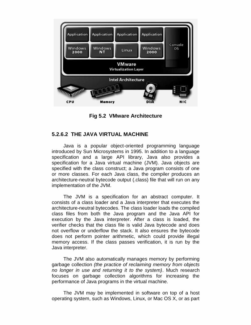
Fig 5.2 VMware Architecture
5.2.6.2 THE JAVA VIRTUAL MACHINE
Java is a popular object-oriented programming languageintroduced by Sun Microsystems in 1995. In addition to a languagespecification and a large API library, Java also provides aspecification for a Java virtual machine (JVM). Java objects arespecified with the class construct; a Java program consists of oneor more classes. For each Java class, the compiler produces anarchitecture-neutral bytecode output (.class) file that will run on anyimplementation of the JVM.
The JVM is a specification for an abstract computer. Itconsists of a class loader and a Java interpreter that executes thearchitecture-neutral bytecodes. The class loader loads the compiledclass files from both the Java program and the Java API forexecution by the Java interpreter. After a class is loaded, theverifier checks that the class file is valid Java bytecode and doesnot overflow or underflow the stack. It also ensures the bytecodedoes not perform pointer arithmetic, which could provide illegalmemory access. If the class passes verification, it is run by theJava interpreter.
The JVM also automatically manages memory by performinggarbage collection (the practice of reclaiming memory from objectsno longer in use and returning it to the system). Much researchfocuses on garbage collection algorithms for increasing theperformance of Java programs in the virtual machine.
The JVM may be implemented in software on top of a hostoperating system, such as Windows, Linux, or Mac OS X, or as part
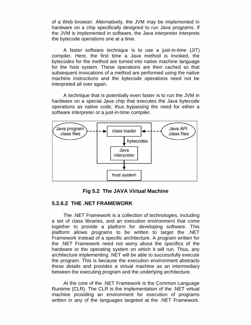
of a Web browser. Alternatively, the JVM may be implemented inhardware on a chip specifically designed to run Java programs. Ifthe JVM is implemented in software, the Java interpreter interpretsthe bytecode operations one at a time.
A faster software technique is to use a just-in-time (JIT)compiler. Here, the first time a Java method is invoked, thebytecodes for the method are turned into native machine languagefor the host system. These operations are then cached so thatsubsequent invocations of a method are performed using the nativemachine instructions and the bytecode operations need not beinterpreted all over again.
A technique that is potentially even faster is to run the JVM inhardware on a special Java chip that executes the Java bytecodeoperations as native code, thus bypassing the need for either asoftware interpreter or a just-in-time compiler.
Fig 5.2 The JAVA Virtual Machine
5.2.6.2 THE .NET FRAMEWORK
The .NET Framework is a collection of technologies, includinga set of class libraries, and an execution environment that cometogether to provide a platform for developing software. Thisplatform allows programs to be written to target the .NETFramework instead of a specific architecture. A program written forthe .NET Framework need not worry about the specifics of thehardware or the operating system on which it will run. Thus, anyarchitecture implementing .NET will be able to successfully executethe program. This is because the execution environment abstractsthese details and provides a virtual machine as an intermediarybetween the executing program and the underlying architecture.
At the core of the .NET Framework is the Common LanguageRuntime (CLR). The CLR is the implementation of the .NET virtualmachine providing an environment for execution of programswritten in any of the languages targeted at the .NET Framework.

Programs written in languages such as C# and VB.NET arecompiled into an intermediate, architecture-independent languagecalled Microsoft Intermediate Language (MS-IL). These compiledfiles, called assemblies, include MS-IL instructions and metadata.They have file extensions of either .EXE or .DLL. Upon execution ofa program, the CLR loads assemblies into what is known as theApplication Domain. As instructions are requested by the executingprogram, the CLR converts the MS-IL instructions inside theassemblies into native code that is specific to the underlyingarchitecture using just-in-time compilation.
Once instructions have been converted to native code, theyare kept and will continue to run as native code for the CPU. Thearchitecture of the CLR for the .NET framework is shown inFigure 5.3.
Fig 5.3 Architecture of the CLR for the .NET Framework
5.3 LET US SUM UP
• Virtual machines first appeared as the VM Operating System forIBM mainframes in 1972.
• Para-virtualization is another variation on the theme, in which anenvironment is provided for the guest program that is similarto its native OS, without trying to completely mimic it.
• Solaris 10 uses a zone system, in which the low-level hardwareis not virtualized, but the OS and its devices (device drivers)are.
• The virtualization layer is the heart of VMware, as it abstractsthe physical hardware into isolated virtual machines running asguest operating systems.
• It consists of a class loader and a Java interpreter that executesthe architecture-neutral bytecodes.
• A faster software technique is to use a just-in-time (JIT)compiler. Here, the first time a Java method is invoked, thebytecodes for the method are turned into native machinelanguage for the host system.
• The .NET Framework is a collection of technologies, including aset of class libraries, and an execution environment that cometogether to provide a platform for developing software.
5.4 UNIT END QUESTIONS
9. Write a short note on Virtual Machines.
10.Define : (a) Para-virtualization (b) JVM
11.Describe the architecture of :(a) The JAVA Virtual Machine(b) CLR for the .NET Framework

6
PROCESS
Unit Structure6.0 Objectives6.1 Introduction6.2 Process concepts
6.2.1 Process states6.2.2 Process control block6.2.3 Threads
6.3 Process scheduling6.4 Scheduling criteria6.5 Let us sum up6.6 Unit end questions
6.0 OBJECTIVES
After reading this unit you will be able to:• Define a process• Study various process scheduling criteria
6.1 INTRODUCTION
The design of an operating system must be done in such away that all requirement should be fulfilled.
• The operating system must interleave the execution of multipleprocesses, to maximize processor utilization while providingreasonable response time.
• The operating system must allocate resources to processes inconformance with a specific policy.
• The operating system may be required to support interprocesscommunication and user creation of processes.
6.2 PROCESS CONCEPTS

Process can be defined as:• A program in execution.• An instance of a program running on a computer.• The entity that can be assigned to and executed on a processor.• A unit of activity characterized by the execution of a sequence
of instructions, a current state, and an associated set of systemresources
A process is an entity that consists of a number of elements.Two essential elements of a process are program code, and a setof data associated with that code.
A process is more than the program code, which is sometimesknown as the text section. It also includes the current activity, asrepresented by the value of the program counter and the contentsof the processor's registers. A process generally also includes theprocess stack, which contains temporary data (such as functionparameters, return addresses, and local variables), and a datasection, which contains global variables. A process may alsoinclude a heap, which is memory that is dynamically allocatedduring process run time.
Fig 6.1 Process in Memory
6.2.1 PROCESS STATES
As a process executes, it changes state• New: The process is being created• Running: Instructions are being executed• Waiting: The process is waiting for some event to occur• Ready: The process is waiting to be assigned to a
processor• Terminated: The process has finished execution

Fig 6.2 Block diagram of Process States
6.2.2 PROCESS CONTROL BLOCK
IdentifierState
PriorityProgram CounterMemory Pointers
Context dataI/O status information
Accountinginformation
•••
Fig 6.3 Process Control Block (PCB)
Each process is described in the operating system bya process control block (PCB) also called a task control block. APCB contains much of the information related to a specific process,including these:
Process state:The state may be new, ready running, waiting, halted, and so on.
Program counter:The counter indicates the address of the next instruction to beexecuted for this process.
CPU registers:The registers vary in number and type, depending on the computerarchitecture. They include accumulators, index registers, stackpointers, and general-purpose registers, plus any condition-codeinformation. Along with the program counter, this state informationmust be saved when an interrupt occurs, to allow the process to becontinued correctly afterward.
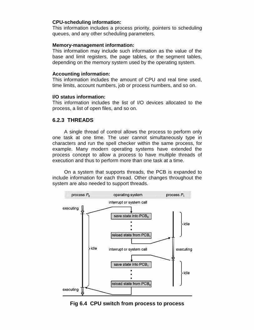
CPU-scheduling information:This information includes a process priority, pointers to schedulingqueues, and any other scheduling parameters.
Memory-management information:This information may include such information as the value of thebase and limit registers, the page tables, or the segment tables,depending on the memory system used by the operating system.
Accounting information:This information includes the amount of CPU and real time used,time limits, account numbers, job or process numbers, and so on.
I/O status information:This information includes the list of I/O devices allocated to theprocess, a list of open files, and so on.
6.2.3 THREADS
A single thread of control allows the process to perform onlyone task at one time. The user cannot simultaneously type incharacters and run the spell checker within the same process, forexample. Many modern operating systems have extended theprocess concept to allow a process to have multiple threads ofexecution and thus to perform more than one task at a time.
On a system that supports threads, the PCB is expanded toinclude information for each thread. Other changes throughout thesystem are also needed to support threads.
Fig 6.4 CPU switch from process to process

6.3 PROCESS SCHEDULING
When a computer is multiprogrammed, it frequently hasmultiple processes or threads competing for the CPU at the sametime. This situation occurs whenever two or more of them aresimultaneously in the ready state. If only one CPU is available, achoice has to be made which process to run next. The part of theoperating system that makes the choice is called the scheduler,and the algorithm it uses is called the scheduling algorithm.
6.4 SCHEDULING CRITERIA
In order to design a scheduling algorithm, it is necessary tohave some idea of what a good algorithm should do. Some goalsdepend on the environment (batch, interactive, or real time), butthere are also some that are desirable in all cases. Some goals(scheduling criteria) are listed below.
All systemsFairness - giving each process a fair share of the CPUPolicy enforcement - seeing that stated policy is carried outBalance - keeping all parts of the system busy
Batch systemsThroughput - maximize jobs per hourTurnaround time - minimize time between submission andterminationCPU utilization - keep the CPU busy all the time
Interactive systemsResponse time - respond to requests quicklyProportionality - meet users' expectations
Real-time systemsMeeting deadlines - avoid losing dataPredictability - avoid quality degradation in multimedia systems
6.5 LET US SUM UP
Process can be defined as:• A program in execution.• An instance of a program running on a computer.• The entity that can be assigned to and executed on a processor.• A unit of activity characterized by the execution of a sequence
of instructions, a current state, and an associated set of systemresources
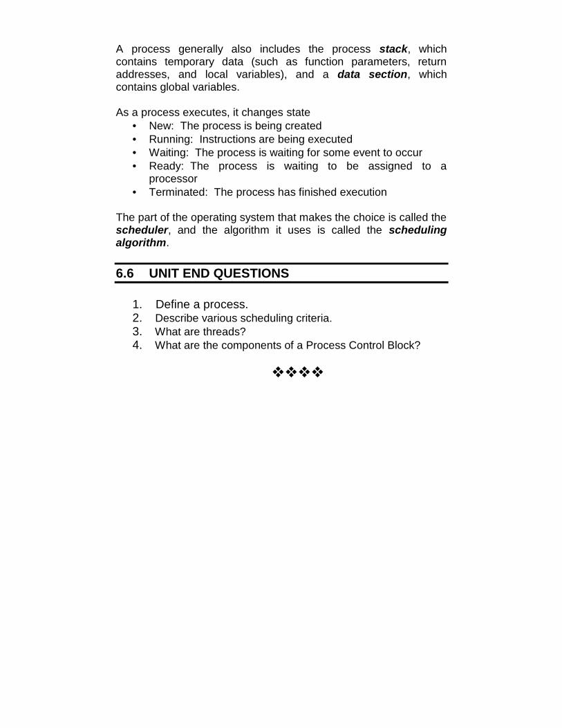
A process generally also includes the process stack, whichcontains temporary data (such as function parameters, returnaddresses, and local variables), and a data section, whichcontains global variables.
As a process executes, it changes state• New: The process is being created• Running: Instructions are being executed• Waiting: The process is waiting for some event to occur• Ready: The process is waiting to be assigned to a
processor• Terminated: The process has finished execution
The part of the operating system that makes the choice is called thescheduler, and the algorithm it uses is called the schedulingalgorithm.
6.6 UNIT END QUESTIONS
1. Define a process.2. Describe various scheduling criteria.3. What are threads?4. What are the components of a Process Control Block?

7
PROCESS SCHEDULINGALGORITHMS
Unit Structure7.0 Objectives7.1 Introduction7.2 Scheduling Algorithms
7.2.1 First-come, First-served (fcfs) scheduling7.2.2 Shortest job first scheduling7.2.3 Priority scheduling7.2.4 Round robin scheduling7.2.5 Multilevel queue scheduling7.2.6 Multilevel feedback queue scheduling
7.3 Let us sum up7.4 Unit end questions
7.0 OBJECTIVES
After reading this unit you will be able to:• Discuss various scheduling algorithms
7.1 INTRODUCTION
Scheduling algorithms in Modern Operating Systems are used to:• Maximize CPU utilization• Maximize throughput• Minimize turnaround time• Minimize waiting time• Minimize response time
7.2 SCHEDULING ALGORITHMS
7.2.1 FIRST-COME, FIRST-SERVED (FCFS) SCHEDULING
Requests are scheduled in the order in which they arrive inthe system. The list of pending requests is organized as a queue.The scheduler always schedules the first request in the list. An
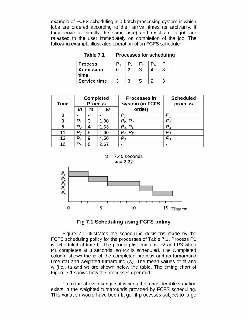
example of FCFS scheduling is a batch processing system in whichjobs are ordered according to their arrival times (or arbitrarily, ifthey arrive at exactly the same time) and results of a job arereleased to the user immediately on completion of the job. Thefollowing example illustrates operation of an FCFS scheduler.
Table 7.1 Processes for scheduling
Process P1 P2 P3 P4 P5Admissiontime
0 2 3 4 8
Service time 3 3 5 2 3
CompletedProcessTime
id ta w
Processes insystem (in FCFS
order)
Scheduledprocess
0 - - - P1 P13 P1 3 1.00 P2, P3 P26 P2 4 1.33 P3, P4 P3
11 P3 8 1.60 P4, P5 P413 P4 9 4.50 P5 P516 P5 8 2.67 - -
ta = 7.40 secondsw = 2.22
Fig 7.1 Scheduling using FCFS policy
Figure 7.1 illustrates the scheduling decisions made by theFCFS scheduling policy for the processes of Table 7.1. Process P1is scheduled at time 0. The pending list contains P2 and P3 whenP1 completes at 3 seconds, so P2 is scheduled. The Completedcolumn shows the id of the completed process and its turnaroundtime (ta) and weighted turnaround (w). The mean values of ta andw (i.e., ta and w) are shown below the table. The timing chart ofFigure 7.1 shows how the processes operated.
From the above example, it is seen that considerable variationexists in the weighted turnarounds provided by FCFS scheduling.This variation would have been larger if processes subject to large

turnaround times were short -e.g., the weighted turnaround of P4would have been larger if its execution requirement had been 1second or 0.5 second.
7.2.2 SHORTEST JOB FIRST SCHEDULING
Shortest Job First scheduling assumes the run times areknown in advance. In an insurance company, for example, peoplecan predict quite accurately how long it will take to run a batch of1000 claims, since similar work is done every day. When severalequally important jobs are sitting in the input queue waiting to bestarted, the scheduler picks the shortest job first. Look at Fig. 7.7.Here we find four jobs A, B, C, and D with run times of 8, 4, 4, and4 minutes, respectively. By running them in that order, theturnaround time for A is 8 minutes, for B is 12 minutes, for C is 16minutes, and for D is 20 minutes for an average of 14 minutes.
8 4 4 4 4 4 48
B C D A
(a) (b)
Fig 7.2 (a) Running four jobs in the original order (b) Running them in shortest job first order
Now let us consider running these four jobs using shortest jobfirst, as shown in Fig. 7.2 (b). The turnaround times are now 4, 8,12, and 20 minutes for an average of 11 minutes. Shortest job firstis probably optimal. Consider the case of four jobs, with run timesof A, B, C, and D, respectively. The first job finishes at time a, thesecond finishes at time a + b, and so on. The mean turnaround timeis (4a + 3b + 2c + d)/4. It is clear that A contributes more to theaverage than the other times, so it should be the shortest job, withb next, then C, and finally D as the longest as it affects only its ownturnaround time. The same argument applies equally well to anynumber of jobs.
It is worth pointing out that shortest job first is only optimalwhen all the jobs are available simultaneously. As acounterexample, consider five jobs, A through E, with run times of2, 4, 1, 1, and 1, respectively. Their arrival times are 0, 0, 3, 3, and3. Initially, only A or B can be chosen, since the other three jobshave not arrived yet. Using shortest job first we will run the jobs inthe order A, B, C, D, E, for an average wait of 4.7. However,running them in the order B, C, D, E, A has an average wait of 4.4.
7.2.3 PRIORITY SCHEDULINGThe basic idea is straightforward: each process is assigned a
priority, and priority is allowed to run. Equal-Priority processes are
A B C D
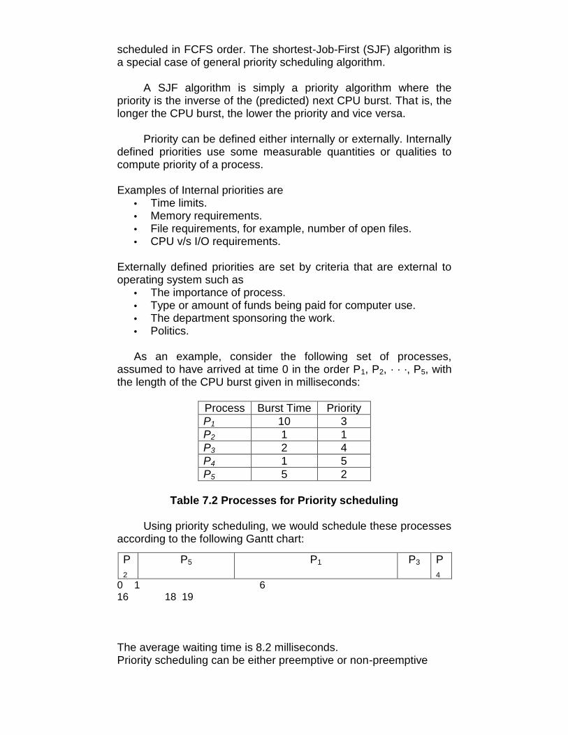
scheduled in FCFS order. The shortest-Job-First (SJF) algorithm isa special case of general priority scheduling algorithm.
A SJF algorithm is simply a priority algorithm where thepriority is the inverse of the (predicted) next CPU burst. That is, thelonger the CPU burst, the lower the priority and vice versa.
Priority can be defined either internally or externally. Internallydefined priorities use some measurable quantities or qualities tocompute priority of a process.
Examples of Internal priorities are• Time limits.• Memory requirements.• File requirements, for example, number of open files.• CPU v/s I/O requirements.
Externally defined priorities are set by criteria that are external tooperating system such as
• The importance of process.• Type or amount of funds being paid for computer use.• The department sponsoring the work.• Politics.
As an example, consider the following set of processes,assumed to have arrived at time 0 in the order P1, P2, · · ·, P5, withthe length of the CPU burst given in milliseconds:
Process Burst Time PriorityP1 10 3P2 1 1P3 2 4P4 1 5P5 5 2
Table 7.2 Processes for Priority scheduling
Using priority scheduling, we would schedule these processesaccording to the following Gantt chart:
P2
P5 P1 P3 P4
0 1 616 18 19
The average waiting time is 8.2 milliseconds.Priority scheduling can be either preemptive or non-preemptive

• A preemptive priority algorithm will preemptive the CPU if thepriority of the newly arrival process is higher than the priorityof the currently running process.
• A non-preemptive priority algorithm will simply put the newprocess at the head of the ready queue.
A major problem with priority scheduling is indefinite blocking orstarvation. A solution to the problem of indefinite blockage of thelow-priority process is aging. Aging is a technique of graduallyincreasing the priority of processes that wait in the system for along period of time.
7.2.4 ROUND ROBIN SCHEDULINGOne of the oldest, simplest, fairest and most widely used
algorithm is round robin (RR). In the round robin scheduling,processes are dispatched in a FIFO (First-In-First-Out) manner butare given a limited amount of CPU time called a time-slice or aquantum.
If a process does not complete before its CPU-time expires,the CPU is preempted and given to the next process waiting in aqueue. The preempted process is then placed at the back of theready list.
Figure 7.3 summarizes operation of the RR scheduler with δ =1 second for the five processes shown in Table 7.3. The schedulermakes scheduling decisions every second. The time when adecision is made is shown in the first row of the table in the top halfof Figure 7.3. The next five rows show positions of the fiveprocesses in the ready queue. A blank entry indicates that theprocess is not in the system at the designated time. The last rowshows the process selected by the scheduler; it is the processoccupying the first position in the ready queue.
Table 7.3 Processes for RR scheduling
ta = 7.4 seconds, w = 2.32,c: completion time of a process

Consider the situation at 2 seconds. The scheduling queuecontains P2 followed by P1. Hence P2 is scheduled. Process P3arrives at 3 seconds, and is entered in the queue. P2 is alsopreempted at 3 seconds and it is entered in the queue. Hence thequeue has process P1 followed by P3 and P2, so P1 is scheduled.
Fig 7.3 Scheduling using Round-robin policy with time-slicing
The turnaround times and weighted turnarounds of theprocesses are as shown in the right part of the table. The c columnshows completion times. The turnaround times and weightedturnarounds are inferior to those given by the non-preemptivepolicies because the CPU time is shared among many processesbecause of time-slicing.
It can be seen that processes P2, P3, and P4, which arrive ataround the same time, receive approximately equal weightedturnarounds. P4 receives the worst weighted turnaround becausethrough most of its life it is one of three processes present in thesystem. P1 receives the best weighted turnaround because no otherprocess exists in the system during the early part of its execution.Thus weighted turnarounds depend on the load in the system.
Round Robin Scheduling is preemptive (at the end of time-slice) therefore it is effective in time-sharing environments in whichthe system needs to guarantee reasonable response times forinteractive users.
The only interesting issue with round robin scheme is thelength of the quantum. Setting the quantum too short causes toomany context switches and lower the CPU efficiency. On the otherhand, setting the quantum too long may cause poor response timeand appoximates FCFS.
In any event, the average waiting time under round robinscheduling is often quite long.
7.2.5 MULTILEVEL QUEUE SCHEDULING

A multilevel queue scheduling algorithm partitions the Readyqueue is partitioned into separate queues:
• foreground (interactive)• background (batch)
Fig 7.4 Multilevel queue scheduling
In a multilevel queue scheduling processes are permanentlyassigned to one queues. The processes are permanently assignedto one another, based on some property of the process, such as
• Memory size• Process priority• Process type
Algorithm choose the process from the occupied queue that hasthe highest priority, and run that process either
• Preemptive or• Non-preemptiveEach queue has its own scheduling algorithm• foreground – RR• background – FCFS
Possibility IIf each queue has absolute priority over lower-priority queues
then no process in the queue could run unless the queue for thehighest-priority processes were all empty.
For example, in the above figure no process in the batchqueue could run unless the queues for system processes,interactive processes, and interactive editing processes will allempty.
Possibility II

If there is a time slice between the queues then each queuegets a certain amount of CPU times, which it can then scheduleamong the processes in its queue. For instance;
• 80% of the CPU time to foreground queue using RR.• 20% of the CPU time to background queue using FCFS.
Since processes do not move between queues so, this policyhas the advantage of low scheduling overhead, but it is inflexible.
7.2.6 MULTILEVEL FEEDBACK QUEUE SCHEDULING
Here, processes are not permanently assigned to a queue onentry to the system. Instead, they are allowed to move betweenqueues. The idea is to separate processes with different CPU burstcharacteristics. If a process uses too much CPU time, it will bemoved to a lower priority queue. Similarly, a process that waits toolong in a low priority queue will be moved to a higher priority queue.This form of aging prevents starvation.
Fig 7.5 Multilevel Feedback Queue Scheduling
Fig 7.6 MFQ Scheduling architecture
Multilevel feedback queue scheduler is characterized bythe following parameters:

1. Number of queues 2. Scheduling g algorithms for each queue 3. Method used to determine when to upgrade a process4. Method used to determine when to demote a process5. Method used to determine which queue a process will
enter when that process needs service
Example:Three queues:
1. Q0 – time quantum 8 milliseconds 2. Q1 – time quantum 16 milliseconds 3. Q2 – FCFS
Fig 7.8 MFQ scheduling example
Scheduling:1. A new job enters queue Q0 which is served FCFS. When
it gains CPU, job receives 8 milliseconds. If it does not finish in8 milliseconds, job is moved to queue Q1.
2. At Q1 job is again served FCFS and receives 16additional milliseconds. If it still does not complete, it ispreempted and moved to queue Q2.
7.3 LET US SUM UP
• The scheduler always schedules the first request in the list.
• Shortest Job First scheduling assumes the run times are knownin advance.
• It is worth pointing out that shortest job first is only optimal whenall the jobs are available simultaneously.
• The shortest-Job-First (SJF) algorithm is a special case ofgeneral priority scheduling algorithm.
• Priority can be defined either internally or externally.

• A major problem with priority scheduling is indefinite blocking orstarvation.
• In the round robin scheduling, processes are dispatched in aFIFO (First-In-First-Out) manner but are given a limited amountof CPU time called a time-slice or a quantum.
• Round Robin Scheduling is preemptive (at the end of time-slice).
• A multilevel queue scheduling algorithm partitions the Readyqueue is partitioned into separate queues
• In MFQ scheduling, processes are not permanently assigned toa queue on entry to the system.
7.4 UNIT END QUESTIONS
1. Definea. Quantumb. Aging
2. Give an example of First-Come, First-Served Scheduling.3. What is the difference between Multilevel Queue
Scheduling and Multilevel Feedback Queue Scheduling?4. Describe the architecture of MFQ scheduling with the help
of diagrams.5. State the criteria for internal and external priorities.

8
PROCESS AND THREADMANAGEMENT
Unit Structure8.0 Objectives8.1 Introduction8.2 Operations on processes
8.2.1 Process creation8.2.2 Process termination8.2.3 Cooperating processes
8.3 Interprocess communication8.3.1 Message passing system
8.3.1.1 Direct communication8.3.1.2 Indirect communication8.3.1.3 Synchronisation8.3.1.4 Buffering
8.4 Multithreading models8.4.1 Many-to-one Model8.4.2 One-to-one Model8.4.3 Many-to-many model
8.5 Threading Issues8.5.1 Semantics of fork() and exec() system calls8.5.2 Thread Cancellation8.5.3 Signal Handling8.5.4 Thread pools8.5.5 Thread specific data8.5.6 Scheduler activations
8.6 Thread scheduling8.6.1 Contention scope8.6.2 Pthread scheduling
8.7 Let us sum up8.8 Unit end questions
8.0 OBJECTIVES

root
Page daemon swapper init
User2User1 User3
…… …
A tree of processes on a typical UNIX system
After reading this unit you will be able to:• Describe the creation & termination of a process• Study various interprocess communications• Introduce the notion of a thread- a fundamental unit of CPU
utilization that forms the basis of multithreaded computersystems.
• Examine issues related to multithreaded programming.
8.1 INTRODUCTION
Generally, when a thread finishes performing a task, thread issuspended or destroyed. Writing a program where a processcreates multiple threads is called multithread programming. It is theability by which an OS is able to run different parts of the sameprogram simultaneously. It offers better utilization of processorsand other system resources. For example, word processor makesuse of multi-threading – in the foreground it can check spelling aswell as save document in the background.
8.2 OPERATIONS ON PROCESS
8.2.1 PROCESS CREATION
A process may create several new processes, via a create-process system call, during the course of execution. The creatingprocess is called a parent process, whereas the new processesare called the children of that process. Each of these newprocesses may in turn create other processes, forming a tree ofprocesses as shown below.
Fig 8.1
In general, a process will need certain resources (such asCPU time, memory, files, I/O devices) to accomplish its task. Whenthe process creates a sub process, that sub process may be able toobtain its resources directly from the OS, or it may be controlled toa subset of the resources of the parent process. The parent mayhave to partition its resources among its children, or it may be ableto share some resources (such as memory or files) among severalof its children. Restricting a child process to a subset of theparent’s resources prevent any process from overloading thesystem by creating too many sub processes.
When a process is created it obtains along with the resources,initialization data (or input from the file, say F1) that may be passedalong from the parent process to the child process. It may also getthe name of the output device. New process may get two openfiles, F1 and the terminal device, and may just need to transfer thedatum between the two.
When a process creates a new process, two possibilities exist interms of execution:
1. The parent continues to execute concurrently with itschildren.
2. The parent waits until some or all of its children haveterminated.
There are also two possibilities in terms of the address space of thenew process:
1. The child process is a duplicate of the parent process.

2. The child process has a program loaded into it.
Following are some reasons for creation of a process:• User logs on.• User starts a program.• Operating systems creates process to provide service, e.g.,
to manage printer.• Some program starts another process, e.g., Netscape
calls xv to display a picture.
In UNIX, each process is identified by its process identifier(PID), which is a unique integer. A new process is created by thefork system call. The new process consists of a copy of the addressspace of the original process which helps the parent process tocommunicate easily with its child process. Both processes (theparent & the child) continue execution at the instruction after thefork system call, with one difference: The return code for the forksystem call is zero for the new (child) process, whereas the(nonzero) process identifier of the child is returned to the parent.
Fig 8.2 UNIX Process Creation
To understand the above possibilities, consider the following Cprogram:
int main() {Pid_t pid;
/* fork another process */

pid = fork();if (pid < 0) { /* error occurred */
fprintf(stderr, "Fork Failed");exit(-1);
}else if (pid == 0) { /* child process */
execlp("/bin/ls", "ls", NULL);}else { /* parent process */
/* parent will wait for the child to complete */wait (NULL);printf ("Child Complete");exit(0);
}}
The parent creates a child process using the fork system call.We now have two different processes running a copy of the sameprogram. The value of the pid for the child process is zero; that forthe parent is an integer value greater than zero. The child processoverlays its address space with the UNIX command /bin/ls (used toget a directory listing) using the execlp system call. The parentwaits for the child process to complete with the wait system call.When the child process completes, the parent process resumes thecall to wait where it completes using the exit system call.
8.2.2 PROCESS TERMINATIONA process terminates when it finishes executing its final
statement and asks the OS to delete it by using the exit systemcall. At that point, the process may return data (output) to its parentprocess (via the wait system all). All the resources of the process,including physical and virtual memory, open files, and I/O buffersare deallocated by the OS.
A process can cause the termination of another process via anappropriate system call such as abort. Usually, only the parent ofthe process that is to be terminated can invoke such a system callotherwise you can arbitrarily kill each other’s jobs.
A parent may terminate the execution of one of its children forthe following reasons:
• The child has exceeded its usage of some of the resourcesthat it has been allocated. This requires the parent to have amechanism to inspect the state of its children.
• The task assigned to the child is no longer required.

• The parent is exiting, and the OS does not allow a child tocontinue if its parent terminates. On such systems, if aprocess terminates (either normally or abnormally), then allits children must also be terminated. This is referred to asCascading Termination, and is normally initiated by theOS. In the case of UNIX, if the parent terminates, however,all its children have assigned as the new parent the initprocess. Thus, the children still have a parent to collect theirstatus and execution statistics.
The new process terminates the existing process, usually due tofollowing reasons:
• Normal ExitMost processes terminates because they have done
their job. This call is exist in UNIX.
• Error ExitWhen process discovers a fatal error. For example, a
user tries to compile a program that does not exist.
• Fatal ErrorAn error caused by process due to a bug in program for
example, executing an illegal instruction, referring non-existing memory or dividing by zero.
• Killed by another ProcessA process executes a system call telling the Operating
Systems to terminate some other process. In UNIX, this callis kill. In some systems when a process kills all processes itcreated are killed as well (UNIX does not work this way).
8.2.2 COOPERATING PROCESSES
A process is independent if it cannot affect or be affected bythe other processes executing in the system. On the other hand, aprocess is cooperating if it can affect or be affected by the otherprocesses executing in the system. Process cooperation is requiredfor the following reasons:
• Information sharing:Several users may be interested in the same piece of
information (for instance, a shared file), we must provide anenvironment to allow concurrent access to these types ofresources.
• Computation speedup:If we want a particular task to run faster, we must break
it into subtasks, each of which will be executing in parallelwith the others. Such a speedup can be achieved only if the
computer has multiple processing elements (such as CPUsor I/O channels).
• Modularity:To construct the system in a modular fashion, dividing
the system functions into separate processes or threads.
• Convenience:Individual user may have many tasks to work at one
time. For instance, a user may be editing, printing, andcompiling in parallel.
Concurrent execution of cooperating processes requiresmechanism that allow processes to communicate with one anotherand to synchronize their actions.
8.3 INTERPROCESS COMMUNICATION
The OS provides the means for cooperating processes tocommunicate with each other via an interprocess communication(IPC) facility. IPC provides a mechanism to allow processes tocommunicate and to synchronize their actions without sharing thesame address space. IPC is particularly useful in a distributedenvironment where the communicating processes may reside ondifferent computers connected with a network e.g. chat programused on the world wide web. IPC is best provided by a message-passing system, and the message systems can be defined inmany ways.
8.3.1 MESSAGE PASSING SYSTEM
Message system allows processes to communicate with oneanother without the need to resort to shared data. Services areprovided as ordinary user processes operate outside the kernel.Communication among the user processes is accomplishedthrough the passing of messages. An IPC facility provides at leasttwo operations: send (message) and receive (message). Messagessent by a process can be of either fixed or variable size.
If processes P and Q want to communicate, they must sendmessages to send and receive from each other; acommunication link must exist between them. There are severalmethods for logical implementation of a link as follows:
• Direct or indirect communication.• Symmetric or asymmetric communication.• Automatic or explicit buffering.• Send by copy or send by reference.• Fixed-sized or variable-sized message.
8.3.1.1 DIRECT COMMUNICATION

Each process that wants to communicate must explicitly namethe recipient or sender of the communication. The send andreceive primitives are defied as:
• send (P, message) – Send a message to process P.• receive (Q, message)–Receive a message from process
Q.
A communication link in this scheme has the following properties:• A link is established automatically between every pair of
processes that want to communicate. The processes needto know only each other’s identity to communicate.
• A link is associated with exactly two processes.• Exactly one link exists between each pair of processes.
This scheme exhibits symmetry in addressing; that is, boththe sender and the receiver processes must name the other tocommunicate.
A variant of this scheme employs asymmetry in addressing.Only the sender names the recipient; the recipient is not required toname the sender. In this scheme, the send and receive primitivesare as follows:
• send (P, message) – Send a message to process P.• receive (id, message) – Receive a message from any
process; the variable id is set to the name of the processwith which communication has taken place.
The disadvantage in both schemes:
Changing the name of a process may necessitate examiningall other process definitions. All references to the old name must befound, so that they can be modified to the new name. This situationis not desirable from the viewpoint of separate compilation.
8.3.1.2 INDIRECT COMMUNICATIONThe messages are sent to and received from mailboxes, or
ports. Each mailbox has a unique identification. Two processescan communicate only if they share a mailbox. The send andreceive primitives are defined as follows:
• send (A, message) - Send a message to mailbox A.• receive (A,message) – Receive a message from mailbox A.
In this scheme, a communication link has the following properties:
• A link is established between a pair of processes only if bothmembers of the pair have a shared mailbox.
• A link may be associated with more than two processes.

• A number of different links may exist between each pair ofcommunicating processes, with each link corresponding toone mailbox.
If processes P1, P2 and P3 all share mailbox A. Process P1 sends amessage to A, while P2 and P3 each execute and receive from A.The process to receive the message depends on one of thescheme that:
• Allows a link to be associated with at most two processes.• Allows utmost one process at a time to execute a receive
operation.• Allows the system to select arbitrarily which process will
receive the message (that is either P2 or P3, but not both, willreceive the message). The system may identify the receiverto the sender.
If the mailbox is owned by process (that is, the mailbox is part ofthe address space of the process), then we distinguish between theowner (who can only receive messages through this mailbox) andthe user (who can only send messages to the mailbox).
When a process that owns a mailbox terminates, the mailboxdisappears. Any process that subsequently sends a message tothis mailbox must be notified that the mailbox no longer exists. Onthe other hand, a mailbox owned by the OS is independent and isnot attached to any particular process. The OS then must provide amechanism that allows a process to do the following:
• Create a new mailbox.• Send and receive messages through the mailbox.• Delete a mailbox.• Process who create a mailbox is the owner by default and
receives messages through this mail box. Ownership can bechanged by OS through appropriate system calls to providemultiple receivers for each mailbox.
8.3.1.3 SYNCHRONIZATIONThe send and receive system calls are used to communicate
between processes but there are different design options forimplementing these calls. Message passing may be eitherblocking or non-blocking - also known as synchronous andasynchronous.
• Blocking send:The sending process is blocked until the message is receivedby the receiving process or by the mailbox.
• Non-blocking send:
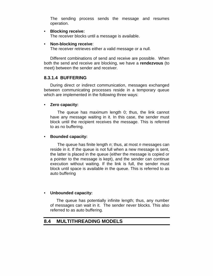
The sending process sends the message and resumesoperation.
• Blocking receive:The receiver blocks until a message is available.
• Non-blocking receive:The receiver retrieves either a valid message or a null.
Different combinations of send and receive are possible. Whenboth the send and receive are blocking, we have a rendezvous (tomeet) between the sender and receiver.
8.3.1.4 BUFFERINGDuring direct or indirect communication, messages exchanged
between communicating processes reside in a temporary queuewhich are implemented in the following three ways:
• Zero capacity:
The queue has maximum length 0; thus, the link cannothave any message waiting in it. In this case, the sender mustblock until the recipient receives the message. This is referredto as no buffering.
• Bounded capacity:
The queue has finite length n; thus, at most n messages canreside in it. If the queue is not full when a new message is sent,the latter is placed in the queue (either the message is copied ora pointer to the message is kept), and the sender can continueexecution without waiting. If the link is full, the sender mustblock until space is available in the queue. This is referred to asauto buffering
• Unbounded capacity:
The queue has potentially infinite length; thus, any numberof messages can wait in it. The sender never blocks. This alsoreferred to as auto buffering.
8.4 MULTITHREADING MODELS

Fig 8.3 Single threaded and multithreaded processes
Support for threads may be provided either at the user level,for or by the kernel, for threads. User threads are supported abovethe kernel and are managed without kernel support, whereas kernelthreads are supported and managed directly by the operatingsystem. A relationship exists between user threads and kernelthreads.
There are mainly three types of multithreading models availablefor user and kernel threads.
8.4.1 Many-to-One Model:

Fig 8.4 Many-to-One model
The many-to-one model maps many user-level threads to onekernel thread. Thread management is done in user space, so it isefficient, but the entire process will block if a thread makes ablocking system call. Because only one thread can access thekernel at a time, multiple threads are unable to run in parallel onmultiprocessors. Green threads- a thread library available forSolaris uses this model. OS that do not support the kernel threadsuse this model for user level threads.
8.4.2 One-to-One Model:
Fig 8.5 One-to-One model
Maps each user thread to a kernel thread. Allows anotherthread to run when a thread makes a blocking system call. Alsoallows multiple threads to run in parallel on multiprocessors.Drawback is that creating a user thread requires creating thecorresponding kernel thread. Because the overhead of creatingkernel threads can burden the performance of an application, andtherefore, restriction has to be made on creation of number ofthreads. Window NT, Windows 2000, and OS/2 implement thismodel.
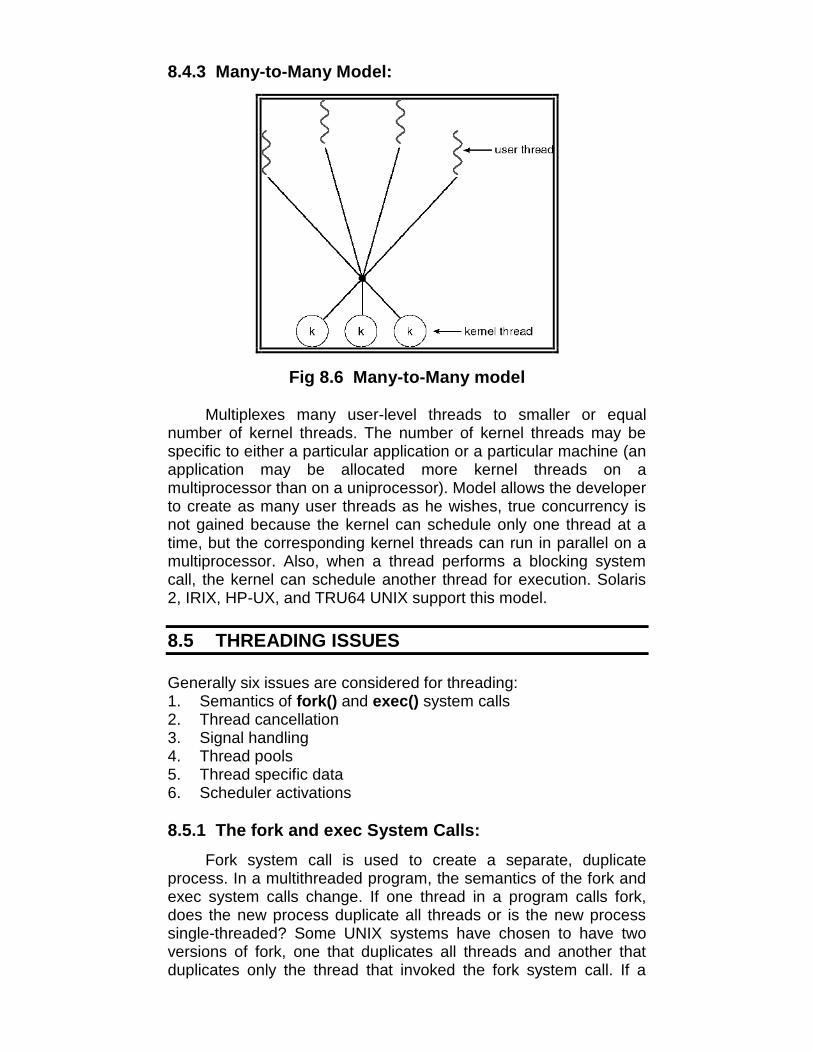
8.4.3 Many-to-Many Model:
Fig 8.6 Many-to-Many model
Multiplexes many user-level threads to smaller or equalnumber of kernel threads. The number of kernel threads may bespecific to either a particular application or a particular machine (anapplication may be allocated more kernel threads on amultiprocessor than on a uniprocessor). Model allows the developerto create as many user threads as he wishes, true concurrency isnot gained because the kernel can schedule only one thread at atime, but the corresponding kernel threads can run in parallel on amultiprocessor. Also, when a thread performs a blocking systemcall, the kernel can schedule another thread for execution. Solaris2, IRIX, HP-UX, and TRU64 UNIX support this model.
8.5 THREADING ISSUES
Generally six issues are considered for threading:1. Semantics of fork() and exec() system calls2. Thread cancellation3. Signal handling4. Thread pools5. Thread specific data6. Scheduler activations
8.5.1 The fork and exec System Calls:Fork system call is used to create a separate, duplicate
process. In a multithreaded program, the semantics of the fork andexec system calls change. If one thread in a program calls fork,does the new process duplicate all threads or is the new processsingle-threaded? Some UNIX systems have chosen to have twoversions of fork, one that duplicates all threads and another thatduplicates only the thread that invoked the fork system call. If a

thread invokes the exec system call, the program specified in theparameter to exec will replace the entire process-including allthreads and LWPs.
8.5.2 Thread cancellation:It is the task of terminating thread before it has completed.
E.g., if multiple threads are concurrently searching through adatabase and one thread returns the result, the remaining threadsmight be cancelled. A thread that is to be cancelled is often referredto as the target thread.
Cancellation of threads may be one of the following types:
1) Asynchronous cancellation: One thread immediatelyterminates the target thread. The OS will often reclaim systemresources from a cancellation thread, but often will not reclaimall resources.
2) Deferred cancellation: The target thread can periodically checkif it should terminate, allowing the target thread an opportunity toterminate itself in an orderly fashion. This allows a thread tocheck if it should be canceled at a point when it can safely becancelled. Pthread refers to such points as cancellationpoints.
8.5.3 Signal Handling:A signal is used in UNIX systems to notify a process that a
particular event has occurred. A signal may be received eithersynchronously or asynchronously depending upon the source andthe reason for the event being signaled.
All signals follow the same pattern:1. A signal is generated by the occurrence of a particular event.2. A generated signal is delivered to a process.3. Once delivered, the signal must be handled.
Every signal may be handled by one of two possible handlers:1. A default signal handler that is run by the kernel.2. A user-defined signal handler.
The following options exist in delivering the signals in amultithreaded programs:
1. Deliver the signal to the thread to which the signal applies.2. Deliver the signal to every thread in the process.3. Deliver the signal to certain threads in the process4. Assign a specific thread to receive all signals for the
process.
8.5.4 Thread pools:

The general idea behind a thread pool is to create a numberof threads at process startup and place them into a pool, wherethey sit and wait for work. When a server receives a request, itawakens a thread from this pool- if one is available-passing it therequest to service. Once the thread completes its service, it returnsto the pool awaiting more work. If the pool contains no availablethread, the server waits until one becomes free. The number ofthreads in the pool depends upon the number of CPUs, the amountof physical memory, and the expected number of concurrent clientrequests.
In particular, the benefits of thread pools are:1. It is usually faster to service a request with an existing thread
than waiting to create a thread.
2. A thread pool limits the number of threads that exist at any onepoint. This is particularly important on systems that cannotsupport a large number of concurrent threads.
8.5.5 Thread specific data:Threads belonging to a process share the data of the process.
This sharing of data provides one of the benefits of multithreadedprogramming. However, each thread might need its own copy ofcertain data in some circumstances, called as thread-specificdata. Most thread libraries- including Win32 and Pthreads-providesome form of support for thread specific data.
8.5.6 Scheduler Activations:
Communication between the kernel and the thread library maybe required by the many-to-many and two-level models. Suchcoordination allows the number of kernel threads to be dynamicallyadjusted to help ensure the best performance. Many systemsimplementing either the many-to-many or the two-level model placean intermediate data structure between the user and kernelthreads. This data structure-typically known as a lightweightprocess, or LWP-is shown in Figure 8.7.

Fig 8.7 Lightweight Process (LWP)
To the user-thread library, the LWP appears to be a virtualprocessor on which the application can schedule a user thread torun. Each LWP is attached to a kernel thread, and it is kernelthreads that the operating system schedules to run on physicalprocessors. If a kernel thread blocks (such as while waiting for ani/o operation to complete), the LWP blocks as well. Up the chain,the user-level thread attached to the LWP also blocks. Anapplication may require any number of LWPs to run efficiently.
8.6 THREAD SCHEDULING
User-level threads are managed by a thread library, and thekernel is unaware of them. To run on a CPU, user-level threadsmust ultimately be mapped to an associated kernel-level thread,although this mapping may be indirect and may use a lightweightprocess (LWP).
8.6.1 CONTENTION SCOPESystems implementing many-to-one and many-to-many
models, the thread library schedules user-level threads to run on anavailable LWP, a scheme known as process-contention scope(PCS), since competition for the CPU takes place among threadsbelonging to the same process.
To decide which kernel thread to schedule onto a CPU, thekernel uses system-contention scope (SCS). Competition for theCPU with SCS scheduling takes place among all threads in thesystem. Systems using the one-to-one model, such as WindowsXP, Solaris, and Linux, schedule threads using only SCS.
Typically, PCS is done according to priority-the schedulerselects the runnable thread with the highest priority to run. User-level thread priorities are set by the programmer and are not

adjusted by the thread library, although some thread libraries mayallow the programmer to change the priority of a thread. It isimportant to note that PCS will typically prompt the thread currentlyrunning in favor of a higher-priority thread; however, there is noguarantee of time slicing among threads of equal priority.
8.6.2 PTHREAD SCHEDULINGPthread API allows specifying either PCS or SCS during
thread creation. Pthreads identifies the following contention scopevalues:
PTHREAD_SCOPE_PROCESS schedules threads using PCSscheduling.PTHREAD_SCOPE_SYSTEM schedules threads using SCSscheduling.
On systems implementing the many-to-many model, thePTHREAD_SCOPE_PROCESS policy schedules user-levelthreads onto available LWPs. The number of LWPs is maintainedby the thread library, perhaps using scheduler activations. ThePTHREAD_SCOPE_SYSTEM scheduling policy will create andbind an LWP for each user-level thread on many-to-many systems,effectively mapping threads using the one-to-one policy. ThePthread IPC provides two functions for getting-and setting-thecontention scope policy:
pthread_attr_setscope(pthread_attr_t *attr, int scope)pthread_attr_getscope(pthread_attr_t *attr, int *scope)
The first parameter for both functions contains a pointer to theattribute set for the thread. The second parameter for thepthread_attr_setscope() function is passed either thePTHREAD_SCOPE_SYSTEM or thePTHREAD_SCOPE_PROCESS value, indicating how thecontention scope is to be set. In the case ofpthread_attr_getscope(), this second parameter contains a pointerto an int value that is set to the current value of the contentionscope. If an error occurs, each of these functions returns a non-zero value.
8.7 LET US SUM UP
• The creating process is called a parent process, whereas thenew processes are called the children of that process.
• A process terminates when it finishes executing its finalstatement and asks the OS to delete it by using the exit systemcall.
• IPC provides a mechanism to allow processes to communicateand to synchronize their actions without sharing the sameaddress space.
• If processes P and Q want to communicate, they must sendmessages to send and receive from each other; acommunication link must exist between them.
• Message passing may be either blocking or non-blocking - alsoknown as synchronous and asynchronous.
• There are mainly three types of multithreading models availablefor user and kernel threads.
• Generally six issues are considered for threading.
8.8 UNIT END QUESTIONS
1. Define :(a) Thread-specific Data(b) Multithread programming(c) Parent Process
2. Discuss different threading issues.3. What is meant by cooperating processes?4. Write a short note on Message Passing System.5. How is a process created?
9CLIENT-SERVER SYSTEMS
Unit Structure9.0 Objectives9.1 Introduction9.2 Communication in client-server system
9.2.1 Sockets9.2.2 Remote procedure calls (RPC)9.2.3 Pipes
9.3 The critical-section problem9.4 Peterson’s solution9.5 Semaphores9.6 Let us sum up9.7 Unit end questions
9.0 OBJECTIVES
After reading this unit you will be able to:• Describe the communication between Client-Server
systems.• Distinguish between various pipes.• Learn Peterson’s solution for achieving mutual exclusion• Study the concept of Semaphores
9.1 INTRODUCTION
The message passing paradigm realizes exchange ofinformation among processes without using shared memory. Thisfeature makes it useful in diverse situations such as incommunication between OS functionalities in a microkernel-basedOS, in client–server computing, in higher-level protocols forcommunication, and in communication between tasks in a parallelor distributed program.
Amoeba is a distributed operating system developed at theVrije Universiteit in the Netherlands during the 1980s. The primarygoal of the Amoeba project is to build a transparent distributedoperating system that would have the look and feel of a standard

time-sharing OS like UNIX. Another goal is to provide a test-bed fordistributed and parallel programming.
Amoeba provides kernel-level threads and two communicationprotocols. One protocol supports the client–server communicationmodel through remote procedure calls (RPCs), while the otherprotocol provides group communication. For actual messagetransmission, both these protocols use an underlying Internetprotocol called the fast local Internet protocol (FLIP).
9.2 COMMUNICATION IN CLIENT-SERVER SYSTEM
Three strategies for communication in client-server systems are:1. Sockets,2. Remote procedure calls (RPCs), and3. Pipes.
9.2.1 SOCKETSA socket is defined as an endpoint for communication. A pair
of processes communicating over a network employ a pair ofsockets-one for each process. A socket is identified by an IPaddress concatenated with a port number.
In general, sockets use a client-server architecture. Theserver waits for incoming client requests by listening to a specifiedport. Once a request is received, the server accepts a connectionfrom the client socket to complete the com1ection. Serversimplementing specific services (such as telnet, FTP, and I-HTP)listen to well-known ports (a telnet server listens to port 23; an FTPserver listens to port 21; and a Web, or HTTP, server listens to port80). All ports below 1024 are considered ·well known; we can usethem to implement standard services. When a client processinitiates a request for a connection, it is assigned a port by its hostcomputer. This port is some arbitrary number greater than 1024.
For example, if a client on host X with IP address 146.86.5.20wishes to establish a connection with a Web server (which islistening on port 80) at address 161.25.19.8, host X may beassigned port 1625. The connection will consist of a pair of sockets:(146.86.5.20:1625) on host X and (161.25.19.8:80) on the Webserver. This situation is illustrated in Figure 9.1. The packetstraveling between the hosts are delivered to the appropriateprocess based on the destination port number.
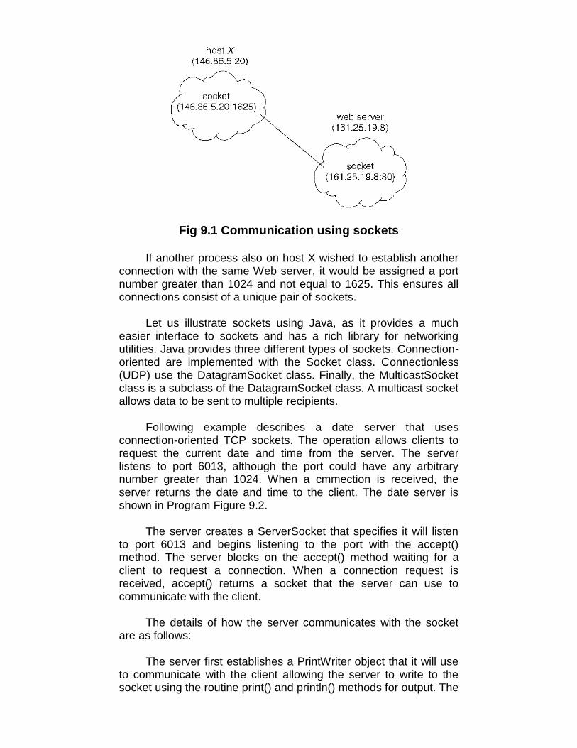
Fig 9.1 Communication using sockets
If another process also on host X wished to establish anotherconnection with the same Web server, it would be assigned a portnumber greater than 1024 and not equal to 1625. This ensures allconnections consist of a unique pair of sockets.
Let us illustrate sockets using Java, as it provides a mucheasier interface to sockets and has a rich library for networkingutilities. Java provides three different types of sockets. Connection-oriented are implemented with the Socket class. Connectionless(UDP) use the DatagramSocket class. Finally, the MulticastSocketclass is a subclass of the DatagramSocket class. A multicast socketallows data to be sent to multiple recipients.
Following example describes a date server that usesconnection-oriented TCP sockets. The operation allows clients torequest the current date and time from the server. The serverlistens to port 6013, although the port could have any arbitrarynumber greater than 1024. When a cmmection is received, theserver returns the date and time to the client. The date server isshown in Program Figure 9.2.
The server creates a ServerSocket that specifies it will listento port 6013 and begins listening to the port with the accept()method. The server blocks on the accept() method waiting for aclient to request a connection. When a connection request isreceived, accept() returns a socket that the server can use tocommunicate with the client.
The details of how the server communicates with the socketare as follows:
The server first establishes a PrintWriter object that it will useto communicate with the client allowing the server to write to thesocket using the routine print() and println() methods for output. The

server process then sends the date to the client, calling the methodprintln(). Once it has written the date to the socket, the servercloses the socket to the client and resumes listening for morerequests.
A client communicates with the server by creating a socketand connecting to the port on which the server is listening. Weimplement such a client in the Java program shown in ProgramFigure 9.3. The client creates a Socket and requests a connectionwith the server at IP address 127.0.0.1 on port 6013. Once theconnection is made, the client can read from the socket usingnormal stream I/0 statements. After it has received the date fromthe server, the client closes the socket and exits. The IP address127.0.0.1 is a special IP address known as the loopback. When acomputer refers to IP address 127.0.0.1 it is referring to itself.
This mechanism allows a client and server on the same hostto communicate using the TCP /IP protocol. The IP address127.0.0.1 could be replaced with the IP address of another hostrunning the date server. In addition to an IP address an actual hostname, such as www.mu.ac.in can be used as well.
import java.net.*;import java.io.*;public class DateServer{}public static void main(String[] args) {
try {}}ServerSocket sock= new ServerSocket(6013);
//now listen for connectionswhile (true) {}Socket client= sock.accept();PrintWriter pout = newPrintWriter(client.getOutputStream(), true);
//write the Date to the socketpout.println(new java.util.Date().toString());
//close the socket and resume//listening for connections
client. close() ;catch (IOException ioe) {System.err.println(ioe);}
Program Figure 9.2 Date server.
import java.net.*;import java.io.*;

public class DateClient{}public static void main(String[] args) {
try {}}
//make connection to server socketSocket sock= new Socket("127.0.0.1",6013);InputStream in= sock.getinputStream();BufferedReader bin = newBufferedReader(new InputStreamReader(in));
// read the date from the socketString line;while ( (line = bin.readLine()) !=null)System.out.println(line);
// close the socket connectionsock. close() ;catch (IDException ioe) {System.err.println(ioe);}
Program Figure 9.3 Date client.
9.2.2 Remote Procedure Calls
One of the most common forms of remote service is the RPCparadigm. The RPC was designed as a way to abstract theprocedure-call mechanism for use between systems with networkconnections. The messages exchanged in RPC communication arewell structured and no longer just packets of data. Each message isaddressed to an RPC daemon listening to a port on the remotesystem, and each contains an identifier of the function to executeand the parameters to pass to that function. The function is thenexecuted as requested, and any output is sent back to therequester in a separate message.
A port is simply a number included at the start of a messagepacket. Whereas a system normally has one network address, itcan have many ports within that address to differentiate the manynetwork services it supports. If a remote process needs a service, itaddresses a message to the proper port. The semantics of RPCsallow a client to invoke a procedure on a remote host as it wouldinvoke a procedure locally. The RPC system hides the details thatallow communication to take place by providing a on the client side.
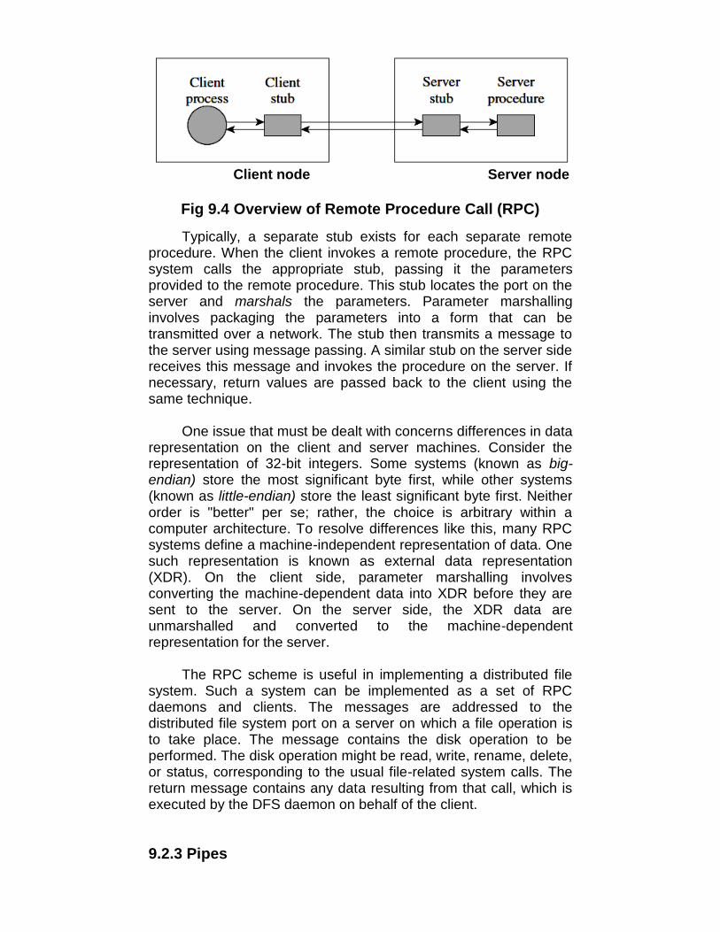
Client node Server node
Fig 9.4 Overview of Remote Procedure Call (RPC)
Typically, a separate stub exists for each separate remoteprocedure. When the client invokes a remote procedure, the RPCsystem calls the appropriate stub, passing it the parametersprovided to the remote procedure. This stub locates the port on theserver and marshals the parameters. Parameter marshallinginvolves packaging the parameters into a form that can betransmitted over a network. The stub then transmits a message tothe server using message passing. A similar stub on the server sidereceives this message and invokes the procedure on the server. Ifnecessary, return values are passed back to the client using thesame technique.
One issue that must be dealt with concerns differences in datarepresentation on the client and server machines. Consider therepresentation of 32-bit integers. Some systems (known as big-endian) store the most significant byte first, while other systems(known as little-endian) store the least significant byte first. Neitherorder is "better" per se; rather, the choice is arbitrary within acomputer architecture. To resolve differences like this, many RPCsystems define a machine-independent representation of data. Onesuch representation is known as external data representation(XDR). On the client side, parameter marshalling involvesconverting the machine-dependent data into XDR before they aresent to the server. On the server side, the XDR data areunmarshalled and converted to the machine-dependentrepresentation for the server.
The RPC scheme is useful in implementing a distributed filesystem. Such a system can be implemented as a set of RPCdaemons and clients. The messages are addressed to thedistributed file system port on a server on which a file operation isto take place. The message contains the disk operation to beperformed. The disk operation might be read, write, rename, delete,or status, corresponding to the usual file-related system calls. Thereturn message contains any data resulting from that call, which isexecuted by the DFS daemon on behalf of the client.
9.2.3 Pipes

A pipe acts as a conduit allowing two processes tocommunicate. Pipes were one of the first IPC mechanisms in earlyUNIX systems and typically provide one of the simpler ways forprocesses to communicate with one another. Two common types ofpipes used on both UNIX and Windows systems are ordinary pipesand named pipes.
Ordinary pipes allow two processes to communicate instandard producer-consumer fashion; the producer writes to oneend of the (the write-end) and the consumer reads from the otherend (the read-end).
In Named pipes, communication can be bidirectional, and noparent-child relationship is required. Once a named pipe isestablished, several processes can use it for communication. Infact, in a typical scenario, a named pipe has several writers.Additionally, named pipes continue to exist after communicatingprocesses have finished. Both UNIX and Windows systems supportnamed pipes, although the details of implementation vary greatly.Named pipes are referred to as FIFOs in UNIX systems. On aWindows systems full-duplex communication is allowed, and thecommunicating processes may reside on either the same ordifferent machines. Windows systems allow either byte- ormessage-oriented data.
9.3 THE CRITICAL SELECTION PROBLEM
Consider a system consisting n processes {P0, P1,…..Pn-1}.Each process has a segment of code, called a critical section, inwhich the process may be changing common variables, updating atable, writing a file, and so on. The important feature of the systemis that, when one process is executing in its critical section, noother process is to be allowed to execute in its critical section.
Thus, the execution of the critical section by the processes ismutually exclusive in time. The critical-section problem is to designa protocol that the processes can use to cooperate. Each processmust request permission to enter its critical section. The section ofcode implementing this request is the entry section. The criticalsection may be followed by an exit section. The remaining code isthe remainder section.
do {
entry section

critical section
remainder section} while(1);
Program Fig 9.5 General structure of a typical process PiThe entry section and exit section are enclosed in boxes to
highlight these important segments of code.
A solution to the critical-section problem must satisfy thefollowing three requirements:
Mutual Exclusion:If process Pi is executing in its critical section, then no other
process can be executed in their critical sections.
Progress:If no process is executing in its critical section and some
processes wish to enter their critical sections, then only thoseprocesses that are not executing in their remainder section canparticipate in the decision on which will enter its critical sectionnext, and this selection cannot be postponed indefinitely.
Bounded Waiting:There exists a bound on the number of times that other
processes are allowed to enter their critical sections after a processhas made a request to enter its critical section and before thatrequest is granted.
We assume each process to be executing at a nonzerospeed. However, we can make no assumption concerning therelative speed of the n processes.
The solutions do not rely on any assumption concerning thehardware instructions such as load, store, and test etc. or thenumber of processes that hardware supports.
9.4 PETERSON’S SOLUTION
In 1965, T. Dekker was the first one to device a softwaresolution to mutual exclusion problem. Dekker’s algorithm solves the
exit section

mutual exclusion problem but with a rather complex program. In1981, Peterson discovered a much simpler algorithm for providingmutual exclusion. Thus rendering Dekker’s solution obsolete.
Peterson’s algorithm is shown below. This algorithm consistsof two procedures written in ANSI C.
#include “prototype.h”
#define FALSE 0# define TRUE 1#define N 2 /* Number of processes */
int turn; /* whose turn is it? */int interested [N]; /* all values initially 0 (FALSE) */
void enter_region(int process) /* process: who is entering (0 or1) */{int other; /* number of other process*/
other = 1 – process; /* the opposite of process*/interested [process] = TRUE /* show that you areinterested */turn = process; /* set flag */while (turn==process && interested[other]==TRUE) /* nullstatement */ ;}
void leave_region(int process) /* process: who is leaving (0 or 1)*/{interested process = FALSE; /*indicate departure fromcritical region */
Peterson’s solution for achieving mutual exclusionBefore using the shared variables (i.e., before entering its
critical region), each process calls enter_region with its ownprocess number, 0 and 1, as parameter. This call will cause it towait, if need be, until it is safe to enter. After it has finished with thevariables, the process calls leave_region to indicate that it is doneand to allow the other process to enter, if it so desires.
Initially neither process is in its critical region. Now process 0calls enter_region. It indicates its interest by setting its arrayelement, and sets turn to 0. Since process1 is not interested,enter_region returns immediately. If process1 now callsenter_region, it will hang there until interested [0] goes to FALSE,an event that only happens when process 0 calls leave_region.

Now consider the case that both processes call enter_regionalmost simultaneously. Both will store their process number in turn.Whichever store is done last is the one that counts; the first one islost. Suppose process 1 stores last, so turn is 1. When bothprocesses come to the while statement, process 1 executes its zerotimes, and enters its critical region. Process 0 loops and does notenter its critical region.
9.5 SEMAPHORES
Definition:
Semaphore is a variable that has an integer value upon whichthe following three operations are defined:
1) A semaphore may be initialized to a non-negative value.2) The wait operation decrements the semaphore value. If the
value becomes negative, then the process executing the wait isblocked.
3) The signal operation increments the semaphore value. If thevalue is not positive, then a process blocked by a-wait operationis unblocked.
Concept of operation:
Two or more processes can cooperate by means of simplesignals, such that the process can be forced to stop at a specifiedplace until it has received a specific signal. For signaling, specialvariables called semaphores, a process executes the primitivewait(s); if the corresponding signal has not yet been transmitted,the process is suspended until the transmission takes place.
The wait and signal primitives are assumed to be atomic; thatis, they cannot be interrupted and each routine can be treated asan indivisible step.
Type semaphore =recordCount : integer;Queue : list of processEnd;
var s : semaphore;wait (s) :
s.count := s.count – 1;

if s.count < 0then begin
place this process in s . queue;block this processend;
signal (s) :s.count: = s.count + 1;if s.count ≤ 0
then beginremove a process P from S.queue;
place process P on ready listend;
Program Figure 9.6 Definition code for semaphores
Implementing mutual Exclusion semaphores:program mutualexclusion;const n = …; (*number of processes*);var s:semaphore (:=1);procedure P (I : integer);begin
repeatwait (s);<critical section>;signal (s);<remainder>forever
endbegin (*main program*)
parbeginP(1);P(2);…P(n)
parendend.Program Figure 9.7 Mutual Exclusion Using Semaphores
Figure shows a straightforward solution to the mutualexclusion problem by semaphores.
The semaphore is initialized to 1. Thus, the first process thatexecutes a signal will be able to immediately enter the criticalsection, setting the value of s to 0. Another process attempting toenter the critical section will find it busy and will be blocked settingthe value of s to – 1. Any number of processes may attempt toenter the section will find it busy and will be blocked. Any number ofprocesses may attempt entry; each such unsuccessful attempt

results in a further decrement of the value of s. When the processthat initially entered its critical section leaves, s is incremented andone of the blocked processes associated with the semaphore is putin a ready state. When it is next scheduled by the operating system,it may enter the critical section.
Instead of using an ordinary semaphores we can use a binarysemaphores which is defined as in figure below:
A Binary semaphore may take on only value 0 and 1.
type semaphore = recordvalue: (0, 1);queue:list of processend;
var s : semaphore;wait B(s) :
if s.value = 1thens.value = 0
else beginplace this process in s.queue;block this process
end;signal B (s) :
if s. count ≤ 0then
if s. value : = 1else begin
remove a process P from s.queue;place process P on ready list
end;Program Figure 9.8 Definition of Binary SemaphorePrimitives
9.6 LET US SUM UP
• A socket is defined as an endpoint for communication
• The RPC was designed as a way to abstract the procedure-callmechanism for use between systems with network connections.
• A port is simply a number included at the start of a messagepacket.
• When the client invokes a remote procedure, the RPC systemcalls the appropriate stub, passing it the parameters provided tothe remote procedure
• A pipe acts as a conduit allowing two processes tocommunicate.
• Two common types of pipes used on both UNIX and Windowssystems are ordinary pipes and named pipes
• The critical-section problem is to design a protocol that theprocesses can use to cooperate
• In 1965, T. Dekker was the first one to device a softwaresolution to mutual exclusion problem
• In 1981, Peterson discovered a much simpler algorithm forproviding mutual exclusion
• Semaphore is a variable that has an integer value upon whichthe following three operations are defined:
1. A semaphore may be initialized to a non-negative value.2. The wait operation decrements the semaphore value. If the
value becomes negative, then the process executing the waitis blocked.
3. The signal operation increments the semaphore value. If thevalue is not positive, then a process blocked by a-waitoperation is unblocked.
9.7 UNIT END QUESTIONS
1. Define : (a) Socket (b) Pipe (c) Semaphore2. What is RPC?3. Discuss in detail the Critical-Section Problem.4. Write a brief note on Peterson’s solution.5. Describe the architecture of semaphore with the help of
program figures.

10
MAIN MEMORY
Unit Structure10.0 Objectives10.1 Introduction10.2 Memory Management Without Swapping / Paging
10.2.1 Dynamic Loading10.2.2 Dynamic Linking10.2.3 Overlays10.2.4 Logical Versus Physical Address Space
10.3 Swapping10.4 Contiguous Memory Allocation
10.4.1 Single-Partition Allocation10.4.2 Multiple-Partition Allocation10.4.3 External And Internal Fragmentation
10.5 Paging10.6 Segmentation10.7 Let us sum up10.8 Unit End Questions
10.0 OBJECTIVES
After reading this unit you will be able to:• Manage memory with/without swapping and paging• Study various memory allocation techniques• Define paging• Define Segmentation
10.1 INTRODUCTION
Memory is central to the operation of a modern computersystem. Memory is a large array of words or bytes, each with itsown address.
A program resides on a disk as a binary executable file. Theprogram must be brought into memory and placed within a processfor it to be executed Depending on the memory management in use

the process may be moved between disk and memory during itsexecution. The collection of processes on the disk that are waitingto be brought into memory for execution forms the input queue. i.e.selected one of the process in the input queue and to load thatprocess into memory.
The binding of instructions and data to memory addresses canbe done at any step along the way:• Compile time: If it is known at compile time where the process willreside in memory, then absolute code can be generated.• Load time: If it is not known at compile time where the process willreside in memory, then the compiler must generate re-locatablecode.• Execution time: If the process can be moved during its executionfrom one memory segment to another, then binding must bedelayed until run time.
Fig 10.1 BINDING OF INSTRUCTIONS10.2 MEMORY MANAGEMENT WITHOUT SWAPPING
OR PAGING

10.2.1 DYNAMIC LOADINGBetter memory-space utilization can be done by dynamic
loading. With dynamic loading, a routine is not loaded until it iscalled. All routines are kept on disk in a re-locatable load format.The main program is loaded into memory and is executed. Theadvantage of dynamic loading is that an unused routine is neverloaded.
10.2.2 DYNAMIC LINKINGMost operating systems support only static linking, in which
system language libraries are treated like any other object moduleand are combined by the leader into the binary program image. Theconcept of dynamic linking is similar to that of dynamic loading.Rather than loading being postponed until execution time, linking ispostponed. This feature is usually used with system libraries, suchas language subroutine libraries. With dynamic linking, a stub isincluded in the image for each library-routine reference. This stub isa small piece of code that indicates how to locate the appropriatememory-resident library routing.
10.2.3 OVERLAYSThe entire program and data of a process must be in physical
memory for the process to execute. The size of a process is limitedto the size of physical memory. So that a process can be largerthan the amount of memory allocated to it, a technique calledoverlays is sometimes used. The idea of overlays is to keep inmemory only those instructions and data that are needed at anygiven time. When other instructions are needed, they are loadedinto space that was occupied previously by instructions that are nolonger needed.
Example, consider a two-pass assembler. During pass 1, itconstructs a symbol table; then, during pass 2, it generatesmachine-language code. We may be able to partition such anassembler into pass 1 code, pass 2 code, the symbol table, andcommon support routines used by both pass 1 and pass 2.
Let us considerPass1 70KPass 2 80KSymbol table 20KCommon routines 30K

FIG 10.2 OVERLAYS
To load everything at once, we would require 200K ofmemory. If only 150K is available, we cannot run our process. Butpass 1 and pass 2 do not need to be in memory at the same time.We thus define two overlays: Overlay A is the symbol table,common routines, and pass 1, and overlay B is the symbol table,common routines, and pass 2.
We add an overlay driver (10K) and start with overlay A inmemory. When we finish pass 1, we jump to the overlay driver,which reads overlay B into memory, overwriting overlay A, and thentransfers control to pass 2. Overlay A needs only 120K, whereasoverlay B needs 130K.
As in dynamic loading, overlays do not require any specialsupport from the operating system.
10.2.4 LOGICAL VERSUS PHYSICAL ADDRESS SPACEAn address generated by the CPU is commonly referred to as
a logical address, whereas an address seen by the memory unit iscommonly referred to as a physical address.
The compile-time and load-time address-binding schemesresult in an environment where the logical and physical addressesare the same. The execution-time address-binding scheme resultsin an environment where the logical and physical addresses differ,in this case, we usually refer to the logical address as a virtualaddress. The set of all logical addresses generated by a program isreferred to as a logical address space; the set of all physicaladdresses corresponding to these logical addresses is referred toas a physical address space.

FIG 10.3 DYNAMIC RELOCATION USING RELOCATIONREGISTER
The run-time mapping from virtual to physical addresses isdone by the memory-management unit (MMU), which is a hardwaredevice.
The base register is called a relocation register. The value inthe relocation register is added to every address generated by auser process at the time it is sent to memory. For example, if thebase is at 13000, then an attempt by the user to address location 0dynamically relocated to location 13,000; an access to location 347is mapped to location 13347. The MS-DOS operating systemrunning on the Intel 80x86 family of processors uses four relocationregisters when loading and running processes.
The user program never sees the real physical addresses.The program can create a pointer to location 347 store it memory,manipulate it, compare it to other addresses — all as the number347.
The user program deals with logical addresses. The memory-mapping hardware converts logical addresses into physicaladdresses.
Logical addresses (in the range 0 to max) and physicaladdresses (in the range R + 0 to R + max for a base value R). Theuser generates only logical addresses.
The concept of a logical address space that is bound to aseparate physical address space is central to proper memorymanagement.10.3 SWAPPING

A process can be swapped temporarily out of memory to abacking store, and then brought back into memory for continuedexecution. Assume a multiprogramming environment with a roundrobin CPU-scheduling algorithm. When a quantum expires, thememory manager will start to swap out the process that justfinished, and to swap in another process to the memory space thathas been freed. When each process finishes its quantum, it will beswapped with another process.
FIG 10.4 SWAPPING OF TWO PROCESSES USING ADISK AND A BACKING STORE
A variant of this swapping policy is used for priority-basedscheduling algorithms. If a higher-priority process arrives and wantsservice, the memory manager can swap out the lower-priorityprocess so that it can load and execute the higher-priority process.When the higher priority process finishes, the lower-priority processcan be swapped back in and continued. This variant of swapping issometimes called rollout, roll in.
A process swapped out will be swapped back into the samememory space that it occupies previously. If binding is done atassembly or load time, then the process cannot be moved todifferent location. If execution-time binding is being used, then it ispossible to swap a process into a different memory space.
Swapping requires a backing store. The backing store iscommonly a fast disk. It is large enough to accommodate copies ofall memory images for all users. The system maintains a readyqueue consisting of all processes whose memory images are onthe backing store or in memory and are ready to run.

The context-switch time in such a swapping system is fairlyhigh. Let us assume that the user process is of size 100K and thebacking store is a standard hard disk with transfer rate of 1megabyte per second. The actual transfer of the 100K process to orfrom memory takes
100K/ 1000K per second =1/10 second = 100 milliseconds
10.4 CONTIGUOUS MEMORY ALLOCATION
The main memory must accommodate both the operatingsystem and the various user processes. The memory is usuallydivided into two partitions, one for the resident operating system,and one for the user processes. To place the operating system inlow memory, we shall discuss only me situation where theoperating system resides in low memory. The development of theother situation is similar. Common Operating System is placed inlow memory.
10.4.1 SINGLE-PARTITION ALLOCATION
If the operating system is residing in low memory, and theuser processes are executing in high memory. And operating-system code and data are protected from changes by the userprocesses. We also need protect the user processes from oneanother. We can provide this 2 protection by using a relocationregisters.
The relocation register contains the value of the smallestphysical address; the limit register contains the range of logicaladdresses (for example, relocation = 100,040 and limit =74,600).With relocation and limit registers, each logical address must beless than the limit register; the MMU maps the logical addressdynamically by adding the value in the relocation register. Thismapped address is sent to memory.
The relocation-register scheme provides an effective way toallow the operating-system size to change dynamically.

Fig 10.5 HARDWARE SUPPORT FOR RELOCATION ANDLIMIT REGISTERS
10.4.2 MULTIPLE-PARTITION ALLOCATION
One of the simplest schemes for memory allocation is todivide memory into a number of fixed-sized partitions. Eachpartition may contain exactly one process. Thus, the degree ofmultiprogramming is bound of partitions. When a partition is free, aprocess is selected from the input queue and is loaded into the freepartition. When the process terminates, the partition becomesavailable for another process.
The operating system keeps a table indicating which parts ofmemory are available and which are occupied. Initially, all memoryis available for user processes, and is considered as one largeblock, of available memory, a hole. When a process arrives andneeds memory, operating system forms a hole large enough for thisprocess.
When a process arrives and needs memory, we search thisset for a hole that is large enough for this process. If the hole is toolarge, it is split into two: One part is allocated to the arrivingprocess; the other is returned to the set of holes. When a processterminates, it releases its block of memory, which is then placedback in the set of holes. If the new hole is adjacent to other holes,we merge these adjacent holes to form one larger hole.
This procedure is a particular instance of the general dynamicstorage-allocation problem, which is how to satisfy a request of sizen from a list of free holes. There are many solutions to this problem.The set of holes is searched to determine which hole is best toallocate, first-fit, best-fit, and worst-fit are the most commonstrategies used to select a free hole from the set of available holes.
First-fit:Allocate the first hole that is big enough. Searching can start
either at the beginning of the set of holes or where the previousfirst-fit search ended. We can stop searching as soon as we find afree hole that is large enough.

Best-fit:Allocate the smallest hole that is big enough. We must search
the entire list, unless the list is kept ordered by size. This strategy-produces the smallest leftover hole.
Worst-fit:Allocate the largest hole. Again, we must search the entire list
unless it is sorted by size. This strategy produces the largestleftover hole which may be more useful than the smaller leftoverhole from a best-t approach.
10.4.3 EXTERNAL AND INTERNAL FRAGMENTATIONAs processes are loaded and removed from memory, the free
memory space is broken into little pieces. External fragmentationexists when enough to the memory space exists to satisfy arequest, but it is not contiguous; storage is fragmented into a largenumber of small holes. Depending on the total amount of memorystorage and the average process size, external fragmentation maybe either a minor or a major problem. Given N allocated blocks,another 0.5N blocks will be lost due to fragmentation. That is, one-third of memory may be unusable. This property is known as the50-percent rule.
Internal fragmentation – memory that is internal to partition,but is not being used.
10.5 PAGING
External fragmentation is avoided by using paging. Physicalmemory is broken into blocks of the same size called pages. Whena process is to be executed, its pages are loaded into any availablememory frames. Every address generated by the CPU is dividedinto any two parts: a page number (p) and a page offset (d). Thepage number is used as an index into a page table. The page tablecontains the base address of each page in physical memory. Thisbase address is combined with the gage offset to define thephysical memory address that is sent to the memory unit.

Fig 10.6 Paging Hardware
The page size like is defined by the hardware. The size of apage is typically a power of 2 varying between 512 bytes and 8192bytes per page, depending on the computer architecture. Theselection of a power of 2 as a page size makes the translation of alogical address space is 2m, and a page size is 2n addressing units(bytes or words), then the high order m-n bits of a logical addressdesignate the page number, and the n low-order bits designate thepage offset. Thus, the logical address is as follows:
page number page offsetp dm-n n
where p is an index into the page table and d is thedisplacement within page.
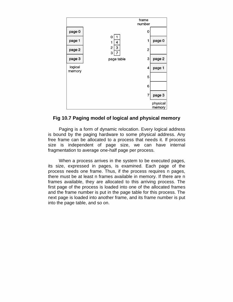
Fig 10.7 Paging model of logical and physical memory
Paging is a form of dynamic relocation. Every logical addressis bound by the paging hardware to some physical address. Anyfree frame can be allocated to a process that needs it. If processsize is independent of page size, we can have internalfragmentation to average one-half page per process.
When a process arrives in the system to be executed pages,its size, expressed in pages, is examined. Each page of theprocess needs one frame. Thus, if the process requires n pages,there must be at least n frames available in memory. If there are nframes available, they are allocated to this arriving process. Thefirst page of the process is loaded into one of the allocated framesand the frame number is put in the page table for this process. Thenext page is loaded into another frame, and its frame number is putinto the page table, and so on.
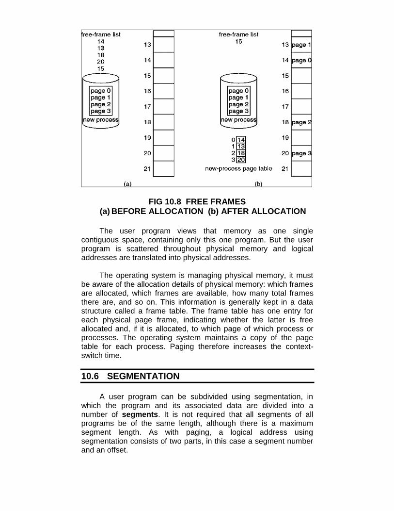
FIG 10.8 FREE FRAMES(a) BEFORE ALLOCATION (b) AFTER ALLOCATION
The user program views that memory as one singlecontiguous space, containing only this one program. But the userprogram is scattered throughout physical memory and logicaladdresses are translated into physical addresses.
The operating system is managing physical memory, it mustbe aware of the allocation details of physical memory: which framesare allocated, which frames are available, how many total framesthere are, and so on. This information is generally kept in a datastructure called a frame table. The frame table has one entry foreach physical page frame, indicating whether the latter is freeallocated and, if it is allocated, to which page of which process orprocesses. The operating system maintains a copy of the pagetable for each process. Paging therefore increases the context-switch time.
10.6 SEGMENTATION
A user program can be subdivided using segmentation, inwhich the program and its associated data are divided into anumber of segments. It is not required that all segments of allprograms be of the same length, although there is a maximumsegment length. As with paging, a logical address usingsegmentation consists of two parts, in this case a segment numberand an offset.

Fig 10.9 USER’S VIEW OF A PROGRAM
Because of the use of unequal-size segments, segmentationis similar to dynamic partitioning. In segmentation, a program mayoccupy more than one partition, and these partitions need not becontiguous. Segmentation eliminates internal fragmentation but,like dynamic partitioning, it suffers from external fragmentation.However, because a process is broken into a number of smallerpieces, the external fragmentation should less. Whereas paging isinvisible to the programmer, segmentation usually visible and isprovided as a convenience for organizing programs and data.
Another consequence of unequal-size segments is that thereis no simple relationship between logical addresses and physicaladdresses. Segmentation scheme would make use of a segmenttable for each process and a list of free blocks of main memory.Each segment table entry would have to, as in paging, give thestarting address in main memory of the corresponding segment.The entry should also provide the length the segment, to assurethat invalid addresses are not used. When a process enters theRunning state, the address of its segment table is loaded into aspecial register used by the memory-management hardware.
Consider an address of n + m bits, where the leftmost n bitsare the segment number and the rightmost m bits are the offset.The following steps are needed for address translation:
• Extract the segment number as the leftmost n bits of the logicaladdress.

• Use the segment number as an index into the process segmenttable to find the starting physical address of the segment.
• Compare the offset, expressed in the rightmost m bits, to thelength of the segment. If the offset is greater than or equal to thelength, the address is invalid.
• The desired physical address is the sum of the starting physicaladdress of the segment plus the offset.
Segmentation and paging can be combined to have a good result.
10.7 LET US SUM UP
• This stub is a small piece of code that indicates how to locatethe appropriate memory-resident library routing
• The execution-time address-binding scheme results in anenvironment where the logical and physical addresses differ
• The base register is called a relocation register.
• Every address generated by the CPU is divided into any twoparts: a page number (p) and a page offset (d)
• The operating system maintains a copy of the page table foreach process
• A user program can be subdivided using segmentation, in whichthe program and its associated data are divided into a numberof segments
10.8 UNIT END QUESTIONS
1. What is dynamic linking?2. Describe overlays in brief.3. What is the difference between single-partition allocation and
multiple-partition allocation?4. Write short notes on :
a. Pagingb. Segmentation

11
VIRTUAL MEMORY
Unit Structure11.0 Objectives11.1 Introduction11.2 Demand Paging11.3 Page Replacement Algorithms
11.3.1 Fifo Algorithm11.3.2 Optimal Algorithm11.3.3 Lru Algorithm11.3.4 Lru Approximation Algorithms11.3.5 Page Buffering Algorithm
11.4 Modeling Paging Algorithms11.4.1 Working-Set Model
11.5 Design Issues for Paging System11.5.1 Prepaging11.5.2 Page Size11.5.3 Program Structure11.5.4 I/O Interlock
11.6 Let Us Sum Up11.7 Unit End Questions
11.0 OBJECTIVES
After reading this unit you will be able to:• To describe the benefits of a virtual memory system• To explain the concepts of demand paging & page-replacement
algorithms, and allocation of page frames.• To discuss the principle of the working-set model
11.1 INTRODUCTION
Virtual memory is a technique that allows the execution ofprocess that may not be completely in memory. The main visibleadvantage of this scheme is that programs can be larger thanphysical memory. Virtual memory is the separation of user logicalmemory from physical memory. This separation allows an

extremely large virtual memory to be provided for programmerswhen only a smaller physical memory is available.
Fig 11.1 Virtual memory is larger than physicalmemory
Virtual memory is commonly implemented by demand paging.It can also be implemented in a segmentation system. Demandsegmentation can also be used to provide virtual memory.
11.2 DEMAND PAGING
A demand paging is similar to a paging system with swapping.When we want to execute a process, we swap it into memory.Rather than swapping the entire process into memory. When aprocess is to be swapped in, the pager guesses which pages willbe used before the process is swapped out again Instead ofswapping in a whole process, the pager brings only thosenecessary pages into memory. Thus, it avoids reading into memorypages that will not be used in anyway, decreasing the swap timeand the amount of physical memory needed.

Fig 11.2 Transfer of a paged memory to contiguousdisk space
Hardware support is required to distinguish between thosepages that are in memory and those pages that are on the diskusing the valid-invalid bit scheme. Where valid and invalid pagescan be checked checking the bit and marking a page will have noeffect if the process never attempts to access the pages. While theprocess executes and accesses pages that are memory resident,execution proceeds normally. Access to a page marked invalidcauses a page-fault trap. This trap is the result of the operatingsystem's failure to bring the desired page into memory. But pagefault can be handled as following:

Fig 11.3 Steps in handling a page fault
1. Check an internal table for this process to determine whether thereference was a valid or invalid memory access.
2, If the reference was invalid, terminate the process. If it was valid,but not yet brought in that page, we now page in the latter
3. Find a free frame4. Schedule a disk operation to read the desired page into the
newly allocated frame.5. When the disk read is complete, modify the internal table kept
with the process and the page table to indicate that the page isnow in memory.
6. Restart the instruction that was interrupted by the illegal addresstrap. The process can now access the page as though it hadalways been memory.
Therefore, the operating system reads the desired page intomemory and restarts the process as though the page had alwaysbeen in memory. The page replacement is used to make the framefree if they are not in used. If no frame is free then other process iscalled in.
11.3 PAGE REPLACEMENT ALGORITHMS
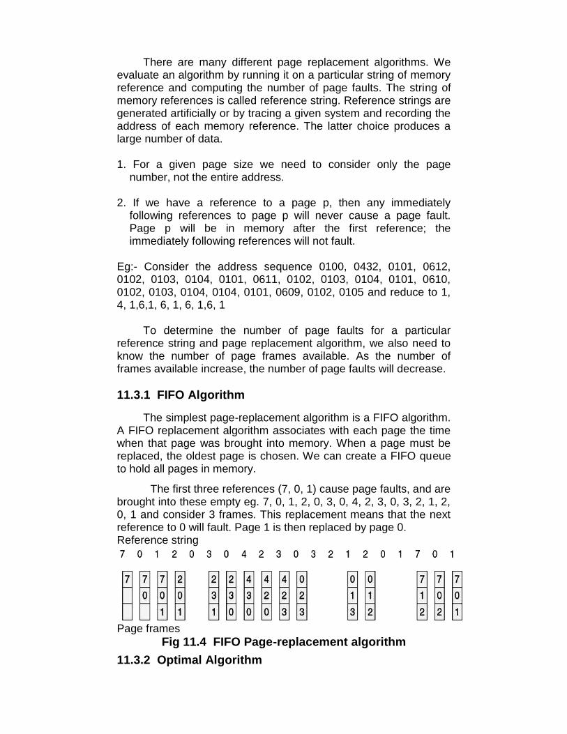
There are many different page replacement algorithms. Weevaluate an algorithm by running it on a particular string of memoryreference and computing the number of page faults. The string ofmemory references is called reference string. Reference strings aregenerated artificially or by tracing a given system and recording theaddress of each memory reference. The latter choice produces alarge number of data.
1. For a given page size we need to consider only the pagenumber, not the entire address.
2. If we have a reference to a page p, then any immediatelyfollowing references to page p will never cause a page fault.Page p will be in memory after the first reference; theimmediately following references will not fault.
Eg:- Consider the address sequence 0100, 0432, 0101, 0612,0102, 0103, 0104, 0101, 0611, 0102, 0103, 0104, 0101, 0610,0102, 0103, 0104, 0104, 0101, 0609, 0102, 0105 and reduce to 1,4, 1,6,1, 6, 1, 6, 1,6, 1
To determine the number of page faults for a particularreference string and page replacement algorithm, we also need toknow the number of page frames available. As the number offrames available increase, the number of page faults will decrease.
11.3.1 FIFO Algorithm
The simplest page-replacement algorithm is a FIFO algorithm.A FIFO replacement algorithm associates with each page the timewhen that page was brought into memory. When a page must bereplaced, the oldest page is chosen. We can create a FIFO queueto hold all pages in memory.
The first three references (7, 0, 1) cause page faults, and arebrought into these empty eg. 7, 0, 1, 2, 0, 3, 0, 4, 2, 3, 0, 3, 2, 1, 2,0, 1 and consider 3 frames. This replacement means that the nextreference to 0 will fault. Page 1 is then replaced by page 0.Reference string
Page framesFig 11.4 FIFO Page-replacement algorithm
11.3.2 Optimal Algorithm
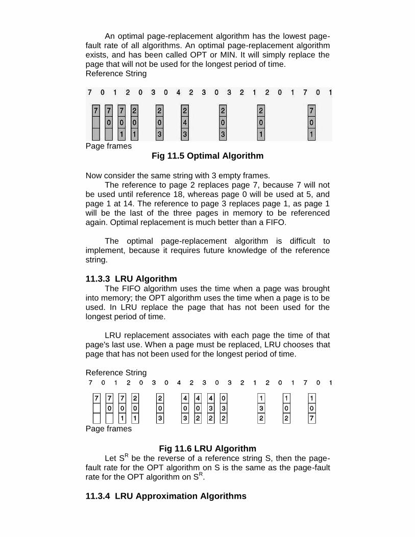
An optimal page-replacement algorithm has the lowest page-fault rate of all algorithms. An optimal page-replacement algorithmexists, and has been called OPT or MIN. It will simply replace thepage that will not be used for the longest period of time.Reference String
Page framesFig 11.5 Optimal Algorithm
Now consider the same string with 3 empty frames.The reference to page 2 replaces page 7, because 7 will not
be used until reference 18, whereas page 0 will be used at 5, andpage 1 at 14. The reference to page 3 replaces page 1, as page 1will be the last of the three pages in memory to be referencedagain. Optimal replacement is much better than a FIFO.
The optimal page-replacement algorithm is difficult toimplement, because it requires future knowledge of the referencestring.
11.3.3 LRU AlgorithmThe FIFO algorithm uses the time when a page was brought
into memory; the OPT algorithm uses the time when a page is to beused. In LRU replace the page that has not been used for thelongest period of time.
LRU replacement associates with each page the time of thatpage's last use. When a page must be replaced, LRU chooses thatpage that has not been used for the longest period of time.
Reference String
Page frames
Fig 11.6 LRU AlgorithmLet SR be the reverse of a reference string S, then the page-
fault rate for the OPT algorithm on S is the same as the page-faultrate for the OPT algorithm on SR.
11.3.4 LRU Approximation Algorithms

Some systems provide no hardware support, and other page-replacement algorithm. Many systems provide some help, however,in the form of a reference bit. The reference bit for a page is set, bythe hardware, whenever that page is referenced. Reference bits areassociated with each entry in the page table. Initially, all bits arecleared (to 0) by the operating system. As a user process executes,the bit associated with each page referenced is set (to 1) by thehardware.
(i) Additional-Reference-Bits AlgorithmThe operating system shifts the reference bit for each page
into the high-order or of its 8-bit byte, shifting the other bits right 1bit, discarding the lower order bit. These 8-bit shift registers containthe history of page use for the last eight, time periods. If the shiftregister contains 00000000, then the page has not been used foreight time periods; a page that is used at least once each periodwould have a shift register value 11111111.
(ii) Second-Chance AlgorithmThe basic algorithm of second-chance replacement is a FIFO
replacement algorithm. When a page gets a second chance, itsreference bit is cleared and its arrival e is reset to the current time.
(iii)Enhanced Second-Chance AlgorithmThe second-chance algorithm described above can be
enhanced by considering troth the reference bit and the modify bitas an ordered pair.
1. (0,0) neither recently used nor modified — best page to replace2. (0,1) not recently used but modified — not quite as good,
because the page will need to be written out before replacement3. (1,0) recently used but clean — probably will be used again soon4. (1,1) recently used and codified - probably will be'iTsed aaain,
and write out will be needed before replacing it
(iv) Counting AlgorithmsThere are many other algorithms that can be used for page
replacement.
• LFO Algorithm: The least frequently used (LFU) page-replacement algorithm requires that the page with the smallestcount be replaced. This algorithm suffers from the situation in whicha page is used heavily during the initial phase of a process, butthen is never used again.
• MFU Algorithm: The most frequently used (MFU) page-replacement algorithm is based on the argument that the page withthe smallest count was probably just brought in and has yet to beused.
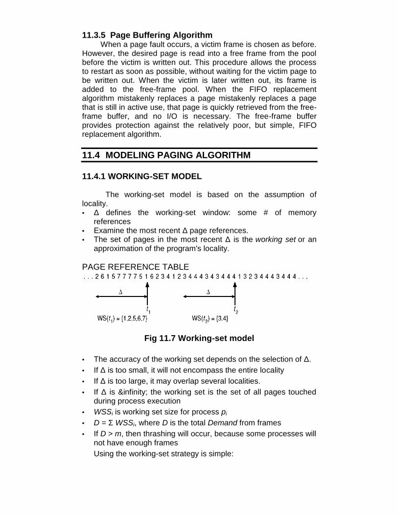
11.3.5 Page Buffering AlgorithmWhen a page fault occurs, a victim frame is chosen as before.
However, the desired page is read into a free frame from the poolbefore the victim is written out. This procedure allows the processto restart as soon as possible, without waiting for the victim page tobe written out. When the victim is later written out, its frame isadded to the free-frame pool. When the FIFO replacementalgorithm mistakenly replaces a page mistakenly replaces a pagethat is still in active use, that page is quickly retrieved from the free-frame buffer, and no I/O is necessary. The free-frame bufferprovides protection against the relatively poor, but simple, FIFOreplacement algorithm.
11.4 MODELING PAGING ALGORITHM
11.4.1 WORKING-SET MODEL
The working-set model is based on the assumption oflocality.• Δ defines the working-set window: some # of memory
references• Examine the most recent Δ page references.• The set of pages in the most recent Δ is the working set or an
approximation of the program's locality.
PAGE REFERENCE TABLE
Fig 11.7 Working-set model
• The accuracy of the working set depends on the selection of Δ.• If Δ is too small, it will not encompass the entire locality• If Δ is too large, it may overlap several localities.• If Δ is &infinity; the working set is the set of all pages touched
during process execution• WSSi is working set size for process pi
• D = Σ WSSi, where D is the total Demand from frames• If D > m, then thrashing will occur, because some processes will
not have enough framesUsing the working-set strategy is simple:

• The OS monitors the working set of each process and allocatesto that working set enough frames to provide it with its working-set size.
• If there are enough extra frames, a new process can beinitiated.
• If the sum of the working set sizes increases, exceeding thetotal number of available frames, the OS selects a process tosuspend.
• The working set strategy prevents thrashing while keeping thedegree of multiprogramming as high as possible and optimizesCPU utilization.
11.5 DESIGN ISSUES FOR PAGING SYSTEMS
11.5.1 PrepagingPrepaging is an attempt to prevent high level of initial
paging. In other words, prepaging is done to reduce the largenumber of page faults that occurs at process startup.Note: Prepage all or some of the pages a process will need, beforethey are referenced.
11.5.2 Page SizePage size selection must take into consideration:
· fragmentation· table size· I/O overhead· locality
11.5.3 Program structure
int [128,128] data;Each row is stored in one page
Program 1:for (j = 0; j <128; j++)for (i = 0; i < 128; i++)
data[i,j] = 0;
128 x 128 = 16,384 page faults
Program 2:for (i = 0; i < 128; i++)
for (j = 0; j < 128; j++)data[i,j] = 0;
128 page faults
11.5.4 I/O Interlock

Pages must sometimes be locked into memory. Consider I/O -Pages that are used for copying a file from a device must be lockedfrom being selected for eviction by a page replacement algorithm.
Fig 11.8 The reason why frames used for 1/0 must be inmemory
11.6 LET US SUM UP
• Virtual memory is the separation of user logical memory fromphysical memory.
• Virtual memory is commonly implemented by demand paging.
• A demand paging is similar to a paging system with swapping.
• The page replacement is used to make the frame free if they arenot in used.
• A FIFO replacement algorithm associates with each page thetime when that page was brought into memory.
• An optimal page-replacement algorithm exists, and has beencalled OPT or MIN.
• LRU replacement associates with each page the time of thatpage's last use.
• When the FIFO replacement algorithm mistakenly replaces apage mistakenly replaces a page that is still in active use, thatpage is quickly retrieved from the free-frame buffer, and no I/Ois necessary.

• The working set strategy prevents thrashing while keeping thedegree of multiprogramming as high as possible and optimizesCPU utilization.
11.7 UNIT END QUESTIONS
1. What is Virtual Memory?2. Describe FIFO Algorithm in detail.3. Write a short note on working-set model.4. Briefly discuss various design issues for paging system.
12
FILE SYSTEM INTERFACEAND IMPLEMENTATION
Unit Structure12.0 Objectives12.1 Introduction12.2 File Concept
12.2.1 File Structure12.2.2 File Management Systems
12.3 File System Mounting12.3.1 Allocation Methods
12.3.1.1 Contiguous Allocation12.3.1.2 Linked Allocation12.3.1.3 Indexed Allocation
12.4 Free Space Management12.4.1 Bit Vector12.4.2 Linked List12.4.3 Grouping12.4.4 Counting
12.5 File Sharing12.5.1 Multiple Users
12.5.2 Remote File Systems12.5.3 Consistency Semantics
12.6 NFS12.7 Let Us Sum Up12.8 Unit End Questions
12.0 OBJECTIVES
After reading this unit you will be able to:• Describe various allocation methods• Manage free space• Study various File sharing systems
12.1 INTRODUCTION
The most important parts of an operating system is the filesystem. The file system provides the resource abstractions typicallyassociated with secondary storage. The file system permits usersto create data collections, called files, with desirable properties,such as the following:
• Long-term existence: Files are stored on disk or othersecondary storage and do not disappear when a user logsoff.
• Sharable between processes: Files have names andcan have associated access permissions that permitcontrolled sharing.
• Structure: Depending on the file system, a file can have aninternal structure that is convenient for particularapplications. In addition, files can be organized intohierarchical or more complex structure to reflect therelationships among files.
Any file system provides not only a means to store dataorganized as files, but a collection of functions that can beperformed on files. Typical operations include the following:
• Create: A new file is defined and positioned within thestructure of files.
• Delete: A file is removed from the file structure anddestroyed.
• Open: An existing file is declared to be "opened" by aprocess, allowing the process to perform functions on thefile.
• Close: The file is closed with respect to a process, so thatthe process no longer may perform functions on the file, untilthe process opens the file again.
• Read: A process reads all or a portion of the data in a file.
• Write: A process updates a file, either by adding new datathat expands the size of the file or by changing the values ofexisting data items in the file.
Typically, a file system maintains a set of attributes associatedwith the file.
12.2 FILE CONCEPTS
12.2.1 FILE STRUCTUREThree terms are used for files
• Field• Record

• DatabaseA field is the basic element of data. An individual field contains a
single value.
A record is a collection of related fields that can be treated as aunit by some application program.
A file is a collection of similar records. The file is treated as asingle entity by users and applications and may be referenced byname. Files have file names and may be created and deleted.Access control restrictions usually apply at the file level.
A database is a collection of related data. Database is designedfor use by a number of different applications. A database maycontain all of the information related to an organization or project,such as a business or a scientific study. The database itselfconsists of one or more types of files. Usually, there is a separatedatabase management system that is independent of the operatingsystem.
12.2.2 FILE MANAGEMENT SYSTEMSA file management system is that set of system software thatprovides services to users and applications in the use of files.Following are the objectives for a file management system.
• To meet the data management needs and requirements ofthe user which include storage of data and the ability toperform the aforementioned operations.
• To guarantee, to the extent possible, that the data in the fileare valid.
• To optimize performance, both from the system point of viewin terms of overall throughput.
• To provide I/O support for a variety of storage device types.
• To minimize or eliminate the potential for lost or destroyeddata.
• To provide a standardized set of I/O interface routines to useprocesses.
• To provide I/O support for multiple users, in the case ofmultiple-user systems.
File System ArchitectureAt the lowest level, device drivers communicate directly with
peripheral devices or their controllers or channels. A device driveris responsible for starting I/O operations on a device andprocessing the completion of an I/O request. For file operations, thetypical devices controlled are disk and tape drives. Device driversare usually considered to be part of the operating system.

The next level is referred to as the basic file system or thephysical I/O level. This is the primary interface with the environmentoutside of the computer system. It deals with blocks of data that areexchanged with disk or tape system.
The basic I/O supervisor is responsible for all file I/O initiationand termination. At this level control structures are maintained thatdeal with device I/O scheduling and file status. The basic 1.0supervisor selects the device on which file I/O is to be performed,based on the particular file selected.
Logical I/O enables users and applications to access records.The level on the file system closest to the user is often termed theaccess method. It provides a standard interface betweenapplications and the file systems device that hold the data. Differentaccess methods reflect different file structures and different ways ofaccessing and processing the data.
The I/O control, consists of device drivers and interrupthandlers to transfer information between the memory and the disksystem. A device driver can be thought of as a translator.
The basic file system needs only to issue generic commandsto the appropriate device driver to read and write physical blocks onthe disk.
File organization and access:The term file organization to refer to the logical structuring of the
records as determined by the way in which they are accessed. Thephysical organization of the file on secondary storage depends onthe blocking strategy and the file allocation strategy. In choosing afile organization.
1. Short access time2. Ease of update3. Economy of storage4. Simple maintenance5. Reliability.
The relative priority of these criteria will depend on theapplications that will use the file.
The file-organization module knows about files and their logicalblocks, as well as physical blocks. By knowing the type of fileallocation used and the location of the file, the file-organizationmodule can translate logical block addresses to physical blockaddresses for the basic file system to transfer. Each file's logicalblocks are numbered from 0 (or 1) through N, whereas the physicalblocks containing the data usually do not match the logicalnumbers, so a translation is needed to locate each block. The file-organization module also includes the free-space manager, which
tracks unallocated and provides these blocks to the file organizationmodule when requested.
The logical file system uses the directory structure to providethe file-organization module with the information the latter needs,given a symbolic file name. The logical file system is alsoresponsible for protection and security.
To create a new file, an application program calls the logical filesystem. The logical file system knows the format of the directorystructures. To create new file, it reads the appropriate directory intomemory, updates it with the new entry, and writes it back to thedisk.
Once, the file is found, the associated information such as size,owner, and data block locations are generally copied into a table inmemory, referred to as the open-file table; consisting of informationabout all the currently opened files.
The first reference to a file (normally an open) causes thedirectory structure to be searched and the directory entry for this fileto be copied into the table of opened files. The index into this tableis returned to the user program, and all further references are madethrough the index rather than with a symbolic name. The namegiven to the index varies. UNIX systems refer to it as a filedescriptor, Windows/NT as a file handle, and other systems as afile control block. Consequently, as long as the file is not closed, allfile operations are done on the open-file table. When the file isclosed by all users that have opened it, the updated file informationis copied back to the disk-based directory structure.
12.3 FILE SYSTEM MOUNTING
As a file must be opened before it is used, a file system mustbe mounted before it can be available to processes on the system.The mount procedure is straight forward. The stem is given thename of the device, and the location within the file structure atwhich to attach the file system (called the mount point).
The operating system verifies that the device contains a validfile system. It does so by asking the device driver to read the devicedirectory and verifying that the directory has the expected format.Finally, the operating system notes in its directory structure that afile system is mounted at the specified mount point. This schemeenables the operating system to traverse its directory structure,switching among file systems as appropriate.
12.3.1 Allocation Methods

The direct-access nature of disks allows us flexibility in theimplementation of files. Three major methods of allocating diskspace are in wide use: contiguous, linked and indexed. Eachmethod has its advantages and disadvantages.
12.3.1.1 Contiguous AllocationThe contiguous allocation method requires each file to occupy
a set of contiguous blocks on the disk. Disk addresses define alinear ordering on the disk. Notice that with this ordering assumingthat only one job is accessing the disk, accessing block b+1 afterblock b normally requires no head movement. When headmovement is needed, it is only one track. Thus, the number of diskseeks required for accessing contiguous allocated files is minimal.
Fig 12.1 Contiguous allocation of disk space
Contiguous allocation of a tile is defined by the disk addressand length (in block units) of the first block. If the file is n blockslong, and starts at a specific location then it occupies blocks b, b +1, b +2,..,b+n-1. The directory entry for each file indicates theaddress of the starting block and the length of the area allocate forthis file.
Accessing a file that has been allocated contiguously is easy.For sequential access, the file system remembers the disk addressof the last block referenced and, when necessary, reads the nextblock. For direct access to block i of a file that starts at block b, wecan immediately access block b+i.
The contiguous disk-space-allocation problem can be seen tobe a particular application of the general dynamic storage-allocationFirst Fit and Best Fit are the most common strategies used to selecta free hole from the set of available holes. Simulations have shown

that both first-fit and best-fit are more efficient than worst-fit in termsof both time and storage utilization. Neither first-fit nor best-fit isclearly best in terms of storage utilization, but first-fit is generallyfaster.
These algorithms suffer from the problem of externalfragmentation. As files are allocated and deleted, the free diskspace is broken into little pieces. External fragmentation existswhenever free space is broken into chunks. It becomes a problemwhen the largest contiguous chunks is insufficient for a request;storage is fragmented into a number of holes, no one of which islarge enough to store the data. Depending on the total amount ofdisk storage and the average file size, external fragmentation maybe either a minor or a major problem.
To prevent loss of significant amounts of disk space toexternal fragmentation, the user had to run repacking routine thatcopied the entire file system onto another floppy disk or onto atape. The original floppy disk was then freed completely, creatingone large contiguous free space. The routine then copied the filesback onto the floppy disk by allocating contiguous space from thisone large hole. This scheme effectively compacts all free space intoone contiguous space, solving the fragmentation problem. The costof this compaction is time. The time cost is particularly severe forlarge hard disks that use contiguous allocation, where compactingall the space may take hours and may be necessary on a weeklybasis. During this down time, normal system operation generallycannot be permitted, so such compaction is avoided at all costs onproduction machines.
A major problem is determining how much space is neededfor a file. When the file is created, the total amount of space it willneed must be found and allocated. The user will normally overestimate the amount of space needed, resulting in considerablewasted space.
12.3.1.2 Linked AllocationLinked allocation solves all problems of contiguous allocation.
With link allocation, each file is a linked list disk blocks; the diskblocks may be scattered anywhere on the disk. This pointer isinitialized to nil (the end-of-list pointer value) to signify an empty file.The size field is also set to 0. A write to the file causes a'free bio tobe found via the free-space management system, and this newblock is the written to, and is linked to the end of the file.
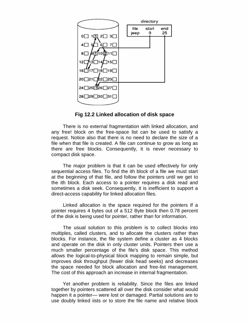
Fig 12.2 Linked allocation of disk space
There is no external fragmentation with linked allocation, andany free! block on the free-space list can be used to satisfy arequest. Notice also that there is no need to declare the size of afile when that file is created. A file can continue to grow as long asthere are free blocks. Consequently, it is never necessary tocompact disk space.
The major problem is that it can be used effectively for onlysequential access files. To find the ith block of a file we must startat the beginning of that file, and follow the pointers until we get tothe ith block. Each access to a pointer requires a disk read andsometimes a disk seek. Consequently, it is inefficient to support adirect-access capability for linked allocation files.
Linked allocation is the space required for the pointers If apointer requires 4 bytes out of a 512 Byte block then 0.78 percentof the disk is being used for pointer, rather than for information.
The usual solution to this problem is to collect blocks intomultiples, called clusters, and to allocate the clusters rather thanblocks. For instance, the file system define a cluster as 4 blocksand operate on the disk in only cluster units. Pointers then use amuch smaller percentage of the file's disk space. This methodallows the logical-to-physical block mapping to remain simple, butimproves disk throughput (fewer disk head seeks) and decreasesthe space needed for block allocation and free-list management.The cost of this approach an increase in internal fragmentation.
Yet another problem is reliability. Since the files are linkedtogether by pointers scattered all over the disk consider what wouldhappen it a pointer— were lost or damaged. Partial solutions are touse doubly linked iists or to store the file name and relative block

number in each block; however, these schemes require even moreoverhead for each file.
An important variation, on the linked allocation method is theuse of a file allocation table (FAT). This simple but efficient methodof disk-space allocation is used by the MS-DOS and OS/2operating systems. A section of disk at the beginning of each-partition is set aside to contain the table. The table has one entryfor each disk block, and is indexed by block number. The FAT isused much as is a linked list. The directory entry contains the blocknumber of the first block of the file. The table entry indexed by thatblock number then contains the block number of the next block inthe file. This chain continues until the last block, which has aspecial end-of-file value -as the table entry. Unused blocks areindicated by a 0 table value. Allocating a new block to a file is asimple matter of finding the first 0-valued table entry, and replacingthe previous end-of-file value with the address of the new block.The 0 is then replaced with the end-of-file value. An illustrativeexample is the FAT structure of for a file consisting of disk blocks217, 618, and 339.
12.3.1.3 Indexed AllocationLinked allocation solves the external-fragmentation and size-
declaration problems of contiguous allocation. The absence of aFAT, linked allocation cannot support efficient direct access, sincethe pointers to the blocks are scattered with the blocks themselvesall over the disk and need to be retrieved in order Indexedallocation solves this problem by bringing all the pointers togetherinto one location: the index block.
Each file has its own index block, which is an array of disk-block addresses. The ith entry in the index block points to the ithblock of the file. The directory contains the address of the indexblock.
When the file is created, all pointers in the index block are setto nil. When the ith block is first written, a block is obtained: fromthe free space manager, and its address- is put in the ith index-block entry.

Fig 12.3 Indexed allocation of disk space
Allocation supports direct access, without suffering fromexternal fragmentation because any free block on he disk maysatisfy a request for more space. Indexed allocation does sufferfrom wasted space. The pointer overhead of the index block isgenerally greater than the pointer overhead of linked allocation.
• Linked scheme. An index block is normally one disk block.Thus, it can be read and written directly by itself.
• Multilevel index. A variant of the linked representation is touse a first-level index block to point to a set of second-levelindex blocks, which in turn point to the file blocks. To access ablock, the operating system uses the first-level index to find asecond-level index block, and that block to find the desired datablock.
12.4 FREE SPACE MANAGEMENT
Since there is only a limited amount of disk space, it isnecessary to reuse the space from deleted files for new files, ifpossible.
12.4.1 BIT VECTORFree-space list is implemented as a bit map or bit vector. Each
block is represented by 1 bit. If the block is free, the bit is 1; if theblock is allocated, the bit is 0. For example consider a disk whereblocks 2, 3, 4, 5, 8,9,10,11,12,13,17, 18, 25, 26, and 27 are free,and the rest of the blocks are allocated. The free-space bit mapwould be
001111001111110001100000011100000 .....The main advantage of this approach is that it is relatively
simple and efficient to find the first free block or n consecutive free

blocks on the disk. The calculation of the block number is (numberof bits per word) x (number of 0-value words) + offset of first 1 bit
12.4.2 LINKED LIST
Another approach is to link together all the free disk blocks,keeping a pointer to the first free block in a special location on thedisk and caching in memory. This first block contains a pointer tothe next free disk block, and so on. Block 2 would contain a pointerto block 3, which would point to block 4, which would point to block5, which would point to block 8, and so on. Usually, the operatingsystem simply needs a free block so that it can allocate that blockto a file, so the first block in the free list is used.
Fig 12.4 Linked free-space list on disk
12.4.3 GROUPING
A modification of the free-list approach is to store theaddresses of n free blocks in the first free block. The first n-1 ofthese blocks are actually free. The importance of thisimplementation is that the addresses of a large number of freeblocks can be found quickly, unlike in the standard linked-listapproach.
12.4.4 COUNTING
Several contiguous blocks may be allocated or freedsimultaneously, particularly when space is allocated with thecontiguous allocation algorithm or through clustering. A list of n freedisk addresses, we can keep the address of the first free block andthe number n of free contiguous blocks that follow the first block A.Each entry in the free-space list then consists of a disk address anda count. Although each entry requires more space than would a

simple disk address, the overall list will be shorter, as long as thecount is generally greater than 1.
12.5 FILE SHARING
Once multiple users are allowed to share files, the challengeis to extend sharing to multiple file systems, including remote filesystems.
12.5.1 MULTIPLE USERS
To implement sharing and protection, the system mustmaintain more file and directory attributes than are needed on asingle-user system. Although many approaches have been taken tomeet this requirement, most system have evolved to use theconcepts of file (or directory) owner (or user) and group. The owneris the user who can change attributes and grant access and whohas the most control over the file. The group attribute defines asubset of users who can share access to the file. For example, theowner of a file on a UNIX system can issue all operations on a file,while members of the file's group can execute one subset of thoseoperations, and all other users can execute another subset ofoperations. Exactly which operations can be executed by groupmembers and other users is definable by the file's owner.
12.5.2 REMOTE FILE SYSTEMS
Remote File system uses networking to allow file systemaccess between systems:• Manually via programs like FTP• Automatically, seamlessly using distributed file systems• Semi automatically via the world wide web
12.5.3 CONSISTENCY SEMANTICS
Consistency semantics represent an important criterion forevaluating any file system that supports file sharing. Thesesemantics specify how multiple users of a system are to access ashared file simultaneously. In particular, they specify whenmodifications of data by one user will be observable by other users.These semantics are typically implemented as code with the filesystem.
12.6 NFS
Network File Systems [NFS] are standard UNIX client-serverfile sharing protocol. Interconnected workstations are viewed as a
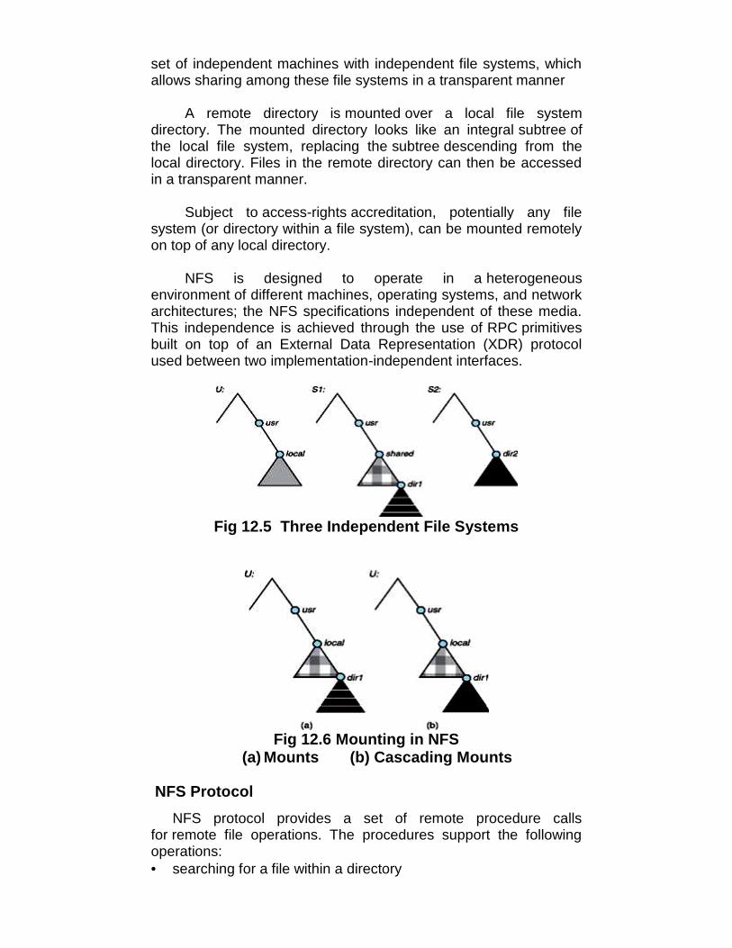
set of independent machines with independent file systems, whichallows sharing among these file systems in a transparent manner
A remote directory is mounted over a local file systemdirectory. The mounted directory looks like an integral subtree ofthe local file system, replacing the subtree descending from thelocal directory. Files in the remote directory can then be accessedin a transparent manner.
Subject to access-rights accreditation, potentially any filesystem (or directory within a file system), can be mounted remotelyon top of any local directory.
NFS is designed to operate in a heterogeneousenvironment of different machines, operating systems, and networkarchitectures; the NFS specifications independent of these media.This independence is achieved through the use of RPC primitivesbuilt on top of an External Data Representation (XDR) protocolused between two implementation-independent interfaces.
Fig 12.5 Three Independent File Systems
Fig 12.6 Mounting in NFS(a) Mounts (b) Cascading Mounts
NFS ProtocolNFS protocol provides a set of remote procedure calls
for remote file operations. The procedures support the followingoperations:• searching for a file within a directory
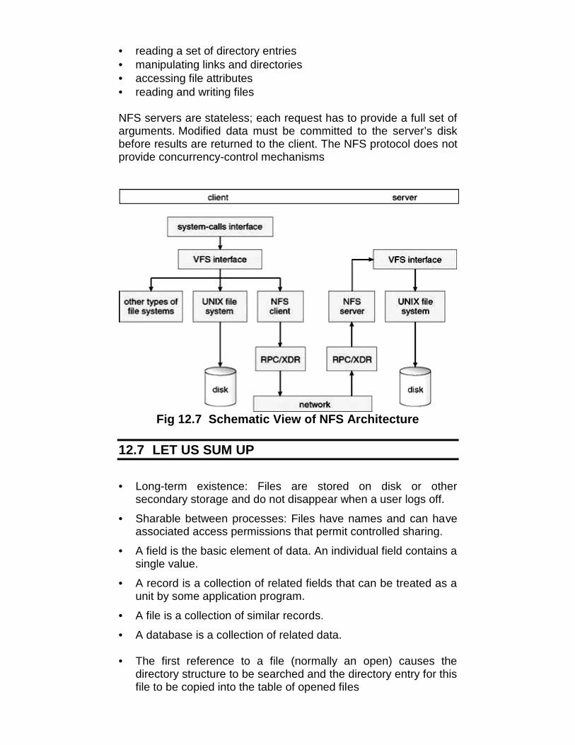
• reading a set of directory entries• manipulating links and directories• accessing file attributes• reading and writing files
NFS servers are stateless; each request has to provide a full set ofarguments. Modified data must be committed to the server’s diskbefore results are returned to the client. The NFS protocol does notprovide concurrency-control mechanisms
Fig 12.7 Schematic View of NFS Architecture
12.7 LET US SUM UP
• Long-term existence: Files are stored on disk or othersecondary storage and do not disappear when a user logs off.
• Sharable between processes: Files have names and can haveassociated access permissions that permit controlled sharing.
• A field is the basic element of data. An individual field contains asingle value.
• A record is a collection of related fields that can be treated as aunit by some application program.
• A file is a collection of similar records.
• A database is a collection of related data.
• The first reference to a file (normally an open) causes thedirectory structure to be searched and the directory entry for thisfile to be copied into the table of opened files

• The contiguous allocation method requires each file to occupy aset of contiguous blocks on the disk
• First Fit and Best Fit are the most common strategies used toselect a free hole from the set of available holes.
• External fragmentation exists whenever free space is brokeninto chunks.
• The owner is the user who can change attributes and grantaccess and who has the most control over the file. The groupattribute defines a subset of users who can share access to thefile.
• Network File Systems [NFS] are standard UNIX client-serverfile sharing protocol.
• NFS servers are stateless; each request has to provide a full setof arguments.
12.8 UNIT END QUESTIONS
1. Define the terms :a. Fieldb. Recordc. Database
2. What are the objectives for a file management system?3. What is File System Mounting? Explain Contiguous Allocation
method in detail.4. What is the difference between Linked Allocation and Indexed
Allocation methods?5. Write a short note Bit Vector.6. What is NFS? What are its protocols?
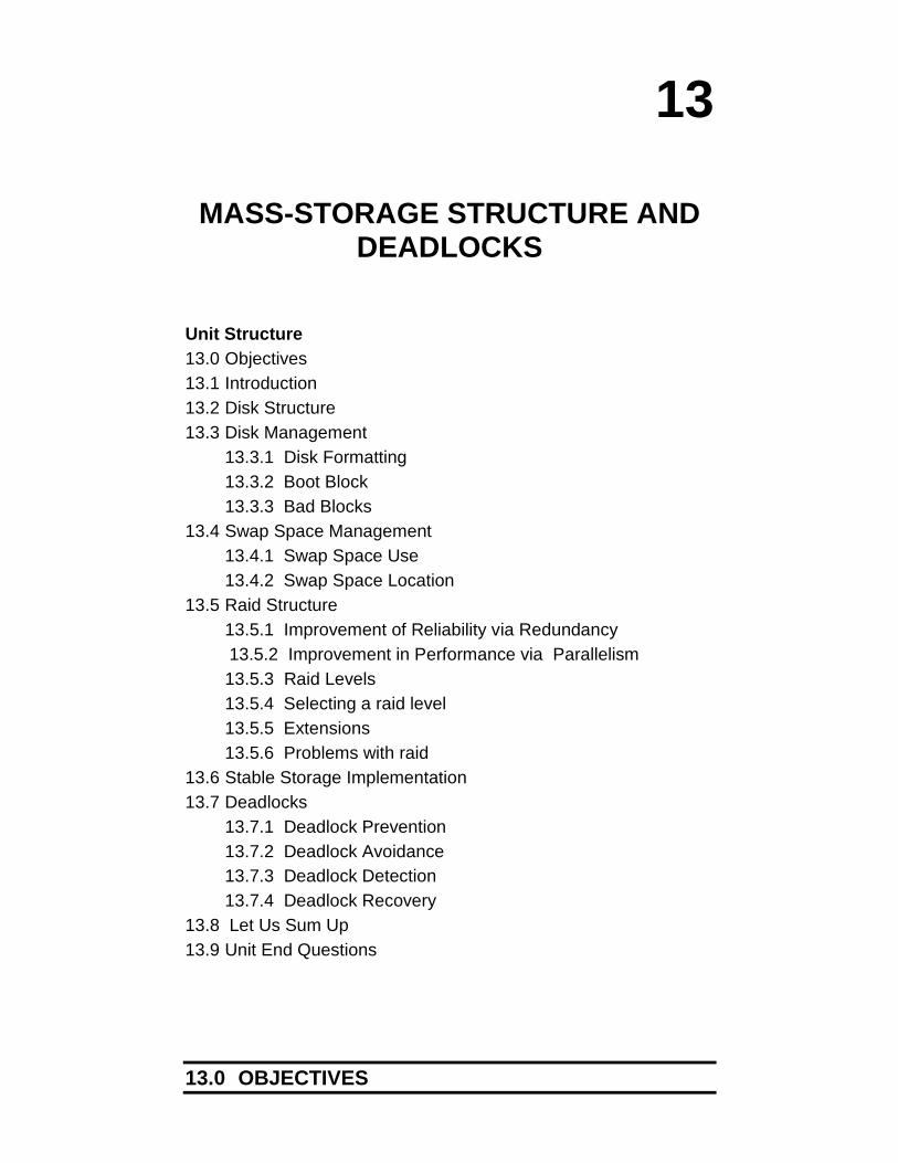
13
MASS-STORAGE STRUCTURE ANDDEADLOCKS
Unit Structure13.0 Objectives13.1 Introduction13.2 Disk Structure13.3 Disk Management
13.3.1 Disk Formatting13.3.2 Boot Block13.3.3 Bad Blocks
13.4 Swap Space Management13.4.1 Swap Space Use13.4.2 Swap Space Location
13.5 Raid Structure13.5.1 Improvement of Reliability via Redundancy
13.5.2 Improvement in Performance via Parallelism13.5.3 Raid Levels13.5.4 Selecting a raid level13.5.5 Extensions13.5.6 Problems with raid
13.6 Stable Storage Implementation13.7 Deadlocks
13.7.1 Deadlock Prevention13.7.2 Deadlock Avoidance13.7.3 Deadlock Detection13.7.4 Deadlock Recovery
13.8 Let Us Sum Up13.9 Unit End Questions
13.0 OBJECTIVES

After reading this unit you will be able to:• Describe boot blocks and bad blocks• Distinguish between various levels of RAID• Define deadlock• Detect, recover, avoid and prevent deadlocks
13.1 INTRODUCTION
In order to get vast amount of storage capacity of severalbytes (trillions and more) in a computer system, a different kind ofstorage system is used. In such type of system, multiple units ofsimilar kinds of storage media are associated together to form achain of mass storage devices. These storage media may includemultiple magnetic tape reels or cartridges, multiple arrays ofmagnetic disks or multiple CD-ROMs as a storage device. We cancategorize mass storage devices into three types:
1. Redundant Array of Inexpensive Disks (RAID)2. Automated Tape Library3. CD-ROM Jukebox
13.2 DISK STRUCTURE
The size of a logical block is usually 512 bytes, although somedisks can be low-level formatted to have a different logical blocksize. The one-dimensional array of logical blocks is mapped ontothe sectors of the disk sequentially. Sector 0 is the first sector of thefirst track on the outermost cylinder.
In practice, it is difficult to perform this translation, for tworeasons. First, most disks have some defective sectors, but themapping hides this by substituting spare sectors from elsewhere onthe disk. Second, the number of sectors per track is not a constanton some drives.
On media that uses constant linear velocity (CLV), the densityof bits per track is uniform. The farther a track is from the center ofthe disk, the greater its length, so the more sectors it can hold. Aswe move from outer zones to inner zones, the number of sectorsper track decreases. Tracks in the outermost zone typically hold 40percent more sectors than do tracks in the innermost zone. Thedrive increases its rotation speed as the head moves from the outerto the inner tracks to keep the same rate of data moving under thehead. This method is used in CD-ROM and DVD-ROM drives.Alternatively, the disk rotation speed can stay constant; in this case,the density of bits decreases from inner tracks to outer tracks tokeep the data rate constant. This method is used in hard disks andis known as constant angular velocity (CAV).

The number of sectors per track has been increasing now-a-days and the outer zone of a disk usually has several hundredsectors per track. Similarly, the number of cylinders per disk hasbeen increasing; large disks have tens of thousands of cylinders.
13.3 DISK MANAGEMENT
13.3.1 DISK FORMATTINGBefore a disk can store data, it must be divided into sectors
that the disk controller can read and write. This process is calledlow-level formatting or physical formatting. Low-level formatting fillsthe disk with a special data structure for each sector. The datastructure for a sector typically consists of a header, a data area(usually 512 bytes in size), and a trailer. The header and trailercontain information used by the disk controller, such as a sectornumber and an error-correcting code (ECC).
The ECC contains enough information, if only a few bits ofdata have been corrupted, to enable the controller to identify whichbits have changed and calculate what their correct values shouldbe. It then reports a recoverable soft error. This formatting enablesthe manufacturer to test the disk and to initialize the mapping fromlogical block numbers to defect-free sectors on the disk.
The second step is logical formatting, or creation of a filesystem. In this step, the operating system stores the initial file-system data structures onto the disk. These data structures mayinclude maps of free and allocated space (a FAT or inodes) and aninitial empty directory.
13.3.1 BOOT BLOCK
The initial bootstrap (stored in ROM for most computers)program initializes all aspects of the system, from CPU registers todevice controllers and the contents of main memory, and thenstarts the operating system by finding the OS Kernel on disk,loading it in memory and jumping to an initial address to begin theOS execution.
The full bootstrap program is stored in the "boot blocks" at afixed location on the disk. A disk that has a boot partition is called aboot disk or system disk. Several major kinds of boot sectors couldbe encountered on IBM PC compatible hard disks, floppy disks andsimilar storage devices:• A Master Boot Record (MBR) is the first sector of a data
storage device that has been partitioned. The MBR sector maycontain code to locate the active partition and invoke its VolumeBoot Record.

• A Volume Boot Record (VBR) is the first sector of a datastorage device that has not been partitioned, or the first sectorof an individual partition on a data storage device that has beenpartitioned. It may contain code to load and invoke an operatingsystem (or other standalone program) installed on that device orwithin that partition.
13.3.1 BAD BLOCKS
A bad sector is a sector on a computer's disk drive or flashmemory that cannot be used due to permanent damage (or an OSinability to successfully access it), such as physical damage to thedisk surface (or sometimes sectors being stuck in a magnetic ordigital state that cannot be reversed) or failed flash memorytransistors. It is usually detected by a disk utility software suchas CHKDSK or SCANDISK on Microsoft systems, or badblocks onUnix-like systems. When found, these programs may mark thesectors unusable (all file systems contain provisions for bad-sectormarks) and the operating system skips them in the future.
More sophisticated disks, such as the SCSI disks used inhigh-end PCs and most workstations and servers, are smarterabout bad-block recovery. The controller maintains a list of badblocks on the disk. The list is initialized during the low-levelformatting at the factory and is updated over the life of the disk.Low-level formatting also sets aside spare sectors not visible to theoperating system. The controller can be told to replace each badsector logically with one of the spare sectors. This scheme isknown as sector-sparing or forwarding.
As an alternative to sector sparing, some controllers can beinstructed to replace a bad block by sector slipping. During a low-level format, defect lists are populated which store which sectorsare bad. The bad sectors are then mapped and a sector slippingalgorithm is utilized. When using sector slipping for bad sectors,disk access time is not largely affected. The drive will just skip overthe sectors and takes the same time as it would have to read thesector. Spare sectors are located on the disk to aid in havingsectors to “slip” other sectors down to, allowing for the preservationof sequential ordering of the data. Accuracy of programs reliant onstatic knowledge of cylinders and block positions will becompromised though.
13.4 SWAP SPACE MANAGEMENT
Swap-space management refers to the process where OSbreaks the physical RAM that is structured with random accessmemory into some pitches of memory called pages. This is themethod in which a single page of memory can be copied to the

preconfigured space on a hard disk. This is called swap space. Thisprocess helps to free up that page of memory. An assessmenthelp can say that these sizes when considered altogether of thephysical memory as well as the swap space can be recognized interms of total virtual memory that is available for the whole system.
13.4.1 SWAP SPACE USE
Systems that implement swapping may use swap space tohold an entire process image including the code and datasegments. Paging systems may simply store pages that have beenpushed out of main memory. The amount of swap space needed ona system can therefore vary from a few megabytes of disk space togigabytes depending on the amow1.t of physical memory theamount of virtual memory it is backing and the way in which thevirtual memory is used.
13.4.2 SWAP SPACE LOCATION
A swap space can reside in one of two places: it can becarved out of the normal file system, or it can be in a separate diskpartition. If the swap space is simply a large file within the filesystem, normal file-system routines can be used to create it, nameit and allocate its space. Alternatively, swap space can be createdin a separate partition. No file system or directory structure isplaced in this space. Rather, a separate swap-space storagemanager is used to allocate and de-allocate the blocks from the rawpartition. This manager uses algorithms optimized for speed ratherthan for storage efficiency, because swap space is accessed muchmore frequently than file systems.
13.5 RAID STRUCTURE
A variety of disk-organization techniques, collectivelycalled redundant arrays of inexpensive disks (RAIDs) arecommonly used to address the performance and reliability issues.In the past, RAIDs composed of small, cheap disks were viewed asa cost-effective alternative to large, expensive disks. Today, RAIDsare used for their higher reliability and higher data-transfer rate,rather than for economic reasons. Hence, the I in RAID now standsfor ``independent'' instead of “inexpensive”.
13.5.1 Improvement of Reliability via RedundancySuppose that the mean time to failure of a single disk is 100000
hours. Then the mean time to failure of some disk in an array of100 disks will be 100000/100 = 1000 hours, or 41.66 days, which isnot long at all. If we store only one copy of the data, then each diskfailure will result in loss of a significant amount of data-and such ahigh rate of data loss is unacceptable.
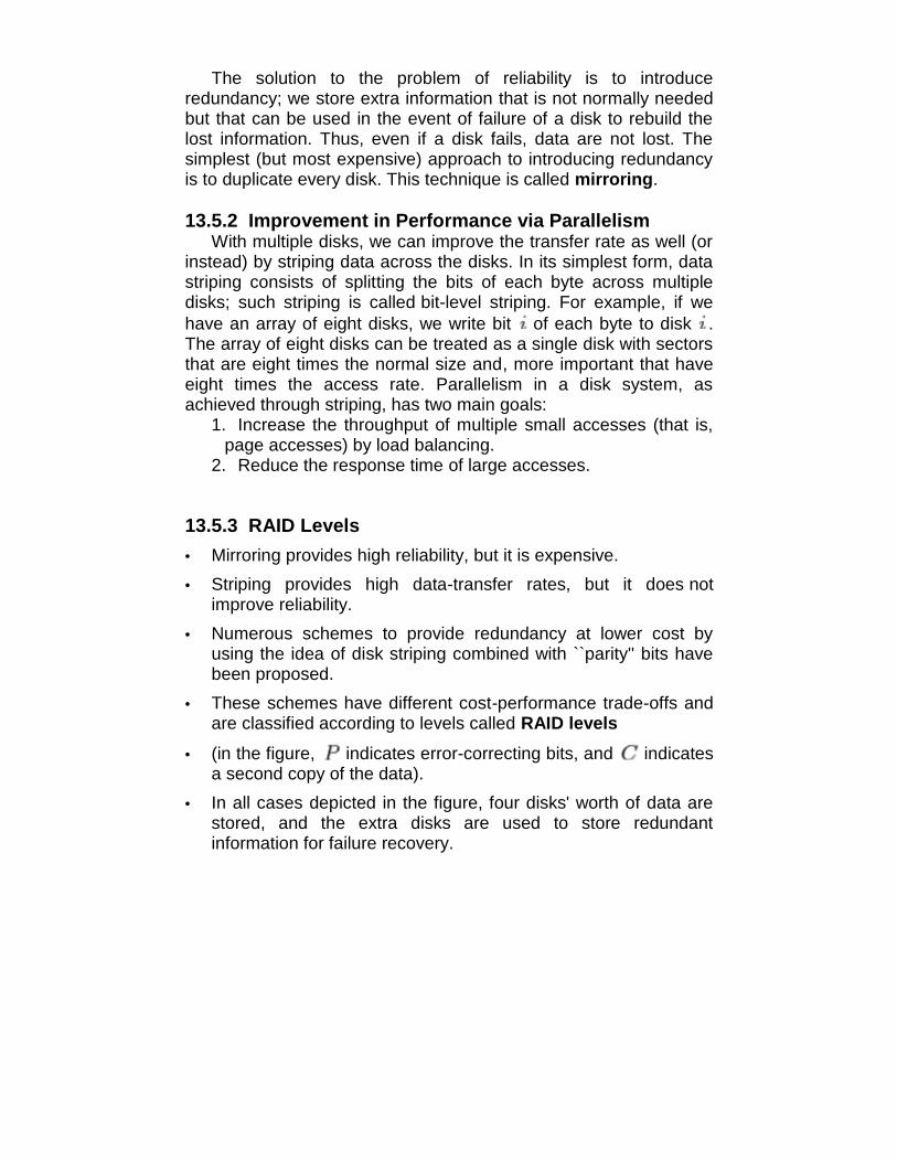
The solution to the problem of reliability is to introduceredundancy; we store extra information that is not normally neededbut that can be used in the event of failure of a disk to rebuild thelost information. Thus, even if a disk fails, data are not lost. Thesimplest (but most expensive) approach to introducing redundancyis to duplicate every disk. This technique is called mirroring.
13.5.2 Improvement in Performance via ParallelismWith multiple disks, we can improve the transfer rate as well (or
instead) by striping data across the disks. In its simplest form, datastriping consists of splitting the bits of each byte across multipledisks; such striping is called bit-level striping. For example, if wehave an array of eight disks, we write bit of each byte to disk .The array of eight disks can be treated as a single disk with sectorsthat are eight times the normal size and, more important that haveeight times the access rate. Parallelism in a disk system, asachieved through striping, has two main goals:
1. Increase the throughput of multiple small accesses (that is,page accesses) by load balancing.
2. Reduce the response time of large accesses.
13.5.3 RAID Levels• Mirroring provides high reliability, but it is expensive.• Striping provides high data-transfer rates, but it does not
improve reliability.• Numerous schemes to provide redundancy at lower cost by
using the idea of disk striping combined with ``parity'' bits havebeen proposed.
• These schemes have different cost-performance trade-offs andare classified according to levels called RAID levels
• (in the figure, indicates error-correcting bits, and indicatesa second copy of the data).
• In all cases depicted in the figure, four disks' worth of data arestored, and the extra disks are used to store redundantinformation for failure recovery.

Fig 13.1 RAID Levels
• RAID Level 0. RAID level 0 refers to disk arrays with striping atthe level of blocks but without any redundancy (such asmirroring or parity bits).
• RAID Level 1. RAID level 1 refers to disk mirroring.• RAID Level 2. RAID level 2 is also known as memory-style
error-correcting-code (ECC) organization. Memory systemshave long detected certain errors by using parity bits.
• RAID Level 3. RAID level 3, or bit-interleaved parityorganization, improves on level 2 by taking into account thefact that, unlike memory systems, disk controllers can detectwhether a sector has been read correctly, so a single parity bitcan be used for error correction as well as for detection.
• RAID Level 4. RAID level 4, or block-interleaved parityorganization, uses block-level striping, as in RAID 0, and in
addition keeps a parity block on a separate disk forcorresponding blocks from other disks.
• RAID Level 5. RAID level 5, or block-interleaved distributedparity, differs from level 4 by spreading data and parity amongall N+1 disks, rather than storing data in disks and parity inone disk. For each block, one of the disks stores the parity, andthe others store data.
• RAID Level 6. RAID level 6, also called the P+Q redundancyscheme, is much like RAID level 5 but stores extra redundantinformation to guard against multiple disk failures.
• RAID Level 0 + 1. RAID level 0 + 1 refers to a combination ofRAID levels 0 and 1. RAID 0 provides the performance, whileRAID 1 provides the reliability. Generally, this level providesbetter performance than RAID 5. It is common in environmentswhere both performance and reliability are important.Unfortunately, it doubles the number of disks needed forstorage, as does RAID I, so it is also more expensive.
13.5.4 Selecting a RAID LevelTrade-offs in selecting the optimal RAID level for a particular
application include cost, volume of data, need for reliability, needfor performance, and rebuild time, the latter of which can affect thelikelihood that a second disk will fail while the first failed disk isbeing rebuilt.
Other decisions include how many disks are involved in aRAID set and how many disks to protect with a single parity bit.More disks in the set increases performance but increases cost.Protecting more disks per parity bit saves cost, but increases thelikelihood that a second disk will fail before the first bad disk isrepaired.
13.5.5 ExtensionsRAID concepts have been extended to tape drives (e.g.
striping tapes for faster backups or parity checking tapes forreliability), and for broadcasting of data.
13.5.6 Problems with RAIDRAID protects against physical errors, but not against any
number of bugs or other errors that could write erroneous data.ZFS (Z file system, developed by Sun™, is a new technologydesigned to use a pooled storage method) adds an extra level ofprotection by including data block checksums in all inodes alongwith the pointers to the data blocks. If data are mirrored and onecopy has the correct checksum and the other does not, then thedata with the bad checksum will be replaced with a copy of the datawith the good checksum. This increases reliability greatly over

RAID alone, at a cost of a performance hit that is acceptablebecause ZFS is so fast to begin with.
Fig 13.2 ZFS checksums all metadata and data
Another problem with traditional file systems is that the sizesare fixed, and relatively difficult to change. Where RAID sets areinvolved it becomes even harder to adjust file system sizes,because a file system cannot span across multiple file systems.
ZFS solves these problems by pooling RAID sets, and bydynamically allocating space to file systems as needed. File systemsizes can be limited by quotas, and space can also be reserved toguarantee that a file system will be able to grow later, but theseparameters can be changed at any time by the file system's owner.Otherwise file systems grow and shrink dynamically as needed.
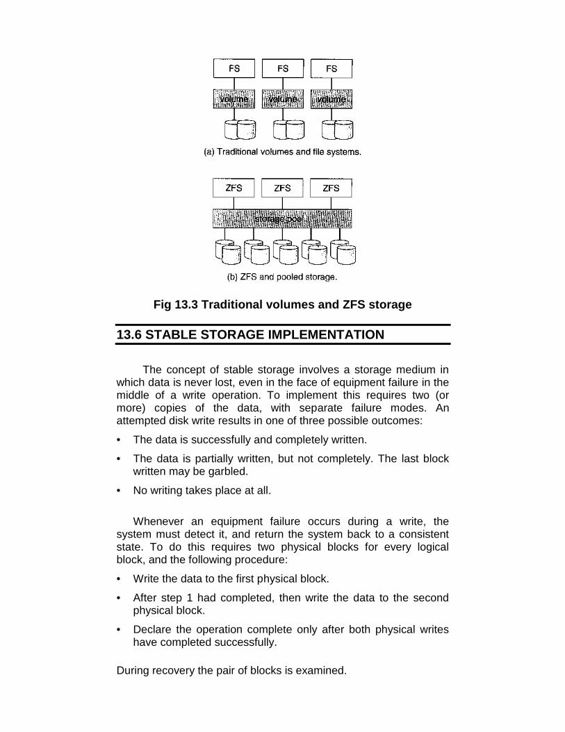
Fig 13.3 Traditional volumes and ZFS storage
13.6 STABLE STORAGE IMPLEMENTATION
The concept of stable storage involves a storage medium inwhich data is never lost, even in the face of equipment failure in themiddle of a write operation. To implement this requires two (ormore) copies of the data, with separate failure modes. Anattempted disk write results in one of three possible outcomes:
• The data is successfully and completely written.
• The data is partially written, but not completely. The last blockwritten may be garbled.
• No writing takes place at all.
Whenever an equipment failure occurs during a write, thesystem must detect it, and return the system back to a consistentstate. To do this requires two physical blocks for every logicalblock, and the following procedure:
• Write the data to the first physical block.
• After step 1 had completed, then write the data to the secondphysical block.
• Declare the operation complete only after both physical writeshave completed successfully.
During recovery the pair of blocks is examined.

• If both blocks are identical and there is no sign of damage, thenno further action is necessary.
• If one block contains a detectable error but the other does not,then the damaged block is replaced with the good copy. (Thiswill either undo the operation or complete the operation,depending on which block is damaged and which isundamaged)
• If neither block shows damage but the data in the blocks differ,then replace the data in the first block with the data in thesecond block. (Undo the operation)
Because the sequence of operations described above is slow,stable storage usually includes NVRAM as a cache, and declares awrite operation complete once it has been written to the NVRAM.
13.7 DEADLOCKS
In a multiprogramming environment, several processes maycompete for a finite number of resources. A process requestsresources; if the resources are not available at that time, theprocess enters a wait state. It may happen that waiting processeswill never again change state, because the resources they haverequested are held by other waiting processes.
If a process requests an instance of a resource type, theallocation of any instance of the type will satisfy the request. If it willnot, then the instances are not identical, and the resource typeclasses have not been defined properly. A process must request aresource before using it, and must release the resource after usingit. A process may request as many resources as it requires to carryout its designated task.
Under the normal mode of operation, a process may utilize aresource in only the following sequence:1. Request: If the request cannot be granted immediately, then the
requesting process must wait until it can acquire the resource.2. Use: The process can operate on the resource.3. Release: The process releases the resource
Deadlock CharacterizationIn deadlock, processes never finish executing and system
resources are tied up, preventing other jobs from ever starting.
Necessary ConditionsA deadlock situation can arise if the following four conditions
hold simultaneously in a system:1. Mutual exclusion: At least one resource must be held in a non-sharable mode; that is, only one process at a time can use the

resource. If another process requests that resource, the requestingprocess must be delayed until the resource has been released.
2. Hold and wait: There must exist a process that is holding atleast one resource and is waiting to acquire additional resourcesthat are currently being held by other processes.
3. No pre-emption: Resources cannot be preempted; that is, aresource can be released only voluntarily by the process holding it,after that process, has completed its task.
4. Circular wait: There must exist a set {P0, P1, ..., Pn} of waitingprocesses such that P0 is waiting for a resource that is held by P1,P1 is waiting for a resource that is held by P2, —, Pn-1 is waiting fora resource that is held by Pn, and Pn is waiting for a resource that isheld by P0.
Resource-Allocation GraphDeadlocks can be described more precisely in terms of a
directed graph called a system resource-allocation graph. The setof vertices V is partitioned into two different types of nodes P = {P0,P1, ..., Pn} the set consisting of all the active processes in thesystem; and R = {R0, R1, ..., Rn}, the set consisting of all resourcetypes in the system.
(a) (b)Fig 13.4 (a) Example of Resource allocation graph
(b) Resource allocation graph with a deadlockA directed edge from process Pi to resource type Rj, is
denoted by PiRj, it signifies that process Pi requested an instanceof resource type Rj and is currently waiting for that resource. Adirected edge from resource type Rj to process Pi is denoted by

RjPi. It signifies that an instance of resource type Rj has beenallocated to process Pi. A directed edge PiRj is called a requestedge; a directed edge RjPi is called an assignment edge.
When process Pi, requests an instance of resource type Rj, arequest edge is inserted in the resource-allocation graph. When thisrequest can be fulfilled the request edge is instantaneouslytransformed to an assignment edge. When the process no longerneeds access to the, resource it releases the resource, and as aresult the assignment edge is deleted.
Definition of a resource-allocation graph, it can be shown that,if the graph contains no cycles, then no process in the system isdeadlocked. If, on the other hand, the graph contains the cycle,then a deadlock must exist.
If each resource type has several instances, then a cycleimplies that a deadlock has occurred. If the cycle involves only aset of resources types, each of which has only a single instance,then a deadlock has occurred. Each process involved in the cycle isdeadlocked. In this case, a cycle in the graph is both a necessaryand a sufficient condition for the existence of deadlock.
Methods for Handling DeadlocksThere are three different methods for dealing with the
deadlock problem:• We can use a protocol to ensure that the system will never enter
a deadlock state.• We can allow the system to enter a deadlock state and then
recover.• We can ignore the problem all together, and pretend that
deadlocks never occur in the system. This solution is the oneused by most operating systems, including UNIX.
Deadlock prevention is a set of methods for ensuring that atleast one of the necessary cannot hold. These methods preventdeadlocks by constraining how requests for resources can bemade.
Deadlock avoidance requires the operating system to have, inadvance, additional information concerning which resources aprocess will request and use during its lifetime. With this additionalknowledge, we can decide for each request whether or not theprocess should wait. Each request requires that the systemconsiders the resources currently available, the resources currentlyallocated to each process, and the future requests and releases ofeach process, to decide whether the current request can besatisfied or must be delayed.
13.1 Deadlock Prevention

For a deadlock to occur, each of the four necessary-conditionsmust hold.
1. Mutual ExclusionThe mutual-exclusion condition must hold for non-sharable
resources. For example, a printer cannot be simultaneously sharedby several processes. Sharable resources, on the other hand, donot require mutually exclusive access, and thus cannot be involvedin a deadlock.
2. Hold and Wait1. When a process requests a resource, it does not hold any other
resources. One protocol that be used requires each process torequest and be allocated all its resources before it beginsexecution.
2. An alternative protocol allows a process to request resourcesonly when the process has none. A process may request someresources and use them. Before it can request any additionalresources, however it must release all the resources that it iscurrently allocated.
There are two main disadvantages to these protocols. First,resource utilization may be low, since many of the resources maybe allocated but unused for a long period. In the example given, forinstance, we can release the tape drive and disk file, and thenagain request the disk file and printer, only if we can be sure thatour data will remain on the disk file.
If we cannot be assured that they will, then we must request allresources at the beginning for both protocols. Second, starvation ispossible.
3. No PreemptionIf a process that is holding some resources requests another
resource that cannot be immediately allocated to it, then allresources currently being held are preempted. That is thisresources are implicitly released. The preempted resources areadded to the list of resources for which the process is waitingprocess will be restarted only when it can regain its old resources,as well as the new ones that it is requesting.
4. Circular WaitCircular-wait condition never holds is to impose a total
ordering of all resource types, and to require that each processrequests resources in an increasing order of enumeration.
Let R = {R1, R2, ..., Rn} be the set of resource types. Weassign to each resource type a unique integer number, whichallows to compare two resources and to determine whether one

precedes another in ordering. Formally, we define a one-to-onefunction F: RN, where N is the set of natural numbers.
13.2 Deadlock AvoidancePrevent deadlocks requests can be made. The restraints
ensure that at least one of the necessary conditions for deadlock tonot occur, and, hence, those deadlocks cannot hold. Possible sideeffects of preventing deadlocks by this, melted, however, are Towdevice utilization and reduced system throughput.
An alternative method for avoiding deadlocks is to requireadditional information about how resources are to be requested.For example, in a system with one tape drive and one printer, wemight be told that process P will request the tape drive first andlater the printer, before releasing both resources. Process Q on theother hand, will request the printer first and then the tape drive.With this knowledge of the complete sequence of requests andreleases for each process we can decide for each request whetheror not the process should wait.
A deadlock-avoidance algorithm dynamically examines theresource-allocation state to ensure there can never be a circularwait condition. The resource-allocation state is defined by thenumber of available and allocated resources, and the maximumdemands of the processes.
1. Safe StateA state is safe if the system allocates resources to each
process (up to its maximum) in some order and still avoid adeadlock. More formally, a system is in a safe state only if there ofprocesses < P1, P2, ..., Pn > is in a safe sequence for the currentallocation state if, for each Pi the resources that Pj can still requestcan be satisfied by the currently available resources plus theresources held by all the Pj, with j<i. In this situation, if theresources that process Pi needs are not immediately available, thenPi can wait until all Pj have finished. When they have finished, Pican obtain all of its needed resources, complete its designatedtask, return its allocated resources, and terminate. When Piterminates, Pi+1 can obtain its needed resources, and so on. If nosuch sequence exists, then the system state is said to be unsafe.

Fig 13.5 Safe, Unsafe deadlock state
2. Resource-Allocation Graph AlgorithmSuppose process Pi requests resource Rj. The request can be
granted only if converting the request edge PiRj to an assignmentedge RjPi does not result in the formation of a cycle in theresource-allocation graph.
(a) (b) Fig 13.6 (a) Resource-Allocation Graph
(b) Unsafe state in Resource-AllocationGraph
3. Banker's AlgorithmThe resource-allocation graph algorithm is not applicable to a
resource-allocation system with multiple instances of each resourcetype. The deadlock-avoidance algorithm that we describe next isapplicable to such a system, but is less efficient than the resource-allocation graph scheme. This algorithm is commonly known as thebanker's algorithm.
13.7.3 Deadlock DetectionIf a system does not employ either a deadlock-prevention or a
deadlock-avoidance algorithm, then a deadlock situation mayoccur.• An algorithm that examines the state of the system to determine
whether a deadlock has occurred• An algorithm to recover from the deadlock
13.7.3.1 Single Instance of Each Resource TypeIf all resources have only a single instance, then we can
define a deadlock detection algorithm that uses a variant of theresource-allocation graph, called a wait-for graph. We obtain thisgraph from the resource-allocation graph by removing the nodes oftype resource and collapsing the appropriate edges.
13.7.3.2 Several Instances of a Resource TypeThe wait-for graph scheme is not applicable to a resource-
allocation system with multiple instances of each resource type.The algorithm used are:
• Available: A vector of length m indicates the number ofavailable resources of each type.
• Allocation: An n x m matrix defines the number of resources ofeach type currently allocated to each process.
• Request: An nxm matrix indicates the current request of eachprocess. If Request[i,j] = k, then process P, is requesting k moreinstances of resource.
13.7.3.3 Detection-Algorithm UsageIf deadlocks occur frequently, then the detection algorithm
should be invoked frequently. Resources allocated to deadlockedprocesses will be idle until the deadlock can be broken.
13.7.4 Recovery from DeadlockWhen a detection algorithm determines that a deadlock exists,
several alternatives exist. One possibility is to inform the operatorthat a deadlock has spurred, and to let the operator deal with thedeadlock manually. The other possibility is to let the system recoverfrom the deadlock automatically.
There are two options for breaking a deadlock. One solution issimply to abort one or more processes to break the circular wait.The second option is to preempt some resources from one or moreof the deadlocked processes.
13.7.4.1 Process TerminationTo eliminate deadlocks by aborting a process, we use one of
two methods. In both methods, the system reclaims all resourcesallocated to the terminated processes.
• Abort all deadlocked processes: This method clearly willbreak the dead - lock cycle, but at a great expense, since theseprocesses may have computed for a long time, and the resultsof these partial computations must be discarded, and probablymust be recomputed
• Abort one process at a time until the deadlock cycle iseliminated: This method incurs considerable overhead, sinceafter each process is aborted a deadlock-detection algorithmmust be invoked to determine whether a processes are stilldeadlocked.
13.7.4.2 Resource PreemptionTo eliminate deadlocks using resource preemption, we
successively preempt some resources from processes and give
these resources to other processes until he deadlock cycle isbroken. The three issues are considered to recover from deadlock
1. Selecting a victim (to minimize cost)2. Rollback (return to some safe state, restart process for that
state)3. Starvation (same process may always be picked as victim,
include number of rollback in cost factor)
13.8 LET US SUM UP
• On media that uses constant linear velocity (CLV), the density ofbits per track is uniform
• The ECC contains enough information, if only a few bits of datahave been corrupted, to enable the controller to identify whichbits have changed and calculate what their correct valuesshould b
• A Master Boot Record (MBR) is the first sector of a datastorage device that has been partitioned.
• A Volume Boot Record (VBR) is the first sector of a datastorage device that has not been partitioned, or the first sectorof an individual partition on a data storage device that has beenpartitioned.
• A bad sector is a sector on a computer's disk drive or flashmemory that cannot be used due to permanent damage (or anOS inability to successfully access it), such as physical damageto the disk surface (or sometimes sectors being stuck in amagnetic or digital state that cannot be reversed) or failed flashmemory transistors.
• Swap-space management refers to the process where OSbreaks the physical RAM that is structured with random accessmemory into some pitches of memory called pages.
• A variety of disk-organization techniques, collectivelycalled redundant arrays of inexpensive disks (RAIDs) arecommonly used to address the performance and reliabilityissues.
• The solution to the problem of reliability is to introduceredundancy; we store extra information that is not normallyneeded but that can be used in the event of failure of a disk torebuild the lost information
• Whenever an equipment failure occurs during a write, thesystem must detect it, and return the system back to aconsistent state
• In deadlock, processes never finish executing and systemresources are tied up, preventing other jobs from ever starting

• If each resource type has several instances, then a cycleimplies that a deadlock has occurred.
• Deadlock prevention is a set of methods for ensuring that atleast one of the necessary cannot hold
• Deadlock avoidance requires the operating system to have, inadvance, additional information concerning which resources aprocess will request and use during its lifetime
13.9 UNIT END QUESTIONS
1. Define boot block and bad blocks.2. Describe various RAID levels with the help of diagrams.3. What are deadlocks? What are the necessary conditions arised
in a deadlock situation?4. How to:
a) Detect a deadlockb) Recover from a deadlock
5. Definea. Low-level formattingb. Swap Spacec. RAIDd. Mirroring

14
I/O SYSTEMS
Unit Structure14.0 Objectives14.1 Introduction14.2 Application I/O Interface
14.2.1 Block and Character Devices14.2.2 Network Devices14.2.3 Clocks and timers14.2.4 Blocking and non-blocking I/O
14.3 Transforming I/O Requests to Hardware Operations14.4 Streams14.5 Performance14.6 Let Us Sum Up14.7 Unit End Questions
14.0 OBJECTIVES
After reading this unit you will be able to:• Discuss structuring techniques and interfaces for the operating
system that enable I/0 devices to be treated in a standard,uniform way.
• Explain how an application can open a file on a disk withoutknowing what kind of disk it is and how new disks and otherdevices can be added to a computer without disruption of theoperating system
14.1 INTRODUCTION
Management of I/O devices is a very important part of theoperating system - so important and so varied that entire I/Osubsystems are devoted to its operation. (Consider the range ofdevices on a modern computer, from mice, keyboards, disk drives,display adapters, USB devices, network connections, audio I/O,printers, special devices for the handicapped, and many special-purpose peripherals)
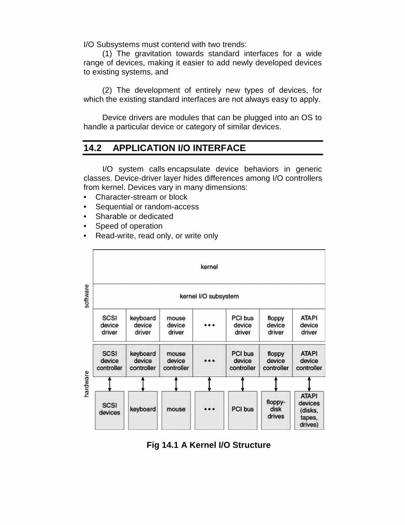
I/O Subsystems must contend with two trends:(1) The gravitation towards standard interfaces for a wide
range of devices, making it easier to add newly developed devicesto existing systems, and
(2) The development of entirely new types of devices, forwhich the existing standard interfaces are not always easy to apply.
Device drivers are modules that can be plugged into an OS tohandle a particular device or category of similar devices.
14.2 APPLICATION I/O INTERFACE
I/O system calls encapsulate device behaviors in genericclasses. Device-driver layer hides differences among I/O controllersfrom kernel. Devices vary in many dimensions:• Character-stream or block• Sequential or random-access• Sharable or dedicated• Speed of operation• Read-write, read only, or write only
Fig 14.1 A Kernel I/O Structure
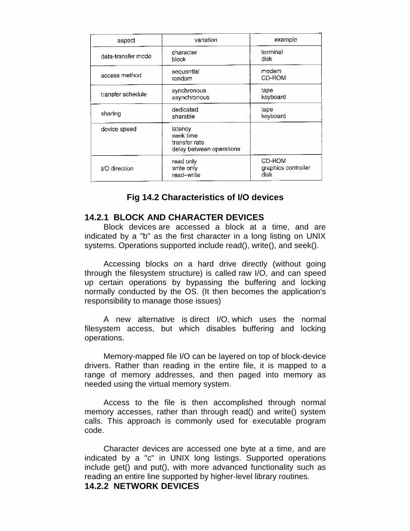
Fig 14.2 Characteristics of I/O devices
14.2.1 BLOCK AND CHARACTER DEVICESBlock devices are accessed a block at a time, and are
indicated by a "b" as the first character in a long listing on UNIXsystems. Operations supported include read(), write(), and seek().
Accessing blocks on a hard drive directly (without goingthrough the filesystem structure) is called raw I/O, and can speedup certain operations by bypassing the buffering and lockingnormally conducted by the OS. (It then becomes the application'sresponsibility to manage those issues)
A new alternative is direct I/O, which uses the normalfilesystem access, but which disables buffering and lockingoperations.
Memory-mapped file I/O can be layered on top of block-devicedrivers. Rather than reading in the entire file, it is mapped to arange of memory addresses, and then paged into memory asneeded using the virtual memory system.
Access to the file is then accomplished through normalmemory accesses, rather than through read() and write() systemcalls. This approach is commonly used for executable programcode.
Character devices are accessed one byte at a time, and areindicated by a "c" in UNIX long listings. Supported operationsinclude get() and put(), with more advanced functionality such asreading an entire line supported by higher-level library routines.14.2.2 NETWORK DEVICES
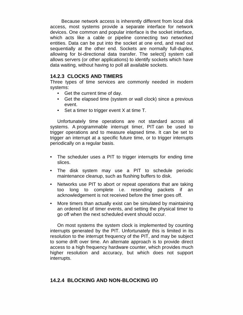
Because network access is inherently different from local diskaccess, most systems provide a separate interface for networkdevices. One common and popular interface is the socket interface,which acts like a cable or pipeline connecting two networkedentities. Data can be put into the socket at one end, and read outsequentially at the other end. Sockets are normally full-duplex,allowing for bi-directional data transfer. The select() system callallows servers (or other applications) to identify sockets which havedata waiting, without having to poll all available sockets.
14.2.3 CLOCKS AND TIMERSThree types of time services are commonly needed in modernsystems:
• Get the current time of day.• Get the elapsed time (system or wall clock) since a previous
event.• Set a timer to trigger event X at time T.
Unfortunately time operations are not standard across allsystems. A programmable interrupt timer, PIT can be used totrigger operations and to measure elapsed time. It can be set totrigger an interrupt at a specific future time, or to trigger interruptsperiodically on a regular basis.
• The scheduler uses a PIT to trigger interrupts for ending timeslices.
• The disk system may use a PIT to schedule periodicmaintenance cleanup, such as flushing buffers to disk.
• Networks use PIT to abort or repeat operations that are takingtoo long to complete i.e. resending packets if anacknowledgement is not received before the timer goes off.
• More timers than actually exist can be simulated by maintainingan ordered list of timer events, and setting the physical timer togo off when the next scheduled event should occur.
On most systems the system clock is implemented by countinginterrupts generated by the PIT. Unfortunately this is limited in itsresolution to the interrupt frequency of the PIT, and may be subjectto some drift over time. An alternate approach is to provide directaccess to a high frequency hardware counter, which provides muchhigher resolution and accuracy, but which does not supportinterrupts.
14.2.4 BLOCKING AND NON-BLOCKING I/O

With blocking I/O a process is moved to the wait queue whenan I/O request is made, and moved back to the ready queue whenthe request completes, allowing other processes to run in themeantime.
With non-blocking I/O the I/O request returns immediately,whether the requested I/O operation has (completely) occurred ornot. This allows the process to check for available data withoutgetting hung completely if it is not there.
One approach for programmers to implement non-blocking I/Ois to have a multi-threaded application, in which one thread makesblocking I/O calls (say to read a keyboard or mouse), while otherthreads continue to update the screen or perform other tasks.
A subtle variation of the non-blocking I/O is the asynchronousI/O, in which the I/O request returns immediately allowing theprocess to continue on with other tasks, and then the process isnotified (via changing a process variable, or a software interrupt, ora callback function) when the I/O operation has completed and thedata is available for use. (The regular non-blocking I/O returnsimmediately with whatever results are available, but does notcomplete the operation and notify the process later)
(a) (b)Fig14.3 Two I/O methods: (a) synchronous and(b) asynchronous
14.3 TRANSFORMING I/O REQUESTS TOHARDWARE OPERATIONS
Users request data using file names, which must ultimatelybe mapped to specific blocks of data from a specific devicemanaged by a specific device driver.
DOS uses the colon separator to specify a particular device(e.g. C:, LPT:, etc.). UNIX uses a mount table to map filenameprefixes (e.g. /usr) to specific mounted devices. Where multipleentries in the mount table match different prefixes of the filename

the one that matches the longest prefix is chosen. (e.g. /usr/homeinstead of /usr where both exist in the mount table and both matchthe desired file)
UNIX uses special device files, usually located in /dev, torepresent and access physical devices directly.
Each device file has a major and minor number associatedwith it, stored and displayed where the file size would normally go.The major number is an index into a table of device drivers, andindicates which device driver handles this device. (E.g. the diskdrive handler).
The minor number is a parameter passed to the device driver,and indicates which specific device is to be accessed, out of themany which may be handled by a particular device driver. (e.g. aparticular disk drive or partition).
A series of lookup tables and mappings makes the access ofdifferent devices flexible, and somewhat transparent to users.Figure 14.4 illustrates the steps taken to process a (blocking) readrequest:

Fig 14.4 The life cycle of an I/O request
14.4 STREAMS

The streams mechanism in UNIX provides a bi-directionalpipeline between a user process and a device driver, onto whichadditional modules can be added.
The user process interacts with the stream head. The devicedriver interacts with the device end. Zero or more streammodules can be pushed onto the stream, using ioctl(). Thesemodules may filter and/or modify the data as it passes through thestream.
Each module has a read queue and a write queue. Flowcontrol can be optionally supported, in which case each module willbuffer data until the adjacent module is ready to receive it. Withoutflow control, data is passed along as soon as it is ready.
User processes communicate with the stream head usingeither read() and write() [or putmsg() and getmsg() for messagepassing]. Streams I/O is asynchronous (non-blocking), except forthe interface between the user process and the stream head.
The device driver must respond to interrupts from its device -If the adjacent module is not prepared to accept data and thedevice driver's buffers are all full, then data is typically dropped.
Streams are widely used in UNIX, and are the preferredapproach for device drivers. For example, UNIX implementssockets using streams.

Fig 14.5 The STREAMS architecture
14.5 PERFORMANCE
The I/O system is a major factor in overall systemperformance, and can place heavy loads on other majorcomponents of the system (interrupt handling, process switching,memory access, bus contention, and CPU load for device driversjust to name a few)
Interrupt handling can be relatively expensive (slow), whichcauses programmed I/O to be faster than interrupt-driven I/O whenthe time spent busy waiting is not excessive.
Network traffic can also put a heavy load on the system.Consider for example the sequence of events that occur when asingle character is typed in a telnet session, as shown in figure14.6. (And the fact that a similar set of events must happen inreverse to echo back the character that was typed) Sun uses in-kernel threads for the telnet daemon, increasing the supportablenumber of simultaneous telnet sessions from the hundreds to thethousands.

Fig 14.6 Intercomputer Communications
Other systems use front-end processors to off-load some ofthe work of I/O processing from the CPU. For example a terminalconcentrator can multiplex with hundreds of terminals on a singleport on a large computer.
Several principles can be employed to increase the overallefficiency of I/O processing:
• Reduce the number of context switches.
• Reduce the number of times data must be copied.
• Reduce interrupt frequency, using large transfers, buffering, andpolling where appropriate.
• Increase concurrency using DMA.
• Move processing primitives into hardware, allowing theiroperation to be concurrent with CPU and bus operations.

• Balance CPU, memory, bus, and I/O operations, so a bottleneckin one does not idle all the others.
The development of new I/O algorithms often follows aprogression from application level code to on-board hardwareimplementation, as shown in Figure 14.7. Lower-levelimplementations are faster and more efficient, but higher-level onesare more flexible and easier to modify. Hardware-level functionalitymay also be harder for higher-level authorities (e.g. the kernel) tocontrol.
Fig 14.7 Device Functionality Progression
14.6 LET US SUM UP
• Devices vary in many dimensions:o Character-stream or blocko Sequential or random-accesso Sharable or dedicatedo Speed of operationo Read-write, read only, or write only
• Block devices are accessed a block at a time, and are indicatedby a "b" as the first character in a long listing on UNIX systems
• The select() system call allows servers (or other applications) toidentify sockets which have data waiting, without having to pollall available sockets.
• One approach for programmers to implement non-blocking I/Ois to have a multi-threaded application, in which one threadmakes blocking I/O calls (say to read a keyboard or mouse),

while other threads continue to update the screen or performother tasks.
• Each device file has a major and minor number associated withit, stored and displayed where the file size would normally go.
• A series of lookup tables and mappings makes the access ofdifferent devices flexible, and somewhat transparent to users.
• The streams mechanism in UNIX provides a bi-directionalpipeline between a user process and a device driver, onto whichadditional modules can be added.
• Streams I/O is asynchronous (non-blocking), except for theinterface between the user process and the stream head.
• The development of new I/O algorithms often follows aprogression from application level code to on-board hardwareimplementation.
14.7 UNIT END QUESTIONS
7. State some characteristics of I/O devices.8. Write a short note on Blocking and non-blocking I/O9. Describe the life cycle of an I/O request with the help of a
diagram.10.What are STREAMS?11.State various principles employed to increase the overall
efficiency of I/O processing.

15
PROTECTION AND SECURITY
Unit Structure15.0 Objectives15.1 Introduction15.2 Principles of protection15.3 Domain of protection
15.3.1 Domain Structure15.3.2 An Example: Unix
15.4 Access Matrix15.5 Access Control15.6 Capability-Based Systems
15.6.1 An Example: Hydra15.6.2 An Example: Cambridge Cap System
15.7 Language Based Protection15.7.1 Compiler-Based Enforcement15.7.2 Protection in java
15.8 The Security Problem15.9 System and Network Threats
15.9.1 Worms15.9.2 Port Scanning15.9.3 Denial of service
15.10 Implementing Securoty Defenses15.10.1 Security Policy15.10.2 Vulnerability Assessment15.10.3 Intrusion Detection15.10.4 Virus Protection15.10.5 Auditing, Accounting, and Logging
15.11 Let Us Sum Up15.12 Unit End Questions
15.0 OBJECTIVES

After studying this unit, you will be able:
• To ensure that each shared resource is used only in accordancewith system policies, which may be set either by systemdesigners or by system administrators.
• To ensure that errant programs cause the minimal amount ofdamage possible.
• Note that protection systems only provide the mechanisms forenforcing policies and ensuring reliable systems. It is up toadministrators and users to implement those mechanismseffectively.
15.1 INTRODUCTION
The role of protection in a computer system is to provide amechanism for the enforcement of the policies governing resourceuse. These policies can be established in a variety of ways. Someare fixed in the design of the system, while others are formulated bythe management of a system. Still others are defined by theindividual users to protect their own files and programs. Aprotection system must have the flexibility to enforce a variety ofpolicies.
15.2 PRINCIPLES OF PROTECTION
The principle of least privilege dictates that programs, users,and systems be given just enough privileges to perform their tasks.This ensures that failures do the least amount of harm and allowthe least of harm to be done.
For example, if a program needs special privileges to performa task, it is better to make it a SGID program with group ownershipof "network" or "backup" or some other pseudo group, rather thanSUID with root ownership. This limits the amount of damage thatcan occur if something goes wrong.
Typically each user is given their own account, and has onlyenough privilege to modify their own files. The root account shouldnot be used for normal day to day activities - The SystemAdministrator should also have an ordinary account, and reserveuse of the root account for only those tasks which need the rootprivileges
15.3 DOMAIN OF PROTECTION
A computer can be viewed as a collection of processes andobjects (both hardware and software).

The need to know principle states that a process should onlyhave access to those objects it needs to accomplish its task, andfurthermore only in the modes for which it needs access and onlyduring the time frame when it needs access. The modes availablefor a particular object may depend upon its type.
15.3.1 Domain StructureA protection domain specifies the resources that a process
may access. Each domain defines a set of objects and the types ofoperations that may be invoked on each object. An access right isthe ability to execute an operation on an object.
A domain is defined as a set of < object, { access right set } >pairs, as shown below. Note that some domains may be disjointwhile others overlap.
Fig 15.1 System with three protection domains
The association between a process and a domain maybe static or dynamic. If the association is static, then the need-to-know principle requires a way of changing the contents of thedomain dynamically. If the association is dynamic, then there needsto be a mechanism for domain switching.
Domains may be realized in different fashions - as users, oras processes, or as procedures. E.g. if each user corresponds to adomain, then that domain defines the access of that user, andchanging domains involves changing user ID.
15.3.2 An Example: UNIXUNIX associates domains with users. Certain programs
operate with the SUID bit set, which effectively changes the userID, and therefore the access domain, while the program is running(and similarly for the SGID bit). Unfortunately this has somepotential for abuse.
An alternative used on some systems is to place privilegedprograms in special directories, so that they attain the identity of thedirectory owner when they run. This prevents crackers from placingSUID programs in random directories around the system.
Yet another alternative is to not allow the changing of ID at all.Instead, special privileged daemons are launched at boot time, and

user processes send messages to these daemons when they needspecial tasks performed.
15.4 ACCESS MATRIX
The model of protection that we have been discussing can beviewed as an access matrix, in which columns represent differentsystem resources and rows represent different protection domains.Entries within the matrix indicate what access that domain has tothat resource.
Fig 15.2 Access MatrixDomain switching can be easily supported under this model, simplyby providing "switch" access to other domains:
Fig 15.3 Access matrix of fig.15.2 with domains as objectsThe ability to copy rights is denoted by an asterisk, indicating
that processes in that domain have the right to copy that accesswithin the same column, i.e. for the same object. There are twoimportant variations:
If the asterisk is removed from the original access right, thenthe right is transferred, rather than being copied. This may betermed a transfer right as opposed to a copy right.
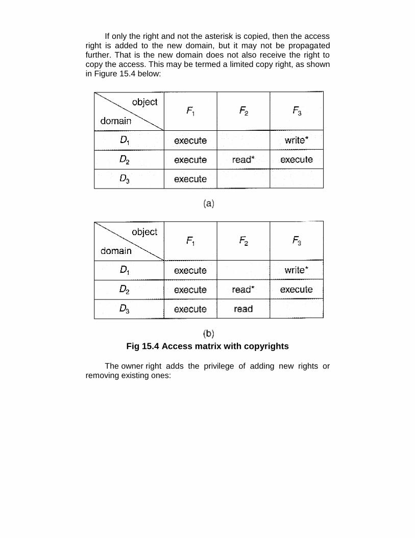
If only the right and not the asterisk is copied, then the accessright is added to the new domain, but it may not be propagatedfurther. That is the new domain does not also receive the right tocopy the access. This may be termed a limited copy right, as shownin Figure 15.4 below:
Fig 15.4 Access matrix with copyrights
The owner right adds the privilege of adding new rights orremoving existing ones:
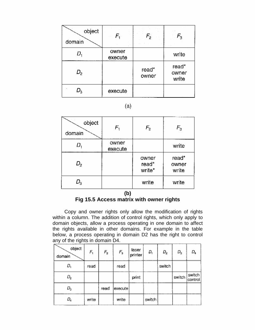
(b)Fig 15.5 Access matrix with owner rights
Copy and owner rights only allow the modification of rightswithin a column. The addition of control rights, which only apply todomain objects, allow a process operating in one domain to affectthe rights available in other domains. For example in the tablebelow, a process operating in domain D2 has the right to controlany of the rights in domain D4.
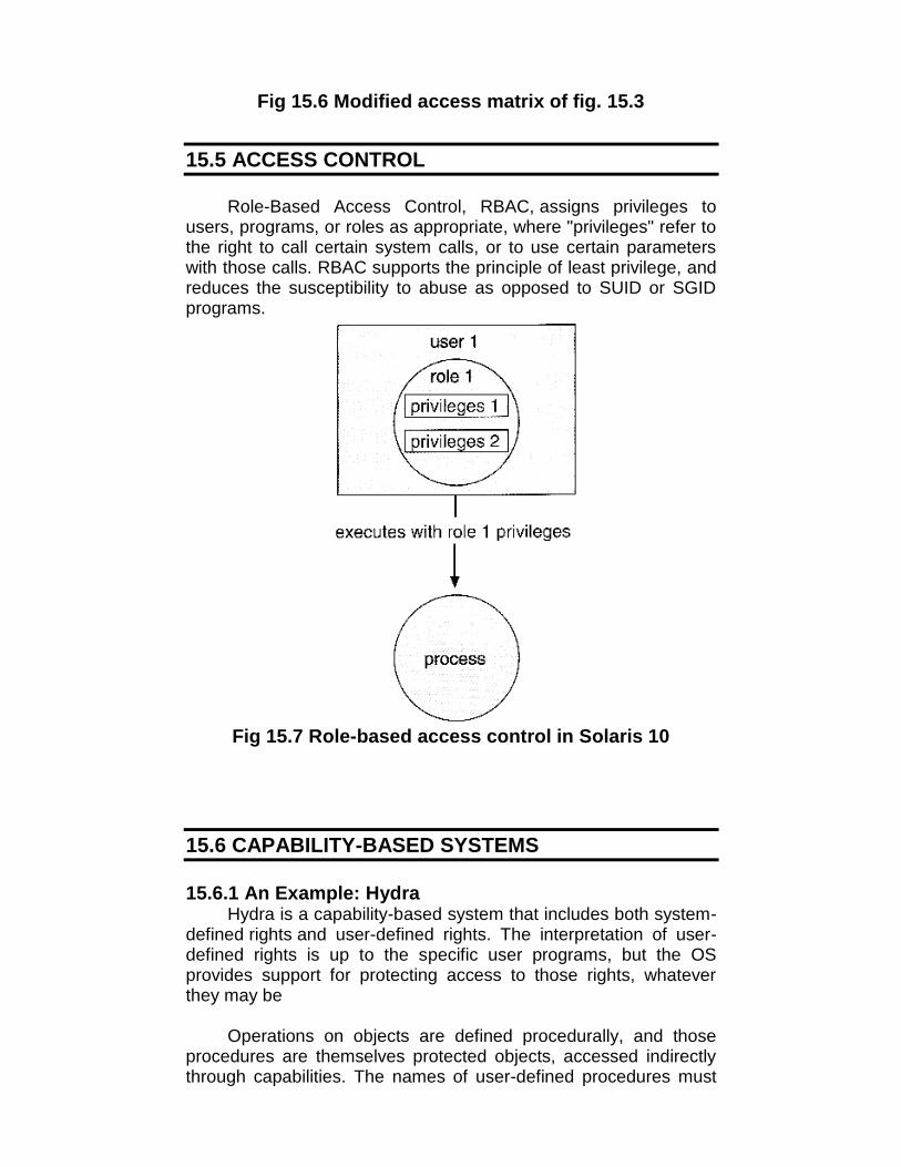
Fig 15.6 Modified access matrix of fig. 15.3
15.5 ACCESS CONTROL
Role-Based Access Control, RBAC, assigns privileges tousers, programs, or roles as appropriate, where "privileges" refer tothe right to call certain system calls, or to use certain parameterswith those calls. RBAC supports the principle of least privilege, andreduces the susceptibility to abuse as opposed to SUID or SGIDprograms.
Fig 15.7 Role-based access control in Solaris 10
15.6 CAPABILITY-BASED SYSTEMS
15.6.1 An Example: HydraHydra is a capability-based system that includes both system-
defined rights and user-defined rights. The interpretation of user-defined rights is up to the specific user programs, but the OSprovides support for protecting access to those rights, whateverthey may be
Operations on objects are defined procedurally, and thoseprocedures are themselves protected objects, accessed indirectlythrough capabilities. The names of user-defined procedures must
be identified to the protection system if it is to deal with user-defined rights.
When an object is created, the names of operations definedon that object become auxiliary rights, described in a capability foran instance of the type. For a process to act on an object, thecapabilities it holds for that object must contain the name of theoperation being invoked. This allows access to be controlled on aninstance-by-instance and process-by-process basis.
Hydra also allows rights amplification, in which a process isdeemed to be trustworthy, and thereby allowed to act on any objectcorresponding to its parameters.
Programmers can make direct use of the Hydra protectionsystem, using suitable libraries which are documented inappropriate reference manuals.
15.6.2 An Example: Cambridge CAP System
The CAP system has two kinds of capabilities:• Data capability, used to provide read, write, and execute access
to objects. These capabilities are interpreted by microcode inthe CAP machine.
• Software capability, is protected but not interpreted by the CAPmicrocode.
Software capabilities are interpreted by protected (privileged)procedures, possibly written by application programmers.
When a process executes a protected procedure, ittemporarily gains the ability to read or write the contents of asoftware capability. This leaves the interpretation of the softwarecapabilities up to the individual subsystems, and limits the potentialdamage that could be caused by a faulty privileged procedure.
Note, however, that protected procedures only get access tosoftware capabilities for the subsystem of which they are a part.Checks are made when passing software capabilities to protectedprocedures that they are of the correct type.
Unfortunately the CAP system does not provide libraries,making it harder for an individual programmer to use than theHydra system.
15.7 LANGUAGE-BASED PROTECTION
As systems have developed, protection systems have becomemore powerful, and also more specific and specialized. To refine

protection even further requires putting protection capabilities intothe hands of individual programmers, so that protection policies canbe implemented on the application level, i.e. to protect resources inways that are known to the specific applications but not to the moregeneral operating system.
15.7.1 Compiler-Based EnforcementIn a compiler-based approach to protection enforcement,
programmers directly specify the protection needed for differentresources at the time the resources are declared.
This approach has several advantages:1. Protection needs are simply declared, as opposed to a complex
series of procedure calls.2. Protection requirements can be stated independently of the
support provided by a particular OS.3. The means of enforcement need not be provided directly by the
developer.4. Declarative notation is natural, because access privileges are
closely related to the concept of data types.
Regardless of the means of implementation, compiler-basedprotection relies upon the underlying protection mechanismsprovided by the underlying OS, such as the Cambridge CAP orHydra systems.
Even if the underlying OS does not provide advanced protectionmechanisms, the compiler can still offer some protection, such astreating memory accesses differently in code versus datasegments. (E.g. code segments cant be modified, data segmentscan't be executed)
There are several areas in which compiler-based protection canbe compared to kernel-enforced protection:
SecuritySecurity provided by the kernel offers better protection than
that provided by a compiler. The security of the compiler-basedenforcement is dependent upon the integrity of the compiler itself,as well as requiring that files not be modified after they arecompiled. The kernel is in a better position to protect itself frommodification, as well as protecting access to specific files. Wherehardware support of individual memory accesses is available, theprotection is stronger still.
FlexibilityA kernel-based protection system is not as flexible to provide
the specific protection needed by an individual programmer, though
it may provide support which the programmer may make use of.Compilers are more easily changed and updated when necessaryto change the protection services offered or their implementation.
EfficiencyThe most efficient protection mechanism is one supported by
hardware and microcode. Insofar as software based protection isconcerned, compiler-based systems have the advantage that manychecks can be made off-line, at compile time, rather that duringexecution.
The concept of incorporating protection mechanisms intoprogramming languages is in its infancy, and still remains to be fullydeveloped. However the general goal is to provide mechanisms forthree functions:
1. Distributing capabilities safely and efficiently among customerprocesses. In particular a user process should only be able toaccess resources for which it was issued capabilities.
2. Specifying the type of operations a process may execute on aresource, such as reading or writing.
3. Specifying the order in which operations are performed on theresource, such as opening before reading.
15.7.2 Protection in JavaJava was designed from the very beginning to operate in a
distributed environment, where code would be executed from avariety of trusted and untrusted sources. As a result the JavaVirtual Machine, JVM incorporates many protection mechanisms
When a Java program runs, it load up classes dynamically, inresponse to requests to instantiates objects of particular types.These classes may come from a variety of different sources, sometrusted and some not, which requires that the protectionmechanism be implemented at the resolution of individual classes,something not supported by the basic operating system.
As each class is loaded, it is placed into a separate protectiondomain. The capabilities of each domain depend upon whether thesource URL is trusted or not, the presence or absence of any digitalsignatures on the class, and a configurable policy file indicatingwhich servers a particular user trusts, etc.
When a request is made to access a restricted resource inJava, (e.g. open a local file), some process on the current callstack must specifically assert a privilege to perform the operation.In essence this method assumes responsibility for the restrictedaccess. Naturally the method must be part of a class which residesin a protection domain that includes the capability for the requested
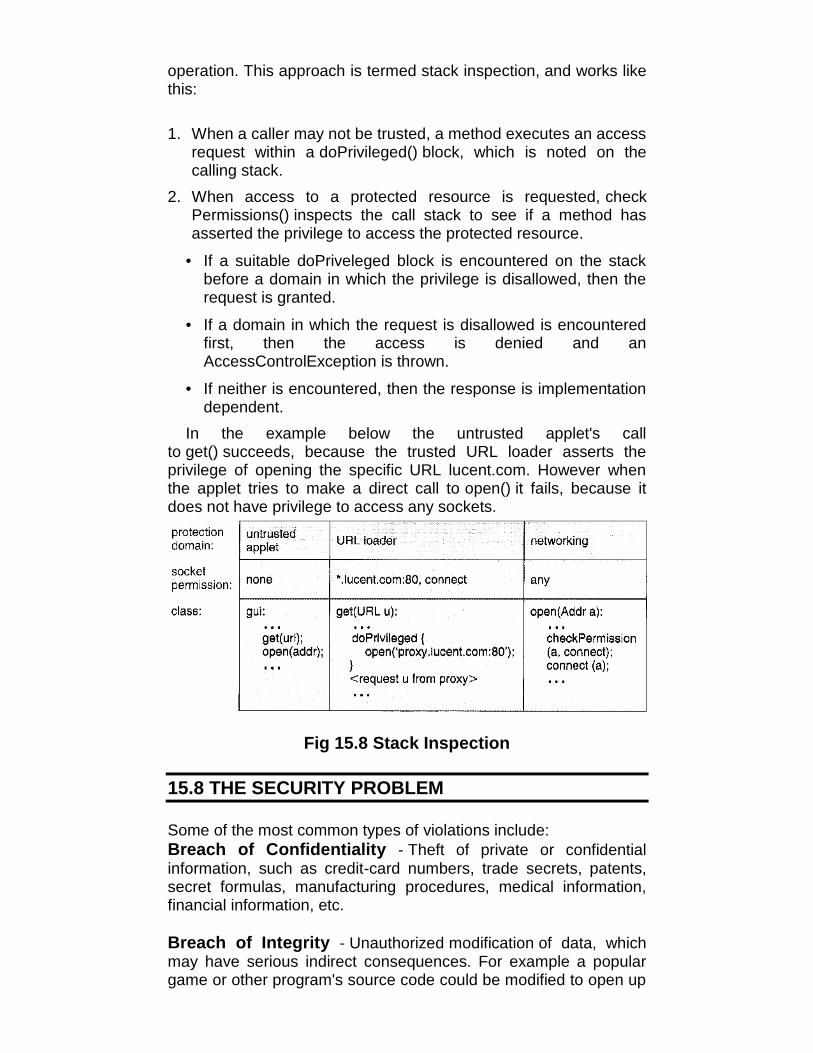
operation. This approach is termed stack inspection, and works likethis:
1. When a caller may not be trusted, a method executes an accessrequest within a doPrivileged() block, which is noted on thecalling stack.
2. When access to a protected resource is requested, checkPermissions() inspects the call stack to see if a method hasasserted the privilege to access the protected resource.
• If a suitable doPriveleged block is encountered on the stackbefore a domain in which the privilege is disallowed, then therequest is granted.
• If a domain in which the request is disallowed is encounteredfirst, then the access is denied and anAccessControlException is thrown.
• If neither is encountered, then the response is implementationdependent.
In the example below the untrusted applet's callto get() succeeds, because the trusted URL loader asserts theprivilege of opening the specific URL lucent.com. However whenthe applet tries to make a direct call to open() it fails, because itdoes not have privilege to access any sockets.
Fig 15.8 Stack Inspection
15.8 THE SECURITY PROBLEM
Some of the most common types of violations include:Breach of Confidentiality - Theft of private or confidentialinformation, such as credit-card numbers, trade secrets, patents,secret formulas, manufacturing procedures, medical information,financial information, etc.
Breach of Integrity - Unauthorized modification of data, whichmay have serious indirect consequences. For example a populargame or other program's source code could be modified to open up
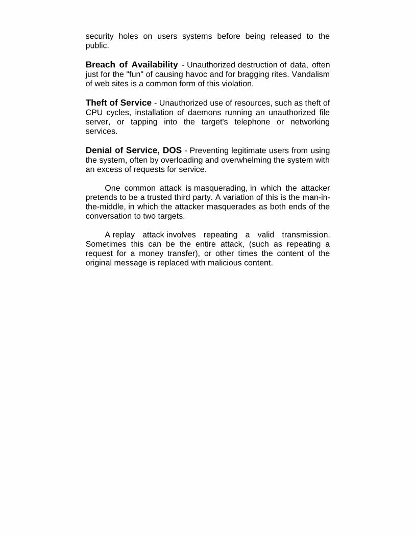
security holes on users systems before being released to thepublic.
Breach of Availability - Unauthorized destruction of data, oftenjust for the "fun" of causing havoc and for bragging rites. Vandalismof web sites is a common form of this violation.
Theft of Service - Unauthorized use of resources, such as theft ofCPU cycles, installation of daemons running an unauthorized fileserver, or tapping into the target's telephone or networkingservices.
Denial of Service, DOS - Preventing legitimate users from usingthe system, often by overloading and overwhelming the system withan excess of requests for service.
One common attack is masquerading, in which the attackerpretends to be a trusted third party. A variation of this is the man-in-the-middle, in which the attacker masquerades as both ends of theconversation to two targets.
A replay attack involves repeating a valid transmission.Sometimes this can be the entire attack, (such as repeating arequest for a money transfer), or other times the content of theoriginal message is replaced with malicious content.
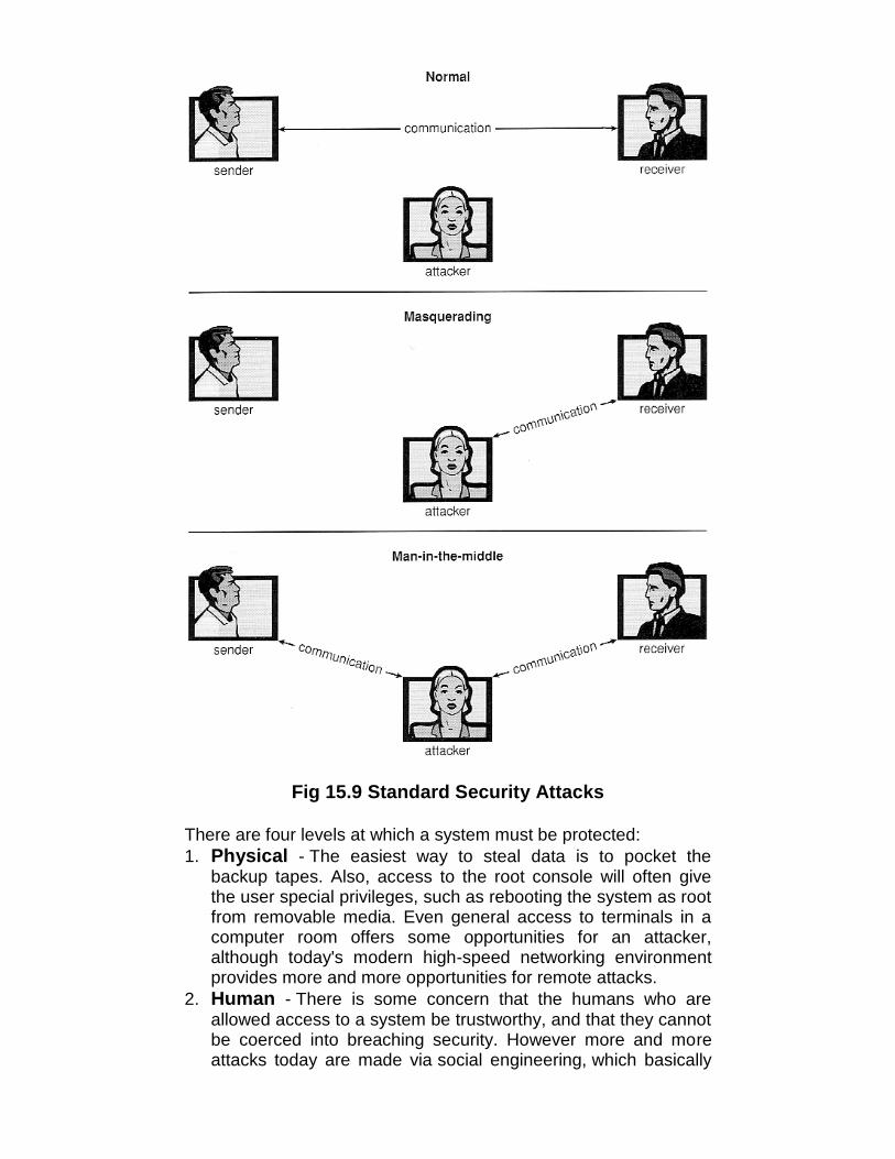
Fig 15.9 Standard Security Attacks
There are four levels at which a system must be protected:1. Physical - The easiest way to steal data is to pocket the
backup tapes. Also, access to the root console will often givethe user special privileges, such as rebooting the system as rootfrom removable media. Even general access to terminals in acomputer room offers some opportunities for an attacker,although today's modern high-speed networking environmentprovides more and more opportunities for remote attacks.
2. Human - There is some concern that the humans who areallowed access to a system be trustworthy, and that they cannotbe coerced into breaching security. However more and moreattacks today are made via social engineering, which basically
means fooling trustworthy people into accidentally breachingsecurity.
• Phishing involves sending an innocent-looking e-mail or website designed to fool people into revealing confidentialinformation. E.g. spam e-mails pretending to be from e-Bay,PayPal, or any of a number of banks or credit-card companies.
• Dumpster Diving involves searching the trash or otherlocations for passwords that are written down. (Note: Passwordsthat are too hard to remember, or which must be changedfrequently are more likely to be written down somewhere closeto the user's station.)
• Password Cracking involves divining users passwords, eitherby watching them type in their passwords, knowing somethingabout them like their pet's names, or simply trying all words incommon dictionaries. (Note: "Good" passwords should involve aminimum number of characters, include non-alphabeticalcharacters, and not appear in any dictionary (in any language),and should be changed frequently. Also note that it is properetiquette to look away from the keyboard while someone else isentering their password.)
3. Operating System - The OS must protect itself from securitybreaches, such as runaway processes (denial of service),memory-access violations, stack overflow violations, thelaunching of programs with excessive privileges, and manyothers.
4. Network - As network communications become ever moreimportant and pervasive in modern computing environments, itbecomes ever more important to protect this area of the system.(Both protecting the network itself from attack, and protectingthe local system from attacks coming in through the network.)This is a growing area of concern as wireless communicationsand portable devices become more and more prevalent.
15.9 SYSTEM AND NETWORK THREATS
Most of the threats described above are termed programthreats, because they attack specific programs or are carried anddistributed in programs. The threats in this section attack theoperating system or the network itself, or leverage those systems tolaunch their attacks.
15.9.1 WormsA worm is a process that uses the fork / spawn process to
make copies of itself in order to wreak havoc on a system. Worms

consume system resources, often blocking out other, legitimateprocesses. Worms that propagate over networks can be especiallyproblematic, as they can tie up vast amounts of network resourcesand bring down large-scale systems.
One of the most well-known worms was launched by RobertMorris, a graduate student at Cornell, in November 1988. TargetingSun and VAX computers running BSD UNIX version 4, the wormspanned the Internet in a matter of a few hours, and consumedenough resources to bring down many systems.
This worm consisted of two parts: A small program calleda grappling hook, which was deposited on the target systemthrough one of three vulnerabilities, and the main worm program,which was transferred onto the target system and launched by thegrappling hook program.
Fig 15.10 The Morris Internet WORM
The three vulnerabilities exploited by the Morris Internet worm wereas follows:
1. rsh (remote shell) is a utility that was in common use at thattime for accessing remote systems without having to provide apassword. If a user had an account on two different computers(with the same account name on both systems), then thesystem could be configured to allow that user to remotelyconnect from one system to the other without having to providea password. Many systems were configured so that any user(except root) on system A could access the same account onsystem B without providing a password.
2. finger is a utility that allows one to remotely query a userdatabase, to find the true name and other information for agiven account name on a given system. For example "[email protected]" would access the finger daemonat somemachine.edu and return information regarding joeUser.

Unfortunately the finger daemon (which ran with systemprivileges) had the buffer overflow problem, so by sending aspecial 536-character user name the worm was able to fork ashell on the remote system running with root privileges.
3. sendmail is a routine for sending and forwarding mail that alsoincluded a debugging option for verifying and testing thesystem. The debug feature was convenient for administrators,and was often left turned on. The Morris worm exploited thedebugger to mail and execute a copy of the grappling hookprogram on the remote system.
Once in place, the worm undertook systematic attacks to discoveruser passwords:
1. First it would check for accounts for which the account nameand the password were the same, such as "guest", "guest".
2. Then it would try an internal dictionary of 432 favorite passwordchoices. (I'm sure "password", "pass", and blank passwordswere all on the list.)
3. Finally it would try every word in the standard UNIX on-linedictionary to try and break into user accounts.
Once it has access to one or more user accounts, then it wouldattempt to use those accounts to rsh to other systems, andcontinue the process.
With each new access the worm would check for alreadyrunning copies of itself, and 6 out of 7 times if it found one it wouldstop. (The seventh was to prevent the worm from being stopped byfake copies.)
Fortunately the same rapid network connectivity that allowedthe worm to propagate so quickly also quickly led to its demise -Within 24 hours remedies for stopping the worm propagatedthrough the Internet from administrator to administrator, and theworm was quickly shut down.
There is some debate about whether Mr. Morris's actionswere a harmless prank or research project that got out of hand or adeliberate and malicious attack on the Internet. However the courtsystem convicted him, and penalized him heavy fines and courtcosts.
There have since been many other worm attacks, includingthe W32.Sobig.F@mm attack which infected hundreds ofthousands of computers and an estimated 1 in 17 e-mails in August2003. This worm made detection difficult by varying the subject line

of the infection-carrying mail message, including "Thank You!","Your details", and "Re: Approved".
15.9.2 Port ScanningPort Scanning is technically not an attack, but rather a search
for vulnerabilities to attack. The basic idea is to systematicallyattempt to connect to every known (or common or possible)network port on some remote machine, and to attempt to makecontact. Once it is determined that a particular computer is listeningto a particular port, then the next step is to determine what daemonis listening, and whether or not it is a version containing a knownsecurity flaw that can be exploited.
Because port scanning is easily detected and traced, it isusually launched from zombie systems, i.e. previously hackedsystems that are being used without the knowledge or permissionof their rightful owner. For this reason it is important to protect"innocuous" systems and accounts as well as those that containsensitive information or special privileges.
There are also port scanners available that administrators canuse to check their own systems, which report any weaknessesfound but which do not exploit the weaknesses or cause anyproblems. Two such systems are nmap(http://www.insecure.org/nmap )and nessus (http://www.nessus.org ). The former identifies what OSis found, what firewalls are in place, and what services are listeningto what ports. The latter also contains a database of known securityholes, and identifies any that it finds.
15.9.3 Denial of ServiceDenial of Service (DOS) attacks do not attempt to actually
access or damage systems, but merely to clog them up so badlythat they cannot be used for any useful work. Tight loops thatrepeatedly request system services are an obvious form of thisattack.
DOS attacks can also involve social engineering, such as theInternet chain letters that say "send this immediately to 10 of yourfriends, and then go to a certain URL", which clogs up not only theInternet mail system but also the web server to which everyone isdirected. (Note: Sending a "reply all" to such a message notifyingeveryone that it was just a hoax also clogs up the Internet mailservice, just as effectively as if you had forwarded the thing.)
Security systems that lock accounts after a certain number offailed login attempts are subject to DOS attacks which repeatedlyattempt logins to all accounts with invalid passwords strictly in orderto lock up all accounts.
15.10 IMPLEMENTING SECURITY DEFENSES
15.10.1 SECURITY POLICYA security policy should be well thought-out, agreed upon, and
contained in a living document that everyone adheres to and isupdated as needed. Examples of contents include how often portscans are run, password requirements, virus detectors, etc.
15.10.2 VULNERABILITY ASSESSMENT
Periodically examine the system to detect vulnerabilities.oPort scanning.oCheck for bad passwords.oLook for suid programs.oUnauthorized programs in system directories.oIncorrect permission bits set.oProgram checksums / digital signatures which have
changed.oUnexpected or hidden network daemons.oNew entries in startup scripts, shutdown scripts, cron tables,
or other system scripts or configuration files.oNew unauthorized accounts.
The government considers a system to be only as secure asits most far-reaching component. Any system connected to theInternet is inherently less secure than one that is in a sealed roomwith no external communications.
Some administrators advocate "security through obscurity",aiming to keep as much information about their systems hidden aspossible, and not announcing any security concerns they comeacross. Others announce security concerns from the rooftops,under the theory that the hackers are going to find out anyway, andthe only one kept in the dark by obscurity are honest administratorswho need to get the word.
15.10.3 INTRUSION DETECTIONIntrusion detection attempts to detect attacks, both successful
and unsuccessful attempts. Different techniques vary along severalaxes:
• The time that detection occurs, either during the attack or afterthe fact.
• The types of information examined to detect the attack(s). Someattacks can only be detected by analyzing multiple sources ofinformation.

• The response to the attack, which may range from alerting anadministrator to automatically stopping the attack (e.g. killing anoffending process), to tracing back the attack in order to identifythe attacker.
Intrusion Detection Systems, IDSs, raise the alarm when theydetect an intrusion. Intrusion Detection and Prevention Systems,IDPs, act as filtering routers, shutting down suspicious traffic whenit is detected.
There are two major approaches to detecting problems:1. Signature-Based Detection scans network packets, system
files, etc. looking for recognizable characteristics of knownattacks, such as text strings for messages or the binary code for"exec /bin/sh". The problem with this is that it can only detectpreviously encountered problems for which the signature isknown, requiring the frequent update of signature lists.
2. Anomaly Detection looks for "unusual" patterns of traffic oroperation, such as unusually heavy load or an unusual numberof logins late at night.
The benefit of this approach is it can detect previouslyunknown attacks, so called zero-day attacks. To be effective,anomaly detectors must have a very low false alarm (falsepositive) rate, lest the warnings get ignored, as well as a low falsenegative rate in which attacks are missed.
15.10.4 VIRUS PROTECTIONModern anti-virus programs are basically signature-based
detection systems, which also have the ability (in some cases)of disinfecting the affected files and returning them back to theiroriginal condition.
Both viruses and anti-virus programs are rapidly evolving. Forexample viruses now commonly mutate every time they propagate,and so anti-virus programs look for families of related signaturesrather than specific ones. Some antivirus programs look foranomalies, such as an executable program being opened forwriting (other than by a compiler.)
Avoiding bootleg, free, and shared software can help reducethe chance of catching a virus, but even shrink-wrapped officialsoftware has on occasion been infected by disgruntled factoryworkers. Some virus detectors will run suspicious programs ina sandbox, an isolated and secure area of the system which mimicsthe real system.
Rich Text Format, RTF, files cannot carry macros, and hencecannot carry Word macro viruses. Known safe programs (e.g. rightafter a fresh install or after a thorough examination) can be digitally

signed, and periodically the files can be re-verified against thestored digital signatures. (Which should be kept secure, such as onoff-line write-only medium)
15.10.5 AUDITING, ACCOUNTING, AND LOGGINGAuditing, accounting, and logging records can also be used to
detect anomalous behavior.
Some of the kinds of things that can be logged includeauthentication failures and successes, logins, running of suid orsgid programs, network accesses, system calls, etc. In extremecases almost every keystroke and electron that moves can belogged for future analysis. (Note that on the flip side, all thisdetailed logging can also be used to analyze system performance.The down side is that the logging also affects system performance(negatively), and so a Heisenberg effect applies).
"The Cuckoo's Egg" tells the story of how Cliff Stoll detectedone of the early UNIX break-ins when he noticed anomalies in theaccounting records on a computer system being used by physicsresearchers.
15.11 LET US SUM UP
• A computer can be viewed as a collection of processes andobjects (both hardware and software).
• A protection domain specifies the resources that a process mayaccess.
• A domain is defined as a set of < object, { access right set } >pairs.
• Domains may be realized in different fashions - as users, or asprocesses, or as procedures.
• Certain programs operate with the SUID bit set, whicheffectively changes the user ID, and therefore the accessdomain, while the program is running.
• The ability to copy rights is denoted by an asterisk, indicatingthat processes in that domain have the right to copy that accesswithin the same column, i.e. for the same object.
• Role-Based Access Control, RBAC, assigns privileges to users,programs, or roles as appropriate, where "privileges" refer to theright to call certain system calls, or to use certain parameterswith those calls.
• Hydra is a capability-based system that includes both system-defined rights and user-defined rights.
• In a compiler-based approach to protection enforcement,programmers directly specify the protection needed for differentresources at the time the resources are declared.
• Even if the underlying OS does not provide advanced protectionmechanisms, the compiler can still offer some protection, suchas treating memory accesses differently in code versus datasegments.
• The security of the compiler-based enforcement is dependentupon the integrity of the compiler itself, as well as requiring thatfiles not be modified after they are compiled.
• Java was designed from the very beginning to operate in adistributed environment, where code would be executed from avariety of trusted and untrusted sources.
• When a Java program runs, it load up classes dynamically, inresponse to requests to instantiates objects of particular types.
• A worm is a process that uses the fork / spawn process tomake copies of itself in order to wreak havoc on a system
• One of the most well-known worms was launched by RobertMorris, a graduate student at Cornell, in November 1988
• Port Scanning is technically not an attack, but rather a searchfor vulnerabilities to attack
• Because port scanning is easily detected and traced, it isusually launched from zombie systems, i.e. previously hackedsystems that are being used without the knowledge orpermission of their rightful owner.
• Security systems that lock accounts after a certain number offailed login attempts are subject to DOS attacks whichrepeatedly attempt logins to all accounts with invalid passwordsstrictly in order to lock up all accounts
• Any system connected to the Internet is inherently less securethan one that is in a sealed room with no externalcommunications.
• Avoiding bootleg, free, and shared software can help reducethe chance of catching a virus, but even shrink-wrapped officialsoftware has on occasion been infected by disgruntled factoryworkers.
15.12 UNIT END QUESTIONS
12.Write short notes on : (a) Access Matrix (b) Hydra13.What are the most common types of violations?14.Describe in brief about protection in JAVA.15.State and explain the levels at which a system must be
protected.
16.What is Port Scanning.17.Define :
a. Grapplingb. Zero-day attacks
18.How are security defenses implemented?