Introduction to Microcontrollers - Inside...
22
Microcomputer Architecture and Interfacing Colorado School of Mines Professor William Hoff Timer System
Transcript of Introduction to Microcontrollers - Inside...
Microcomputer Architecture and Interfacing Colorado School of Mines Professor William Hoff
Timer System
Microcomputer Architecture and Interfacing Colorado School of Mines Professor William Hoff
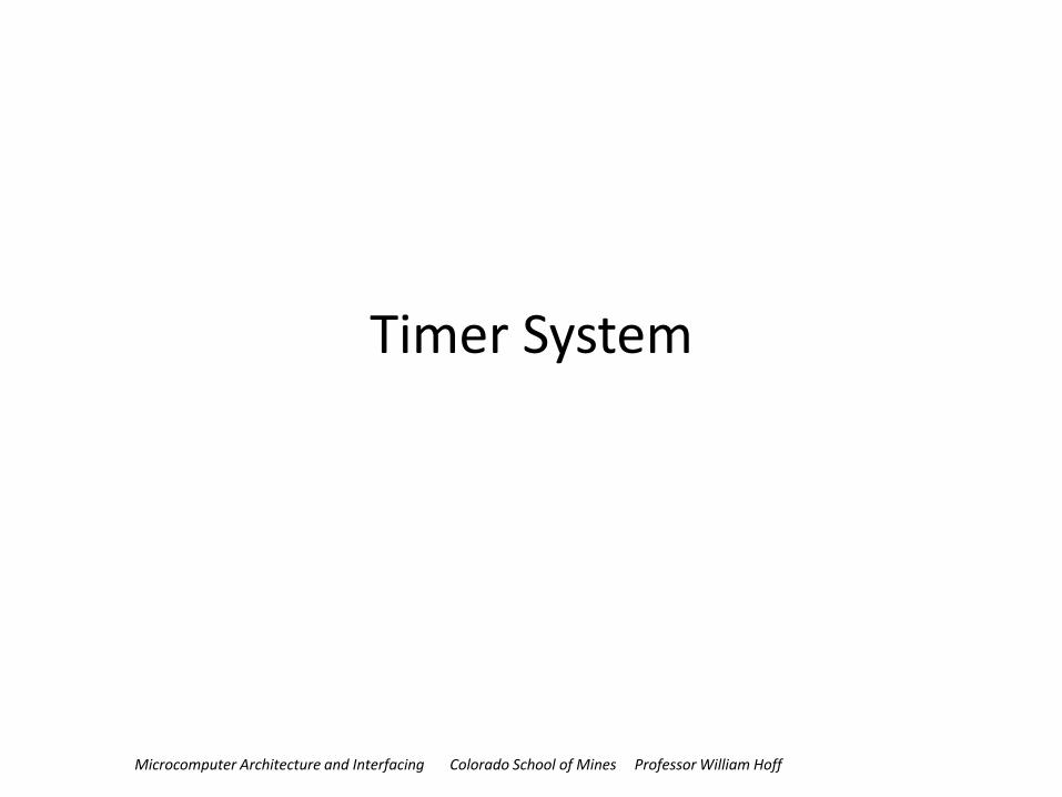
Timer System
• Just like the RTI system, we can make a timer out of a counter attached to the system clock
• But, unlike the RTI system, we will attach the counter to some additional hardware to do
– Accurate timing of input signals
– Accurate generation of output signals
• The timer system (counter + additional hardware) is very flexible and very accurate.
• First, let’s look at the counter portion.
2
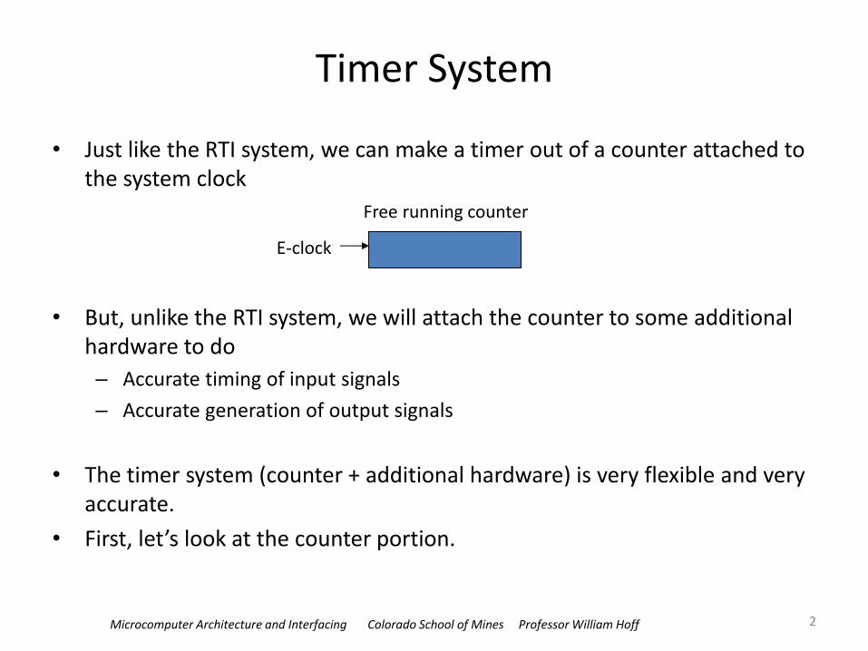
Free running counter
E-clock
Microcomputer Architecture and Interfacing Colorado School of Mines Professor William Hoff
Free running counter
• The free running counter is a 16-bit register called “TCNT”
• Just as in the RTI system, the counter sets a flag (and can cause an interrupt) when it overflows
3
E-clock
‘TSCR1’
TEN
PR2 PR1 PR0
‘TSCR2’ ‘TCNT’
16 bit counter TOF
‘TFLG2’
TOI
‘TSCR2’
I
‘CCR’
Timer overflow interrupt request
You can prescale the clock to reduce the clock rate
The counter is the TCNT register (it is read-only)
Set the TEN bit in the TSCR1 register to enable the timer to count up
max count is (216-1) = 65535

Microcomputer Architecture and Interfacing Colorado School of Mines Professor William Hoff
Registers associated with free running counter
• Make TEN = 1 to enable timer • Set the rate using PR2:PR0 • Detect overflows with TOF • Enable interrupts using TOI
4
Register Bit 7 Bit 6 Bit 5 Bit 4 Bit 3 Bit 2 Bit 1 Bit 0
TSCR1 TEN TSWAI TSFRZ TFFCA 0 0 0 0
TSCR2 TOI 0 0 0 TCRE PR2 PR1 PR0
TFLG2 TOF 0 0 0 0 0 0 0
PR2 PR1 PR0 Prescale Factor
0
0
0
0
1
1
1
1
0
0
1
1
0
0
1
1
0
1
0
1
0
1
0
1
1
2
4
8
16
32
64
128
Table 8.1 Timer counter prescale factor

Microcomputer Architecture and Interfacing Colorado School of Mines Professor William Hoff
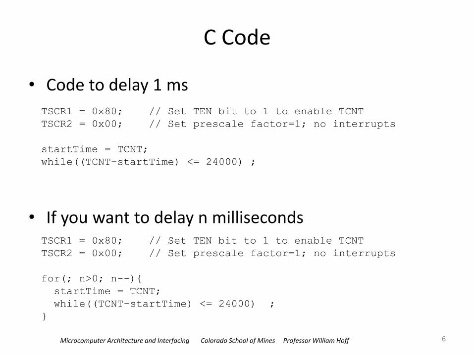
Example
• Use the free-running counter (TCNT) to time a delay of 1 ms – We’ll set the prescalar factor = 1, so that counter runs at the fastest
rate
– Then one count is 1/24 MHz = 41.6 ns
• The number of counts in 1 ms is: (10-3)/(1/24000000) = 24000
• Procedure – Get current value of TCNT, store into a variable startTime
– Keep testing the value of TCNT-startTime until it is greater than 24000
5
Microcomputer Architecture and Interfacing Colorado School of Mines Professor William Hoff
C Code
• Code to delay 1 ms
• If you want to delay n milliseconds
6
TSCR1 = 0x80; // Set TEN bit to 1 to enable TCNT
TSCR2 = 0x00; // Set prescale factor=1; no interrupts
startTime = TCNT;
while((TCNT-startTime) <= 24000) ;
TSCR1 = 0x80; // Set TEN bit to 1 to enable TCNT
TSCR2 = 0x00; // Set prescale factor=1; no interrupts
for(; n>0; n--){
startTime = TCNT;
while((TCNT-startTime) <= 24000) ;
}
Microcomputer Architecture and Interfacing Colorado School of Mines Professor William Hoff
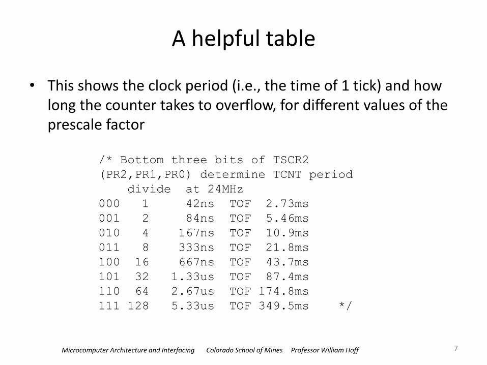
A helpful table
• This shows the clock period (i.e., the time of 1 tick) and how long the counter takes to overflow, for different values of the prescale factor
7
/* Bottom three bits of TSCR2
(PR2,PR1,PR0) determine TCNT period
divide at 24MHz
000 1 42ns TOF 2.73ms
001 2 84ns TOF 5.46ms
010 4 167ns TOF 10.9ms
011 8 333ns TOF 21.8ms
100 16 667ns TOF 43.7ms
101 32 1.33us TOF 87.4ms
110 64 2.67us TOF 174.8ms
111 128 5.33us TOF 349.5ms */
Microcomputer Architecture and Interfacing Colorado School of Mines Professor William Hoff
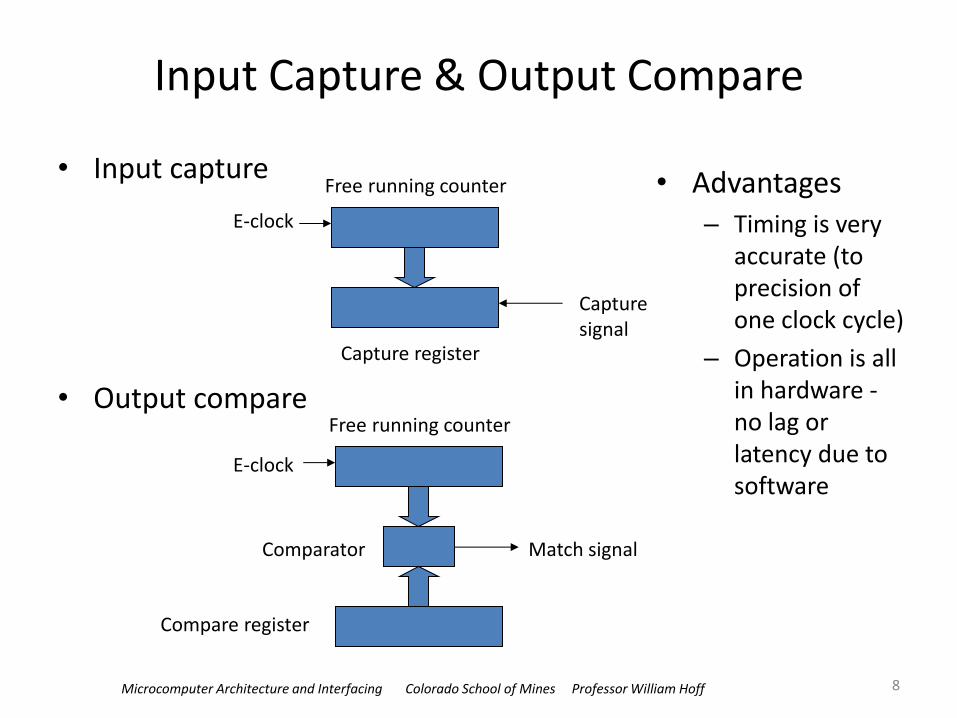
• Input capture
• Output compare
Input Capture & Output Compare
8
Free running counter
Capture register
E-clock
Capture signal
Free running counter
Compare register
E-clock
Match signal Comparator
• Advantages – Timing is very
accurate (to precision of one clock cycle)
– Operation is all in hardware - no lag or latency due to software
Microcomputer Architecture and Interfacing Colorado School of Mines Professor William Hoff
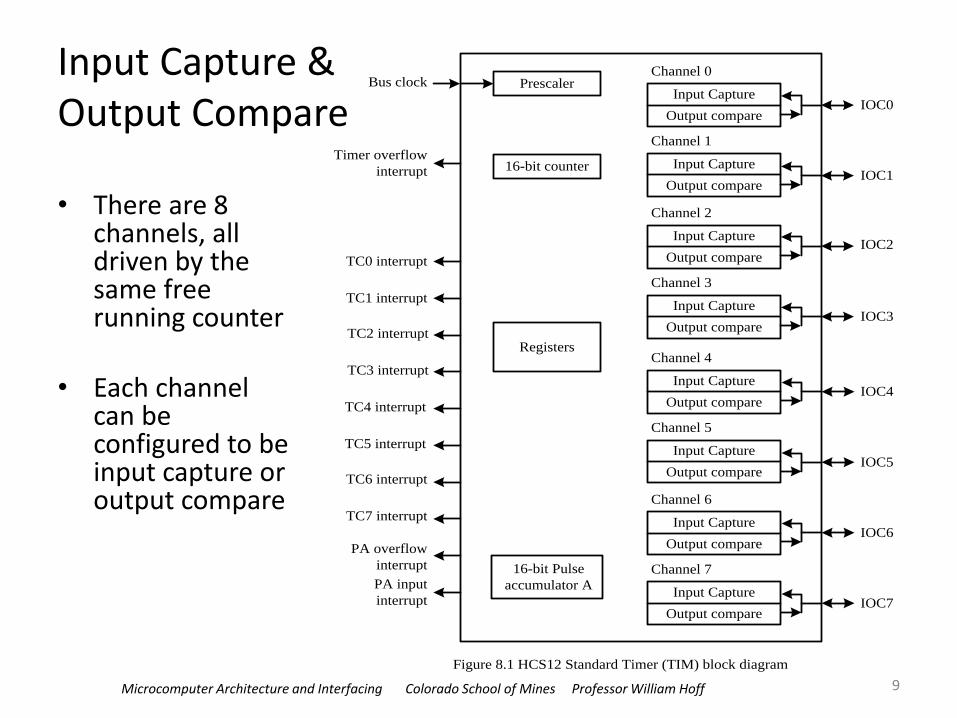
Input Capture & Output Compare
• There are 8 channels, all driven by the same free running counter
• Each channel can be configured to be input capture or output compare
9
Prescaler
16-bit counter
Input Capture
Output compare
Channel 0
Input Capture
Output compare
Channel 1
Input Capture
Output compare
Channel 2
Input Capture
Output compare
Channel 3
Input Capture
Output compare
Channel 4
Input Capture
Output compare
Channel 5
Input Capture
Output compare
Channel 6
Input Capture
Output compare
Channel 7
Registers
16-bit Pulse
accumulator A
IOC0
IOC1
IOC2
IOC3
IOC4
IOC5
IOC6
IOC7
Bus clock
Timer overflow
interrupt
TC0 interrupt
TC1 interrupt
TC2 interrupt
TC3 interrupt
TC4 interrupt
TC5 interrupt
TC6 interrupt
TC7 interrupt
PA overflow
interrupt
PA input
interrupt
Figure 8.1 HCS12 Standard Timer (TIM) block diagram
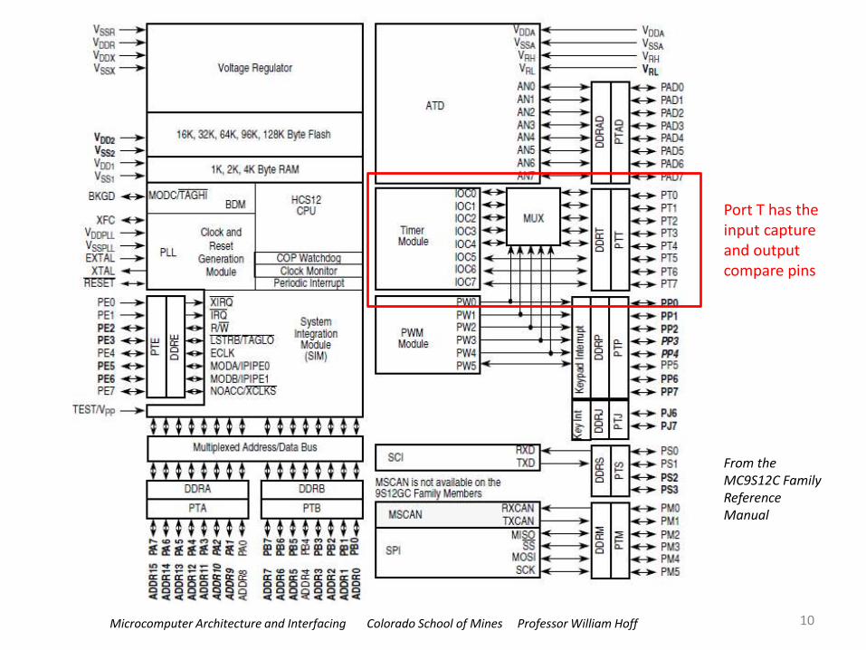
Microcomputer Architecture and Interfacing Colorado School of Mines Professor William Hoff
10
Port T has the input capture and output compare pins
From the MC9S12C Family Reference Manual
Microcomputer Architecture and Interfacing Colorado School of Mines Professor William Hoff
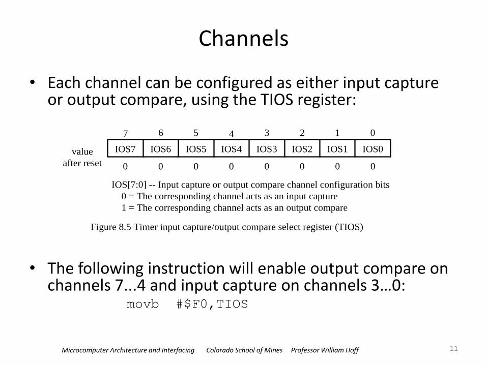
Channels
• Each channel can be configured as either input capture or output compare, using the TIOS register:
• The following instruction will enable output compare on channels 7...4 and input capture on channels 3…0:
movb #$F0,TIOS
11
7 6 5 4 3 2 1 0
IOS7 IOS6 IOS5 IOS4 IOS3 IOS2 IOS1 IOS0value
after reset 0 0 0 0 0 0 0 0
Figure 8.5 Timer input capture/output compare select register (TIOS)
IOS[7:0] -- Input capture or output compare channel configuration bits
0 = The corresponding channel acts as an input capture
1 = The corresponding channel acts as an output compare

Microcomputer Architecture and Interfacing Colorado School of Mines Professor William Hoff
Input Capture
• Automatically captures (latches) the time when a signal is input – Value is stored in a capture register called TCn (n=0..7)
– Program can read time later
– Sets a flag (CnF) when transition occurs (n=0..7) in register TFLG1:
12
7 6 5 4 3 2 1 0
C7F C6F C5F C4F C3F C2F C1F C0F
reset: 0 0 0 0 0 0 0 0
Figure 8.8 Timer interrupt flag register 1 (TFLG1)
CnF: input capture/output compare interrupt flag bits
0 = interrupt condition has not occurred
1 = interrupt condition has occurred
Microcomputer Architecture and Interfacing Colorado School of Mines Professor William Hoff
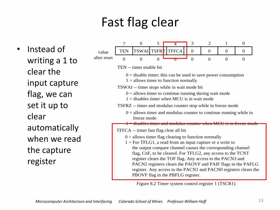
Fast flag clear
• Instead of writing a 1 to clear the input capture flag, we can set it up to clear automatically when we read the capture register
13
7 6 5 4 3 2 1 0
TEN TSWAI TSFRZ TFFCA 0 0 0 0value
after reset 0 0 0 0 0 0 0 0
TEN -- timer enable bit
0 = disable timer; this can be used to save power consumption
1 = allows timer to function normally
TSWAI -- timer stops while in wait mode bit
0 = allows timer to continue running during wait mode
1 = disables timer when MCU is in wait mode
TSFRZ -- timer and modulus counter stop while in freeze mode
0 = allows timer and modulus counter to continue running while in
freeze mode
1 = disables timer and modulus counter when MCU is in freeze mode
TFFCA -- timer fast flag clear all bit
0 = allows timer flag clearing to function normally
1 = For TFLG1, a read from an input capture or a write to
the output compare channel causes the corresponding channel
flag, CnF, to be cleared. For TFLG2, any access to the TCNT
register clears the TOF flag. Any access to the PACN3 and
PACN2 registers clears the PAOVF and PAIF flags in the PAFLG
register. Any access to the PACN1 and PACN0 registers clears the
PBOVF flag in the PBFLG register.
Figure 8.2 Timer system control register 1 (TSCR1)
Microcomputer Architecture and Interfacing Colorado School of Mines Professor William Hoff
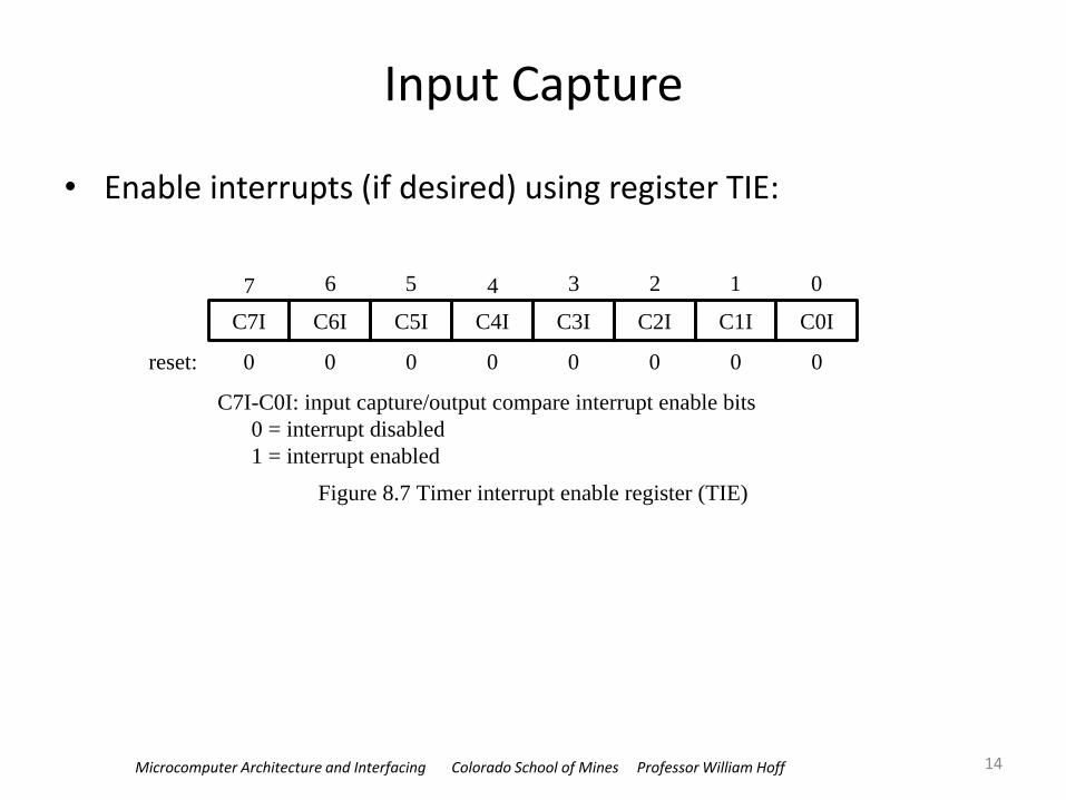
Input Capture
• Enable interrupts (if desired) using register TIE:
14
7 6 5 4 3 2 1 0
C7I C6I C5I C4I C3I C2I C1I C0I
reset: 0 0 0 0 0 0 0 0
Figure 8.7 Timer interrupt enable register (TIE)
C7I-C0I: input capture/output compare interrupt enable bits
0 = interrupt disabled
1 = interrupt enabled

Microcomputer Architecture and Interfacing Colorado School of Mines Professor William Hoff
Input Capture
• You can specify what signal edge to capture
• Registers TCTL3 and TCTL4):
15
7 6 5 4 3 2 1 0
EDG7B EDG7A EDG6B EDG6A EDG5B EDG5A EDG4B EDG4Avalue
after reset 0 0 0 0 0 0 0 0
Figure 8.5 Timer control register 3 and 4
7 6 5 4 3 2 1 0
EDG3B EDG3A EDG2B EDG2A EDG1B EDG1A EDG0B EDG0A
0 0 0 0 0 0 0 0
(a) Timer control register 3 (TCTL3)
(b) Timer control register 4 (TCTL4)
EDGnB EDGnA -- Edge configuration
0 0 : Capture disabled
0 1 : Capture on rising edges only
1 0 : Capture on falling edges only
1 1 : Capture on both edges
Rising edge Falling edge
or
Figure 8.4 Events represented by signal edges
Microcomputer Architecture and Interfacing Colorado School of Mines Professor William Hoff
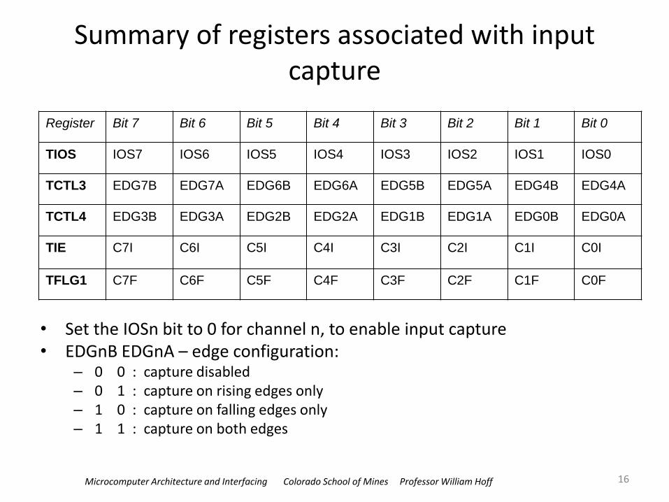
Summary of registers associated with input capture
• Set the IOSn bit to 0 for channel n, to enable input capture • EDGnB EDGnA – edge configuration:
– 0 0 : capture disabled – 0 1 : capture on rising edges only – 1 0 : capture on falling edges only – 1 1 : capture on both edges
16
Register Bit 7 Bit 6 Bit 5 Bit 4 Bit 3 Bit 2 Bit 1 Bit 0
TIOS IOS7 IOS6 IOS5 IOS4 IOS3 IOS2 IOS1 IOS0
TCTL3 EDG7B EDG7A EDG6B EDG6A EDG5B EDG5A EDG4B EDG4A
TCTL4 EDG3B EDG3A EDG2B EDG2A EDG1B EDG1A EDG0B EDG0A
TIE C7I C6I C5I C4I C3I C2I C1I C0I
TFLG1 C7F C6F C5F C4F C3F C2F C1F C0F
Microcomputer Architecture and Interfacing Colorado School of Mines Professor William Hoff
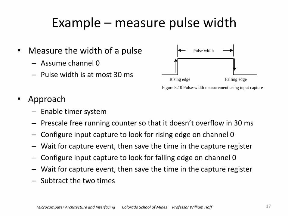
Example – measure pulse width
• Measure the width of a pulse – Assume channel 0
– Pulse width is at most 30 ms
• Approach – Enable timer system
– Prescale free running counter so that it doesn’t overflow in 30 ms
– Configure input capture to look for rising edge on channel 0
– Wait for capture event, then save the time in the capture register
– Configure input capture to look for falling edge on channel 0
– Wait for capture event, then save the time in the capture register
– Subtract the two times
17
Pulse width
Rising edge Falling edge
Figure 8.10 Pulse-width measurement using input capture
Microcomputer Architecture and Interfacing Colorado School of Mines Professor William Hoff
Details of approach • Enable timer system
• Prescale free running counter so that it doesn’t overflow in 30 ms
• Configure input capture to look for rising edge on channel 0
• Wait for capture event, then save the time in the capture register
• Configure input capture to look for falling edge on channel 0
• Wait for capture event, then save the time in the capture register
• Subtract the two times
18
Microcomputer Architecture and Interfacing Colorado School of Mines Professor William Hoff 19
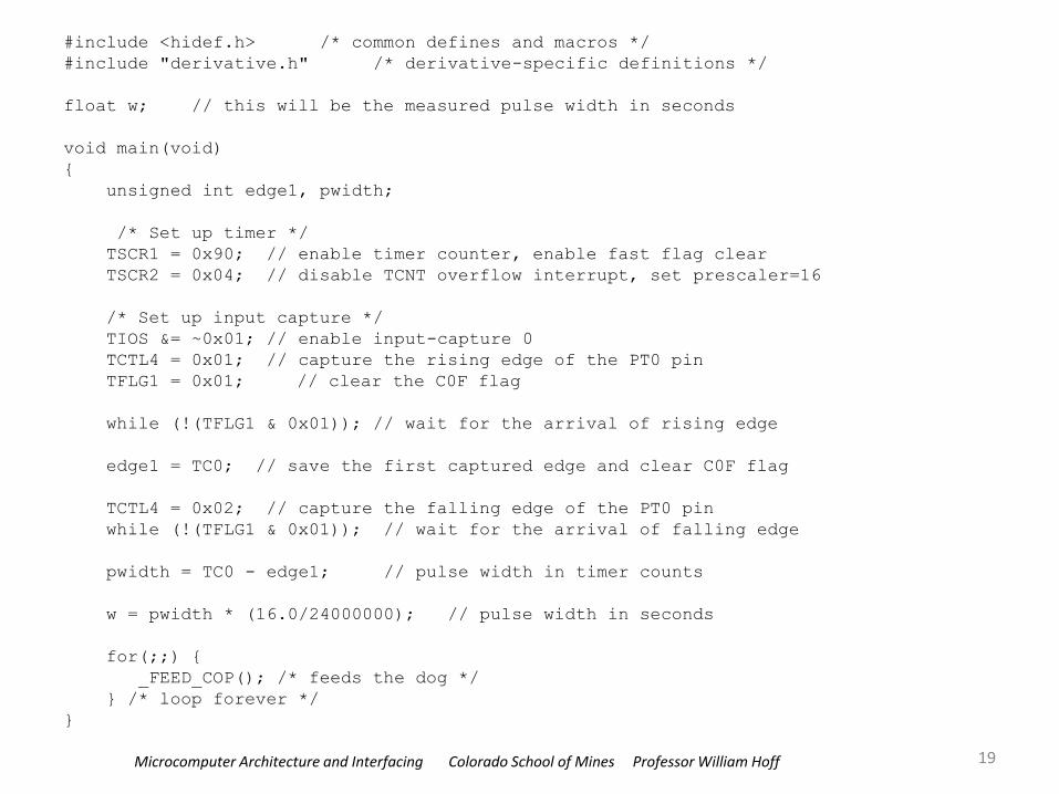
#include <hidef.h> /* common defines and macros */
#include "derivative.h" /* derivative-specific definitions */
float w; // this will be the measured pulse width in seconds
void main(void)
{
unsigned int edge1, pwidth;
/* Set up timer */
TSCR1 = 0x90; // enable timer counter, enable fast flag clear
TSCR2 = 0x04; // disable TCNT overflow interrupt, set prescaler=16
/* Set up input capture */
TIOS &= ~0x01; // enable input-capture 0
TCTL4 = 0x01; // capture the rising edge of the PT0 pin
TFLG1 = 0x01; // clear the C0F flag
while (!(TFLG1 & 0x01)); // wait for the arrival of rising edge
edge1 = TC0; // save the first captured edge and clear C0F flag
TCTL4 = 0x02; // capture the falling edge of the PT0 pin
while (!(TFLG1 & 0x01)); // wait for the arrival of falling edge
pwidth = TC0 - edge1; // pulse width in timer counts
w = pwidth * (16.0/24000000); // pulse width in seconds
for(;;) {
_FEED_COP(); /* feeds the dog */
} /* loop forever */
}
Microcomputer Architecture and Interfacing Colorado School of Mines Professor William Hoff
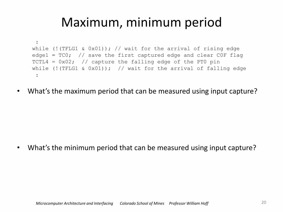
Maximum, minimum period
• What’s the maximum period that can be measured using input capture?
• What’s the minimum period that can be measured using input capture?
20
:
while (!(TFLG1 & 0x01)); // wait for the arrival of rising edge
edge1 = TC0; // save the first captured edge and clear C0F flag
TCTL4 = 0x02; // capture the falling edge of the PT0 pin
while (!(TFLG1 & 0x01)); // wait for the arrival of falling edge
:
Microcomputer Architecture and Interfacing Colorado School of Mines Professor William Hoff
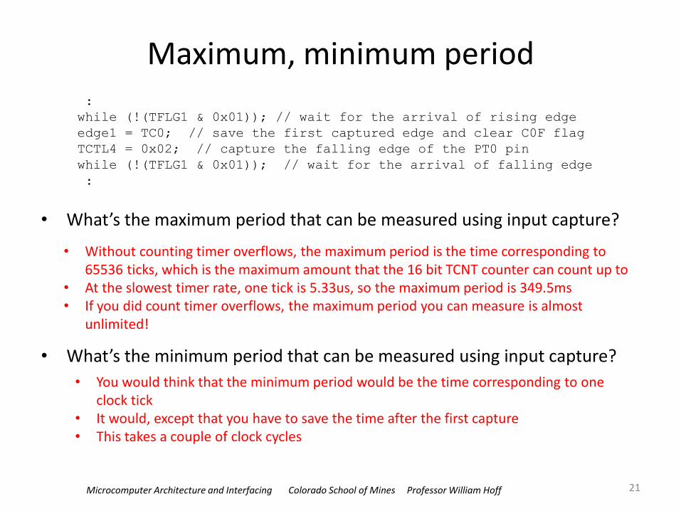
Maximum, minimum period
• What’s the maximum period that can be measured using input capture?
• What’s the minimum period that can be measured using input capture?
21
• Without counting timer overflows, the maximum period is the time corresponding to 65536 ticks, which is the maximum amount that the 16 bit TCNT counter can count up to
• At the slowest timer rate, one tick is 5.33us, so the maximum period is 349.5ms • If you did count timer overflows, the maximum period you can measure is almost
unlimited!
• You would think that the minimum period would be the time corresponding to one clock tick
• It would, except that you have to save the time after the first capture • This takes a couple of clock cycles
:
while (!(TFLG1 & 0x01)); // wait for the arrival of rising edge
edge1 = TC0; // save the first captured edge and clear C0F flag
TCTL4 = 0x02; // capture the falling edge of the PT0 pin
while (!(TFLG1 & 0x01)); // wait for the arrival of falling edge
:
Microcomputer Architecture and Interfacing Colorado School of Mines Professor William Hoff
Summary
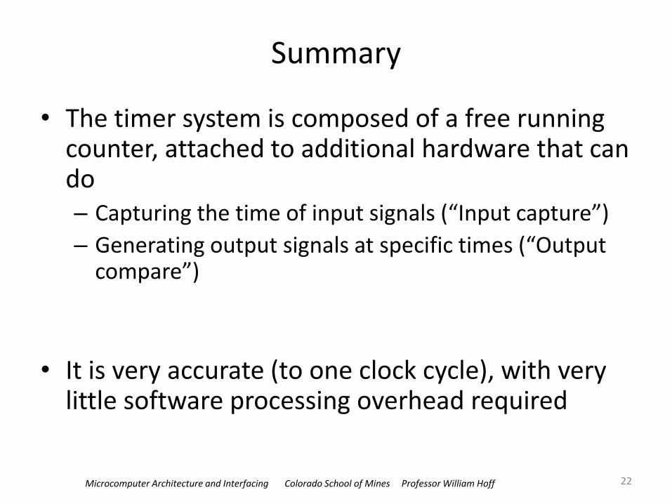
• The timer system is composed of a free running counter, attached to additional hardware that can do – Capturing the time of input signals (“Input capture”)
– Generating output signals at specific times (“Output compare”)
• It is very accurate (to one clock cycle), with very little software processing overhead required
22