
Introduction to Mechatronics - WordPress.com · 2018-02-16 · MEASUREMENET CHARACTERISTICS...
34
1 UNIT –I Introduction to Sensors & Actuators Mr Manoj J Rajale
Transcript of Introduction to Mechatronics - WordPress.com · 2018-02-16 · MEASUREMENET CHARACTERISTICS...

1
UNIT –I
Introduction to Sensors & Actuators
Mr Manoj J Rajale

MOTOR
Input,
Electrical Power
Output,
Rotaion
Not concentrate on what goes on inside
Concentrate only on output & Input device
Measurement system?
MeasuringInput quantity
Output
the value
of quantity
Measurement
System
ThermometerInput Temp.Output
number on scale 2

MEASUREMENET CHARACTERISTICS
•Shows the performance of instruments to be used.
•Divided into two categories: static and dynamic characteristics.
A) Static characteristics-
Refer to the comparison between steady output and ideal output
when the input is constant.
Eg- Linearity, Sensitivity of measurement, Resolution, Threshold
B) Dynamic characteristics-
Refer to the comparison between instrument output and ideal
output when the input changes.
Eg- Frequency response/Bandwidth,Delay, Stability/undershoot
3

STATIC CHARACTERISTICS
1. ACCURACY-
is the closeness of a measurement (or a set of observations) to
the true value.
Higher the accuracy, lower the error
Accuracy is the ability of an instrument to show the exact
reading.
Always related to the extent of the wrong reading/non accuracy.
Normally shown in percentage of error which of the full scale
reading percentage.
4
E = measured value – true value
= system output – system input

5
Accuracy depends on inherent limitations of
instrument and shortcomings in measurement
process.

2. PRECISION
An equipment which is precise is not
necessarily accurate.
Defined as the capability of an instrument to
show the same reading when used each time
(reproducibility of the instrument).
6

7

3. RANGE & SPAN
a. Range The region between the limits within which an
instrument is designed to operate formeasuring, indicating or recording a physicalquantity is called the range of the instrument.
The range is expressed by stating the lower andupper values.
Range -100°C to 100°C
8

b. Span
Span represents the algebraic differences
between the upper and lower range values
of the instrument.
An instrument which has a reading range of
–100°C to 100 °C span is 200 °C.
9

10

4.Linearity
Most instruments are specified to function over a
particular range and the instruments can be said
to be linear when incremental changes in the
input and output are constant over the
specified range.
Linearity = maximum deviation from the
reading of x and the straight line.
11

12

5.Resolution/Discrimination-
The smallest change in input reading that
can be traced accurately.
Given in the form ‘% of full scale (% fs)’.
13

6.Sensitivity
This is the relationship between a change in the
output reading for a given change of the input.
(This relationship may be linear or non-linear.)
Sensitivity is often known as scale factor or
instrument magnification and an instrument with a
large sensitivity (scale factor) will indicate a large
movement of the indicator for a small input change.
14

Example of sensitivity
The resistance value of a Platinum Resistance
Thermometer changes when the temperature
increases. Therefore, the unit of sensitivity for this
equipment is Ohm/°C.
15
Most Sensitive
Variation of physical variables
Slope
=output/i
nput

Load
Cell
Force, F
Output, Vo
Output, Vo (V)
Input, Fi (kN)
Slope = 5
V/kN
Input, F(kN) K=5V/kN Output, Vo(V)
Example
16

7. DEAD ZONE
• Defined as the range of input reading when there isno change in output
(unresponsive system).
17
Dead Space
Output
Reading
Measured
Variables
- +

8.Threshold
If the instrument input is very gradually
increased from zero there will be a minimum
value required to give a detectable output
change. This minimum value defines the
threshold of the instrument.
input
Output
18

9.Hysteresis
19
Hysteresis exists not only
in magnetic circuits, but
in instruments also. For
example, the deflection of
a diaphragm type pressure
guage may be different for
the same pressure, but
one for increasing and
other for decreasing, as
shown in Fig.. The
hysteresis is expressed as
the maximum hysteresis as
a full scale
reading, i.e., referring fig.,
20
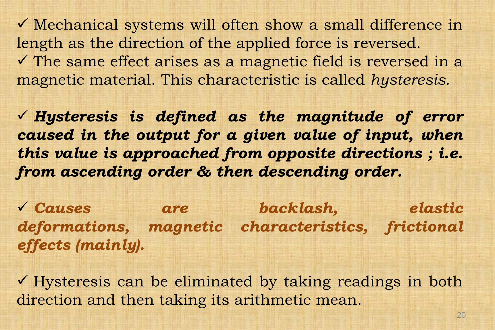
Mechanical systems will often show a small difference in
length as the direction of the applied force is reversed.
The same effect arises as a magnetic field is reversed in a
magnetic material. This characteristic is called hysteresis.
Hysteresis is defined as the magnitude of error
caused in the output for a given value of input, when
this value is approached from opposite directions ; i.e.
from ascending order & then descending order.
Causes are backlash, elastic
deformations, magnetic characteristics, frictional
effects (mainly).
Hysteresis can be eliminated by taking readings in both
direction and then taking its arithmetic mean.

10 .Drift-
Zero drift is variation in the output of an
instrument which is not caused by any change in
the input.
It is commonly caused by internal temperature
changes and component instability.
21

22
Effects of disturbance: (a) zero drift;
(b) sensitivity drift;
(c) zero drift plus sensitivity drift.

11.Reapatability
It is the ability of the measuring
instrument to give the same value every
time, the measurement of given quantity is
repeated, under the same conditions.
Repeatability refers to a sensor’s ability to
give identical outputs for the same input
Precision (or random) errors cause a lack
of repeatability
23

12. Backlash-
It is maximum distance or angle through
which any part of a mechanical system may
be moved in one direction without applying
appreciable force or motion to the next part
in mechanical sequence.
Can be minimized if components are made to
very close tolerances.
24

1.Speed of Response
It is defined as the rapidity with which an
instrument responds to a change in the
value of the quantity being measured.
B)Dynamic Characteristics
25

2.Fidelity
26
Fidelity of an instrumentation system is
defined as the degree of closeness with
which the system indicates or records the
signal which is impressed upon it.
It refers to the ability of the system to
reproduce the output in the same form as the
input.
Poor Fidelity indicates non linearity of
instrument
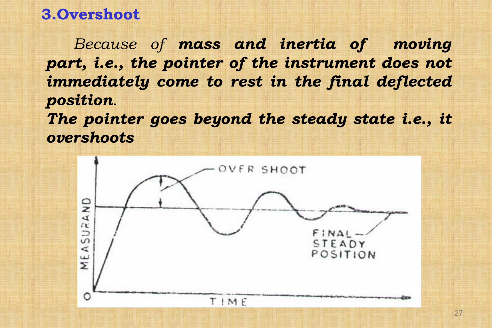
3.Overshoot
27
Because of mass and inertia of moving
part, i.e., the pointer of the instrument does not
immediately come to rest in the final deflected
position.
The pointer goes beyond the steady state i.e., it
overshoots

4.Dyanamic Error
28
The difference between the indicated quantity
and the true value of the time varying quantity is
the dynamic error, here static error of the instrument
is assumed to be zero.

Error
Error is the difference between the true
value of the size being measured and the
value found by measurement.
Measurement & Control
29

Measurement Error
30
1.Static Error
E=Vm Vt1.Measured Value
2.True Value
2.Relative Error
Error =Vm Vt
VtX 100

Sources of Error
1.Defect in instrument.
2.Adjustment of an instrument.
3.Imperfection in design of instrument.
4.Method of location.
5.Environmental effects.
6.Error due to properties of object.
7. Error due to surface finish of object.
8.Observational error.
31

1. Gross errors.
32
These are basically human errors caused
by the operator or person using the
instrument.
The instrument may be good and may not give
any error but still the measurement may go
wrong due to the operator.
Types of Errors
1.Gross errors.
2.Systematic errors.
3.Random errors.

1. Observational errors.
2. Reading with parallax error.
3. Incorrect adjustments of zero and full-scale
adjustments.
4. Improper applications of instruments:
Using a 0–100 V voltmeter
to measure 0.1 V, etc.
5.Operational error.
33

2.Systematic Errors
34
These are divided into two categories:
1)Instrumental errors: Due to shortcomings of
the instruments.
2)Environmental errors: Due to external
conditions affecting the instrument.


