Introduction to mainframe_operating_system
67
© 2011 IBM Corporation Esra Ufacık, Mainframe Client Technical Specialist, IBM Turk, [email protected] Introduction to Mainframe Operating System
-
Upload
esra-ufacik -
Category
Technology
-
view
55 -
download
0
Transcript of Introduction to mainframe_operating_system

© 2011 IBM Corporation
Esra Ufacık, Mainframe Client Technical Specialist, IBM Turk, [email protected]
Introduction to Mainframe Operating System

2
Agenda
�Introduction to z/OS�z/OS System Programming�Mainframe Clustering Technology�Continuous Availability

3
Mainframe Operating System Heritage
� OS/360 -> OS/VS -> MVS -> MVS/SP -> MVS/XA -> MVS/ESA -> OS/390 -> z/OSz/OS, IBM’s premier zSeries operating system, is a highly secure, scalable, high-performance enterprise operating system on which to build and deploy traditional and Java-enabled applications, providing a comprehensive and diverse application execution environment.
� DOS/360 -> DOS/VS -> VSE/SP -> VSE/ESA -> z/VSE z/VSE enables proven, robust, and cost-effective solutions. z/VSE provides sturdy batch and industrial strength on-line transaction processing (CICS) capabilities. z/VSE can fit comfortably into a legacy of thrifty, dependable z/VSE solutions.
� ACP -> TPF-> z/TPFTPF is the platform driving the business-critical systems for many of IBM's largest and most sophisticated users of online transactionprocessing - airlines, railroads, hotels, financial services, government, credit card and banking industries.
� CP/67 -> VM/370 -> VM/SP -> VM/XA -> VM/ESA -> z/VMz/VM provides a highly flexible test and production environment for enterprises deploying the latest e-business solutions. z/VM helps enterprises meet their growing demands for multi-user server solutions with support for a broad range of operating systems.

4
INTRODUCTION TOz/OS

5
z/OS Innovation – Redefining the mainframe for 6 decades!
S/360zSeries, System zS/390®S/370™ zEnterprise
1960s
Models 40,
50, 65, 90,
91
3195
1970s
3145 3158 3031 3032
3155 3168 3033
3081,3083, 3090
3084ES/9000®
1980s
G4, G5, G6
1990s
z900 z990
2000s
z196 & zBX
OS/360 MFT
24-bit
RTM
OS/VS1
OS/VS2
QSAM
BDAMSVS
MVT MVS
TSO
ISPF
JES2
JES3
IPO
ACRFRRsVTAM
Cross-memory
RACF
2010s
MVS/XA MVS/ESA
OMVS
31-bit
SMSPR/SM
ISMF
CBIPODFP
PDSE
LLA
HiperspaceEMIF
Parallel Sysplex
OS/390
USS
WLM
ServerPac
ESCON
z/OS & Linux*
64-bit
IRD GDPSzAAP zIIPS
HiperSocketsCUOD HyperswapFlashCopy
FICON
IMS CICS NCP DB2 HTTP Websphere
Assembler
COBOL
C C++
Application investment protection
z800 z890z9-109z9EC/BC
z10EC/BC
SAPsz/FS
Unicode
* Provided new z/OS interfaces
Hiperdispatch
MIDAW
CP Sub-Capping
IFB
OSMF
OSA-Express3
PFA
EAVs
RTD
JAVA J2EE
XML
HTML
MLS

6
Typical mainframe workloads
Batch job
Application Program
Output Data
Application Program
Input
Data
Process data to perform a
particular task
Online (real time) transaction
Query
Reply
Access shared data on behalf of
online user

7
Typical batch use
Disk Storagedatabases
Tape Storage
Sequential data sets
Partners and clients exchange
information
Reports
Backups
Data update
Reports
Statistics, summaries, exceptions
ResidenceMain office
Branch offices
Account balances bills, etc
Processingreports
MainframeProcessing batch jobs
44
55
Reports
22
1010
11
88
66
33
CREDIT CARD
1234 5678 90121234 5678 9012VALID FROM GOOD THRU
XX/XX/XX XX/XX/XX
PAUL FISCHER
XX/XX/XX XX/XX/XX
PAUL FISCHER
77
99
SystemOperator
ProductionControl

8
Typical online use
Disk storage
controller
Stores database
files
queries and
updates
Account activities
Officeautomation
systems
Mainframe
Accessesdatabase
Requests
ATMs
Branch
offices
Business analysts Inventory control
Branch office automation systems
Network
(e.g. TCP/IP or SNA)
55
66
33
22
44
11
Central office

9
Roles in the mainframe world
Operator
Production Control Analyst
System AdministratorSystem Programmer
End User
ApplicationDeveloper
RolesRoles

10
What is z/OS?
� The most widely used mainframe operating system– 64-bit operating system
� Ideally suited for processing large workloads for many concurrent users
� Designed for:– Serving 1000s of users concurrently– I/O and numeric intensive computing – Processing very large heterogeneous workloads– Running mission critical applications securely

11
Hardware resources managed by z/OS
... Director links mainframes with DASD controllers
System Console(hardware)
Master Console(z/OS)
Operator Console(z/OS)
Mainframe computer(CPU, processor
storage)
Disk storage (DASD volumes)
DASD
controller
Tape drive
Tape cartridges
z/OS runshere
12
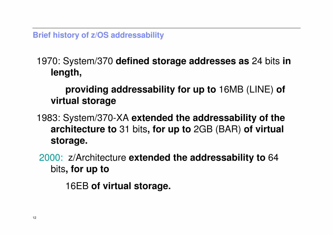
Brief history of z/OS addressability
1970: System/370 defined storage addresses as 24 bits in length,
providing addressability for up to 16MB (LINE) of virtual storage
1983: System/370-XA extended the addressability of the architecture to 31 bits, for up to 2GB (BAR) of virtual storage.
2000: z/Architecture extended the addressability to 64 bits, for up to
16EB of virtual storage.

13
z/OS SYSTEMPROGRAMMING

14
What is systems programming?
�A systems programmer installs, customizes and maintains the operating system
�To do this they need knowledge of–Hardware
• Storage• Processor
–Software• System libraries and data sets
–Current customization

15
System performance and workload management
z/OS new featuresimplementation and z/OS system
maintenance
Controlling operatingactivities and functions
System parameters and system
librariesmanagement
SYSTEM PROGRAMMING
Security, Availability and Integrity
Hardware I/Oconfiguration
iodfxxiodfxx
System programming overview

16
z/OS operational system administration is:
�Software installation and maintenance
�Customize parameters
�System libraries for software
�System data sets
�z/OS system address spaces and subsystems
�Real and virtual storage

17
z/OS Workload Manager
�Workload manager (WLM) is an address space which manages the tasks running on the system
�Uses an installation-defined policy to determine relative priority of competing workloads
�WLM can also be used to manage hardware resources

18
System performance
�System tuning is constant and iterative
�Only a real problem when resources are constrained
�WLM is one component
�Can only manage what is set up
� Initial set up of initiators and other resources plays a great part

19
Fundamental Components of Workload Capacity Performance
� Instruction Path Length for a transaction or job– Application dependent, of course– But can also be sensitive to N-way (due to MP effects such as locking, work queue searches, etc)
� Instruction Complexity (Micro processor design)– Many design alternatives
• Cycle time (GHz), instruction architecture, pipeline, superscalar, Out-Of-Order, branch prediction and more
– Workload effect• May be different with each processor design• But once established for a workload on a processor, doesn’t change very much
� Memory Hierarchy or “Nest”– Many design alternatives
• cache (levels, size, private, shared, latency, MESI protocol), controller, data buses
– Workload effect• Quite variable• Sensitive to many factors: locality of reference, dispatch rate, IO rate, competition with other applications and/or
LPARs, and more• Net effect of these factors represented in “Relative Nest Intensity”
– Relative Nest Intensity• Activity beyond processor-chip cache(s) is the most sensitive area• Reflects activity distribution and latency to book-level caches and memory• Level 1 cache miss percentage also important• Data for calculation available from CPU MF (SMF 113) starting with z10

20
Job flow
� Job entry subsystem (JES) controls job flow
� Receives jobs into system
� Initiates the job
� Controls initial output processing

21
I/O device management
� Input/output device configuration must be defined to both hardware and software
�HCD is used to build an I/O definition file
�This definition can be activated to both software and hardware dynamically
�Sometimes major changes require an IPL of software or POR of hardware

22
Security
�Protection of data against unauthorized disclosure, transfer, modification or destruction
�Systems programmer installs and maintains the security system

23
Integrity
�Designed, implemented and maintained to protect against unauthorized access
�Unauthorized software must not be able to access authorized states
�Unauthorized software must not be able to bypass system security such as RACF

24
Availability
�System availability is designed to be very high
�Many systems require 24 hour 7 day operation

25
Change control
� I/T organizations achieve their goals through disciplined change management processes and policy enforcement
�These goals include:–High service availability–Increased security–Audit readiness–Cost savings

26
z/OS operation
�This is the day to day management of the operating environment both software and hardware
�Operator interaction is message and command based
�Automated processing of the messages and commands is available and operators now manage by exception

27
z/OS Production Control
�Build batch schedules
�Promote programs to production
� Investigate batch failures

28
MAINFRAME CLUSTERINGTECHNOLOGY

29
Clustering
� Clustering has been done for many years in several forms– Basic shared DASD– CTC/GRS rings– Basic and Parallel sysplex
� Image is used to describe a single z/OS system, which might be standalone or an LPAR on a large box

30
Basic shared DASD
� Limited capability
� Reserve and release against a whole disk
� Limits access to that disk for the duration of the update

31
Basic Sysplex
� Global Resource Sharing (GRS) used to pass information between systems via the Channel-To-Channel ring
� Request ENQueue on a dataset, update, the DEQueue
� Loosely coupled system

32
Parallel Sysplex
� This extension of the CTC ring uses a dedicated Coupling Facility to store ENQ data for GRS
� This is much faster
� The CF can also be used to share application data such as DB2 tables
� Can appear as a single system
zSeries ( or LPAR)
z/OS
channels
zSeries ( or LPAR)
z/OS
channels
control unit control unit
system or LPAR
Coupling
Facility
CF channels

33
Sysplex hardware overview

34
Time-of-Day clock
� There is a longstanding requirement for accurate time and date information in data processing. As single operating systems have been replaced by multiple, coupled operating systems on multiple servers, this need has evolved into a requirement for both accurate and consistent clocks among these systems. Server Time Protocol is a server-wide facility, implemented in the Mainframe microcode, designed to provide the capability of time synchronization between the latest Mainframe machines
� STP is designed for servers that are configured in a Parallel Sysplex or a standard sysplex without a Coupling Facility, as well as servers that are not in a sysplex but need to be time-synchronized. STP supports a multi-site timing network of up to 100 Km (62 miles) over fiber optic cabling. STP is a message-based protocol in which timekeeping information is passed over data links between servers. The timekeeping information is transmitted over externally defined coupling links.

35
� Dynamically balances workload across systems with high performance
� Improve availability for both planned and unplanned outages
� Provide for system or application rolling-maintenance
� Offer scalable workload growth both vertically and horizontally
� View multiple-system environments as a single logical resource
� Use special server time protocol (STP) to sequence events between servers
Parallel Sysplex Attributes

36
While a basic sysplex is an actual entity, with a defined name (the sysplexname), a parallel sysplex is more conceptual, that is a set of systems within a sysplex that all have access to the same one or more coupling facilities*.
* Described later in slides
Basic v.s. Parallel Sysplex (SYStems comPLEX)
� September 1990, IBM debuted the SYSPLEX introducing XCF services allowing
authorized applications to communicate with applications on the same or other
systems using specialized links.
� BASIC – A shared couple data set used between all the images holds control
information and provides a mechanism for monitoring the status of the images
� Parallel – This enhanced sysplex implementation provided the capability to use a
specialized LIC operating environment called the coupling facility control code
(CFCC) offering speed and integrity to shared data.

37
SYStems comPLEX or SYSPLEX

38
Sysplex Goal is a Single System Image

39
What a Sysplex can do for YOU…
� It will address any of the following types of work:–Large business problems that involve hundreds of end users, or deal with
volumes of work that can be counted in millions of transactions per day.
–Work that consists of small work units, such as online transactions, or large work units that can be subdivided into smaller work units, such as
queries.–Concurrent applications on different systems that need to directly access
and update a single database without jeopardizing data integrity and security.
� Provides reduced cost through:–Cost effective processor technology
–Software licensing charges in Parallel Sysplex
–Continued use of large-system data processing skills without re-education–Protection of z/OS application investments
–The ability to manage a large number of systems more easily than other comparably performing multisystem environments

40
What else a Sysplex can do for YOU !
� Platform for continuous availability so that applications can beavailable 24 hours a day, 7 days a week, 365 days a year
� Ability to do more work�Greater capacity�Improved ability to manage response time�Platform for further capacity and response time advances
� Greater flexibility�Ability to mix levels of hardware and software�Ability to dynamically add systems�An easy path for incremental growth�Varied platforms for applications, including parallel, open, and
client/server
� Workload balancing

41
Sysplex Anatomy
A sysplex can include the following software and hardware:
1. z/OS Products include the cross-system coupling facility (XCF) component, which enables
authorized programs in a sysplex to communicate with programs on the same MVS system
or other MVS systems and the GRS (global resource serialization) component, which
serializes sysplex resources.
2. Signaling paths between z/OS systems
– There must be at least two operational signaling paths (one inbound and one outbound
path) between each of the zOS systems
– The signaling paths can be defined through:
• Coupling facility list structures
• ESCON or FICON channels operating in CTC mode
• 3088 Multisystem Channel Communication Unit
3. Sysplex couple data set z/OS requires a DASD data set
– Shared by all systems in the sysplex.
– Sysplex couple data set, z/OS stores information related to the sysplex, systems, XCF
groups*, and their members.
ŦAn XCF group is the set of related members that a multisystem application defines to XCF. A multisystem application can be an installation-defined program, an zOS component or subsystem, or a program product.
However, you can define a single system sysplex that does not require a sysplex couple data set.
CF

42
The extended clock format was required to provide the improved resolution necessary for the faster z10 processors as they become available. The extended time-of-day architecture ensures that when an application in a multisystemsysplex environment requests a TOD value, XCF will always return a clock value that is unique across the sysplex, regardless of the number of systemsin the sysplex.
Sysplex Anatomy… continued
4. Common time reference
When the sysplex consists of multiple zOS systems running two or more processors, zOS
requires that the processors be connected to the same Sysplex Timer.
– zOS uses the Sysplex Timer to synchronize TOD clocks across systems.
– For a multisystem sysplex defined on a single processor (under PR/SM™ or VM) the
SIMETRID parameter in the CLOCKxx parmlib member must specify the simulated
Sysplex Timer identifier to synchronize timings for the zOS systems.
TOD Clocks: In a configuration with more than one CP, each CP may have a separate TOD
clock (as in the zOS’ Parallel Sysplex) or more than one CP may share the same clock. To
assist in the synchronization of the TOD clocks in a multisystem sysplex, a new architected
128-bit extended time-of-day clock is available.

43
Sysplex Coupling Facility - The glue for cross system data communication
Within the Coupling Facility, storage is dynamically partitioned into structures. z/OS
services manipulate data within the structures.
Each of the following structures has a unique function:
� Cache structure: Supplies a mechanism called buffer invalidation to ensure consistency of cached data. The cache structure can also be used as a high-speed buffer for storing shared data with common read/write access.
� List structure: Enables authorized applications to share data that is organized in a set of lists, for implementing functions such as shared work queues and shared status information.
� Lock structure: Supplies shared and exclusive locking capability for serialization of shared resources down to a very small unit of data.
IBM illustrations anddiagrams symbolizes aCoupling Facility (CF) using a triangle

44
Exploiters of the Coupling Facility (CF)
�Authorized Applications
� Information Management System Database (IMS DB)
�Database 2 (DB2)
�Virtual Storage Access Method

45
z/OS Resource Sharing
Laterconfigurations
Earlierconfigurations

46
�This is not to be confused with application data sharing
�This is sharing of physical system resources such as tape drives, catalogs, consoles
�This exploitation is built into z/OS
�Simplifies the management of the system
System z Sysplex Resource Sharing

47
Console Sharing in Sysplex

48
Resource Sharing via Coupling Facility
49
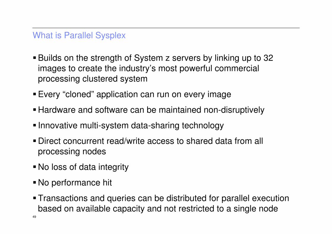
What is Parallel Sysplex
�Builds on the strength of System z servers by linking up to 32
images to create the industry’s most powerful commercial
processing clustered system
�Every “cloned” application can run on every image
�Hardware and software can be maintained non-disruptively
� Innovative multi-system data-sharing technology
�Direct concurrent read/write access to shared data from all
processing nodes
�No loss of data integrity
�No performance hit
�Transactions and queries can be distributed for parallel execution
based on available capacity and not restricted to a single node

50
Parallel Sysplex

51
Parallel Sysplex
– Loosely coupled multiprocessing
– Hardware/software combination
– Requires:
• Data sharing
• Locking
• Cross-system workload dispatching
• Synchronization of time for logging, etc.
• High-speed system coupling
– Hardware:
• Coupling Facility
Integrated Cluster Bus and ISC to
provide high-speed links to CF
• Sysplex Timer – Time Of Day clock synchronization
– Implemented in z/OS* and subsystems
• Workload Manager in z/OS
• Compatibility and exploitation in software subsystems, including
IMS*, VSAM*, RACF*, VTAM*, JES2*, etc.
- Rolling Maintenance System and Application Code
121
2
3
4
56
7
8
9
10
11
CouplingFacility
Shared data
Sysplex Timers
ESCON/FICON*
9672
zSeries
121
2
3
4
56
7
8
9
10
11
SystemZ9
Applications Applications

52
CONTINIOUSAVAILABILITY

53
Continuous availability
� Within a parallel sysplex cluster, it is possible to construct an environment with no single point of failure
� Peer instances can of a failing subsystem can take over recoveryresponsibility for resources held by the failing instance
� Alternatively the failing subsystem can be automatically restarted on still healthy systems
� In a parallel sysplex it is possible that the loss of a server may be transparent to the application and the server workload redistributed automatically with little performance degradation
� Each system is still individual
� Software upgrades can be rolled through one system at a time on a sensible timescale for the business

54
�Design goal of no application changes
�Benefits
–Scalability
–Integration of older applications with new workloads such as
web serving–With an existing sysplex there is very little infrastructure work
required for a new application. The existing infrastructure may
even be used without the need for a new server
Applications in a Parallel Sysplex

55
Policy Based Implementation

56
Although you can define more than one policy of each type (except for system logger) only one policy of each type can be active at a time. For system logger, there is only one LOGR policy in the sysplex.
Sysplex - Works with a Policy
� A policy is a set of rules and actions that systems in a sysplex are to follow when using certain zOS services.
� A policy allows zOS to manage systems specific resources in compliance with your system and resource requirements, but with little operator intervention.
� A policy can be set up to govern all systems in the sysplex or only selected.
NOTE: You might need to define more than one policy to allow for varying workloads, configurations, or other installation requirements at different times.
For example, you might need to define one policy for your prime shift operations and another policy for other times (end of month).
� The following policies can be used to enhance systems management in a sysplex:– The coupling facility resource management (CFRM) policy allows you to define how zOS is to
manage coupling facility resources.– The sysplex failure management (SFM) policy, allows you to define how MVS is to manage
system failures, signaling connectivity failures, and PR/SM reconfiguration actions.– The workload management (WLM) policy allows you to define service goals for workloads.– The automatic restart management policy allows you to define how MVS is to manage
automatic restarts of started tasks and batch jobs that are registered as elements of automatic restart management.
– The system logger policy, (LOGR), allows you to define, update, or delete structure or logstream definitions.

57
Sysplex Timers use a new server timer protocol (STP)
� The Server Time Protocol is a new server wide facility keeping all clocks synchronized
– There is no additional hardware required as in the previous type configuration.

58
Intelligent Resource Director (IRD)
Intelligent Resource Director, a feature of Mainframe hardware
and the Parallel Sysplex, is designed to further extend the lead
of the Mainframe environment in managing multiple
heterogeneous workloads with various business priorities
toward achieving their goals. Through its use, a more
synergistic relationship is established between z/OS and
Mainframe hardware with respect to the allocation of resources
among logical partitions.
WLM is responsible for enabling business-goal policies to be met
for the set of applications and workloads. IRD implements the
adjustments that WLM recommends to local sysplex images by
dynamically taking the hardware (CPU and channels) to the
LPAR where it is most needed. IRD has three main areas of
responsibility:
� LPAR CPU management
� Channel Subsystem priority queuing
� Dynamic channel path management

59
Intelligent Resource Director (IRD)
Intelligent Resource Director is not actually a product or a system component; rather it
is three separate but mutually supportive functions:
� WLM LPAR CPU Management
– This provides a means to modify an LPAR weight to a higher value in order to
move logical CPUs to that LPAR which is missing its service level goal.
� Dynamic Channel-path Management (DCM)
– Dynamic Channel-path Management is designed to dynamically adjust the channel
configuration in response to shifting workload patterns.
– DCM is implemented by exploiting functions in software components, such as
WLM, I/O, and Hardware Configuration. This supports DASD controller in order to
have the system automatically manage the number of I/O paths available to Disk
devices.
� Channel Subsystem I/O Priority Queueing (CSS IOPQ)
– This feature prioritizes I/O out through the channel and uses the SAP engine to create a
queue

60
System z LPAR Cluster A
Processor Resource / Systems Manager
System z LPAR Cluster B
Processor Resource / Systems Manager
z/VM z/OS
Linux
PRODUCTION AWASCICSDB2
z/OS z/OS
Production BWASCICSDB2
Intelligent Resource Director Intelligent Resource Director
TESTINGBatch
(low priority)
Weight Weight Weight Weight40 60 65 3565 35 90 10
PR/SM, IRD and WLM work together to ensure that the resources of the server are
correctly balanced to enable work to complete within stated policy goals
NeedsMore
Resources
NeedsMore
Resources
Prioritizing Work Across Images in a Server – IRD

61
Ring vs. Star Topology
When choosing a topology configuration, the following
considerations apply:
The GRS ring configuration is required when you have no coupling
facility available. Remember that GRS in a ring configuration can
use CTCA itself in order to pass the RSA, without the need for XCF.
The GRS star configuration is suggested for all Parallel Sysplexconfigurations. The GRS star configuration allows for sysplex
growth, and also is of value to installations currently running a
sysplex because of the improved responsiveness, the reduced
consumption of processor and storage, and the better availability
and recovery time.

62
GDPS
�A geographically dispersed parallel sysplex is the ultimate disaster
recovery and continuous availability solution for a multi-site
enterprise
�Two sites up to 100 fiber kilometers apart may be connected for
synchronous updates
�Asynchronous techniques may be used over this distance

63
Data Flow using Global Mirroring

64
Time
consistent
data
X
GDPS

65
Multiple Site Workload – Site 1 Failure

66
CICS –Sysplex (CICSplex)

67
DB2 Data Sharing with Group Buffer Pools