Introduction to KROHNE EMF...26 | Introduction to KROHNE EMF Dosing Separation system Volumetric...
114
Introduction to KROHNE EMF Product group presentation
Transcript of Introduction to KROHNE EMF...26 | Introduction to KROHNE EMF Dosing Separation system Volumetric...

Introduction to KROHNE EMF Product group presentation

Introduction to KROHNE EMF Agenda
1. Measurement principle
2. Product portfolio
3. OPTIFLUX
4. TIDALFLUX
5. WATERFLUX
6. Signal converter
7. Summary

Measurement principleIntroduction to electromagnetic flowmeters
EMF = ElectroMagnetic Flowmeter or often referred to as a magmeter or MID?
Used in virtually any industry and for a very wide range of applications
Popular solution for measuring liquid flows from
Liquids with/without solids contents
Drinking water
Slurries & sludges
Chemicals
Pulps & pastes
Constraint:
Liquids with a minimum electrical conductivity
So no oil, gas, steam, or demineralised water
3
OPTIFLUX 4300C
| Introduction to KROHNE EMF

Measurement principleElectromagnetic flow measurement 1/2
4
L
B
v
+-
L
| Introduction to KROHNE EMF

Measurement principleElectromagnetic flow measurement 2/2
5
L
B
v
L
U
B
U
U = B . L . v
ALL
v
Q = v . A
U ~vMedium
| Introduction to KROHNE EMF

Measurement principleElectromagnetic flowmeter
Signal converter
+
Sensor
=
Flowmeter
6 | Introduction to KROHNE EMF

Measurement principleStructure of the sensor
Measuring tube
Liner
Electrode pair
Field coil pair
Magnetic shield
Coil housing
Connection box
Grounding
− Grounding rings
− Reference electrode
− Virtual reference Typical materials
Non-ferromagnetic stainless steel with an electrically
insulating liner or internal coating, plastic or ceramic
7 | Introduction to KROHNE EMF

Measurement principleElectromagnetic flowmeter signal converter
Output
Status
Pulse
Frequency [Hz]
Current 4 – 20 [mA]
Noise filtering
Diagnosis
Current for
field coils
[mA]
Electrode
voltage
[mV]
Output
+ 7.184 ms
Sensor Process
Signal
converter
8 | Introduction to KROHNE EMF

Measurement principleEMF | Widespread use in most industries
9 | Introduction to KROHNE EMF
Source: Flow Research (2013)

Measurement principleInstallation guidelines
≥ 10 DN
≥ 3 DN≥ 5 DN
Control valve behind the measuring deviceFor clean water applications where a straight inlet of 5 DN or 3 DN
outlet is unavoidable, a special electromagnetic flowmeter without
straight inlet or outlet runs can be selected
10 | Introduction to KROHNE EMF

Measurement principleInstallation guidelines
Never install it in an upper pipe elbow or
descending pipeline
Do not install directly in front of a free outlet
11 | Introduction to KROHNE EMF

Measurement principleInstallation guidelines
Avoid vacuum, cavitation and gas bubbles
1
2
12 | Introduction to KROHNE EMF

Measurement principleInstallation guidelines
13 | Introduction to KROHNE EMF
Avoid external influences (such as magnetic sources and vibrations)

Measurement principleGrounding electromagnetic flowmeters
T3T2
Flow
T1
+
-
Ground
Electronics
Sensor
14 | Introduction to KROHNE EMF
T = Terminal
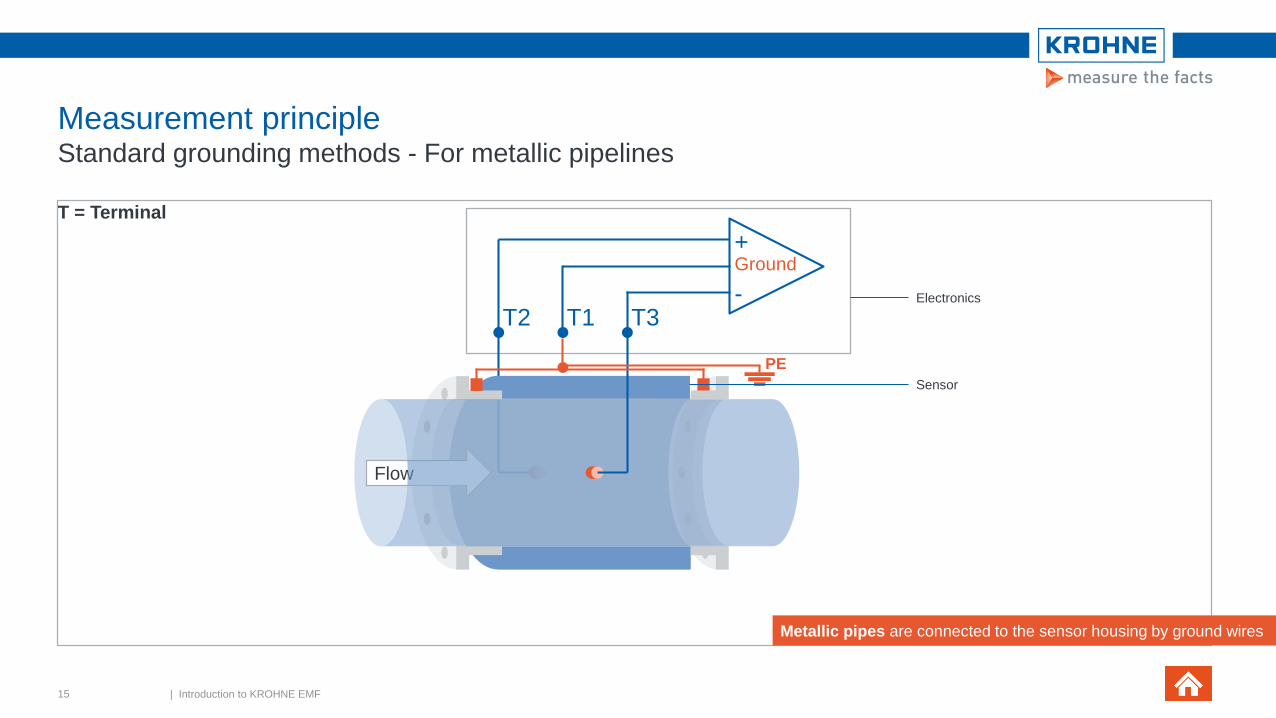
Measurement principleStandard grounding methods - For metallic pipelines
Flow
T3T2 T1
+
-
Ground
Electronics
Sensor
Metallic pipes are connected to the sensor housing by ground wires
PE
15 | Introduction to KROHNE EMF
T = Terminal
T3T2 T1
+
-
Ground
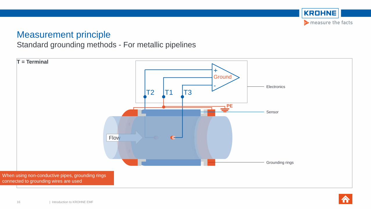
When using non-conductive pipes, grounding rings
connected to grounding wires are used
Electronics
Sensor
Grounding rings
Flow
PE
Measurement principleStandard grounding methods - For metallic pipelines
16 | Introduction to KROHNE EMF
T = Terminal

Measurement principleStandard grounding methods - With grounding electrode
T3T2 T1
+
-
Ground
Electronics
Sensor
Electrode
Flow
PE
This design requires a specially designed sensor.
With potential differences between the product
and earth, equalising currents may occur
and electrolytically damage the grounding
electrodes
One grounding electrode is directly connected to
the sensor housing.
17 | Introduction to KROHNE EMF
T = Terminal

Measurement principleReference electrode with conductive measuring tubes
T3T2 T1
+
-
Ground
Electronics
Sensor
PE Reference
electrode
Flow
However: noise affects the electrodes
The reference electrode forms the
common earth for the electronics (T1)
The reference electrode is NOT connected to the
flow sensor housing (unlike the grounding
electrode)
Handling
++
Price
+/-
Measuring
quality
+
18 | Introduction to KROHNE EMF
T = Terminal

Measurement principleElectronics with virtual reference
T3T2 T1
+
-
Ground
PE
Flow
Electronics
Sensor
Reference
electrode
The common earth is formed
by the measuring electrodes
(terminal 2 and terminal 3)
The sensor is identical to the
standard device.
No practical problems, even
when used ungrounded in systems
where voltages and currents are
applied to the pipelineHandling
++
Price
++
Measuring
quality
+
19 | Introduction to KROHNE EMF
T = Terminal

Measurement principleLimitations in the use of virtual reference
20 | Introduction to KROHNE EMF
Virtual reference Standard
Nominal sizes ≥ DN 10 mm
≥ 3/8 inch
≥ DN 2.5 mm
≥ 1/10 inch
Conductivity ≥ 200 µS/cm ≥ 1 µS/cm
Remote version:
Signal cable type
Only DS DS and BTS
Remote version:
Signal cable length
≤ 50 m
≤ 150 ft
≤ 600 m
≤ 1800 ft

Measurement principleCalibration
Piston prover
− DN 2.5 to DN 150
Calibration rig
− DN 200 to DN 3000
Calibration with water
− Changes to the properties caused by pressure are negligible
− Influences of temperature differences are known
Calibration at reference conditions
All calibration rigs with flow straighteners, for stable, fully developed flow profiles
21 | Introduction to KROHNE EMF

Measurement principleCalibration with a piston prover
A known volume of water is "pressed" through the measuring device,
performed by the computer
When successful:
− Calibration certificate is issued
Two deciding factors are at play when using piston provers
− The diameter of the cylinder
− The position of the piston displacing the water
The displaced volume is calculated using the inner diameter of the cylinder
and the measured movement
For sizes up to DN 300
Accuracy of the calibration rig: 10 times more accurate
than the measuring device to be calibrated Filling and degassing
Drainage
Ruler on piston rod
D
V
22 | Introduction to KROHNE EMF

Measurement principleCalibrating with a calibration tower
The uncertainty of these KROHNE calibration towers is
significantly less than the error limits of the measuring devices to
be tested
RvA accreditation by NMi
Traceability to international standards
Nominal size DN 3000 or 120 inches
Maximum flow rate: 30,000 m³/h
Uncertainty: 0.013%
23 | Introduction to KROHNE EMF

Introduction to KROHNE EMF Agenda
1. Measurement principle
2. Product portfolio
3. OPTIFLUX
4. TIDALFLUX
5. WATERFLUX
6. Signal converter
7. Summary

Product portfolioOPTIFLUX│KROHNE electromagnetic flowmeters
OPTIFLUX 1000 Light weight & compact for space saving installation. The economic solution
OPTIFLUX 2000The reliable solution for all W&WW applications
OPTIFLUX 4000 The all-round solution for process industries
OPTIFLUX 5000 Sandwich / FlangedMaximum media resistance,abrasion resistance & accuracy with high-performance ceramics
OPTIFLUX 6000 The food & pharmaceutical specialist
WATERFLUX 3000For easy installation in restricted spaces in drinking water applications
25 | Introduction to KROHNE EMF

OPTIFLUXTypical applications
26 | Introduction to KROHNE EMF
Dosing Separation system Volumetric filling O&G Water injection Mining - Copper
Batching – tanks Heavy paper stock Water filter plantMagnesium oxide O&G Seawater
Mixing Bentonite dosingWater distribution Dosing mayonnaise Aluminium refinery

Product portfolioWide range of liner solutions for every application
27 | Introduction to KROHNE EMF
Wide diameter range
Variable thickness
Wide temperature & pressure range
High chemical & abrasion resistance
Dimensional stability
Surface / hygienic properties (SIP/CIP)
Approvals (Drinking water, Hygienic)

Product portfolioWide range of liner solutions for every application
28 | Introduction to KROHNE EMF
Wide diameter range
Variable thickness
Wide temperature & pressure range
High chemical & abrasion resistance
Dimensional stability
Surface / hygienic properties (SIP/CIP)
Approvals (Drinking water, Hygienic)

Product portfolioMaterials
OPTIFLUX
1000
OPTIFLUX
2000
WATERFLUX
3000
OPTIFLUX
4000
OPTIFLUX
5000
OPTIFLUX
6000
Liner material
PFA ⚫ - - ⚫ - ⚫
Hard rubber - ⚫ - ⚫ - -
PP - ⚫ - - - -
PO - ⚫ - - - -
PTFE - - - ⚫ - -
ETFE - - - ⚫ - -
PU - - - ⚫ - -
Ceramic - - - - ⚫ -
Rilsan - - ⚫ - - -
Soft rubber - - - - -
⚫ Standard Available option
29 | Introduction to KROHNE EMF

Product portfolioMaterials
OPTIFLUX
1000
OPTIFLUX
2000
WATERFLUX
3000
OPTIFLUX
4000
OPTIFLUX
5000
OPTIFLUX
6000
Electrode material
Hastelloy ⚫ - ⚫ ⚫ - ⚫
SS - ⚫ -
Pl, Ta, Ti - - - -
Cermet - - - - ⚫ -
⚫ Standard Available option
30 | Introduction to KROHNE EMF

Product portfolioOperating conditions
DesignOPTIFLUX
1000
OPTIFLUX
2000
WATERFLUX
3000
OPTIFLUX
4000
OPTIFLUX
5000
OPTIFLUX
6000
Temperature
Process -25 …+120 0C -25 …+90 0C -5 …+70 0C -40 …+180 0C -40 …+180 0C -40 …+180 0C
-13 …+248 0F -13 …+194 0F +23 …+1580F -76 …+356 0F -76 …+356 0F -76 …+356 0F
Ambient -25 …+65 0C -40 …+65 0C -40 …+65 0C -40 …+65 0C -40 …+65 0C -40 …+65 0C
-13 …+149 0F -40 …+149 0F -40 …+149 0F -40 …+149 0F -40 …+149 0F -40 …+149 0F
Protection category
IP rating IP66/67 IP66/67/ 68 IP66/67/68 IP66/67/68 IP66/67/68 IP66/67/68
NEMA 4/4X 4/4X/6/6P 4/4X/6/6P 4/4X/6/6P 4/4X/6/6P 4/4X/6/6P
31 | Introduction to KROHNE EMF

Product portfolioApprovals
OPTIFLUX
1000
OPTIFLUX
2000
WATERFLUX
3000
OPTIFLUX
4000
OPTIFLUX
5000
OPTIFLUX
6000
Ex
-
EEx
IEC Ex
CSA
FM
Nepsi
-
EEx
CSA
FM
EEx
CSA
FM
EEx
CSA
FM
Custody
transfer
MI-001
OIML R49
MI-005
OIML R117
MI-001
OIML R49
MI-005
OIML R117
MI-001
MI-004
MI-001
OIML R49
MI-005
OIML R117
MI-004
MI-005 MI-005
Drinking
water
-
ACS
DVGW-W270
KTW
NSF
WRAS
ACS,
DVGW-W270
NSF
TZW /UBA
WRAS
KIWA
- -
Hygienic FDA - - - FDA FDA, 3A,
EHEDG
32 | Introduction to KROHNE EMF

Product portfolioModular signal converter line
Compact field
Compact wall Compact wall
Compact field/ wall
rack
1. IFC 050
The basic & robust solution
2. IFC 100
The standard and economical solution
3. IFC 300
The all-round signal converter solution
4. IFC 070
33| Introduction to KROHNE EMF

Product portfolioHousing variants
Signal converter Compact (C) Field (F) Wall (W) Rack (R)
IFC 050
IFC 100
IFC 300
IFC 070
34 | Introduction to KROHNE EMF
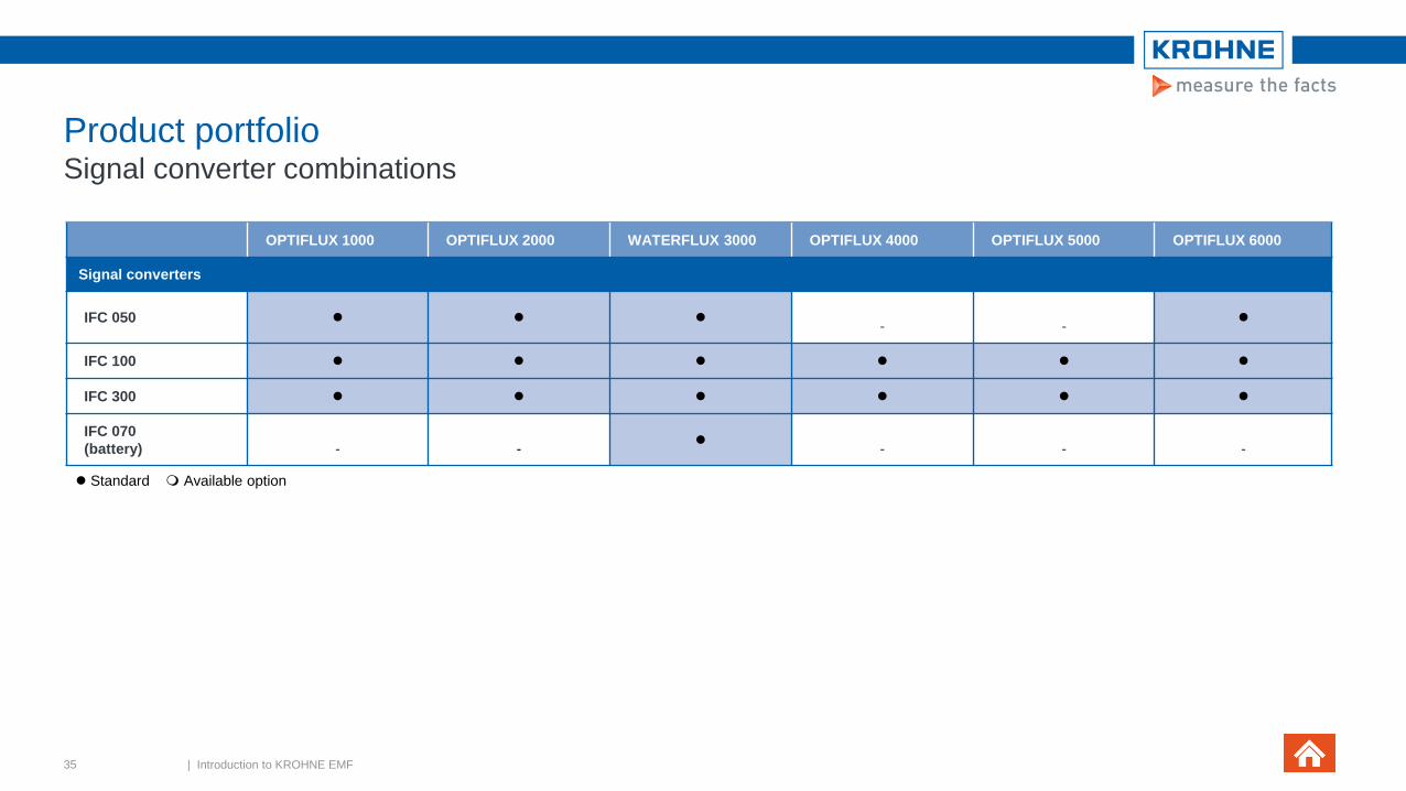
Product portfolioSignal converter combinations
⚫ Standard Available option
OPTIFLUX 1000 OPTIFLUX 2000 WATERFLUX 3000 OPTIFLUX 4000 OPTIFLUX 5000 OPTIFLUX 6000
Signal converters
IFC 050 ⚫ ⚫ ⚫- -
⚫
IFC 100 ⚫ ⚫ ⚫ ⚫ ⚫ ⚫
IFC 300 ⚫ ⚫ ⚫ ⚫ ⚫ ⚫
IFC 070
(battery) - -⚫
- - -
35 | Introduction to KROHNE EMF

Product portfolioSpecial purpose meters
1. WATERFLUX 3070
The battery-powered solution
For remote locations without mains power
2. TIDALFLUX 2300 F
For partially filled pipes
3. OPTIFLUX 4040
The 2-wire solution
that performs like a 4-wire device
4. OPTIFLUX 7300
Non-wetted capacitive electrodes
and a ceramic liner.
Available in flange and sandwich design
5. BATCHFLUX 5500 F
For volumetric filling systems in the beverage industry
36 | Introduction to KROHNE EMF

Introduction to KROHNE EMF Agenda
1. Measurement principle
2. Product portfolio
3. OPTIFLUX
4. TIDALFLUX
5. WATERFLUX
6. Signal converter
7. Summary

OPTIFLUXModular signal converters
OPTIFLUX 2000
OPTIFLUX 2300COPTIFLUX 2100COPTIFLUX 2050C
38 | Introduction to KROHNE EMF

OPTIFLUX KROHNE electromagnetic flow sensors
Largest diameter range
DN2.5 to DN3000
Wide range of sensor connections
Flange connections
− Nominal sizes & pressure ratings acc. to EN, ASME, ISO, JIS, AWWA
Sandwich connections
Hygienic connections
Special sensor constructions (on request)
Pressure ratings of up to 2500
Wide choice of sensor materials
SS, Duplex, 6mo
External coatings for offshore or subsoil installation
39 | Introduction to KROHNE EMF

OPTIFLUXKROHNE electromagnetic flow sensors
Large choice of liners
A solution for every application with
PFA, polypropylene, EFTE, hard rubber, soft rubber,
polyurethane, Rilsan, ceramics
Flexible sizes: large diameter range, special IDs &
thicknesses, special constructions
Unique ceramics with fused-in electrodes
Rilsan coating for drinking water
Patented mesh for PFA liner
Range of electrode options
Corrosion resistant & leak tight
Special designs: materials, retractable or pointed
40 | Introduction to KROHNE EMF

OPTIFLUX High-performance ceramics
Ceramic oxide liner zirconium
(developed in close cooperation with FRIATEC AG)
Hard as diamond, dimensionally stable
Benefits:
− Form stability of the tube even with quick temperature changes and pressure
stresses
− Highly resistant to caustic, corrosive & abrasive media
Conical flow tube design
Optimises the flow profile, increases the flow velocity in the tube
Benefits:
− Large turndown ratio, highly accurate measurements, reduces risk of
deposits
Leading metrological institutes use OPTIFLUX 5000 as their master meter
41 | Introduction to KROHNE EMF

OPTIFLUX Target industries
Key target markets
Water & Wastewater
Food & Beverage
Chemicals
Paper & Pulp
Metals and Mining
Oil & Gas / Refining
Power / Energy
District Energy
Pharmaceuticals
Other
42 | Introduction to KROHNE EMF
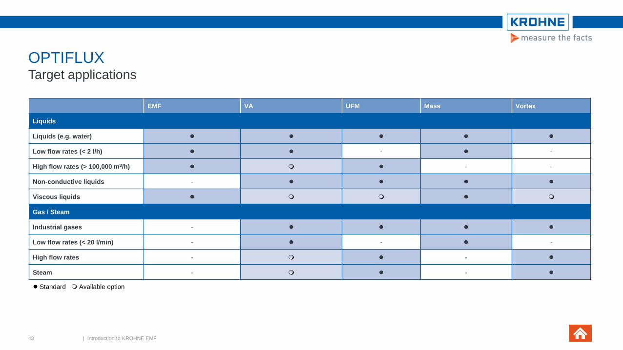
OPTIFLUXTarget applications
EMF VA UFM Mass Vortex
Liquids
Liquids (e.g. water) ⚫ ⚫ ⚫ ⚫ ⚫
Low flow rates (< 2 l/h) ⚫ ⚫ - ⚫ -
High flow rates (> 100,000 m3/h) ⚫ ⚫ - -
Non-conductive liquids - ⚫ ⚫ ⚫ ⚫
Viscous liquids ⚫ ⚫
Gas / Steam
Industrial gases - ⚫ ⚫ ⚫ ⚫
Low flow rates (< 20 l/min) - ⚫ - ⚫ -
High flow rates - ⚫ - ⚫
Steam - ⚫ - ⚫
⚫ Standard Available option
43 | Introduction to KROHNE EMF

OPTIFLUXTarget applications
EMF VA UFM Mass Vortex
Special applications
Slurries, media with solids ⚫ - - -
Emulsions (oil / water) ⚫ ⚫
Corrosive liquids ⚫ ⚫ ⚫ ⚫
Corrosive gases - -
Bi-directional measurement ⚫ - ⚫ ⚫ -
44 | Introduction to KROHNE EMF
⚫ Standard Available option

OPTIFLUXTypical applications
45 | Introduction to KROHNE EMF
Dosing Separation system Volumetric filling O&G Water injection Mining - Copper
Batching – tanks Heavy paper stock Water filter plantMagnesium oxide O&G Seawater
Mixing Bentonite dosingWater distribution Dosing mayonnaise Aluminium refinery

OPTIFLUXTarget applications
Industry Application OPTIFLUX
1000
OPTIFLUX
2000
OPTIFLUX
4000
OPTIFLUX
5000
OPTIFLUX
6000
OPTIFLUX
4040 C
OPTIFLUX
7300 C
TIDAFLUX
2300 F
WATERFLUX
3000
BATCHFLU
X 5500 C
Water & Wastewater
Distribution network ⚫ ⚫ - - - ⚫ - - ⚫ -
(Waste) water treatment ⚫ ⚫ ⚫ ⚫ - ⚫ - - ⚫ -
Sludge / Sewage - ⚫ ⚫ ⚫ ⚫ - - -
Partially filled pipelines - - - - - - - ⚫ - -
Revenue metering ⚫ ⚫ ⚫ ⚫ - ⚫ - - ⚫ -
Irrigation - ⚫ ⚫ ⚫ - ⚫ ⚫ - ⚫ -
Abstraction - - - - - - - - ⚫ -
⚫ Standard Available option
46 | Introduction to KROHNE EMF

OPTIFLUXTarget applications
Industry Application OPTIFLUX
1000
OPTIFLUX
2000
OPTIFLUX
4000
OPTIFLUX
5000
OPTIFLUX
6000
OPTIFLUX
4040 C
OPTIFLUX
7300 C
TIDAFLUX
2300 F
WATERFLUX
3000
BATCHFLUX
5500 C
Chemical
Dosing of additives - ⚫ ⚫ - - ⚫ - - ⚫
Corrosive /abrasive liquids
/slurries - ⚫ ⚫ - - ⚫ - - ⚫
Hazardous areas - ⚫ ⚫ - - ⚫ - - -
⚫ Standard Available option
47 | Introduction to KROHNE EMF

OPTIFLUXTarget applications
Industry Application OPTIFLUX
1000
OPTIFLUX
2000
OPTIFLUX
4000
OPTIFLUX
5000
OPTIFLUX
6000
OPTIFLUX
4040 C
OPTIFLUX
7300 C
TIDAFLUX
4300 F
WATERFLUX
3000
BATCHFLUX
5500 C
Paper & Pulp
Pulp - ⚫ ⚫ - - - - - - -
Liquor - - ⚫ ⚫ - - - - -
Additives,
bleaches,
colourants
- - ⚫ ⚫ - - - - ⚫
Food & Beverage
Food & beverage - - - ⚫ ⚫ - ⚫ -- - ⚫
Blending, dosing,
batching - - - ⚫ ⚫ ⚫ - - ⚫
Volumetric filling
machines- - - - - - - - - ⚫
⚫ Standard Available option
48 | Introduction to KROHNE EMF

OPTIFLUXTarget applications
Industry Application OPTIFLUX
1000
OPTIFLUX
2000
OPTIFLUX
4000
OPTIFLUX
5000
OPTIFLUX
6000
OPTIFLUX
4040 C
OPTIFLUX
7300 C
TIDAFLUX
4300 F
WATERFLUX
3000
BATCHFLUX
5500 C
Other
HVAC ⚫ ⚫ - - - - - -
Machinery ⚫ - - ⚫ - - ⚫ - - ⚫
Dredging, materials
&
mining, ore
- - ⚫ ⚫ - - - - - -
Master / transfer
meters
- - - ⚫ - - - - - -
⚫ Standard Available option
49 | Introduction to KROHNE EMF
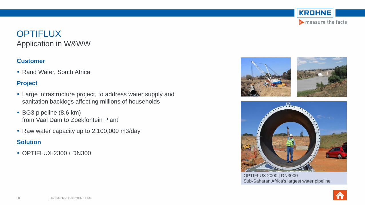
OPTIFLUXApplication in W&WW
Customer
Rand Water, South Africa
Project
Large infrastructure project, to address water supply and
sanitation backlogs affecting millions of households
BG3 pipeline (8.6 km)
from Vaal Dam to Zoekfontein Plant
Raw water capacity up to 2,100,000 m3/day
Solution
OPTIFLUX 2300 / DN300
50 | Introduction to KROHNE EMF
OPTIFLUX 2000 | DN3000
Sub-Saharan Africa's largest water pipeline

OPTIFLUXApplication in O&G
Customer & scope:
Petroleum Development of Oman (PDO)
Several hundred OPTIFLUX 4300
Diameters between 1” and 20”
Pressure ratings up to 1500 lbs (approx. 250 bar)
Why OPTIFLUX 4300?
Robust construction
Diagnostic capabilities
Good price / performance ratio
Support given including training
> Not a single complaint over the last five years!
51 | Introduction to KROHNE EMF

OPTIFLUX Application in mining
Customer
Large copper/gold facility in South East Asia
Application
Value of total gold production throughput approx. USD 3
million p/d
Four hydrocyclone feed lines for classification of particles
in slurries
Coarse & fine materials cause major abrasive wear
Result: frequent replacement of flow meters (up to every
6 months)
52 | Introduction to KROHNE EMF
OPTIFLUX 4300 at large copper/gold mine
Introduction to KROHNE EMF Agenda
1. Measurement principle
2. Product portfolio
3. OPTIFLUX
4. TIDALFLUX
5. WATERFLUX
6. Signal converter
7. Summary

TIDALFLUX Unique solution for partially filled pipes
54 | Introduction to KROHNE EMF
For partially filled pipes in the W&WW industry
Diameter range up to DN1600 / 64"
Patented, non-contact level measurement
Measurement possible between 10% and 100% filling
Sensor & converter available in Ex zone 1
High abrasion resistance and chemical resistance
Electrodes below 10% filling level, therefore no blind
folding by fat & oil floating on water surface
Complete factory calibration - no on-site calibration
necessary
Target applications:
wastewater, sludge, influent, effluent
TIDALFLUX 2300 F
For partially filled pipes

Introduction to KROHNE EMF Agenda
1. Measurement principle
2. Product portfolio
3. OPTIFLUX
4. TIDALFLUX
5. WATERFLUX
6. Signal converter
7. Summary

WATERFLUXKROHNE electromagnetic flow sensors
1. Diameter range: DN25 – 600
2. Unique flow sensor design with rectangular cross section
3. Rilsan coating well accepted & approved for drinking water
4. NEW: Integrated P&T sensor
5. Built-in reference electrode
makes grounding rings obsolete
56 | Introduction to KROHNE EMF
4
5

WATERFLUXKROHNE electromagnetic flow sensors
WATERFLUX 3070 V3
Key features:
Pulse output or Modbus communication
Quick & simple installation
IP68 F converter for installation in measuring pits
Battery or mains power with battery back-up
Small footprint for installation
in cabinets or measurement chambers
Pressure & temperature data
Measurement sensitivity at low flow rates
Robust sensor
Threaded connections
57 | Introduction to KROHNE EMF

WATERFLUXRectangular cross section
Flow profile independency
− Stronger magnetic field (B)
− Homogeneous magnetic field strength (B)
Flow profile disturbances squeezed out by contraction
Mean flow velocity (v) is doubled
Low uncertainty
Good low flow performance
Large turndown ratio R
Substantial reduction of straight lengths: 0D inlet, 0D
outlet
Longest battery service life of up to 15 years
58 | Introduction to KROHNE EMF
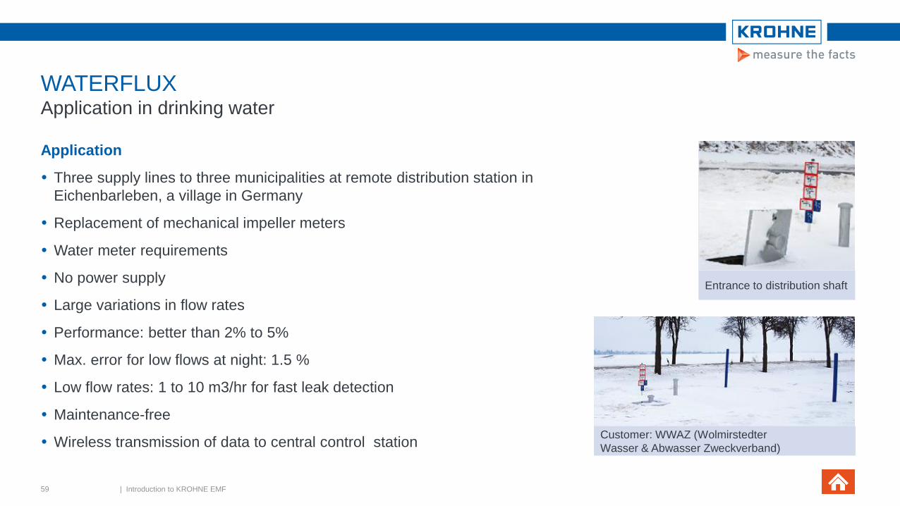
WATERFLUXApplication in drinking water
Application
Three supply lines to three municipalities at remote distribution station in
Eichenbarleben, a village in Germany
Replacement of mechanical impeller meters
Water meter requirements
No power supply
Large variations in flow rates
Performance: better than 2% to 5%
Max. error for low flows at night: 1.5 %
Low flow rates: 1 to 10 m3/hr for fast leak detection
Maintenance-free
Wireless transmission of data to central control station
59 | Introduction to KROHNE EMF
Entrance to distribution shaft
Customer: WWAZ (Wolmirstedter
Wasser & Abwasser Zweckverband)

WATERFLUX Application in drinking water (1/2)
Solution: WATERFLUX 3070
2 x DN 150, 1 x DN 200
Battery power
Large CT turndown ratio (1:400)
Measuring error: < 0.5% of MV
(also at flow rates of <10 m3/h)
0D inlet, 0D outlet
Bi-directional
Reference electrode –
No separate grounding
IP 68 (sensor)
60 | Introduction to KROHNE EMF

WATERFLUX Application in drinking water (2/2)
61 | Introduction to KROHNE EMF
Setting Measuring freqzency Number of measurements per
unit of time
Battery life
approx. with 2
batteries
Battery life
approx. With
an external
battery pack
Standard 1/15Hz 1 every 15 seconds 15 years 20 years
modified 1Hz 1 every second 1,5-2,5 years 3-5 years

Introduction to KROHNE EMF Agenda
1.Measurement principle
2.Product portfolio
3.OPTIFLUX
4.TIDALFLUX
5.WATERFLUX
6.Signal converter
1.General
2.Variants and sensor combinations
3.Diagnostics
4.Technical data
7.Summary
Introduction to KROHNE EMF Agenda

Signal convertersGeneral
IFC 300
Functions
To generate a coil current for the sensor
To amplify the measured voltage
To convert it into a digital value
To filter noise and interference signals
To diagnose device and process
Available data
Flow velocity, volume flow, mass flow
Conductivity, coil temperature
Alarms, warnings
63 | Introduction to KROHNE EMF
New: PROFINET I/O interface available for IFC 300

Signal convertersGeneral
IFC for electromagnetic flowmeters
UFC for ultrasonic flowmeters
MFC for Coriolis mass flowmeters
General Device Concept
Uniform
User interface
Electronics
suitable for various housings
Extensive device & process diagnostic functions
Communication interfaces
64 | Introduction to KROHNE EMF

Signal convertersGeneral
Price
Performance
IFC 100
The standard
solution
IFC 300
The all-round solution
IFC 050
The basic & robust solution
IFC 070
The battery powered,
stand-alone solution
65 | Introduction to KROHNE EMF

Signal convertersGeneral
Blind / with display 00 / 100 / 450
Housing & display variants
66 | Introduction to KROHNE EMF

Introduction to KROHNE EMF Agenda
1.Measurement principle
2.Product portfolio
3.OPTIFLUX
4.TIDALFLUX
5.WATERFLUX
6.Signal converter
1.General
2.Variants and sensor combinations
3.Diagnostics
4.Technical data
7.Summary
Introduction to KROHNE EMF Agenda

Signal convertersVariants and sensor combinations
Ex version Stainless steel version Rack versionIP68 version
68 | Introduction to KROHNE EMF

Signal convertersVariants and sensor combinations
IFC 050 IFC 100 IFC 300 IFC 070
Housing variants
Compact (C ) ⚫ ⚫ ⚫ ⚫
Field ( F ) - - ⚫ ⚫
Wall ( W ) ⚫ ⚫ ⚫ -
Rack ( R ) - - ⚫ -
Ex - -
Stainless-steel - - -
IP68 - - -
⚫ Standard Available option
69 | Introduction to KROHNE EMF

Signal convertersVariants and sensor combinations
IFC 050 IFC 100 IFC 300 IFC 070
Display
With ⚫ ⚫ ⚫ ⚫
Without / blind - - -
Compact 00 - ⚫ - -
Compact 100 ⚫ - - -
Compact 450 - -
⚫ Standard Available option
70 | Introduction to KROHNE EMF

Signal convertersVariants and sensor combinations
IFC 300
OPTIFLUX 2300COPTIFLUX 1300 C OPTIFLUX 4300C OPTIFLUX 5300C OPTIFLUX 6300C OPTIFLUX 7300C WATERFLUX 3300C
71 | Introduction to KROHNE EMF

Signal convertersVariants and sensor combinations
IFC 050 IFC 100 IFC 300 IFC 070
Sensor combinations
OPTIFLUX 1000 ⚫ ⚫ ⚫ -
OPTIFLUX 2000 ⚫ ⚫ ⚫ -
OPTIFLUX 4000 ⚫ ⚫ ⚫ -
OPTIFLUX 5000 - ⚫ ⚫ -
OPTIFLUX 6000 ⚫ ⚫ ⚫ -
OPTIFLUX 7000 - - ⚫ -
WATERFLUX 3000 ⚫ ⚫ ⚫ ⚫
Diameter range
Smallest DN10
3/8”
DN2.5
1/10”
DN2.5
1/10”
DN25
1”
Largest DN1200
48”
DN1200
48”
DN3000
120”
DN600
24”
⚫ Standard Available option
72 | Introduction to KROHNE EMF

Electromagnetic flowmetersAgenda
1.Measurement principle
2.Product portfolio
3.OPTIFLUX
4.TIDALFLUX
5.WATERFLUX
6.Signal converter
1.General
2.Variants and sensor combinations
3.Diagnostics
4.Technical data
7.Summary
Introduction to KROHNE EMF Agenda

Signal convertersDiagnostics
74 | Introduction to KROHNE EMF
✓ Electrodes:
Check on deposits or corrosion
✓ Accuracy test ✓ Check on flow profile disturbances
& partially filled pipes

WATERFLUX 3000Technical data
75 | Introduction to KROHNE EMF
⚫ Standard Available option
Diagnosis IFC 050 IFC 100 IFC 300
Pro
cess
Conductivity changes ⚫ ⚫ ⚫
Medium temperature
(threshold values) - ⚫ ⚫
Gas bubbles / solids - ⚫ ⚫
Empty pipe ⚫ ⚫ ⚫
Partial filling of sensor - - ⚫
Flow profile disrupted - - ⚫
External magnetic fields - - ⚫
Sen
so
r
Electrode
• Deposit/coating
• Short circuit corrosion
⚫ ⚫ ⚫
Liner deformation - - ⚫
FT Accuracy test - - ⚫
Linearity deviations - - ⚫
Diagnostic info
available via:
Local display
Status outputs
Fieldbuses
Pactware

Signal convertersOnline diagnostics
Possible causes of malfunctioning
Change to process conditions
Cavitations
Over-temperature & vacuum
Incorrect installation
Inappropriate electrode / liner material
Abrasion through solids
Electrode scaling/fouling
External magnetic fields
Defective instrument components
76 | Introduction to KROHNE EMF
OPTIFLUX 2300

Signal convertersContinuous (self-) testing
Flow sensor
Electrode fouling or scaling
Electrode corrosion
Electrode leakage
Liner deformation
Coil performance
Flow converter
Linearity check
I/O check
Functioning of converter components
Local process
Gas bubbles & solids
Installation
Liquid conductivity
Flowmeter temperature
Partially filled pipe
(Self-) tests exceed wish list defined by end users for
NAMUR guideline 2650
77 | Introduction to KROHNE EMF

Signal convertersOnline diagnostics
mA output, monitored for:
• Interruption
• Permissible load
Signal processing,
electronics monitored for:
• Accuracy
• Linearity
• µP function
• Memory function
• Temperature
Process, monitored for:
• Minimum conductivity
• Conductivity limits
• Flow profile
• Temperature
• Entrained gas
• Electrode corrosion
Field current, monitored for:
• True value
Field coils, monitored for:
• Resistance
• Wire break / short-circuit
• temperature
Magnetic field, induction B,
signal voltage U, monitored
for:
• Effect of external magnetic
fields
• Linearity of magnetic circuit
Measuring electrodes,
monitored for:
• Wire break / short-circuit
• Electrode fouling
• Electrode resistance
78 | Introduction to KROHNE EMF
OPTIFLUX 2300

Signal convertersOnline diagnostics
Issue
Scaling or fouling of electrode(s)
Test performed
Resistance measurement
Result
Warning when resistance is exceeding default preset
values
79 | Introduction to KROHNE EMF
Re
Rl
Re
Resistance liquid
Resistance
electrode

Signal convertersOnline diagnostics
Resistance of electrodes (Re) dependent on electrical
conductivity (s) of the liquid and electrode area
Electrode diameter is programmed during calibration
Conductivity of liquid is an interesting process and
diagnosis variable
80 | Introduction to KROHNE EMF
d2
1Re
=
Re
Rl
Re
Resistance liquid
Resistance
electrode

Signal convertersOnline diagnostics
ē
ē
ē
ē
ē ē
Issue
Electrode corrosion
Test performed
Electrode noise test
Result
Immediate warning when noise value increases above
default preset value
81 | Introduction to KROHNE EMF

Signal convertersOnline diagnostics
Normal flow measurement
Multiplication of electrode voltage with block wave in
phase with field coil excitation
Switching phases are suppressed
Result is volumetric flow
Noise calculation
Multiplication with 90° shifted block wave
Switching phases are suppressed
No noise means that the voltage is zero
82 | Introduction to KROHNE EMF
Electrode signal
Multiplication
1
-1
Result
Electrode signal
Multiplication
1
-1
Result

Signal convertersOnline diagnostics
Ele
ctro
de E
lectr
ode
Coil
Coil
Swelling
Abrasion
Diffusion
Chemical thermal
attack
Vacuum
Issue
Liner deformation
Mostly caused by installation
Or by vacuum at excessive temperature
Test performed
Flow profile check
Result
Warning generated at non-balanced electrode voltage
83 | Introduction to KROHNE EMF

Signal convertersOnline diagnostics
Ele
ctro
de
Coil part
Coil part
Ele
ctr
ode
Coil part
Coil part
Ele
ctro
de E
lectr
ode
Normal operation
Magnetic field from coil to coil
Voltage between electrodes is proportional to flow
Test phase
If no liner deformation, voltage between electrodes is zero
84 | Introduction to KROHNE EMF

Signal convertersOnline diagnostics
Flow
Ou
tpu
t
Issue
Linearity
Test performed
Functional test of sensor electronics through short
periodic change of field current
Result
Warning when linearity falls outside accuracy limits
85 | Introduction to KROHNE EMF

Signal convertersOnline diagnostics
I Field
U Electr
Q
Qindicated Uelectr / IField
ΔQ
1 2 3
Field current reduced to 50% during each measurement
cycle
Electrode signal should reflect this reduction
Flow signal does not change under normal conditions
86 | Introduction to KROHNE EMF

Signal convertersOnline diagnostics
Ele
ctro
de E
lectr
ode
Coil
Coil
Issues
Valves half open
Bends
Incorrect installation
External magnetic fields
Test performed
Flow profile check
Result
Warning generated
87 | Introduction to KROHNE EMF

Signal ConvertersOnline diagnostics
Issue
Pipe not completely filled
Test performed
Flow profile check
Result
Warning is generated when filling height drops below 75%
of the top flow tube level
V
88 | Introduction to KROHNE EMF

Signal convertersDiagnostics functions
OPTICHECK
On-site verification tool
Handheld portable device
To perform a series of performance
tests - on site – in less than 10 min.
Without the need of a wet calibration
/ removing the sensor out of the line
Hard copy verification report
Internal database for digital storage
of verification data
Option to download original factory
calibration settings from KROHNE
database
89 | Introduction to KROHNE EMF

Introduction to KROHNE EMF Agenda
1.Measurement principle
2.Product portfolio
3.OPTIFLUX
4.TIDALFLUX
5.WATERFLUX
6.Signal converter
1.General
2.Variants and sensor combinations
3.Diagnostics
4.Technical data
7.Summary
Introduction to KROHNE EMF Agenda

Signal convertersTechnical data
Outputs / Inputs
Status output (and/or )
Frequency output (Hz)
Pulse output
Current 4 – 20 (mA), incl. HART
Limit switch (and/or control input or current input)
Communication protocol
HART
Foundation Fieldbus
Profibus (PA|DP)
PROFINET
RS485 Modbus
91 | Introduction to KROHNE EMF
IFC 300 F

Signal convertersTechnical data
Display
Local display of flow velocity and volume
Text and graphic information
Large, high contrast display with a white backlight
Keys
Four optical buttons
No need to open the cover
to protect the display from dirt and dust
QuickStart menu
For easy commissioning and can be configured by the
user
IFC 300 F
92 | Introduction to KROHNE EMF

Intelligent user interface
4 x pushbuttons
when housing is open
4 x magnetic keys
when housing is closed
Signal convertersTechnical data
93 | Introduction to KROHNE EMF
IFC 050 IFC 050

Signal convertersTechnical data
94 | Introduction to KROHNE EMF

Signal convertersTechnical data
95 | Introduction to KROHNE EMF
⚫ Standard Available option
IFC 050 IFC 100 IFC 300 IFC 070
Outputs
Current (incl. HART) ⚫ ⚫ ⚫ -
Current active ⚫ - ⚫ -
Pulse ⚫ ⚫ ⚫ ⚫
Pulse active ⚫ - ⚫ -
Status / Limit switch ⚫ ⚫ ⚫ ⚫
Inputs
Control input / Binary - ⚫ -

Signal convertersTechnical data
96 | Introduction to KROHNE EMF
⚫ Standard Available option
IFC 050 IFC 100 IFC 300 IFC 070
Communication
HART ©⚫ ⚫ ⚫ -
Modbus -
Profibus PA /DP - - -
PROFINET - - -
Fieldbus - - -

Signal convertersTechnical data
IFC 050 IFC 100 IFC 300 IFC 070
EX Approvals
ATEX - -
IEC Ex - -
FM - -
CSA - -
NEPSI - -
Ex housing version
⚫ Standard Available option
97 | Introduction to KROHNE EMF

WATERFLUX 3000Technical data
98 | Introduction to KROHNE EMF
⚫ Standard Available option
IFC 050 IFC 100 IFC 300 IFC 070
Operating conditions
Electrical conductivity ≥ 20 μS/cm
Installation conditions
Virtual reference - - -
Protection category
Compact (C) IP66/67 IP66/67 IP66/67 IP68
Field (F) - - IP66/67 IP68
Wall (W) IP66/67 IP66/67 IP65 -
19” rack (R) - - IP20 -

Signal convertersTechnical data
IFC 050 IFC 100 IFC 300
Display & user interface
Counters (totalisers) 2 internal 2 internal 2 (/ 3) internal
Digits Max. 10 Max. 8 Max. 8
Buttons / keys 4 pushbuttons &
4 magnetic keys4 pushbuttons
4 optical keys &
infrared interface
Standard languages
EN, FR, DE, NL, PT, SE, ES, IT⚫ ⚫ ⚫
Quick Setup menu ⚫ ⚫ ⚫
Remote control
• PACTware®
• HART®
• AMS®
• PDM®
Generic DD’s & DTM’s
-
⚫
-
-
⚫
⚫
⚫
⚫
⚫
⚫
⚫
⚫
⚫ Standard Available option
99 | Introduction to KROHNE EMF
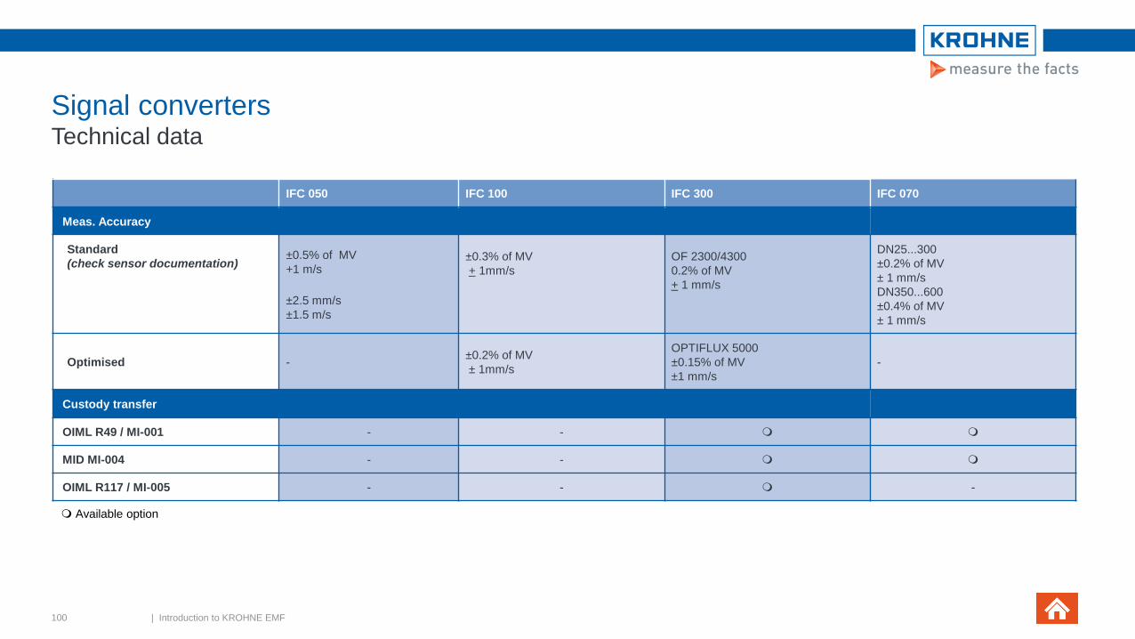
Signal convertersTechnical data
IFC 050 IFC 100 IFC 300 IFC 070
Meas. Accuracy
Standard
(check sensor documentation) ±0.5% of MV
+1 m/s
±2.5 mm/s
±1.5 m/s
±0.3% of MV
+ 1mm/s
OF 2300/4300
0.2% of MV
+ 1 mm/s
DN25...300
±0.2% of MV
± 1 mm/s
DN350...600
±0.4% of MV
± 1 mm/s
Optimised -±0.2% of MV
± 1mm/s
OPTIFLUX 5000
±0.15% of MV
±1 mm/s
-
Custody transfer
OIML R49 / MI-001 - -
MID MI-004 - -
OIML R117 / MI-005 - - -
Available option
100 | Introduction to KROHNE EMF

Signal convertersTechnical data
101 | Introduction to KROHNE EMF
Mains power Battery-powered Mains power with battery backup

Signal convertersTechnical data
IFC 050 IFC 100 IFC 300 IFC 070
Mains power
100 … 230 VAC ⚫ ⚫ ⚫ -
12 ... 24 VDC - ⚫ ⚫ -
24 VDC ⚫ - - -
24 VAC/DC - ⚫ ⚫ -
Mains power with battery back-up
FlexPower unit
100…230 VAC
10..30 V DC
- - - ⚫
Battery power
Internal (2) - - - ⚫
External (4) - - -
⚫ Standard Available option
102 | Introduction to KROHNE EMF

Introduction to KROHNE EMF Agenda
1. Measurement principle
2. Product portfolio
3. OPTIFLUX
4. TIDALFLUX
5. WATERFLUX
6. Signal converter
7. Summary

SummaryGood reasons for choosing electromagnetic flowmeters
OPTIFLUX 2100 C
Trusted and accepted.
Extremely accurate & reliable. Simple design
Proven in use.
Large installed base in virtually any industry
Reference lists, application stories
Widely applicable
incl. dirty fluids, abrasive slurries, pastes
Large range of options to suit needs
Large diameter range, material options, IP, hazardous
areas, approvals
Easy to install, commission and maintain
Robust & reliable. Durable, no moving parts, largely
independent of conditions, particles, etc
Competitively priced
104 | Introduction to KROHNE EMF

SummaryEMF | Widespread use in most industries
105 | Introduction to KROHNE EMF
Source: Flow Research (2013)

SummaryElectromagnetic flowmeters | 60 years experience
TOBI - later ALTO -
manufactures the first
EMF for industrial
applications in Europe
Sliedrecht
TOBI moves to
Sliedrecht, the
centre of the Dutch
dredging industry
196219581952
106 | Introduction to KROHNE EMF
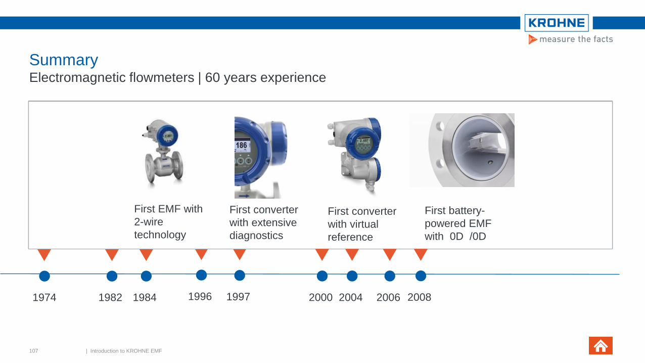
SummaryElectromagnetic flowmeters | 60 years experience
107 | Introduction to KROHNE EMF
1974
Stability & reliability
of EMF’s hugely
improved with a
pulsed direct
current with an
automatic zero
point correction
19841982
First micro-
processor-based
converter
enabling full
digital signal
processing &
digital filter
techniques
First EMF
with
ceramic
liner &
fused in
place
platinum
electrodes
1996 1997
First EMF with
capacitive plates
without wetted
electrodes
First EMF
for partly
filled pipes
First battery-
powered EMF
with 0D /0D
First converter
with virtual
reference
First converter
with extensive
diagnostics
First EMF with
2-wire
technology
2000 20082004 2006

SummaryElectromagnetic flowmeters | 60 years experience
OPTICHECK |
On-site verification tool
for KROHNE EMF’s
WATERFLUX 3070
First EMF with an integrated
P&T sensor
2014 2016
108 | Introduction to KROHNE EMF

SummaryOPTIFLUX | KROHNE electromagnetic flow sensors
Largest diameter range
DN2.5 to DN3000
Wide range of sensor connections
Flange connections
Nominal sizes & pressure ratings acc. to EN, ASME, ISO, JIS, AWWA
Sandwich connections
Hygienic connections
Special sensor constructions (on request)
Pressure ratings of up to 2500
Wide choice of sensor materials
SS, Duplex, 6mo
External coatings for offshore or subsoil installation
109 | Introduction to KROHNE EMF

SummaryOPTIFLUX | KROHNE electromagnetic flow sensors
Large choice of liners
A solution for every application with
polypropylene, EFTE, hard rubber, soft rubber, polyurethane, Rilsan,
ceramics
Flexibility in sizes
− Large diameter range
− Special ID’s & thicknesses
− Special constructions
Unique ceramics with fused-in electrodes
Rilsan coating for drinking water
Patented mesh for PFA liner
110 | Introduction to KROHNE EMF

SummaryOPTIFLUX | KROHNE electromagnetic flow sensors
Range of electrode options
Corrosion resistant & leak tight
Special designs: materials, retractable or pointed
111 | Introduction to KROHNE EMF

SummaryPrinciple of electromagnetic flow measurement
KROHNE Online Academy:
now presents the “Electromagnetic Flowmeters”
eLearning course
Click and register:
https://academy-online.krohne.com/
Free of charge for customers
3 Modules
History, measurement principles & construction
Material selection, sizing, special types, accuracy &
calibration
Installation, grounding & industries / applications
112 | Introduction to KROHNE EMF
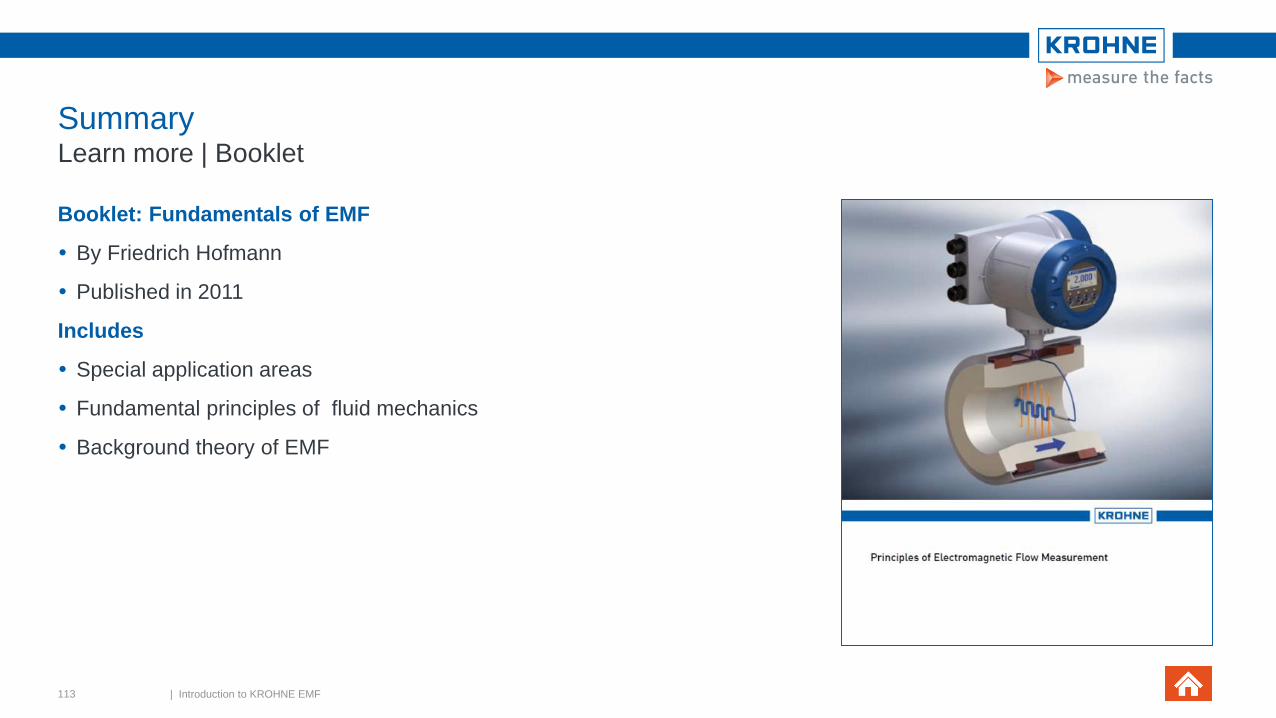
SummaryLearn more | Booklet
Booklet: Fundamentals of EMF
By Friedrich Hofmann
Published in 2011
Includes
Special application areas
Fundamental principles of fluid mechanics
Background theory of EMF
113 | Introduction to KROHNE EMF

Thank you for your attention!