
Introduction to Interfacial Enginering
15
NPTEL Chemical Engineering Interfacial Engineering Module 1: Lecture 1 Joint Initiative of IITs and IISc Funded by MHRD 1/15 Introduction to Interfacial Enginering Dr. Pallab Ghosh Associate Professor Department of Chemical Engineering IIT Guwahati, Guwahati–781039 India
Transcript of Introduction to Interfacial Enginering

NPTEL Chemical Engineering Interfacial Engineering Module 1: Lecture 1
Joint Initiative of IITs and IISc Funded by MHRD 1/15
Introduction to Interfacial Enginering
Dr. Pallab Ghosh
Associate Professor
Department of Chemical Engineering
IIT Guwahati, Guwahati–781039
India

NPTEL Chemical Engineering Interfacial Engineering Module 1: Lecture 1
Joint Initiative of IITs and IISc Funded by MHRD 2/15
Table of Contents
Section/Subsection Page No. 1.1.1 What is interfacial engineering? 3
1.1.2 Who are involved? 4
1.1.3 Some specific applications of interfacial engineering 4–9
1.1.3.1 Microelectronic devices 4
1.1.3.2 Hydrogen storage 6
1.1.3.3 Catalysis 7
1.1.3.4 Coatings 8
1.1.3.5 Enhanced petroleum recovery 8
1.1.3.6 Microfoams 9
1.1.4 Commonly observed interfacial phenomena 10–12
1.1.4.1 Capillary action 10
1.1.4.2 Marangoni effect 11
1.1.5 Important role of the interfaces 12
1.1.6 Specific surface area 13
1.1.7 Important points to remember 13
Exercise 14
Suggested reading 15

NPTEL Chemical Engineering Interfacial Engineering Module 1: Lecture 1
Joint Initiative of IITs and IISc Funded by MHRD 3/15
1.1.1 What is interfacial engineering?
Interface is the boundary between two phases where the properties or behavior of
material differ from those of the adjoining phases. Interfaces play an important role in
our daily life, and in the world around us. The recent developments in modern
technologies involve new materials and processes in which interfaces play a crucial role.
Fig. 1.1.1 illustrates the fluid–fluid and fluid–solid interfaces.
Fig. 1.1.1 Fluid–fluid and fluid–solid interfaces.
A gas–solid interface or a gas–liquid interface is often called a “surface”.
Some applications involving interfaces are:
Adhesives and coatings
Adsorption and ion exchange
Alloys, cement, ceramics, fibers, plastics, and powder metallurgy
Catalysis
Environmental pollution control
Food products
Liquid crystals
Medicines, pharamaceuticals and therapeutics
Microelectronic fabrication and imaging processes
Petroleum recovery and processing
Separation processes
Fluid 1
Fluid 2
Interface Fluid
Solid

NPTEL Chemical Engineering Interfacial Engineering Module 1: Lecture 1
Joint Initiative of IITs and IISc Funded by MHRD 4/15
The engineering involved in these varied applications is termed Interfacial Engineering.
1.1.2 Who are involved?
Biolotechnologists
Chemical engineers
Chemists
Electrical engineers
Environmental scientists
Materials scientists
Mechanical engineers
Physicists
Interfacial engineering is a cross-disciplinary subject in which the scientists and
engineers from several disciplines work together using their insights for the joint
development and optimization of performance of new materials and processes.
1.1.3 Some specific applications of interfacial engineering
A few specific applications of interfacial engineering are discussed here which
have potentials in the future.
1.1.3.1 Microelectronic devices
Silicon semiconductors have grown tremendously in terms of memory and logic.
Every four years produce an order of magnitude improvement in the performance,
keeping the cost almost constant, and sometimes lower.
As the physical limits of the conventional silicon chips are being approached,
researchers are seeking the next small thing in electronics through chemistry. By
making devices from small groups of molecules, researchers may be able to pack
computer chips with billions of transistors, more than 10 times as many as the
current technology can achieve.
Researchers in molecular-electronics think that it is possible to make complex
circuitry by utilizing DNA’s ability to recognize molecules and self-assemble.

NPTEL Chemical Engineering Interfacial Engineering Module 1: Lecture 1
Joint Initiative of IITs and IISc Funded by MHRD 5/15
They hope to use DNA as a template for crafting metallic wiring, or even to wire
circuits with strands of DNA itself.
Makers of computer chips are concerned with the wavelength-limits of light. As
the wavelength of the light is reduced, smaller features can be printed on the chip.
As a general rule of thumb, a given wavelength can make features about half its
length. Typically, light of 248 nm wavelength was used in the past in optical
lithography devices, and the smallest features that could be made by these devices
were about 120 nm. Chipmakers are trying to build devices which use much
shorter wavelengths (e.g., 157 nm). Features as small as 80 nm have already been
created on silicon wafers. Researchers expect that the technology will be able to
turn out features as small as 10 nm. A futuristic design of all-optical chip is
shown in Fig. 1.1.2.
Fig. 1.1.2 Photonic crystal micropolis (source: G. A. Ozin and A. C. Arsenault, Nanochemistry, RSC Publishing, Cambridge, 2005; reproduced by permission
from Macmillan Publishers, 2005).
This chip is believed to be the chip of the future. It comprises of integrated
microphotonic crystals with 1D, 2D, or 3D periodicity. Coupling of light from
waveguide to photonic crystal may be accomplished via extrinsic defects built
into the photonic lattice. Integrated photonic crystal components on all-optical
chips are envisioned to function as low threshold lasers, wavelength division
multiplexes, wavelength dispersion compensators, and switches.
Very small light-emitting diodes (LED) can be made from the nanowires, as
shown in Fig. 1.1.3.

NPTEL Chemical Engineering Interfacial Engineering Module 1: Lecture 1
Joint Initiative of IITs and IISc Funded by MHRD 6/15
Fig. 1.1.3 World’s smallest light-emitting diode (source: D. H. Cobden, Nature, 409, 32, 2001; reproduced by permission from Macmillan Publishers, 2001).
A nanowire is grown from two reagents (red and yellow dots) with the help of a
metal catalyst particle (orange), as shown in Fig. 1.1.3 (a). The nanowire is
assembled between two metal electrodes using an electric field gradient, as shown
in Fig. 1.1.3 (b), and a p-doped and an n-doped nanowire are crossed to form a
nanoscale light-emitting diode, as shown in Fig. 1.1.3 (c). When a current is
passed between them, electrons and holes are injected across the junction and
recombine to emit light.
1.1.3.2 Hydrogen storage
Safe storage of hydrogen for fueling motor vehicles and driving portable
electronics can be made employing the metal-organic frameworks (MOFs). Lightweight
and compact materials are being developed that can rapidly adsorb and desorb large
amounts of hydrogen under ambient temperature and pressure conditions. For
coordination framework to meet this challenge, they will need to satisfy the storage
requirements and the structural integrity must be maintained on removing the template or
occluded water or solvent. A candidate for this role is the MOF, Zn4O(BDC)3 where
BDC is 1,4-benzene-dicarboxylate (Fig. 1.1.4). It has a sturdy cubic open-framework
structure with a very large surface area (2500–3000 m2/g), and its thermal stability is also
good viz. 600–700 K.
In Fig. 1.1.4, the choice of the organic group provides control over the size of the
cubic unit cell, and concomitantly the adsorption capacity of the material. The empty
volume is shown by the central spheres.

NPTEL Chemical Engineering Interfacial Engineering Module 1: Lecture 1
Joint Initiative of IITs and IISc Funded by MHRD 7/15
Fig. 1.1.4 Hydrogen storage MOF, Zn4O(RDC)3 (source: N. L. Rosi, J. Eckert, M.
Eddaoudi, D. T. Vodak, J. Kim, M. O’Keeffe, and O. M. Yaghi, Science, 300, 1127, 2003; reproduced by permission from The American Association for the Advancement of
Science, 2003).
1.1.3.3 Catalysis
Solid catalysts are made of porous solids. As per the IUPAC classification of the
porous solids, pores having diameter in the range of 2 nm and below are called
micropores, those in the range of 2 nm to 50 nm are termed mesopores, and those above
50 nm are macropores. The distribution of size, shape and volume of the void spaces in
porous materials govern their ability to perform the desired function in a particular
application. The science and engineering of porous materials deal with the methodology
to create uniformity in pore size, shape and volume. The first synthesis of a crystalline
microporous material with uniform pores larger than 1 nm was reported in the late 1980s.
A microporous material, VPI-5, is shown in the Fig. 1.1.5.
Fig. 1.1.5 Pore characteristics in VPI-5 (source: M. E. Davis, Nature, 417, 813, 2002; reproduced by permission from Macmillan Publishers, 2002).
The line segments represent oxygen atoms that bridge between two tetrahedral atoms.
The aluminophosphate, VPI-5, has a pore size of 1.2 nm. The pores are uniform-diameter
channels having circular cross-section. The material has 30% void fraction.
NPTEL Chemical Engineering Interfacial Engineering Module 1: Lecture 1
Joint Initiative of IITs and IISc Funded by MHRD 8/15
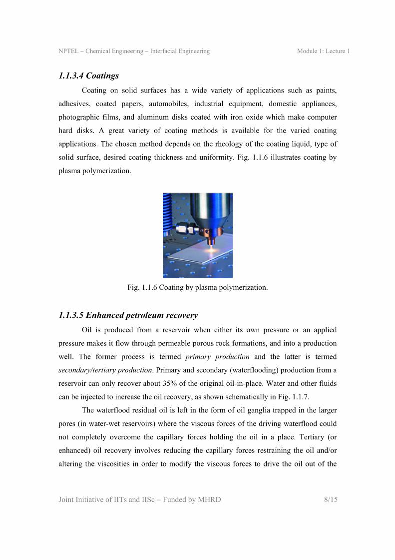
1.1.3.4 Coatings
Coating on solid surfaces has a wide variety of applications such as paints,
adhesives, coated papers, automobiles, industrial equipment, domestic appliances,
photographic films, and aluminum disks coated with iron oxide which make computer
hard disks. A great variety of coating methods is available for the varied coating
applications. The chosen method depends on the rheology of the coating liquid, type of
solid surface, desired coating thickness and uniformity. Fig. 1.1.6 illustrates coating by
plasma polymerization.
Fig. 1.1.6 Coating by plasma polymerization.
1.1.3.5 Enhanced petroleum recovery
Oil is produced from a reservoir when either its own pressure or an applied
pressure makes it flow through permeable porous rock formations, and into a production
well. The former process is termed primary production and the latter is termed
secondary/tertiary production. Primary and secondary (waterflooding) production from a
reservoir can only recover about 35% of the original oil-in-place. Water and other fluids
can be injected to increase the oil recovery, as shown schematically in Fig. 1.1.7.
The waterflood residual oil is left in the form of oil ganglia trapped in the larger
pores (in water-wet reservoirs) where the viscous forces of the driving waterflood could
not completely overcome the capillary forces holding the oil in a place. Tertiary (or
enhanced) oil recovery involves reducing the capillary forces restraining the oil and/or
altering the viscosities in order to modify the viscous forces to drive the oil out of the

NPTEL Chemical Engineering Interfacial Engineering Module 1: Lecture 1
Joint Initiative of IITs and IISc Funded by MHRD 9/15
pores. The addition of a surfactant can reduce the interfacial tension and the capillary
forces. It can also alter the wettability of the reservoir rock.
Fig. 1.1.7 Displacement of oil in a petroleum reservoir by chemical flooding using
surfactants (Source: L. E. Schramm, Emulsions, Foams, and Suspensions, Wiley-VCH, Weinheim, 2005; reproduced by permission from Wiley-VCH, 2005).
1.1.3.6 Microfoams
Microfoams, or colloidal gas aphrons, are dispersion of aggragates of very small
spherical foam bubbles in aqueous solution (Fig. 1.1.8). The size of the bubbles is 50–
100 m. Techniques for preparation and functionalization of microfoams with
surfactants, nanoparticles, pharmaceuticals and bioactive agents is under progress.
Fig. 1.1.8 Photomicrograph of a micro foam (source: L. E. Schramm, Emulsions, Foams, and Suspensions, Wiley-VCH, Weinheim, 2005; reproduced by permission from Wiley-
VCH, 2005).

NPTEL Chemical Engineering Interfacial Engineering Module 1: Lecture 1
Joint Initiative of IITs and IISc Funded by MHRD 10/15
The microfoams are useful in oil recovery, microencapsulation, materials processing,
food technology, therapeutics, and imaging. They are finding extensive use in wastewater
treatment.
1.1.4 Commonly observed interfacial phenomena
1.1.4.1 Capillary action
This phenomenon is responsible for the spontaneous rise of water through the
trunk of the tree, or transport of water from the wet soil to the dry areas. It can be
demonstrated quite easily. Suppose that a capillary is dipped in a vessel containing water.
It will be observed that the liquid level inside the tube is higher than the liquid level
outside. This phenomenon is known as capillary rise (Fig. 1.1.9). For some liquids, such
as mercury, the reverse happens and capillary depression is observed.
Fig. 1.1.9 Capillary action.
The reason behind capillary rise is the adhesive force between the liquid and the solid
material, and the surface tension of the liquid. The upward movement of the liquid
column is driven by surface tension. The liquid continues to rise until the weight of the
liquid column balances the upward pull. It can be shown easily that water will rise about
30 mm above the airwater interface inside a 1 mm diameter glass tube. Water will rise
higher if a smaller-diameter capillary is used. The capillary action has been used in
advanced scientific analysis such as thin layer chromatography. It has also been utilized
to manufacture garments used for sports and rigorous outdoor activities.

NPTEL Chemical Engineering Interfacial Engineering Module 1: Lecture 1
Joint Initiative of IITs and IISc Funded by MHRD 11/15
1.1.4.2 Marangoni effect
The transport of liquid due to the gradient in surface tension is known as
Marangoni effect (named after Italian physicist Carlo Marangoni who published this
effect circa 1865). A classic example of the Marangoni effect is tears-of-wine (Fig.
1.1.10). The surface tension gradient is caused by the gradient in the concentration of
ethanol in this case. It is also known as wine legs.
This phenomenon was first scientifically interpreted by James Thomson in 1855.
When a wine of high alcohol-content is taken in a glass, a ring of clear liquid is formed
in the upper part of the glass. This is caused by the induced flow of liquid driven by the
surface tension gradient, and capillary action.
Fig. 1.1.10 Tears-of-wine.
Alcohol exhibits surface activity when it is added to water. For example, the surface
tension of water is reduced to less than half its original value when a small amount of
ethyl alcohol is added to it (the surface tension of water is 72.5 mN/m at 298 K whereas
the same for ethyl alcohol is 23 mN/m). Capillary action forces the liquid to climb along
the glass wall. Therefore, a thin liquid film is formed on the glass wall. However, alcohol
has higher vapor pressure and lower boiling point than water. As a result, it evaporates
faster and increases the surface tension of the liquid in the film. This creates a surface
tension gradient in the film, which draws further liquid from the bulk of the wine,
because the wine has lower surface tension due to its higher alcohol-content. In this
process, a considerable amount of the liquid climbs up along the wall of the glass. After
some time, the liquid in the film begins to fall downward due to gravity. These falling

NPTEL Chemical Engineering Interfacial Engineering Module 1: Lecture 1
Joint Initiative of IITs and IISc Funded by MHRD 12/15
streams manifest themselves as the ‘tears of wine’. This phenomenon is mainly related to
the alcohol-content of the wine. Apparently, if evaporation is reduced, tears would
subside, which is actually observed when the glass is covered.
The Marangoni effect is believed to be a very important factor in the stabilization
of foams and emulsions.
1.1.5 Important role of the interfaces
In many applications where the role of interfaces are important, a large interfacial
area is involved. Small particles have a high surface area per unit mass. Porous materials
with very fine pores have a large internal surface area. That is the key feature of
enormous importance.
Example 1.1.1: A spherical particle of 2 cm diameter is broken uniformly into a large
number of tiny spheres such that the diameter of each of the new particles is 71 10 m.
What is the total surface area of these particles?
Solution: The surface area of a spherical particle of 2 cm diameter is,
2 31.26 10 A πD m2
The volume of the sphere is, 3
6πD
V
If the diameter of the new particles be d and their number be N then,
3 3
6 6
πD πdV N
Therefore, the number of particles is given by,
33 215
72 10
8 101 10
DN
d
Therefore, the total surface area of the new particles is,
22 15 7tot 8 10 1 10 251.2 A Nπd π m2
NPTEL Chemical Engineering Interfacial Engineering Module 1: Lecture 1
Joint Initiative of IITs and IISc Funded by MHRD 13/15
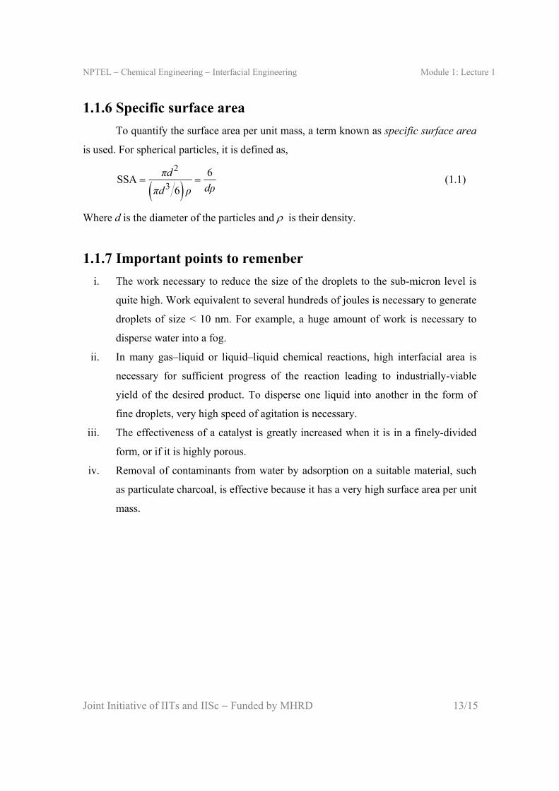
1.1.6 Specific surface area
To quantify the surface area per unit mass, a term known as specific surface area
is used. For spherical particles, it is defined as,
2
3
6SSA
6
πd
dρπd ρ (1.1)
Where d is the diameter of the particles and is their density.
1.1.7 Important points to remenber
i. The work necessary to reduce the size of the droplets to the sub-micron level is
quite high. Work equivalent to several hundreds of joules is necessary to generate
droplets of size < 10 nm. For example, a huge amount of work is necessary to
disperse water into a fog.
ii. In many gas–liquid or liquid–liquid chemical reactions, high interfacial area is
necessary for sufficient progress of the reaction leading to industrially-viable
yield of the desired product. To disperse one liquid into another in the form of
fine droplets, very high speed of agitation is necessary.
iii. The effectiveness of a catalyst is greatly increased when it is in a finely-divided
form, or if it is highly porous.
iv. Removal of contaminants from water by adsorption on a suitable material, such
as particulate charcoal, is effective because it has a very high surface area per unit
mass.
NPTEL Chemical Engineering Interfacial Engineering Module 1: Lecture 1
Joint Initiative of IITs and IISc Funded by MHRD 14/15
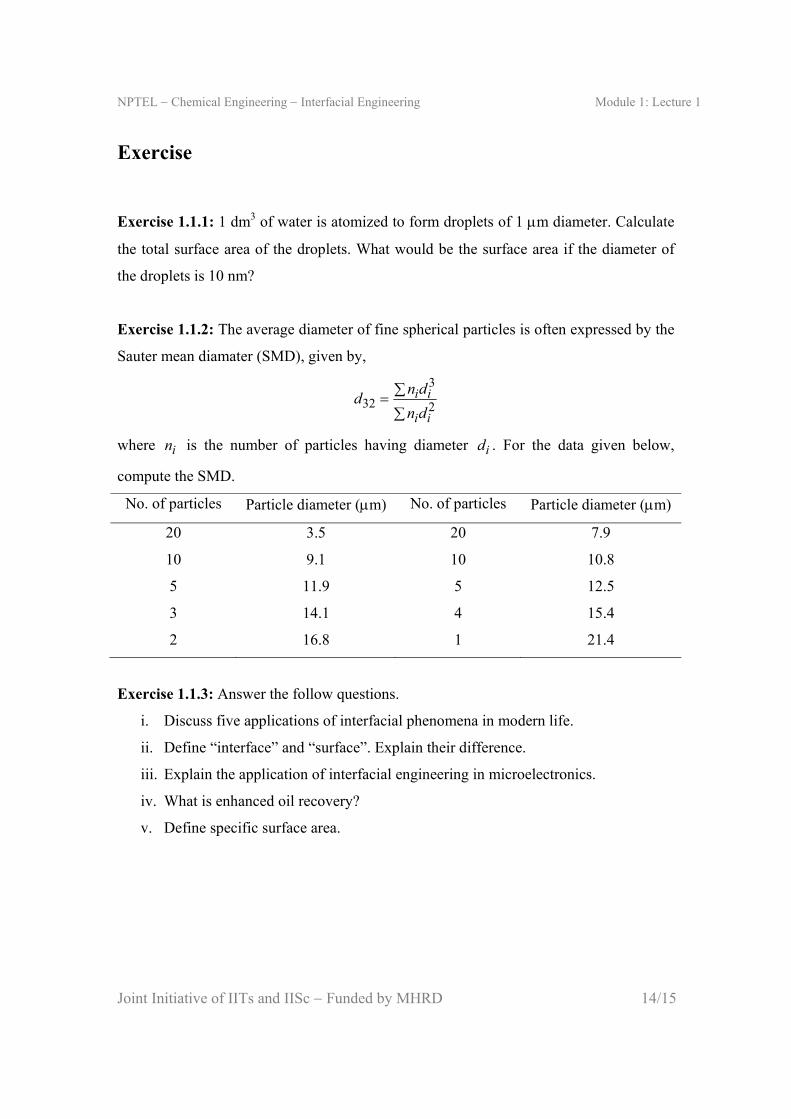
Exercise
Exercise 1.1.1: 1 dm3 of water is atomized to form droplets of 1 m diameter. Calculate
the total surface area of the droplets. What would be the surface area if the diameter of
the droplets is 10 nm?
Exercise 1.1.2: The average diameter of fine spherical particles is often expressed by the
Sauter mean diamater (SMD), given by,
3
32 2i i
i i
n dd
n d
where in is the number of particles having diameter id . For the data given below,
compute the SMD.
No. of particles Particle diameter (m) No. of particles Particle diameter (m)
20 3.5 20 7.9
10 9.1 10 10.8
5 11.9 5 12.5
3 14.1 4 15.4
2 16.8 1 21.4
Exercise 1.1.3: Answer the follow questions.
i. Discuss five applications of interfacial phenomena in modern life.
ii. Define “interface” and “surface”. Explain their difference.
iii. Explain the application of interfacial engineering in microelectronics.
iv. What is enhanced oil recovery?
v. Define specific surface area.

NPTEL Chemical Engineering Interfacial Engineering Module 1: Lecture 1
Joint Initiative of IITs and IISc Funded by MHRD 15/15
Suggested reading
Textbooks
P. Ghosh, Colloid and Interface Science, PHI Learning, New Delhi, 2009,
Chapters 1 & 11.
R. J. Stokes and D. F. Evans, Fundamentals of Interfacial Engineering, Wiley-
VCH, New York, 1997, Chapter 1.
Reference books
J. Lyklema, Fundamentals of Interface and Colloid Science, Vol. 1, Academic
Press, London, 1991, Chapter 1.
L. E. Schramm, Emulsions, Foams, and Suspensions, Wiley-VCH, Weinheim,
2005, Chapter 11.
Journal articles
D. H. Cobden, Nature, 409, 32 (2001).
J. D. Joannopoulos, P. R. Villeneuve, and S. H. Fan, Nature, 386, 143 (1997).
M. E. Davis, Nature, 417, 813 (2002).
N. L. Rosi, J. Eckert, M. Eddaoudi, D. T. Vodak, J. Kim, M. O’Keeffe, and O. M.
Yaghi, Science, 300, 1127 (2003).
R. F. Service, Science, 293, 782 (2001).


