Introduction to Embedded Systems Rabie A. Ramadan [email protected] 8.
97
Introduction to Embedded Systems Rabie A. Ramadan [email protected] http:// www.rabieramadan.org /classes/2014/embedded/ 8
-
Upload
michael-morris -
Category
Documents
-
view
224 -
download
0
Transcript of Introduction to Embedded Systems Rabie A. Ramadan [email protected] 8.

Introduction to Embedded Systems
Rabie A. [email protected]
http://www.rabieramadan.org/classes/2014/embedded/
8

Microcontrollers

What is a Microcontroller?
A microcontroller is a kind of miniature computer that found in all kinds of gizmos
Generally speaking, if a device has buttons and a digital display, chances are it also has a programmable microcontroller brain.

Microcontrollers cont.
Microcontrollers are 'single chip' computers specifically designed to:
• Read input devices, such as buttons and sensors• Process data or information• Control output devices, such as lights, displays, motors
and speakers

Embedded Control
Microcontrollers are placed in devices, or embedded, for operation and control.
Can you name other devices in your life that have embedded control?

Microprocessor vs. Microcontroller A microprocessor is the “brain” of a computer system
Generally referred to as the central processing unit (CPU), the microprocessor by itself is practically useless
To be useful, one must have means of communicating with it using input and output devices
One must also add memory (ROM and RAM) so that the system can be programmed.

Microprocessor vs. Microcontroller Cont. A microcontroller is a computer chip designed for control-
oriented applications Unlike ordinary microprocessors, microcontrollers have built-in
features that make them operate almost independent of additional circuitry
This is possible because microcontrollers contain things like • memory (ROM, EPROM, RAM, etc)• input and output ports• timers• serial and parallel communication capability• analog-to-digital converters

The BASIC Stamp The BASIC Stamp embeds a microcontroller, the
PIC16C57, on a module to make programming and use very simple, yet very powerful.
Additional components on the module provide everything needed to systems and applications, like robotics.

Microcontroller There are two branches in the ongoing evolution of the
microprocessor.• CPUs for the personal computer and workstation
industry, where the main constraints are high speed and large word size (32 and 64 bits)
• Development of the microcontroller, which is a single IC containing specialized circuits and functions that are applicable to mechatronic system design. • Examples of microcontrollers are Microchip’s PIC,
Motorola’s 68HC11, and Intel’s 8096
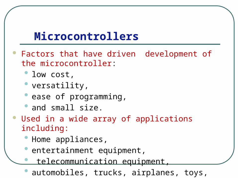
Microcontrollers Factors that have driven development of the microcontroller:
• low cost, • versatility, • ease of programming,• and small size.
Used in a wide array of applications including: • Home appliances, • entertainment equipment,• telecommunication equipment, • automobiles, trucks, airplanes, toys, and office equipment.

typical full-featured microcontroller
Microcontroller programming
Microcontroller manufacturers offer programming devices that can download a compiled machine code file from a PC directly to the EEPROM of the microcontroller,
usually via the PC serial port and special-purpose pins on the microcontroller.
These pins can usually be used for other purposes once the device is programmed.

Microcontroller I/O
The digital I/O ports allow binary data to be transferred to and from the microcontroller using external pins on the IC.
These pins can be used to read the state of switches and on-off sensors, to interface to external analog-to-digital and digital-to-analog converters, to control digital displays, and to control on-off actuators.
The I/O ports can also be used to transmit signals to and from other microcontrollers to coordinate various functions.

Microcontroller communication Standards
There are various standards or protocols for serial communication : • SPI (serial peripheral interface), • I2C (inter-integrated circuit), • UART (universal asynchronous receiver-transmitter), • and USART (universal synchronous asynchronous receiver-
transmitter).

Microcontroller capabilities microcontroller clock speeds are slower than those used for
microcomputers. For some applications, a selected microcontroller may not have
enough speed or memory to satisfy the needs of the application Fortunately , microcontroller manufacturers usually provide a
wide range of products to accommodate different applications. When more memory or I/O capability is required, the
functionality of the microcontroller can be expanded with additional external components
PIC PIC is an acronym for peripheral interface controller
The phrase Microchip uses to refer to its line of microcontrollers.
Microchip offers a large and diverse family of low-cost PIC products.

Class Discussion


PIC16F84 Properties The PIC16F84 is:
• an 8-bit CMOS microcontroller where data bus is 8 bits wide
• 1792 bytes of flash EEPROM program memory,• The 1792 bytes of program memory are subdivided into 14-
bit words, because machine code instructions are 14 bits wide.
• 68 bytes of RAM data memory, • 64 bytes of non-volatile EEPROM data memory. • can be driven at a clock speed up to 10 MHz but is typically
driven at 4 MHz

Watch Dog Timer
A useful special purpose timer It is a count-down timer that, when activated, needs to
be continually reset by the running program. If the program fails to reset the watch-dog timer before
it counts down to 0, the PIC will automatically reset itself.
In a critical application, you might use this feature to have the microcontroller reset if the software gets caught in an unintentional endless loop

The PIC16F84 is packaged on an 18-pin that has the pin schematic

Pin Naming
13 I/O lines, called bidirectional lines because each can be individually configured in software as an input or output.

The program is written and uploaded into microcontroller
If the program is written in assembly language, the PC must have software called a cross-assembler that generates machine code for the microcontroller

PIC programs can be written in a form of BASIC called PicBasic Pro.
The PicBasic Pro complier can compile these programs,
producing their assembly language equivalents,
assembly code can then be converted to hexadecimal machine code (hex code) that can be downloaded directly to the PIC flash EEPROM through a programming device attached to a PC.

PICBasic Example

The Previous Example using the concept of Polling For more complex applications, polling may not be suitable An alternative approach is to use an interrupt. some inputs are connected to special input lines, designated as
interrupts. To detect interrupts, two specific registers on the PIC must be
initialized correctly. • the option register (OPTION_REG) and • the interrupt control register (INTCON).

More details on the PIC16F84 http://highered.mcgraw-hill.com
/sites/dl/free/0072402415/55328/alc_ch07.pdf

Choosing a microcontroller

Criteria for choosing a microcontroller
Features of the 8051

Comparison of 8051 Family Members

The 8051 Microcontroller architecture
32

1. Meeting the computing needs of the task efficiently and cost effectively• speed, the amount of ROM and RAM, the number of I/O
ports and timers, size, packaging, power consumption• easy to upgrade• cost per unit
2. Availability of software development tools• assemblers, debuggers, C compilers, emulator, simulator,
technical support
3. Wide availability and reliable sources of the microcontrollers.
Three criteria in Choosing a Microcontroller

The 8051 microcontroller A Harvard architecture (separate instruction/data
memories) Single chip microcontroller (µC) Developed by Intel in 1980 for use in
embedded systems. Today largely superseded by a vast range of faster
and/or functionally enhanced 8051-compatible devices manufactured by more than 20 independent manufacturers

Block Diagram
CPU
On-chip RAM
On-chip ROM for program code
4 I/O Ports
Timer 0
Serial PortOSC
Interrupt Control
External interrupts
Timer 1
Timer/Counter
Bus Control
TxD RxDP0 P1 P2 P3
Address/Data
Counter Inputs

Feature 8051 8052 8031ROM (program space in bytes) 4K 8K 0KRAM (bytes) 128 256 128Timers 2 3 2I/O pins 32 32 32 Serial port 1 1 1
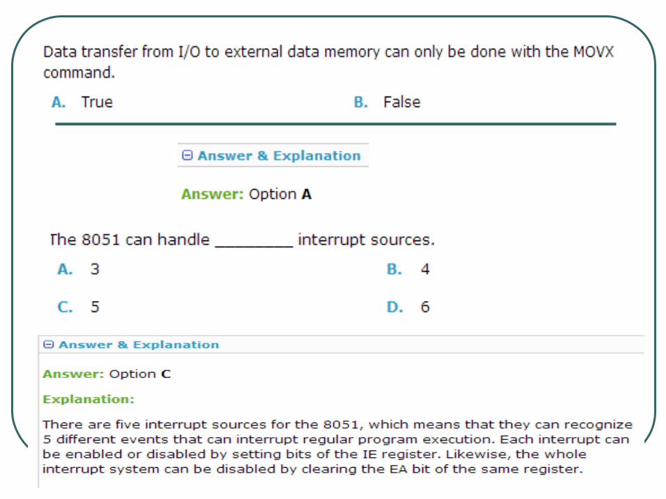
Interrupt sources 6 8 6
Comparison of the 8051 Family Members


Pin Description of the 80511234567891011121314151617181920
4039383736353433323130292827262524232221
P1.0P1.1P1.2P1.3P1.4P1.5P1.6P1.7RST
(RXD)P3.0(TXD)P3.1
(T0)P3.4(T1)P3.5
XTAL2XTAL1
GND
(INT0)P3.2(INT1)P3.3
(RD)P3.7(WR)P3.6
VccP0.0(AD0)P0.1(AD1)P0.2(AD2)P0.3(AD3)P0.4(AD4)P0.5(AD5)P0.6(AD6)P0.7(AD7)EA/VPPALE/PROGPSENP2.7(A15)P2.6(A14)P2.5(A13)P2.4(A12)P2.3(A11)P2.2(A10)P2.1(A9)P2.0(A8)
8051(8031)
Pins of 8051 ( 1/4 )
Vcc ( pin 40 ):• Vcc provides supply voltage to the chip. • The voltage source is +5V.
GND ( pin 20 ): ground XTAL1 and XTAL2 ( pins 19,18 ):
• These 2 pins provide external clock.• Way 1 : using a quartz crystal oscillator• Way 2 : using a TTL oscillator

Pins of 8051 ( 2/4 )
RST ( pin 9 ): reset• It is an input pin and is active high ( normally low ) .
• The high pulse must be high at least 2 machine cycles.• It is a power-on reset.
• Upon applying a high pulse to RST, the microcontroller will reset and all values in registers will be lost.
• Reset values of some 8051 registers • Way 1 : Power-on reset circuit • Way 2 : Power-on reset with debounce

Pins of 8051 ( 3/4 )
/EA ( pin 31 ): external access• There is no on-chip ROM in 8031 and 8032 .• The /EA pin is connected to GND to indicate the code is
stored externally.• /PSEN & ALE are used for external ROM.• For 8051, /EA pin is connected to Vcc.• “/” means active low.
/PSEN ( pin 29 ): program store enable• This is an output pin.
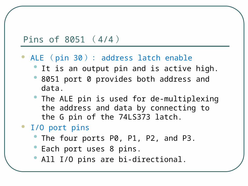
Pins of 8051 ( 4/4 )
ALE ( pin 30 ): address latch enable• It is an output pin and is active high.• 8051 port 0 provides both address and data.• The ALE pin is used for de-multiplexing the address and
data by connecting to the G pin of the 74LS373 latch. I/O port pins
• The four ports P0, P1, P2, and P3.• Each port uses 8 pins.• All I/O pins are bi-directional.

Figure 4-2 (a). XTAL Connection to 8051
Using a quartz crystal oscillator We can observe the frequency on the XTAL2 pin.

XTAL Connection to an External Clock Source
Using a TTL oscillator XTAL2 is unconnected.
NC
EXTERNALOSCILLATORSIGNAL
XTAL2
XTAL1
GND

Pins of I/O Port
The 8051 has four I/O ports• Port 0 ( pins 32-39 ): P0 ( P0.0 ~ P0.7 )• Port 1 ( pins 1-8 ) : P1 ( P1.0 ~ P1.7 )• Port 2 ( pins 21-28 ): P2 ( P2.0 ~ P2.7 )• Port 3 ( pins 10-17 ): P3 ( P3.0 ~ P3.7 )• Each port has 8 pins.
• Named P0.X ( X=0,1,...,7 ) , P1.X, P2.X, P3.X• These 8 bits form a byte.
Each port can be used as input or output (bi-direction).

CPU timing Most 8051 instructions are executed in one cycle.
MUL (multiply) and DIV (divide) are the only instructions that take more than two cycles to complete (four cycles)
Normally two code bytes are fetched from the program memory during every machine cycle.
The only exception to this is when a MOVX instruction is executed. MOVX is a one-byte, 2-cycle instruction that accesses external data memory.

8051 microcontroller features
47

8051 microcontroller instruction set
48

Data Transfer Instructions
49

Bit and Byte Manipulations and Logic instructions
50

Arithmetic Instructions
51

Program Flow Control Instructions
52

Interrupt Flow Control Instructions
53
54

55

56
57

58

59

60

61

62

63

Sensors and Actuators

Definitions and Background
65
Sensing: • Is a technique used to gather information about a physical object or
process, including the occurrence of events (i.e., changes in state such as a drop in temperature or pressure).
Sensor: • An object performing such a sensing task• Converts energy of the physical worlds into electrical signal. • Sometimes named “Transducer” converts energy from one form to
another.

Definitions and Background
66
Examples on remote sensors:• eyes: capture optical information (light)• ears: capture acoustic information (sound)• nose: captures olfactory information (smell)• skin: captures tactile information (shape, texture)
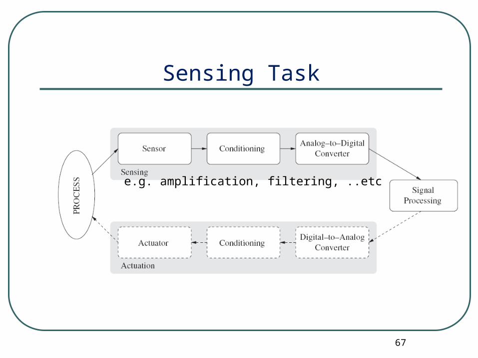
Sensing Task
67
e.g. amplification, filtering, ..etc

An example of a sensor: Passive infrared
PIR is a differential sensor: detects target as it crosses the
“beams” produced by the optic

PIR signal: Amplitude
Human 3 mph @ 10m
Car 20-25 mph @ 25m

Communication Unit
Sensing Unit
Sensors
ADC
Processing Unit
Processor
Storage
Power Unit
Mobility Support Unit Location Finding Unit
What is a Smart Sensor Node?

Node’s Responsibilities
71
Data Collection
In-Network Analysis
Data Fusion
Decision Making

Sensors Classification
72
Type Examples
Temperature Thermistors, thermocouples
Pressure Pressure gauges, barometers, ionization gauges
Optical Photodiodes, phototransistors, infrared sensors, CCD sensors
Acoustic Piezoelectric resonators, microphones
Mechanical Strain gauges, tactile sensors, capacitive diaphragms, piezoresistive cells
Motion, vibration Accelerometers, mass air flow sensors
Position GPS, ultrasound-based sensors, infrared-based sensors, inclinometers
Electromagnetic Hall-effect sensors, magnetometers
Chemical pH sensors, electrochemical sensors, infrared gas sensors
Humidity Capacitive and resistive sensors, hygrometers, MEMS-based humidity sensors
Radiation Ionization detectors, Geiger-Mueller counters
Physical property to be monitored determines type of required sensor

Other Classifications Power supply:
• active sensors require external power, i.e., they emit energy (microwaves, light, sound) to trigger response or detect change in energy of transmitted signal (e.g., electromagnetic proximity sensor)
• passive sensors detect energy in the environment and derive their power from this energy input .
Electrical phenomenon:• resistive sensors use changes in electrical resistivity (ρ) based on physical
properties such as temperature • capacitive sensors use changes in capacitor dimensions or permittivity (ε)
based on physical properties • inductive sensors rely on the principle of inductance (electromagnetic force is
induced by fluctuating current)• piezoelectric sensors rely on materials (crystals, ceramics) that generate a
displacement of charges in response to mechanical deformation

Sample Sensor Hardware: Berkeley motes
74
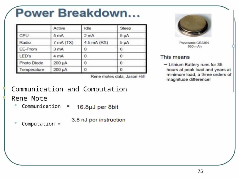
75
Communication and Computation Rene Mote
• Communication =
• Computation =

What Do We Have
76
TelosB (Taroko/TmoteSky/TIP700CM)• Original design: UC Berkeley
Crossbow TelosB
Moteiv Tmote Sky
CHNDS Taroko
Maxfor TIP700CM

Crossbow
77
Original design: UC Berkeley• Commercial product: Crossbow
• Other products from Crossbow• Cricket• Imote2• IRIS
Mica2MicaZ
IRISImoteCricket

Others (Research)
78
BTnode (ETH Zurich)• Commercialized
XYZ (Yale University)
MSB (Freie Universitat Berlin)• Modular Sensor Board (MSB)

Others (Commercial)
79
Dustnetworks (spun out of UC Berkeley)
iDwaRF – NodeBoard
Worldsens – WSN430

Others (Industrial Control)
80
Accsense
MicroStrain
Sensicast

Now !
81
Taroko
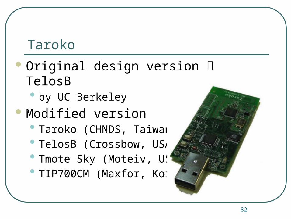
82
Original design version TelosB• by UC Berkeley
Modified version• Taroko (CHNDS, Taiwan)• TelosB (Crossbow, USA)• Tmote Sky (Moteiv, USA)• TIP700CM (Maxfor, Korea)

On Taroko
83
• Microcontroller • TI (Texas Instruments) MSP430F1611
Radio• TI Chipcon CC2420• 250kbps, 2.4GHz
USB interface 8M-bit flash memory Extension connectors Optional sensors• Light, Humidity and Temperature

Power Efficiency Efficient Hardware
• Operate at low voltages and low current• Selectable Power States : Off, Sleep, Active
Efficient Software• Fine-grained control of hardware• Aggregate data / Utilize wireless broadcast
Low Duty Cycle Operation• Sleep –> majority of the time• Wakeup –> quickly start processing• Active –> minimize work & return to sleep


TinyOS
Disclaimer: a. Information included in this slides came from multiple sources. We have tried
our best to cite the sources. b. The slides should be used only for academic purposes (e.g., in teaching a class)
and should not be used for commercial purposes.

Need of TinyOS
TinyOS 89
Problems with traditional OS• Multithreaded Architecture not useful• Large Memory Footprint• Does not help to conserve energy and power
Requirements for Embedded Systems • Efficient utilization of energy and power• Small Footprint• Should support diversity in design and usage• More emphasis on Concurrent execution

Introduction to TinyOS
TinyOS 90
TinyOS began as a collaboration between University of California, Berkeley and Intel Research.
It is a free open source operating system designed for wireless sensor networks.
It is an embedded operating system written in NesC
It features a component based architecture.

TinyOS as a Solution
TinyOS 91
Component based architecture allows frequent changes while still keeping the size of code minimum.
Event based execution model means no user/kernel boundary and hence supports high concurrency.
It is power efficient as it makes the sensors sleep as soon as possible.
Has small footprint as it uses a non-preemtable FIFO task scheduling.

TinyOS Models
TinyOS 92
TinyOS models-• Data Model• Thread Model• Programming Model• Component Model• Network Model
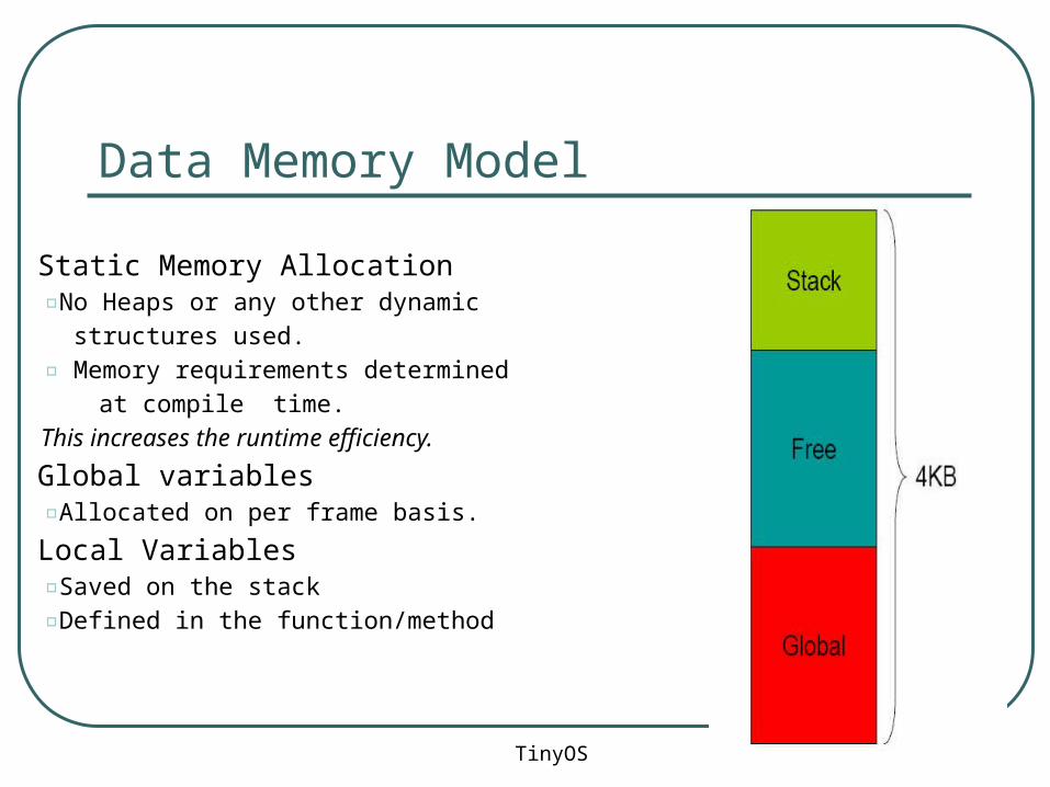
Data Memory Model
TinyOS 93
• Static Memory Allocation▫No Heaps or any other dynamic
structures used.
▫ Memory requirements determined
at compile time.
This increases the runtime efficiency.
• Global variables▫Allocated on per frame basis.
• Local Variables▫Saved on the stack
▫Defined in the function/method
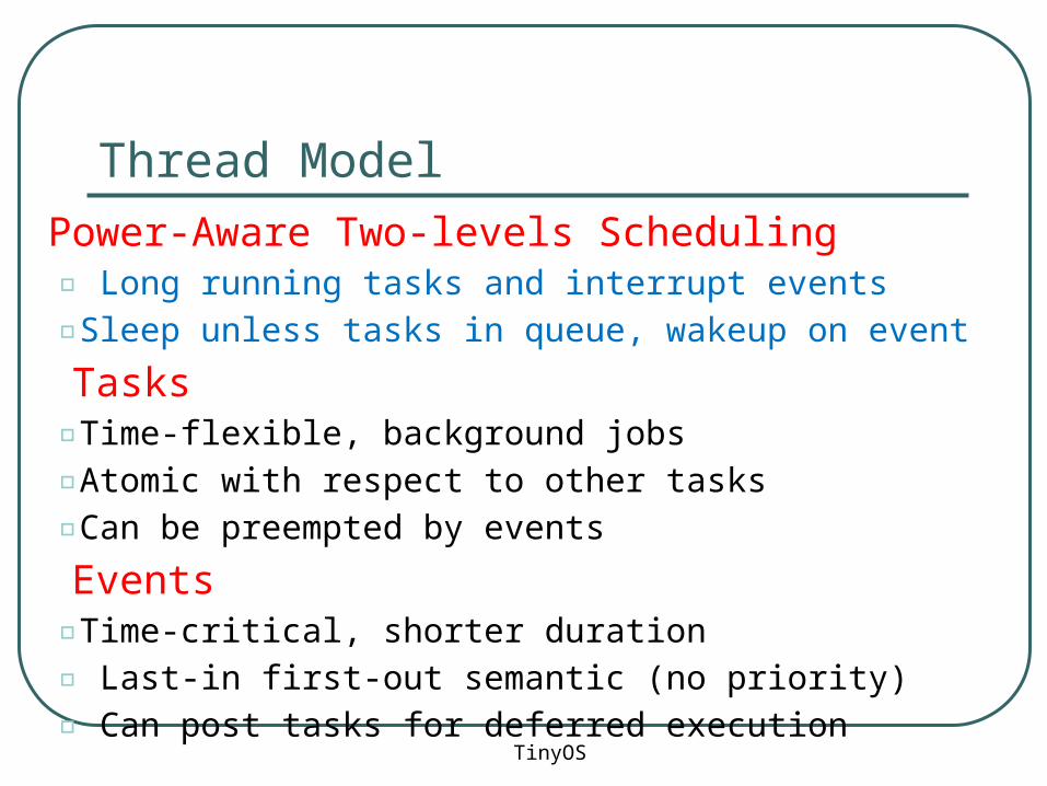
Thread Model
TinyOS 94
• Power-Aware Two-levels Scheduling▫ Long running tasks and interrupt events
▫Sleep unless tasks in queue, wakeup on event
• Tasks▫Time-flexible, background jobs
▫Atomic with respect to other tasks
▫Can be preempted by events
• Events▫Time-critical, shorter duration
▫ Last-in first-out semantic (no priority)
▫ Can post tasks for deferred execution

Programming Model
TinyOS 95
Separation construction/composition Construction of Modules
• Modules implementation similar to C coding• Programs are built out of components• Each component specifies an interface• Interfaces are “hooks” for wiring components
Composition of Configurations• Components are statically wired together• Increases programming efficiency (code reuse) an runtime
efficiency (static defs.)

Component Model
TinyOS 96
Components should use and provide bidirectional interfaces.
Components should call and implement commands and signal and handle events.
Components must handle events of used interfaces and also provide interfaces that must implement commands.
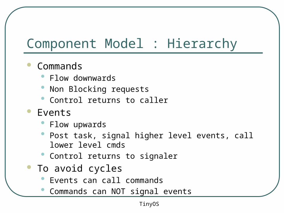
Component Model : Hierarchy
TinyOS 97
Commands• Flow downwards• Non Blocking requests• Control returns to caller
Events• Flow upwards• Post task, signal higher level events, call lower level cmds• Control returns to signaler
To avoid cycles• Events can call commands• Commands can NOT signal events