
Introduction to Electrical for Pneumatic Systems
42
1-1 Unit 1 Introduction to Electrical Control of Pneumatic Systems UNIT OBJECTIVE When you have completed this unit, you will be able to identify the Pneumatics II Training System components, and to safely operate the trainer. DISCUSSION OF FUNDAMENTALS In a pneumatic system, fluid power provides the muscles or power to do the work, while the control part provides the brain to command system operation. Control of a pneumatic system may range from the simple starting and stopping of the system to control extension and retraction of several cylinders in a completely automated factory. A pneumatic system can be controlled either manually or automatically. In manual control, system operation is sequenced and commanded by an operator who decides each action to take. In automatic control, system operation is sequenced and commanded by a controller that decides each action to take. Automatic control can be accomplished by means of: electrical signals (electrical control); compressed air (pneumatic control); mechanical link (mechanical control). Manual control is used in pneumatic systems performing operations that are not repetitive. An earthmoving truck such as those used in construction, farming, and mining is a common example of a machine requiring manual control. Since the operator must constantly change the position where the shovel digs and the depth at which it digs, automatic control could not be used because the sequence of operations is not repetitive. In systems requiring the repetition of a series of operations, however, it would be inefficient to manually shift the pneumatic valves each time the direction of air flow needs to be changed. As an example, Figures 1-1 and 1-2 show the manual and automatic operation of a pneumatic drilling system.
Transcript of Introduction to Electrical for Pneumatic Systems
1-1
������
������������������������� ��������������������������
UNIT OBJECTIVE
When you have completed this unit, you will be able to identify the Pneumatics IITraining System components, and to safely operate the trainer.
DISCUSSION OF FUNDAMENTALS
In a pneumatic system, fluid power provides the muscles or power to do the work,while the control part provides the brain to command system operation. Control ofa pneumatic system may range from the simple starting and stopping of the systemto control extension and retraction of several cylinders in a completely automatedfactory.
A pneumatic system can be controlled either manually or automatically.
In manual control, system operation is sequenced and commanded by an operatorwho decides each action to take.
In automatic control, system operation is sequenced and commanded by acontroller that decides each action to take. Automatic control can be accomplishedby means of:
� electrical signals (electrical control);� compressed air (pneumatic control);� mechanical link (mechanical control).
Manual control is used in pneumatic systems performing operations that are notrepetitive. An earthmoving truck such as those used in construction, farming, andmining is a common example of a machine requiring manual control. Since theoperator must constantly change the position where the shovel digs and the depthat which it digs, automatic control could not be used because the sequence ofoperations is not repetitive.
In systems requiring the repetition of a series of operations, however, it would beinefficient to manually shift the pneumatic valves each time the direction of air flowneeds to be changed.
As an example, Figures 1-1 and 1-2 show the manual and automatic operation ofa pneumatic drilling system.
������������������������������������������������ ���
1-2
MANUALLY-OPERATEDDIRECTIONAL CONTROL VALVE
DRILLCYLINDER
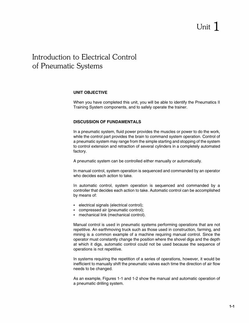
In Figure 1-1, the workpiece to drill is positioned manually on the drilling machine.A directional valve is then shifted manually to extend the drill cylinder. When theworkpiece is drilled, the directional valve is shifted in the opposite direction to retractthe drill cylinder. The drilled workpiece is then removed and replaced by a new one.Each step of the drilling sequence must be initiated by the operator, based on visualobservation.
Figure 1-1. Manual Control of a Pneumatic Drilling System.
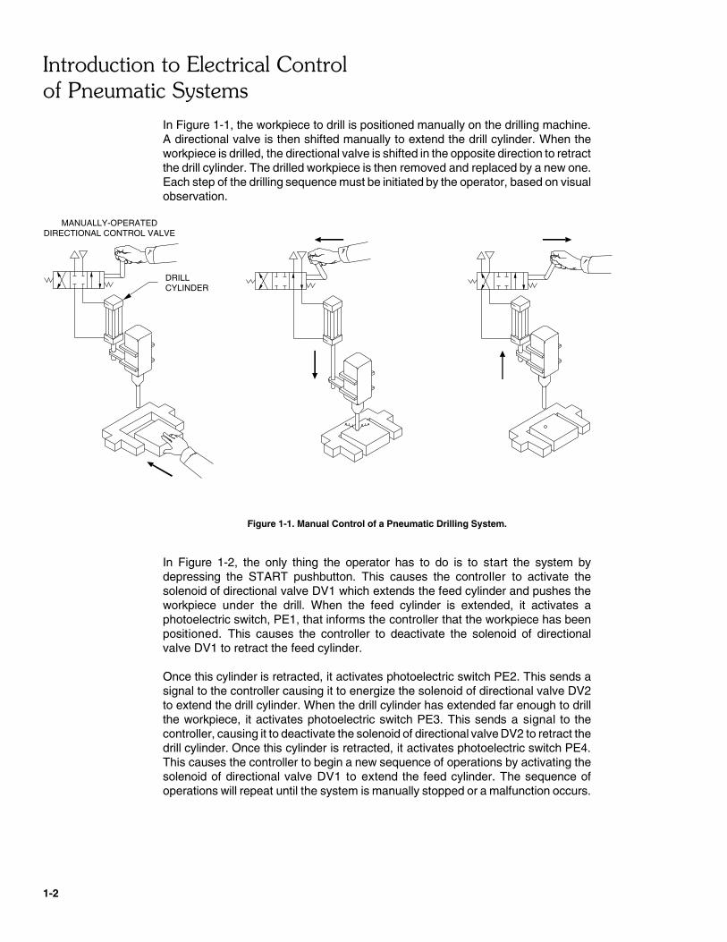
In Figure 1-2, the only thing the operator has to do is to start the system bydepressing the START pushbutton. This causes the controller to activate thesolenoid of directional valve DV1 which extends the feed cylinder and pushes theworkpiece under the drill. When the feed cylinder is extended, it activates aphotoelectric switch, PE1, that informs the controller that the workpiece has beenpositioned. This causes the controller to deactivate the solenoid of directionalvalve DV1 to retract the feed cylinder.
Once this cylinder is retracted, it activates photoelectric switch PE2. This sends asignal to the controller causing it to energize the solenoid of directional valve DV2to extend the drill cylinder. When the drill cylinder has extended far enough to drillthe workpiece, it activates photoelectric switch PE3. This sends a signal to thecontroller, causing it to deactivate the solenoid of directional valve DV2 to retract thedrill cylinder. Once this cylinder is retracted, it activates photoelectric switch PE4.This causes the controller to begin a new sequence of operations by activating thesolenoid of directional valve DV1 to extend the feed cylinder. The sequence ofoperations will repeat until the system is manually stopped or a malfunction occurs.
������������������������������������������������ ���
1-3
PE3
PE4
PE1
PE2
STOP
START
DIRECTIONAL VALVE DV2
SOLENOID
FEED CYLINDER
DRILL CYLINDER
DIRECTIONALVALVE DV1
COMPRESSEDAIRSUPPLY
SUPPLYAIRCOMPRESSED
CONTROLLER
SOLENOID
Figure 1-2. Automatic Control of a Pneumatic Drilling System.
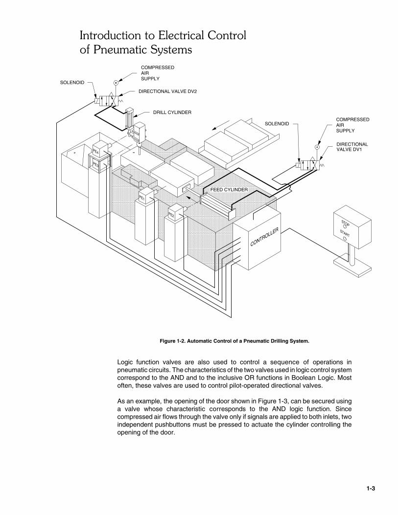
Logic function valves are also used to control a sequence of operations inpneumatic circuits. The characteristics of the two valves used in logic control systemcorrespond to the AND and to the inclusive OR functions in Boolean Logic. Mostoften, these valves are used to control pilot-operated directional valves.
As an example, the opening of the door shown in Figure 1-3, can be secured usinga valve whose characteristic corresponds to the AND logic function. Sincecompressed air flows through the valve only if signals are applied to both inlets, twoindependent pushbuttons must be pressed to actuate the cylinder controlling theopening of the door.
������������������������������������������������ ���
1-4
ANDFUNCTION
VALVE
DOORCYLINDER CYLINDER
Figure 1-3. Door Opening Control Using a Logic Function Valve.

1-5
INPUTELEMENT ELEMENT MECHANISM
ACTUATING FLUID POWERTO THEACTUATOR
INPUT SIGNALELECTRICAL
CONTROL SIGNALELECTRICAL
RELAYSPROGRAMMABLE
CONTROLLERPUSHBUTTONLIMIT
SWITCHSOLENOID-OPERATED
VALVE
CONTROLLER
������������
������������������������� ��!����
EXERCISE OBJECTIVE
� To identify the components of the Lab-Volt Pneumatics II Training System;� To describe the function of each of the following parts of an electrical control
circuit: input element, controller element and actuating mechanism.
DISCUSSION
Basic Principles of Electrical Control
Electrical control is by far the most popular type of automatic control used forindustrial pneumatic applications. As Figure 1-4 shows, an electrical control circuitconsists of an input element, a controller element and an actuating mechanism.
Figure 1-4. Electrical Control Circuit.
The input element provides an electrical signal to indicate that an actuator (cylinderor motor) has reached a specific position, or that it is time to start a sequence ofoperations. Examples of input elements are limit switches, pushbutton switches andrelay contacts. The signal issued from an input element is called "input signal"because it is sent to the input of a controller.
The controller element decides which action to take based on the signal receivedfrom the input element. The controller may be a set of electromechanical relays, aprogrammable logic controller (PLC), a logic function pneumatic valve or acomputer. The signal issued from the controller is called "control signal" becauseit is used to control the motion of an actuator through an actuating mechanism.

��������� ���������!��!���"��#����
1-6
The actuating mechanism provides air flow to a pneumatic actuator according to thecontrol signals received from the controller. Examples of actuating mechanisms aresolenoid-operated directional valves and pilot-operated directional valves.
Indicating devices such as pilot lamps and meters are not a part of the control circuitbecause they have no effect on the control process.
Electrical control offers high flexibility since the operation of a system can bechanged just by modifying the logic of the controller instead of modifying thepneumatic circuitry itself.
This course will show you how to control pneumatic circuits using electrical controlcomponents and logic function valves.
Procedure Summary
In this exercise, you will identify the components of the Lab-Volt Pneumatics IITraining System. You will then classify these components as input element,controller element, actuating mechanism and logic function valves.
EQUIPMENT REQUIRED
Refer to the Equipment Utilization Chart, in Appendix A of this manual, to obtain thelist of equipment required to perform this exercise.
PROCEDURE
Identifying the Trainer Components
� 1. Figure 1-5 shows the electropneumatic components of your trainer.Remove the components from their storage location. Identify eachcomponent by writing its part number in Figure 1-5.
� 2. Examine the DC Power Supply. It converts the 120-V ac line voltage intoa 24-V dc voltage to power the electrical components. The DC voltage issupplied through the red and black terminals located on top of the DCPower Supply.
Look at the information silkscreened next to the jacks. Which jackcorresponds to the positive (�) terminal? To the negative (�) terminal?

��������� ���������!��!���"��#����
1-7
DC POWER SUPPLY
P/N: P/N:
PUSHBUTTON STATION
P/N:
P/N:P/N:P/N:
P/N: P/N: P/N:
P/N:P/N:
LIMIT SWITCH ASSEMBLY
TIME-DELAY RELAY/COUNTER
DIRECTIONAL VALVESINGLE-SOLENOID OPERATED PRESSURE SWITCH
PHOTOELECTRIC SWITCHMAGNETIC PROXIMITY SWITCH
PILOT-LAMP STATIONRELAY
DIRECTIONAL VALVEDOUBLE-SOLENOID OPERATED
Figure 1-5. Electropneumatic Components of the Trainer.
��������� ���������!��!���"��#����
1-8
PUSHBUTTON CONTACTS
NORMALLY-OPEN NORMALLY-CLOSED
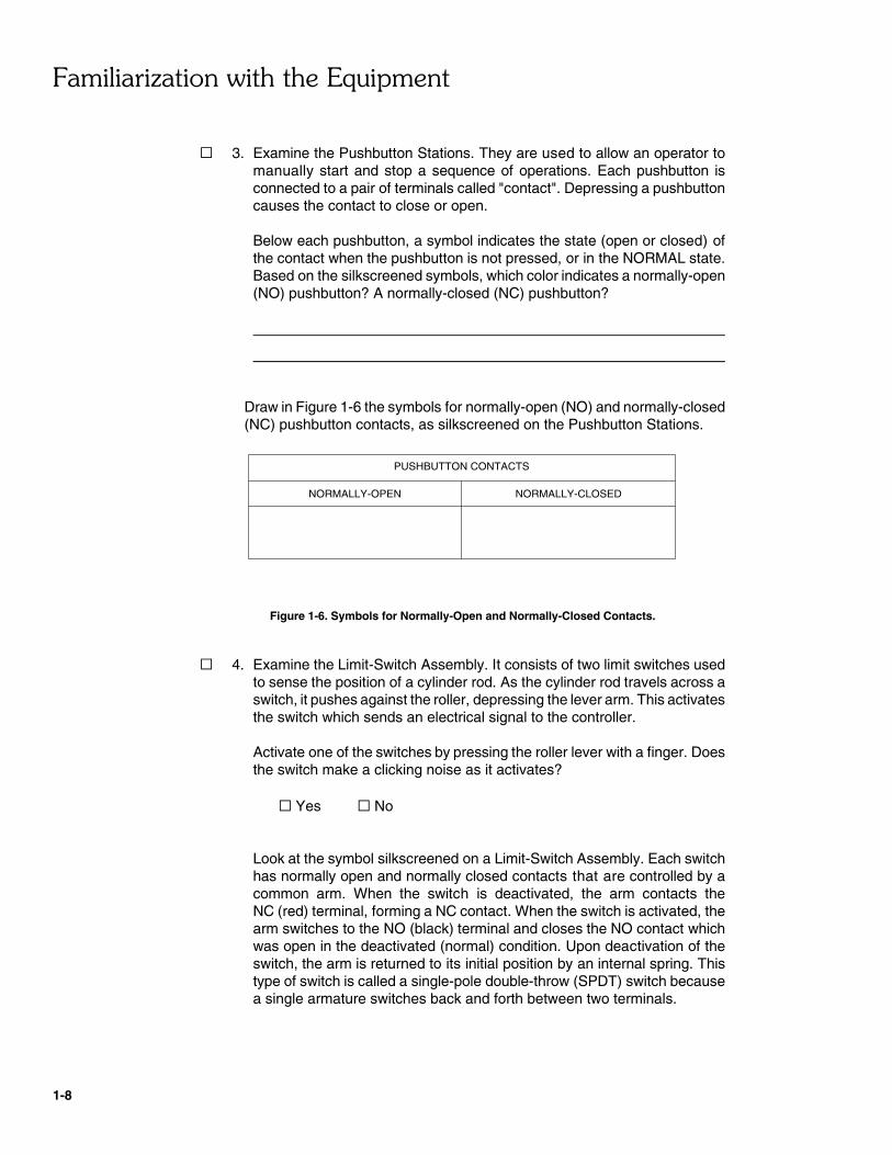
� 3. Examine the Pushbutton Stations. They are used to allow an operator tomanually start and stop a sequence of operations. Each pushbutton isconnected to a pair of terminals called "contact". Depressing a pushbuttoncauses the contact to close or open.
Below each pushbutton, a symbol indicates the state (open or closed) ofthe contact when the pushbutton is not pressed, or in the NORMAL state.Based on the silkscreened symbols, which color indicates a normally-open(NO) pushbutton? A normally-closed (NC) pushbutton?
Draw in Figure 1-6 the symbols for normally-open (NO) and normally-closed(NC) pushbutton contacts, as silkscreened on the Pushbutton Stations.
Figure 1-6. Symbols for Normally-Open and Normally-Closed Contacts.
� 4. Examine the Limit-Switch Assembly. It consists of two limit switches usedto sense the position of a cylinder rod. As the cylinder rod travels across aswitch, it pushes against the roller, depressing the lever arm. This activatesthe switch which sends an electrical signal to the controller.
Activate one of the switches by pressing the roller lever with a finger. Doesthe switch make a clicking noise as it activates?
� Yes � No
Look at the symbol silkscreened on a Limit-Switch Assembly. Each switchhas normally open and normally closed contacts that are controlled by acommon arm. When the switch is deactivated, the arm contacts theNC (red) terminal, forming a NC contact. When the switch is activated, thearm switches to the NO (black) terminal and closes the NO contact whichwas open in the deactivated (normal) condition. Upon deactivation of theswitch, the arm is returned to its initial position by an internal spring. Thistype of switch is called a single-pole double-throw (SPDT) switch becausea single armature switches back and forth between two terminals.

��������� ���������!��!���"��#����
1-9
Draw the symbol of the component in Figure 1-7. Identify the COMMON,NO, and NC terminals on your drawing.
Figure 1-7. Symbol for SPDT Limit Switch Contacts.
� 5. Examine the Magnetic Proximity Switches. They are used to sense theposition of a piston inside a cylinder. They are designed to clamp onto acylinder equipped with a special magnetic piston, as is the case of thecylinders supplied with your trainer. When a magnetic piston comes withinproximity of the switch, its magnetic field activates the switch, which sendsan electrical signal to the controller.
The (�) and (�) terminals on top of the switch are used to power thesensing cell. The three other terminals provide access to the NO andNC contacts. The Magnetic Proximity Switches supplied with your trainerare of the SPDT type.
Draw the symbol of the component in Figure 1-8. Identify the COMMON,NO, and NC terminals on your drawing.
Mount a Magnetic Proximity Switch on one of the cylinders. To do so,loosen the set screw on the proximity switch until the clamp is looseenough to slip over the cylinder tie rod. Position the switch at the cap endor at the rod end of the cylinder. Then tighten the set screw until the clampis attached firmly to the cylinder tie rod. Can the proximity switch bepositioned to indicate any position of the piston stroke?
� Yes � No

��������� ���������!��!���"��#����
1-10
SYMBOL
SET SCREW
TIE ROD
PROXIMITYMAGNETIC
SWITCH
Figure 1-8. Symbol for SPDT Magnetic Proximity Switch Contacts.
� 6. Examine the Diffuse Reflective Photoelectric Switch. It is used to sense theposition of a cylinder rod. It consists of a light source, a receiver, and a pairof NO and NC contacts. When powered, the light source projects a beamof infrared light. When the cylinder rod enters the beam, light reflects off therod back to the receiver, causing the switch contacts to turn on.
The (�) and (�) terminals on top of the switch are used to power theinfrared light source. The three other terminals provide access to the NOand NC contacts. The Diffuse Reflective Photoelectric Switch supplied withyour trainer is of the SPDT type.
Draw the symbol of the component in Figure 1-9. Identify the COMMON,NO, and NC terminals on your drawing.
Figure 1-9. Symbol for SPDT Photoelectric Switch Contacts.

��������� ���������!��!���"��#����
1-11
� 7. Examine the Pressure Switch. It is used to sense the pressure in apneumatic circuit. It has a pneumatic port which connects to a pneumaticcircuit like a pressure gage. When the circuit pressure reaches a presetlevel, the Pressure Switch is activated, which sends an electrical signal tothe controller.
Look at the symbol silkscreened on top of the switch. The Pressure Switchsupplied with your trainer is of the SPDT type. Draw the symbol of thecomponent in Figure 1-10.
Figure 1-10. Symbol for SPDT Pressure Switch Contacts.
� 8. Examine the Pilot-Lamp Station. The pilot lamps indicate the condition(activated or deactivated) of an associated device. Each lamp is connectedto a pair of terminals allowing connection of that lamp into a circuit. Drawthe symbol of a pilot lamp in Figure 1-11.
Figure 1-11. Pilot Lamp Symbol.
� 9. Look at the symbols silkscreened on the Relay. The Relay consist of a coil,CR, controlling three pairs of NO and NC contacts. Coil CR is to beconnected to an input element such as a limit switch. The relay contactsare to be connected to actuating mechanisms such as valve solenoids, orto other relay coils to perform various logic functions.
When the input element applies a DC voltage across coil CR, the coilenergizes and shifts the relay contacts to their opposite state. The

��������� ���������!��!���"��#����
1-12
NO contacts go closed and the NC contacts go open. When the DC voltageis removed from coil CR, the relay contacts are returned to their normalstate by a spring.
Based on the silkscreened symbols, what type of relay contact (NO/NC) isconnected between the following pairs of terminals: 1-2, 4-5, and 7-8?Between the pairs: 2-3, 5-6, and 8-9?
� 10. Examine the symbols silkscreened on the Time-Delay Relay / Counter. Thisdevice can be programmed for either timing or counting functions byconfiguring the thumbwheel switches on top of the unit. The Time-DelayRelay / Counter basically consists of a solenoid coil, an internal timer, acontrol (count) terminal, a reset terminal and two pairs of NO and NCcontacts.
The contacts can be activated or deactivated after a preset time delay inthe time-delay function or after a preset count of input pulses in thecounting function.
� 11. Examine the Directional Valve, Single-Solenoid Operated. This valve is anactuating mechanism providing fluid flow to an actuator such as a cylinderor motor. It is operated by an electrical solenoid which is connected to acontroller output, usually a relay contact.
When the solenoid is energized, the valve spool is shifted, causing theactuator to move in one direction. When the solenoid is deenergized, aninternal spring returns the valve spool to the normal condition, causing theactuator to move in the other direction. Draw the symbol of the componentin Figure 1-12.
Figure 1-12. Symbol of the Directional Valve, Single-Solenoid Operated.

��������� ���������!��!���"��#����
1-13
� 12. Examine the Directional Valve, Double-Solenoid Operated. This valve isoperated by two separate solenoids that shift the spool. Each solenoid mustbe connected to a controller output, usually a relay contact. When neithersolenoid is energized, the spool is kept in the center position by centeringsprings. Draw the symbol of the component in Figure 1-13.
Figure 1-13. Symbol of the Directional Valve, Double-Solenoid Operated.
� 13. Examine the Connection Leads. These wires are used to carry electricalsignals from one component of the electrical control circuit to another. Theycan be connected to any terminals on the electrical components of yourtrainer. The Connection Leads are stackable.
Practice connecting and disconnecting the leads, and stack the lead endsas shown in Figure 1-14. Disconnect and store.
Figure 1-14. Connecting and Stacking Leads.
� 14. Based on what you have learned in this exercise, classify the electropne-umatic components of your trainer as input element, controller element, oractuating mechanism by checking the appropriate box in Table 1-1.

��������� ���������!��!���"��#����
1-14
COMPONENTINPUT
ELEMENTCONTROLLER
ELEMENTACTUATINGMECHANISM
Directional Valve, Double-Solenoid Operated
Time-Delay Relay / Counter
Limit-Switch Assembly
Magnetic Proximity Switch
Relay
Pressure Switch
Directional Valve, Single-SolenoidOperated
Diffuse Reflective PhotoelectricSwitch
Pushbutton Station
Table 1-1. Components Classification.
� 15. Examine the Quick Exhaust Valve. As its name indicates, the QuickExhaust Valve increases the exhaust capacity of pneumatic cylinders andother pneumatic devices. Draw the symbol of the component inFigure 1-15.
Figure 1-15. Symbol of a Quick Exhaust Valve.
� 16. Examine the Pressure Regulator. As learned in the Lab-Volt course,Pneumatics Fundamentals, it is used to limit and maintain a constantpressure in a circuit. Draw the symbol of the component in Figure 1-16.
��������� ���������!��!���"��#����
1-15
Figure 1-16. Symbol of a Pressure Regulator.
� 17. Examine the AND Function Valve. Compressed air flows through the valveonly if signals are applied to both inlets. The characteristics of this valvecorrespond to the AND function in Boolean logic. Draw the symbol of thecomponent in Figure 1-17.
Figure 1-17. Symbol of the AND Function Valve.
� 18. Examine the Shuttle Valve. The characteristics of this valve correspond tothe inclusive OR function in Boolean logic. Either one input or the other willprovide an output. Draw the symbol of the component in Figure 1-18.
Figure 1-18. Symbol of the Shuttle Valve.

��������� ���������!��!���"��#����
1-16
CONCLUSION
In this exercise, you were introduced to the components of the Lab-Volt PneumaticsII Training System. You classified the electrical components as input elements,controller elements, or actuating mechanisms.
REVIEW QUESTIONS
1. Name the three parts of an electrical control circuit.
2. What is the function of an input element?
3. Name the two components used as controller elements in the PneumaticsTrainer.
4. What is meant by "contact" when speaking of an input switch or a control relay?
5. What device provides the 24-V dc voltage required to power the electricalcomponents of the Pneumatics Trainer?

1-17
���������
1. Which one of the following is not a part of an electrical control circuit?
a. Input element;b. Controller;c. Meter;d. Actuating mechanism.
2. An input element is a device that
a. decides what action to take based on the signals sent to it from theactuating mechanisms.
b. decides what action to take based on the signals sent to it from thecontroller.
c. provides an electrical signal to indicate that a pneumatic actuator hasreached a specific position, or that it is time to start an operation.
d. provides compressed air flow to a pneumatic actuator according to thecontrol signals sent to it from the controller.
3. Which one of the following is not an input element?
a. Pressure switch;b. Pushbutton;c. Pilot lamp;d. Limit switch.
4. What type of controller element is used for electrical control of the Lab-VoltPneumatics Trainer?
a. Relays;b. Programmable logic controller (PLC);c. Computer;d. Multimeter.
5. Which part of an electrical control circuit provides compressed air flow to apneumatic actuator according to the control signals sent to it from thecontroller?
a. Input element;b. Actuating mechanism;c. Relay;d. Metering device.
6. Which one of the following is an actuating mechanism?
a. Single-solenoid operated directional valve;b. Double-solenoid operated directional valve;c. Flow control valve;d. Both a and b.
$������ ���������
1-18
7. Switch and relay contacts are symbolized
a. as normally open.b. as normally closed.c. in normal (deactivated) position.d. in activated position.
8. A normally-open (NO) switch contact is a contact that
a. opens when the switch is activated.b. closes when the switch is activated.c. opens when the switch is deactivated.d. Both b and c.
9. A normally-closed (NC) relay contact is a contact that
a. opens when the relay coil is activated.b. closes when the relay coil is deactivated.c. closes when the relay coil is activated.d. Both a and b.
10. Which one of the following converts the 120-V ac line voltage into a 24-V dcvoltage that is used to power the electrical components of the Lab-VoltPneumatics Trainer?
a. Limit-Switch Assembly;b. Relay;c. Connection Leads;d. DC Power Supply.

2-1
�����"
��������� ����!��
UNIT OBJECTIVE
When you have completed this unit, you will be able to measure the voltage,resistance, and current in an electrical circuit. You will be able to read and drawsimple ladder diagrams. You will also assemble and operate simple pneumaticsystems.
DISCUSSION OF FUNDAMENTALS
In order to understand how electrical control circuits work, it is important that youfirst become familiar with the three parameters associated with basic electricity:voltage, resistance, and current. Exercise 2-1 defines these parameters anddescribes the relationship between them. It also shows how to measure eachparameter in an electrical DC circuit.
Electrical control circuits are often represented by ladder diagrams. Ladderdiagrams use a different set of symbols and rules than pneumatic schematics, buttheir function is the same: to show how components are connected and how thecircuit operates. Exercise 2-2 explains how a ladder diagram works, and how itrelates to the pneumatic circuitry. It also lists the rules for drawing ladder diagrams.
Exercise 2-3 introduces you to a basic electrically controlled pneumatic systemcalled a one-cycle reciprocation system. One-cycle reciprocation systems extendand retract a cylinder one time after an operator presses a START pushbutton.They are often used on machines where an operator must position the workpieceby hand before actuating the work cylinder.
Exercise 2-4 introduces you to the AND and OR logic function valves. These valvesare used to make decisions on the basis of rising or falling circuit pressures.

2-2
2-3
BATTERY
CURRENT FLOW
MAGNETIC FIELD
SOLENOID
+
−
���������"��
#���������������
EXERCISE OBJECTIVE
� To measure voltage, resistance, and current in an electrical control circuit;� To test the operation of an electrical control circuit;� To be aware of the safety rules to follow when using electrical equipment to
control a pneumatic system.
DISCUSSION
Fundamentals
Electricity is a form of energy used for lighting, heating, or providing control andpower for machines. It is produced by the flow of tiny particles of matter calledelectrons through a conducting material. Examples of conducting materials are iron,copper, and aluminum.
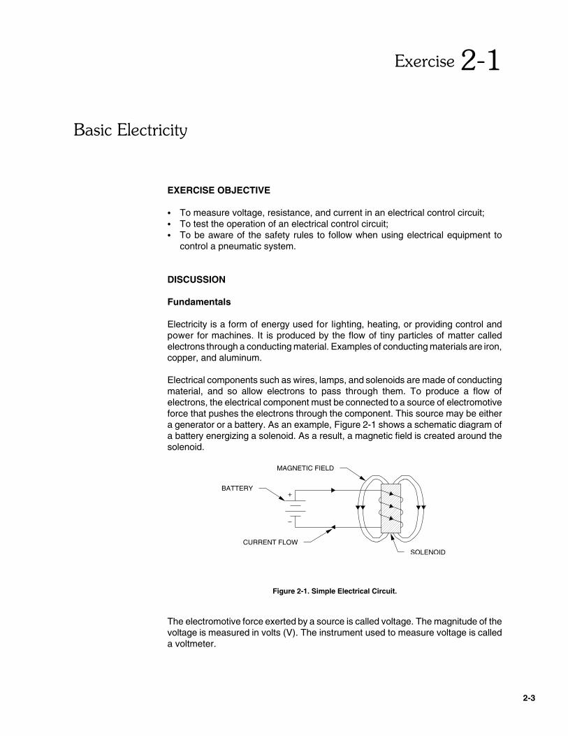
Electrical components such as wires, lamps, and solenoids are made of conductingmaterial, and so allow electrons to pass through them. To produce a flow ofelectrons, the electrical component must be connected to a source of electromotiveforce that pushes the electrons through the component. This source may be eithera generator or a battery. As an example, Figure 2-1 shows a schematic diagram ofa battery energizing a solenoid. As a result, a magnetic field is created around thesolenoid.
Figure 2-1. Simple Electrical Circuit.
The electromotive force exerted by a source is called voltage. The magnitude of thevoltage is measured in volts (V). The instrument used to measure voltage is calleda voltmeter.

%� ��������������
2-4
There is always an opposition to the flow of electrons through an electricalcomponent. This opposition is called resistance. Resistance is measured inohms (�). The instrument used to measure resistance is called an ohmmeter.
The result of electrons flowing through an electrical component is called current.The magnitude of the current is measured in amperes (A). The instrument used tomeasure current is called an ammeter.
Ohm’s law
The magnitude of the current flowing through an electrical component is equal to thevoltage drop across the component divided by the resistance of the component.This is called Ohm’s law. In equation form, it becomes:
� ��
�
where I is the current, in amperes (A)E is the voltage drop, in volts (V)R is the resistance, in ohms (�)
If, for example, the voltage drop across the solenoid in Figure 2-1 is 20 V and theresistance of the solenoid is 10 �, then the magnitude of the current flowing throughthe solenoid is 2 A.
Ohm’s law can be reformulated to calculate either voltage drop, resistance, orcurrent when the other two variables are known.
Electrical power
The capability of an electrical source to move electrons through a circuit is calledelectrical power. It is measured in watts (W). The amount of power generated by anelectrical source is equal to the voltage supplied by this source multiplied by thecurrent flowing through the circuit. In equation form, it becomes:
P = E × I
where P is the power, in watts (W)
Some of the electrical power generated by the source is dissipated as heat by eachcomponent in the circuit due to the resistance of the components. The rest of thepower is consumed by an electrical device called a load to perform useful work suchas producing light (lamp), providing rotary motion (motor), or moving a plunger(solenoid).
The amount of power consumed by a load is equal to the voltage drop across thisload multiplied by the current flowing through it. It is also equal to the square of the

%� ��������������
2-5
BATTERY
+
_
+
_
DC POWER SUPPLY
DIRECT-CURRENT (DC)SOURCE
ALTERNATING-CURRENT (AC)SOURCE
current flowing through the load multiplied by the resistance of the load. In equationform:
P = E × I= I2 × R
If, for example, the current flowing through the solenoid in Figure 2-1 is 2 A and theresistance of the solenoid is 5 �, then the power consumed by the solenoid is 20 W.
Types of Electric Current
Current flow through an electrical circuit may be one of two types: direct current oralternating current.
� Direct current (DC) is the type of current produced by batteries and DC powersupplies. This type of current flows in only one direction: from the positive (�)terminal of the battery or power supply towards the negative (�) terminal. Thepower supply supplied with your trainer is a DC power supply because itproduces a DC current.
Note: In DC circuits, the convention used for current flow says that currentflows from the positive (�) terminal of the DC source towards the negative(�) terminal, even though the electrons flow from the negative terminaltowards the positive terminal.
� Alternating current (AC) is the type of current supplied to most houses andplants. This type of current changes direction (polarity) many times each second.Examples of devices that produce AC current are alternators and AC generators.
Figure 2-2 shows the symbols used to represent DC and AC power sources inelectrical diagrams.
Figure 2-2. Symbols of DC and AC Power Sources.
%� ��������������
2-6
CLOSED CIRCUIT
SOLENOIDENERGIZED
+
_
+
_SUPPLY
PUSHBUTTON PRESSED,CONTACT CLOSED
_
+
OPEN CIRCUIT
SOLENOIDDEENERGIZED
PUSHBUTTON RELEASED,CONTACT OPEN
SUPPLYPOWERPOWER
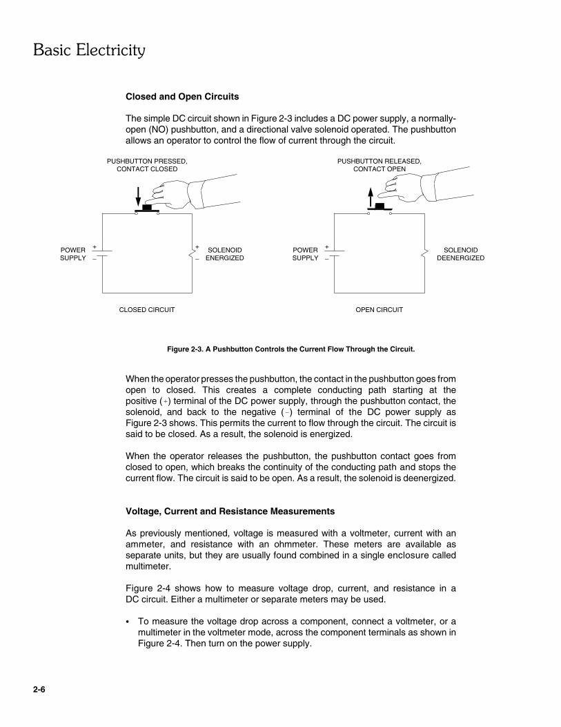
Closed and Open Circuits
The simple DC circuit shown in Figure 2-3 includes a DC power supply, a normally-open (NO) pushbutton, and a directional valve solenoid operated. The pushbuttonallows an operator to control the flow of current through the circuit.
Figure 2-3. A Pushbutton Controls the Current Flow Through the Circuit.
When the operator presses the pushbutton, the contact in the pushbutton goes fromopen to closed. This creates a complete conducting path starting at thepositive (�) terminal of the DC power supply, through the pushbutton contact, thesolenoid, and back to the negative (�) terminal of the DC power supply asFigure 2-3 shows. This permits the current to flow through the circuit. The circuit issaid to be closed. As a result, the solenoid is energized.
When the operator releases the pushbutton, the pushbutton contact goes fromclosed to open, which breaks the continuity of the conducting path and stops thecurrent flow. The circuit is said to be open. As a result, the solenoid is deenergized.
Voltage, Current and Resistance Measurements
As previously mentioned, voltage is measured with a voltmeter, current with anammeter, and resistance with an ohmmeter. These meters are available asseparate units, but they are usually found combined in a single enclosure calledmultimeter.
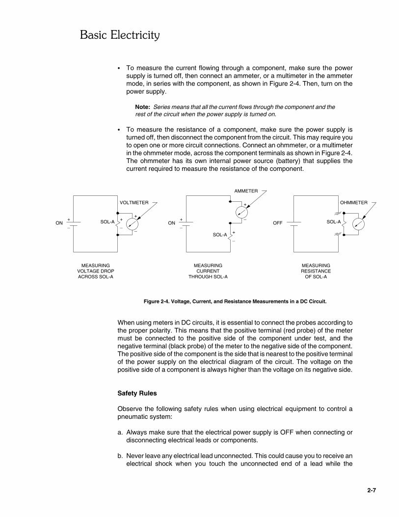
Figure 2-4 shows how to measure voltage drop, current, and resistance in aDC circuit. Either a multimeter or separate meters may be used.
� To measure the voltage drop across a component, connect a voltmeter, or amultimeter in the voltmeter mode, across the component terminals as shown inFigure 2-4. Then turn on the power supply.
%� ��������������
2-7
+
_
+
_SOL-A
_
+
ON
+
SOL-A
_
+
_
+
_ON OFF SOL-A
VOLTMETER
AMMETER
OHMMETER
MEASURINGVOLTAGE DROPACROSS SOL-A
MEASURINGCURRENT
THROUGH SOL-A
MEASURINGRESISTANCE
OF SOL-A
� To measure the current flowing through a component, make sure the powersupply is turned off, then connect an ammeter, or a multimeter in the ammetermode, in series with the component, as shown in Figure 2-4. Then, turn on thepower supply.
Note: Series means that all the current flows through the component and therest of the circuit when the power supply is turned on.
� To measure the resistance of a component, make sure the power supply isturned off, then disconnect the component from the circuit. This may require youto open one or more circuit connections. Connect an ohmmeter, or a multimeterin the ohmmeter mode, across the component terminals as shown in Figure 2-4.The ohmmeter has its own internal power source (battery) that supplies thecurrent required to measure the resistance of the component.
Figure 2-4. Voltage, Current, and Resistance Measurements in a DC Circuit.
When using meters in DC circuits, it is essential to connect the probes according tothe proper polarity. This means that the positive terminal (red probe) of the metermust be connected to the positive side of the component under test, and thenegative terminal (black probe) of the meter to the negative side of the component.The positive side of the component is the side that is nearest to the positive terminalof the power supply on the electrical diagram of the circuit. The voltage on thepositive side of a component is always higher than the voltage on its negative side.
Safety Rules
Observe the following safety rules when using electrical equipment to control apneumatic system: a. Always make sure that the electrical power supply is OFF when connecting or
disconnecting electrical leads or components.
b. Never leave any electrical lead unconnected. This could cause you to receive anelectrical shock when you touch the unconnected end of a lead while the
%� ��������������
2-8
electrical power supply is on. This could also cause a short circuit to occur whenthe unconnected end of a lead touches a metal surface.
c. Make sure the power switch of the electrical power supply is set to the O positionbefore connecting the power supply line cord.
d. When connecting an electrical circuit, make sure the contact terminals are freeof dirt, oil, and water. Dirt and oil are insulators and do not allow a goodconnection to be made. Water is a conductor and might make a connectionwhere it is not wanted.
It is also a good idea to review the safety rules regarding manual control of apneumatic system. These rules are indicated in the DISCUSSION of Exercise 1-1in the Pneumatics Fundamentals manual.
Procedure Summary
In this exercise, you will measure voltage and current in an electrical circuit. You willuse the measured values to calculate the resistance and the power consumed bya pilot lamp.
EQUIPMENT REQUIRED
Refer to the Equipment Utilization Chart, in Appendix A of this manual, to obtain thelist of equipment required to perform this exercise.
PROCEDURE
Voltage Measurement
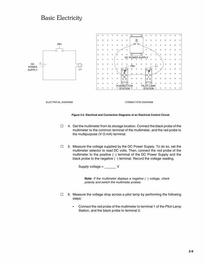
� 1. Connect the electrical control circuit shown in Figure 2-5.
� 2. Make sure the power switch on the DC Power Supply is set to theO position (OFF). Plug the line cord of the DC Power Supply into anAC outlet.
� 3. Turn on the DC Power Supply by setting its power switch to the I position.The red indicator lamp inside the power switch should light to indicate thata 24-V dc voltage is now supplied between the positive (�) and nega-tive (�) terminals of the power supply.
%� ��������������
2-9
ELECTRICAL DIAGRAM
POWERDC
SUPPLY
+
_
CONNECTION DIAGRAM
PILOT-LAMPSTATION
PUSHBUTTONSTATION
L1PB1
PB1
L1
+
DC POWER SUPPLY
Figure 2-5. Electrical and Connection Diagrams of an Electrical Control Circuit.
� 4. Get the multimeter from its storage location. Connect the black probe of themultimeter to the common terminal of the multimeter, and the red probe tothe multipurpose (V���mA) terminal.
� 5. Measure the voltage supplied by the DC Power Supply. To do so, set themultimeter selector to read DC volts. Then, connect the red probe of themultimeter to the positive (�) terminal of the DC Power Supply and theblack probe to the negative (�) terminal. Record the voltage reading.
Supply voltage = V
Note: If the multimeter displays a negative (�) voltage, checkpolarity and switch the multimeter probes.
� 6. Measure the voltage drop across a pilot lamp by performing the followingsteps:
� Connect the red probe of the multimeter to terminal 1 of the Pilot-LampStation, and the black probe to terminal 2.

%� ��������������
2-10
� Depress pushbutton PB1 to allow the current to flow through the circuitand observe the voltage reading on the multimeter. Record the valuein Table 2-1 under "VOLTAGE DROP (V)".
VOLTAGE DROP (V) CURRENT (A)
Table 2-1. Measurement Results.
� 7. Turn off the DC Power Supply by setting its power switch to the O positionand disconnect the multimeter probes from terminals 1 and 2 of the Pilot-Lamp Station.
Current Measurement
� 8. Measure the current flowing through the pilot lamp by performing thefollowing steps:
� Remove the electrical lead interconnecting terminal 2 of the pilot lampto the negative (�) terminal of the DC Power Supply.
� Set the multimeter to read a DC current. Then, connect the red probeof the multimeter to terminal 2 of the Pilot-Lamp Station and the blackprobe to the negative (�) terminal of the DC Power Supply.
� Turn on the DC Power Supply. Depress pushbutton PB1 to allow thecurrent to flow through the pilot lamp and observe the current readingin milliamperes (mA) on the multimeter. Record the value in Table 2-1under "CURRENT (A)".
� 9. Release pushbutton PB1. According to the current reading on themultimeter, does the current flow through the pilot lamp when thepushbutton is in the normal (released) position? Why?
� 10. Turn off the multimeter and the DC Power Supply.
Resistance Calculation
� 11. Based on the voltage drop and current recorded in Table 2-1, calculate theresistance of the pilot lamp using the Ohm’s law (R = E/I).
RPILOT LAMP =
%� ��������������
2-11
� 12. How will the current flow through the pilot lamp change if the voltage dropacross the pilot lamp is doubled and the pilot lamp resistance stays thesame?
� 13. Based on the voltage drop and current recorded in Table 2-1, calculate thepower consumed by the pilot lamp.
� 14. Based on the current recorded in Table 2-1 and the resistance calculatedin step 11, calculate the power consumed by the pilot lamp.
� 15. Compare the power value calculated in step 13 with that calculated instep 14. Are the values approximately equal?
� Yes � No
� 16. Disconnect and store all leads and components.
CONCLUSION
In this exercise, you learned how to measure voltage and current in an electricalcircuit.
You measured the voltage drop across a component by connecting a multimeter inthe voltmeter mode across the component terminals.
You measured the current flow through a component by connecting a multimeter inthe ammeter mode in series with the component.
You learned that when the voltage drop and current are known, Ohm’s law can beused to calculate the resistance.
You also learned how to calculate the power consumed by a load.

%� ��������������
2-12
REVIEW QUESTIONS
1. What is the difference between direct current (DC) and alternating current (AC)?
2. What are the units of measurement for voltage, resistance, current, and power?
3. What is the mathematical relationship between current, voltage drop, andresistance?
4. In a DC circuit, what is meant by the "positive (�) terminal" of a component?
5. Describe the method used to measure the current flowing through a component.
6. What are the two formulas for calculating the power consumed by an electricalcomponent?
%� ��������������
2-13
7. Can an ohmmeter or multimeter in ohmmeter mode be used to measure theresistance of an energized solenoid? Why?

2-14
2-15
ELECTRICAL DIAGRAM
POWERSUPPLY
+
_
PB1 L1
1
(+) (−)
LADDER DIAGRAM
(−)(+)
PB1 L1
POWER SUPPLY
���������"�"
$������%��&����
EXERCISE OBJECTIVE
� To explain how the ladder diagram relates to pneumatic circuitry;� To assemble and operate basic ladder diagrams;� To learn the rules for drawing ladder diagrams;� To describe the operation of an electromechanical control relay.
DISCUSSION
The electrical control circuits you have seen until now were represented by pictorial-type schematic diagrams. There are other methods of drawing schematic diagrams,and "ladder diagrams" is the most popular method.
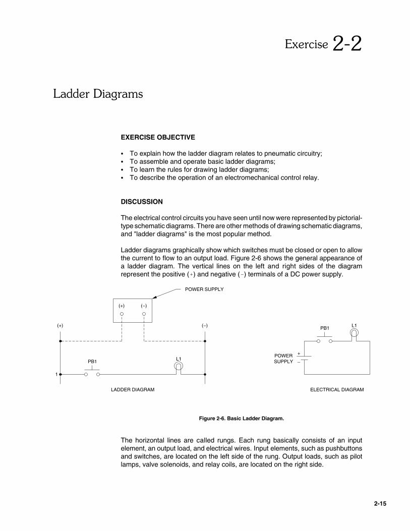
Ladder diagrams graphically show which switches must be closed or open to allowthe current to flow to an output load. Figure 2-6 shows the general appearance ofa ladder diagram. The vertical lines on the left and right sides of the diagramrepresent the positive (�) and negative (�) terminals of a DC power supply.
Figure 2-6. Basic Ladder Diagram.
The horizontal lines are called rungs. Each rung basically consists of an inputelement, an output load, and electrical wires. Input elements, such as pushbuttonsand switches, are located on the left side of the rung. Output loads, such as pilotlamps, valve solenoids, and relay coils, are located on the right side.
&����'�����
2-16
ELECTRICAL DIAGRAM
+
−
PB1 L1
1
(+) (−)
LADDER DIAGRAM
PB1 L1PB2
SERIES (AND) LOGIC
(+)
1
PB1
LADDER DIAGRAM
(−)
L1
ELECTRICAL DIAGRAM
−
+
PB1 L1
PARALLEL (OR) LOGIC
PB2
PB2
PB2
When the input element on a rung is closed, it forms a continuous path, or closedcircuit, to the output load, allowing the current to flow from the positive (�) terminalof the DC power supply to energize the output load. As an example, depressingpushbutton PB-1 in Figure 2-6 causes normally-open (NO) switch contact PB1 inrung 1 to close and pilot lamp L1 to turn on.
Ladder diagrams use graphic symbols which may differ from electrical symbols toillustrate the components. The ladder diagram graphic symbols of the electricalcomponents supplied with your trainer are shown in Appendix D.
Series and parallel logic
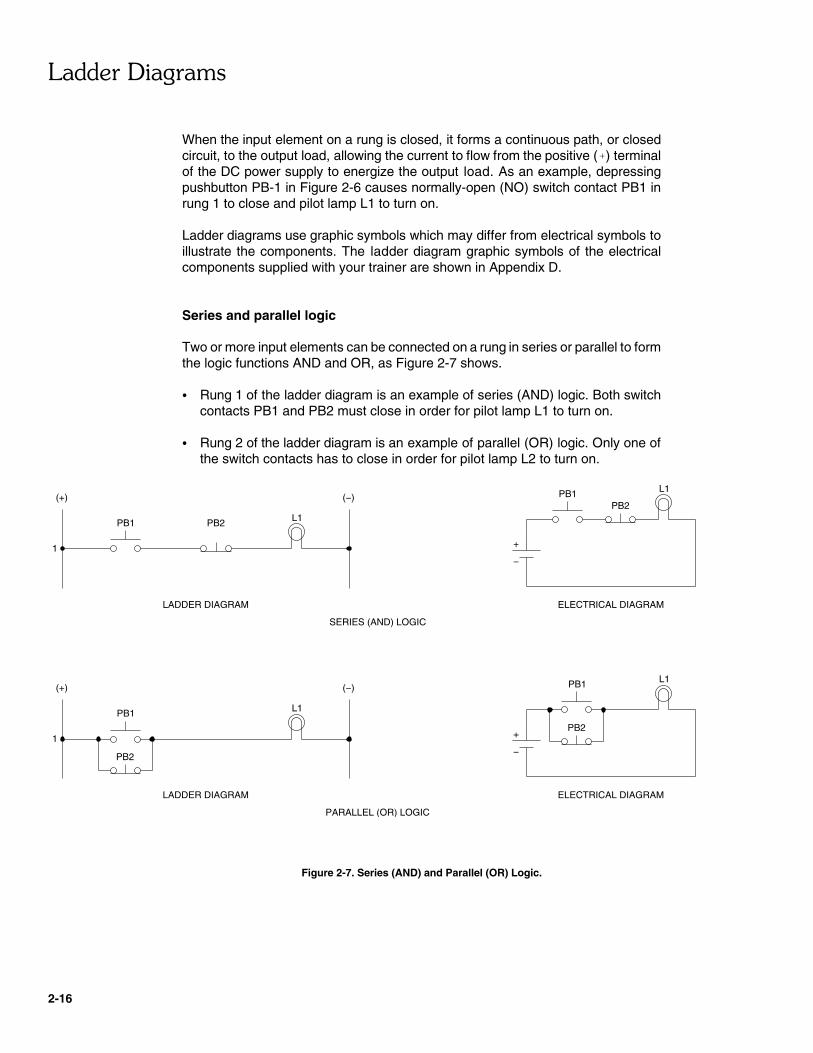
Two or more input elements can be connected on a rung in series or parallel to formthe logic functions AND and OR, as Figure 2-7 shows.
� Rung 1 of the ladder diagram is an example of series (AND) logic. Both switchcontacts PB1 and PB2 must close in order for pilot lamp L1 to turn on.
� Rung 2 of the ladder diagram is an example of parallel (OR) logic. Only one ofthe switch contacts has to close in order for pilot lamp L2 to turn on.
Figure 2-7. Series (AND) and Parallel (OR) Logic.
&����'�����
2-17
Rules for Drawing Ladder Diagrams
� The ladder diagram must show only electrical control devices, such as switches,relay coils, and solenoids. Pneumatic devices never appear on a ladder diagram,they are drawn on a pneumatic diagram.
� Input elements must be drawn on the left side of the ladder diagram, and outputloads must be drawn on the right side. There must be at least one input elementand one output load per rung. Input elements should never be connected directlyto the negative (�) terminal and load devices should never be connected directlyto the positive (�) terminal of the DC power supply.
When there are two or more output loads on a same rung, they must beconnected in parallel. Loads must never be connected in series on the samerung.
� All ladder rungs must be numbered and each device must be identified with arepresentative abbreviation. For example, PB is an abbreviation for pushbutton,and CR is an abbreviation for relay coil.
Contacts operated by a relay coil must be identified with the same abbreviationas the coil which operates them. For example, contacts operated by relaycoil CR1 are labeled CR1-A, CR1-B, CR1-C, etc.
Electromechanical Control Relays
Electromechanical control relays are used to perform complex logic functions. Asshown in Figure 2-8, they consist of a relay coil, a magnetic core, an armature, andone or more sets of normally-open (NO) and normally-closed (NC) contacts. Whencurrent flows through the relay coil, the magnetic core and armature attract eachother, causing the armature to move towards the core. This switches the relaycontacts to the activated state. The NO contacts go closed, while NC contacts goopen. When the current is removed from the relay coil, the armature is moved backto its original position by a spring, which returns the relay contacts to their normalstate.

&����'�����
2-18
NO CONTACT
CR
3PDT CONTACTS ELECTRICAL DIAGRAM SYMBOLS
RELAY COIL
NC CONTACT
THE DASHED LINEINDICATES THAT THE3 CONDUCTINGPARTS AREOPERATED BYTHE SAMEARMATURE
SPRING
RELAY CONTACT
RELAY COIL
MAGNETIC CORE
OPERATION
ARMATURE
NC
NO
COM
COM
NO
NC
NO
NC
COM
Figure 2-8. Triple-Pole, Double-Throw Control Relays.
The Relay supplied with your trainer consists of a relay coil and three sets of NOand NC contacts. The Relay is of the triple-pole, double-throw (3PDT) type,because it simultaneously switches three conducting parts back and forth betweentwo positions.
Procedure Summary
In the first part of the exercise, you will test a basic ladder diagram.
In the second part of the exercise, you will test ladder diagrams using series (AND)and parallel (OR) logic.
In the third part of the exercise, you will test a ladder diagram usingelectromechanical control relays.
&����'�����
2-19
CONNECTION DIAGRAM
PILOT-LAMPSTATION
PUSHBUTTONSTATION
L1PB1
+
DC POWER SUPPLY
(+)
1
PB1
LADDER DIAGRAM
(−)
L1
PB2
L2
PB2 L2
2
EQUIPMENT REQUIRED
Refer to the Equipment Utilization Chart, in Appendix A of this manual, to obtain thelist of equipment required to perform this exercise.
PROCEDURE
Basic Ladder Diagram
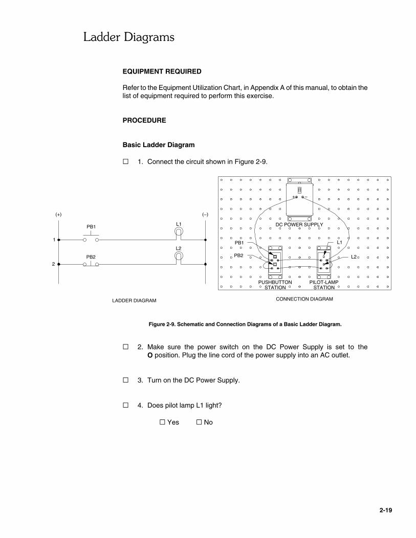
� 1. Connect the circuit shown in Figure 2-9.
Figure 2-9. Schematic and Connection Diagrams of a Basic Ladder Diagram.
� 2. Make sure the power switch on the DC Power Supply is set to theO position. Plug the line cord of the power supply into an AC outlet.
� 3. Turn on the DC Power Supply.
� 4. Does pilot lamp L1 light?
� Yes � No

&����'�����
2-20
CONNECTION DIAGRAM
PILOT-LAMPSTATION
PUSHBUTTONSTATION
+
DC POWER SUPPLY
(+)
1
PB1
LADDER DIAGRAM
(−)
L1PB2
PUSHBUTTONSTATION
PB2PB1 L1
� 5. Depress pushbutton PB1. What happens to pilot lamp L1? Explain theoperation by referring to the ladder diagram in Figure 2-9.
� 6. Does pilot lamp L2 light?
� Yes � No
� 7. Depress pushbutton PB2. What happens to pilot lamp L2? Explain theoperation by referring to the ladder diagram in Figure 2-9.
� 8. Turn off the DC Power Supply, and disconnect your circuit.
Ladder Diagrams Using Series (AND) and Parallel (OR) Logic
� 9. Connect the series logic circuit shown in Figure 2-10.
Figure 2-10. Testing a Ladder Diagram Using Series (AND) Logic.
&����'�����
2-21
� 10. Turn on the DC Power Supply.
� 11. Depress pushbutton PB1. Does pilot lamp L1 turn on?
� Yes � No
� 12. Depress pushbutton PB2. Does pilot lamp L1 turn on?
� Yes � No
� 13. Depress both pushbuttons PB1 and PB2. Does pilot lamp L1 turn on?Explain the operation by referring to the ladder diagram in Figure 2-10.
� 14. In a ladder rung containing two switch contacts in series, what is thecondition required for the output load to energize?
� 15. Turn off the DC Power Supply, then connect the parallel circuit shown inFigure 2-11.
� 16. Turn on the DC Power Supply. Depress pushbutton PB1. Does pilotlamp L1 turn on?
� Yes � No
� 17. Depress pushbutton PB2. Does pilot lamp L1 turn on?
� Yes � No
� 18. In a ladder rung containing two switch contacts in parallel, what is thecondition required for the output load to energize?
&����'�����
2-22
CONNECTION DIAGRAM
PILOT-LAMPSTATION
PUSHBUTTONSTATION
+
DC POWER SUPPLY
(+)
1
PB1
LADDER DIAGRAM
(−)
L1
PUSHBUTTONSTATION
PB2
PB2
PB1 L1
CONNECTION DIAGRAM
PILOT-LAMPSTATION
PUSHBUTTONSTATION
+
DC POWER SUPPLY
LADDER DIAGRAM
PB1 L1
(+)
2
PB1
(−)
L1
L2
1
3
CR1-B
CR1
CR1-A
RELAY
L2
CR1
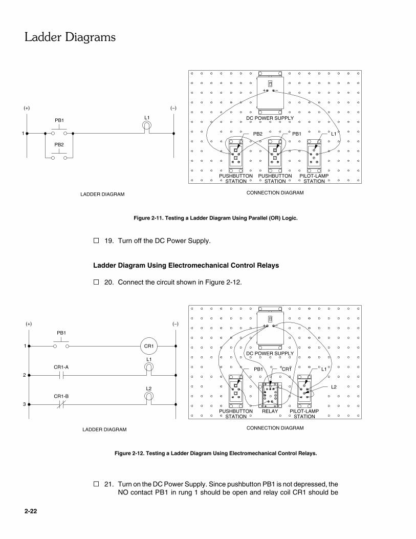
Figure 2-11. Testing a Ladder Diagram Using Parallel (OR) Logic.
� 19. Turn off the DC Power Supply.
Ladder Diagram Using Electromechanical Control Relays
� 20. Connect the circuit shown in Figure 2-12.
Figure 2-12. Testing a Ladder Diagram Using Electromechanical Control Relays.
� 21. Turn on the DC Power Supply. Since pushbutton PB1 is not depressed, theNO contact PB1 in rung 1 should be open and relay coil CR1 should be

&����'�����
2-23
deenergized. Therefore, NC relay contact CR1-B in rung 3 should beclosed and pilot lamp L2 should be on. Is pilot lamp L2 now on?
� Yes � No
� 22. Depress pushbutton PB1. What happens to pilot lamps L1 and L2? Explainthe operation by referring to the ladder diagram in Figure 2-12.
� 23. Release pushbutton PB1. What happens to the pilot lamps? Explain?
� 24. From your observations, can a relay provide more than one contact,allowing one relay to control more than one electrical component?
� Yes � No
� 25. Turn off the DC Power Supply by setting its power switch to the O position.
� 26. Disconnect and store all leads and components.
CONCLUSION
In the first part of the exercise, you tested the operation of a basic ladder diagram.You learned that a complete conducting path (closed circuit) must occur on a rungin order for the output load on this rung to energize. You saw that an NO contactkeeps the circuit open until closed, and that an NC contact keeps the circuit closeduntil open.
In the second part of the exercise, you tested the operation of ladder diagramsusing series (AND) and parallel (OR) logic. In a ladder diagram using several inputswitches in series, all switch contacts must close in order for the output load toenergize. In a ladder diagram using several input switches in parallel, only one ofthe switch contacts has to close in order for the output load to energize.
In the third part of the exercise, you tested the operation of a ladder diagram usingelectromechanical control relays. You learned that when a relay coil is energized,the relay contacts shift to their opposite position. Normally-open (NO) relay contacts

&����'�����
2-24
go closed and normally-closed (NC) contacts go open. When the relay coil isdeenergized, the relay contacts revert to their normal position.
REVIEW QUESTIONS
1. What do the vertical lines on the left and right sides of a ladder diagramrepresent?
2. Where should input switches and relay contacts be drawn on a ladder diagram?
3. Where should relay coils and valve solenoids be drawn on a ladder diagram?
4. Should a solenoid-operated directional valve appear in a ladder diagram or ina pneumatic diagram?
5. Should the solenoid of a solenoid-operated directional valve appear in a ladderdiagram or a pneumatic diagram?


