
Introduction to Digital Communications System
83
Wireless Information Transmission System Lab. National Sun Yat-sen University Institute of Communications Engineering Introduction to Digital Communications System
Transcript of Introduction to Digital Communications System

Wireless Information Transmission System Lab.
National Sun Yat-sen UniversityInstitute of Communications Engineering
Introduction to Digital Communications System
2
Recommended BooksDigital Communications / Fourth Edition (textbook)-- John G. Proakis, McGraw HillCommunication Systems / 4th Edition-- Simon Haykin, John Wiley & Sons, Inc.Digital Communications – Fundamentals and Applications / 2nd Edition-- Bernard Sklar, Prentice HallPrinciples of Communications / Fifth Edition-- Rodger E. Ziemer and William H. Tranter, John Wiley & Sons, Inc.Modern Digital and Analog Communication Systems-- B.P. Lathi, Holt, Rinehart and Winston, Inc.

3
Example of Communications System
Switch
TransmissionEquipment
LocalLoop
regenerator
T1/E1 Facilities
Switch
TransmissionEquipment
LocalLoop
regenerator
T1/E1 Facilities MUX
SONETSDH
Public Switched Telephone Network (PSTN)
A/D Conversion(Digitization)
A/D Conversion(Digitization)
A/D Conversion(Digitization)
Central Office
Central Office
Central Office
T1/E1 Facilities
Switch
TransmissionEquipment
LocalLoop
regenerator
T1/E1 Facilities
MobileSwitching
Center
MobileSwitching
Center
BaseStation
BaseStation

4
Basic Digital Communication Nomenclature
Textual Message: information comprised of a sequence of characters.Binary Digit (Bit): the fundamental information unit for all digital systems.Symbol (mi where i=1,2,…M): for transmission of the bit stream; groups of k bits are combined to form new symbol from a finite set of M such symbols; M=2k.Digital Waveform: voltage or current waveform representing a digital symbol.Data Rate: Symbol transmission is associated with a symbol duration T. Data rate R=k/T [bps].Baud Rate: number of symbols transmitted per second [baud].

5
Nomenclature Examples

6
Messages, Characters, and Symbols

7
Typical Digital Communications System
Information Bits
)(ˆ tsi
Format SourceEncoding Encryption Channel
Encoding Multiplexing Modulation FrequencySpreading
MultipleAccess
TXRFPA
BitStream
DigitalWaveformSynchronization
CHANNEL
Source Bits Channel Bits
Channel BitsSource Bits
)(tsiDigitalInput
im
DigitalOutput
im̂
Information Sink
From Other Sources
To Other Destinations
Optional
Essential
Interleaving
Format SourceDecoding Decryption Channel
Decoding Demultiplexing Demodulation FrequencyDespreading
MultipleAccess
RXRFIF
Deinterleaving

Wireless Information Transmission System Lab.
National Sun Yat-sen UniversityInstitute of Communications Engineering
Format

9
Typical Digital Communications System
Information Bits
)(ˆ tsi
Format SourceEncoding Encryption Channel
Encoding Multiplexing Modulation FrequencySpreading
MultipleAccess
TXRFPA
BitStream
DigitalWaveformSynchronization
CHANNEL
Source Bits Channel Bits
Channel BitsSource Bits
)(tsiDigitalInput
im
DigitalOutput
im̂
Information Sink
From Other Sources
To Other Destinations
Optional
Essential
Interleaving
Format SourceDecoding Decryption Channel
Decoding Demultiplexing Demodulation FrequencyDespreading
MultipleAccess
RXRFIF
Deinterleaving
10
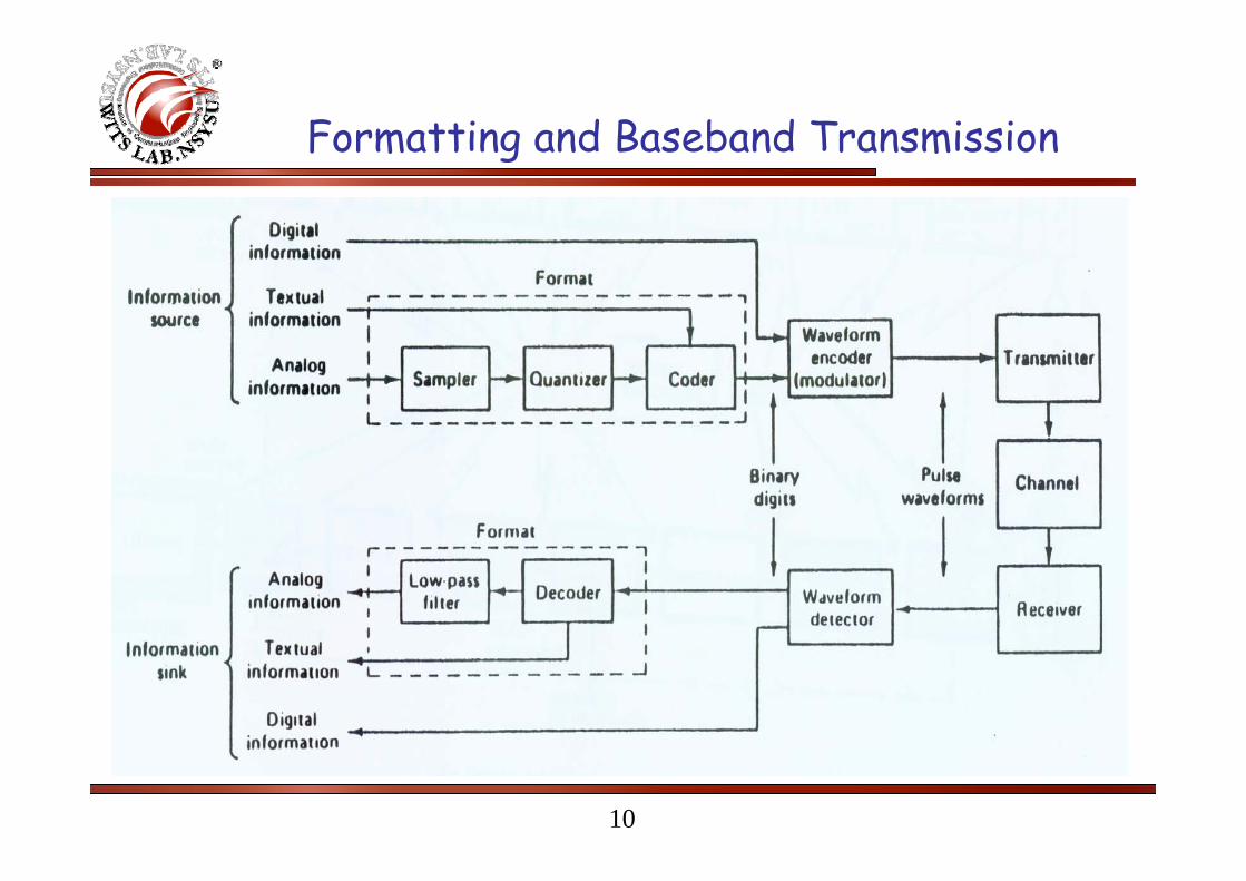
Formatting and Baseband Transmission

11
Sampling Theorem
12
Sampling Theorem
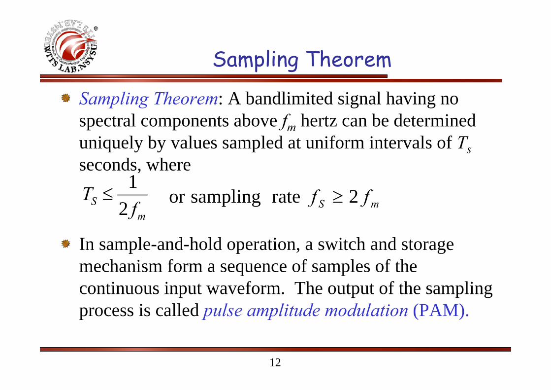
Sampling Theorem: A bandlimited signal having no spectral components above fm hertz can be determined uniquely by values sampled at uniform intervals of Tsseconds, where
In sample-and-hold operation, a switch and storage mechanism form a sequence of samples of the continuous input waveform. The output of the sampling process is called pulse amplitude modulation (PAM).
mS f
T21
≤mS ff 2 rate samplingor ≥

13
Sampling Theorem
∑∞
−∞=
−=∗=n
SS
S nffXT
fXfXfX )(1)()()( δ

14
Spectra for Various Sampling Rates

15
Natural Sampling
16
Pulse Code Modulation (PCM)
PCM is the name given to the class of baseband signals obtained from the quantized PAM signals by encoding each quantized sample into a digital word.
The source information is sampled and quantized to one of L levels; then each quantized sample is digitally encoded into an ℓ-bit (ℓ=log2L) codeword.

17
Example of Constructing PCM Sequence

18
Uniform and Non-uniform Quantization

19
Statistical Distribution of Single-Talker Speech Amplitudes
50% of the time, speech voltage is less than ¼ RMS.Only 15% of the time, voltage exceeds RMS.Typical voice signal dynamic range is 40 dB.

20
Problems with Linear Quantization
Fact: Unacceptable S/N for small signals.Solution:
Increasing quantization levels – price is too high.Applying nonlinear quantization – achieved by first distorting the original signal with a logarithmic compression characteristic and then using a uniform quantizer.
At the receiver, an inverse compression characteristic, called expansion, is applied so that the overall transmission is not distorted. The processing pair is referred to as companding.

21
Implementation of Non-linear Quantizer

22
Companding CharacteristicsIn North America: μ-law compression:
In Europe: A-law compression:⎩⎨⎧
<−≥+
=
⋅+
+=
0for 10for 1
sgn
where
sgn)1(log
)]/(1[log maxmax
xx
x
xxx
yye
e
μμ
⎪⎪⎩
⎪⎪⎨
⎧
≤<⋅+
+
≤<⋅+=
11 sgnlog1
)]/([log1
10 sgnlog1
)/(
max
maxmax
max
maxmax
xx
Ax
AxxA
y
Axx
xA
xxAy
y
e
e
e

23
Compression CharacteristicsStandard values of μ is 255 and A is 87.6.

Wireless Information Transmission System Lab.
National Sun Yat-sen UniversityInstitute of Communications Engineering
Source Coding

25
Typical Digital Communications System
Information Bits
)(ˆ tsi
Format SourceEncoding Encryption Channel
Encoding Multiplexing Modulation FrequencySpreading
MultipleAccess
TXRFPA
BitStream
DigitalWaveformSynchronization
CHANNEL
Source Bits Channel Bits
Channel BitsSource Bits
)(tsiDigitalInput
im
DigitalOutput
im̂
Information Sink
From Other Sources
To Other Destinations
Optional
Essential
Interleaving
Format SourceDecoding Decryption Channel
Decoding Demultiplexing Demodulation FrequencyDespreading
MultipleAccess
RXRFIF
Deinterleaving

26
Source Coding
Source coding deals with the task of forming efficient descriptions of information sources.For discrete sources, the ability to form reduced data rate descriptions is related to the information content and the statistical correlation among the source symbols.For analog sources, the ability to form reduced data rate descriptions, subject to a fixed fidelity criterion I related to the amplitude distribution and the temporal correlation of the source waveforms.

27
Huffman Coding
The Huffman code is source code whose average word length approaches the fundamental limit set by the entropy of a discrete memoryless source.
The Huffman code is optimum in the sense that no other uniquely decodable set of code-words has smaller average code-word length for a given discrete memoryless source.

28
Huffman Encoding Algorithm
1. The source symbols are listed in order of decreasing probability. The two source symbols of lowest probability are assigned a 0 and a 1.
2. These two source symbols are regarded as being combined into a new source symbol with probability equal to the sum of the two original probabilities. The probability of the new symbol is placed in the list in accordance with its value.
3. The procedure is repeated until we are left with a final list of source statistics of only two for which a 0 and a 1 are assigned.
4. The code for each (original) source symbol is found by working backward and tracing the sequence of 0s and 1s assigned to that symbol as well as its successors.

29
Example of Huffman CodingSymbol
S0S1S2S3S4
Probability0.40.20.20.10.1
Code Word001011010011
Symbol
S0S1S2S3S4
Stage 1
0.40.20.20.10.1
Stage 2
0.40.20.20.2
Stage 3
0.40.40.2
Stage 4
0.60.4
0
1
0
1
0
1
0
1

30
Properties of Huffman Code
Huffman encoding process is not unique.Code words for different Huffman encoding process can have different lengths. However, the average code-word length is the same.When a combined symbol is moved as high as possible, the resulting Huffman code has a significantly smaller variance than when it is moved as low as possible.Huffman code is a prefix code.
A prefix code is defined as a code in which no code-word is the prefix of any other code-word.

31
Bit Compression Technologies for Voice
Differential PCM (DPCM)Adaptive DPCM
Delta Modulation (DM)Adaptive DM (ADM)
Speech Encoding
.
.
.

32
Differential PCM (DPCM)

33
Delta Modulation (DM)
Delta modulation is a one-bit DPCM.Advantage: bit compression.Disadvantage: slope overload.

34
Speech Coding Objective
Reduce the number of bits needed to be transmitted, therefore lowering the bandwidth required.

35
Speech PropertiesVoiced Sound
Arises in generation of vowels and latter portion of some consonants.Displays long-term repetitive pattern corresponding to the duration of a pitch intervalPulse-like waveform.
Unvoiced SoundArises in pronunciation of certain consonants such as “s”, “f”, “p”, “j”, “x”, …, etc.Noise-like waveform.

36
Categories of Speech EncodingWaveform Encoding
Treats voice as analog signal and does not use properties of speech:
Source Model Coding or VocodingTreats properties of speech to preserve word information
Hybrid or parametric methodsCombines waveform and vocoding

37
Linear Predictive Coder (LPC)

38
Multi-Pulse Linear Predictive Coder(MP-LPC)

39
Regular Pulse Excited Long Term Prediction Coder (RPE-LPT)

40
Code-Excited Linear Predictive (CELP)

41
Speech Coder Complexity

42
Speech Processing for GSM
Composition of the 13 kbps signal:36 bits for filter parameters every 20 ms.9 bits for LTP every 5 ms.47 bits for RPE every 5 ms.
Thus, in a 20 ms (2080-bit block, or 260 sample) interval, we need a total of36+9*20/5+47*20/5=260 bits.Data Rate = 260/(20 ms) = 13 kbps.

43
Speech Processing for IS-54
Composition of the 7.95 kbps signal:43 bits for filter parameters every 20 ms.7 bits for LTP every 5 ms.88 bits for codebook every 20 ms.
Thus, in a 20 ms (2080-bit block, or 260 samples) interval, we need a total of:43+7*20/5+88=159 bits.Data Rate = 159/(20ms) = 7.95 kbps.
Wireless Information Transmission System Lab.
National Sun Yat-sen UniversityInstitute of Communications Engineering
Channel Coding

45
Typical Digital Communications System
Information Bits
)(ˆ tsi
Format SourceEncoding Encryption Channel
Encoding Multiplexing Modulation FrequencySpreading
MultipleAccess
TXRFPA
BitStream
DigitalWaveformSynchronization
CHANNEL
Source Bits Channel Bits
Channel BitsSource Bits
)(tsiDigitalInput
im
DigitalOutput
im̂
Information Sink
From Other Sources
To Other DestinationsOptional
Essential
Interleaving
Format SourceDecoding Decryption Channel
Decoding Demultiplexing Demodulation FrequencyDespreading
MultipleAccess
RXRFIF
Deinterleaving
46
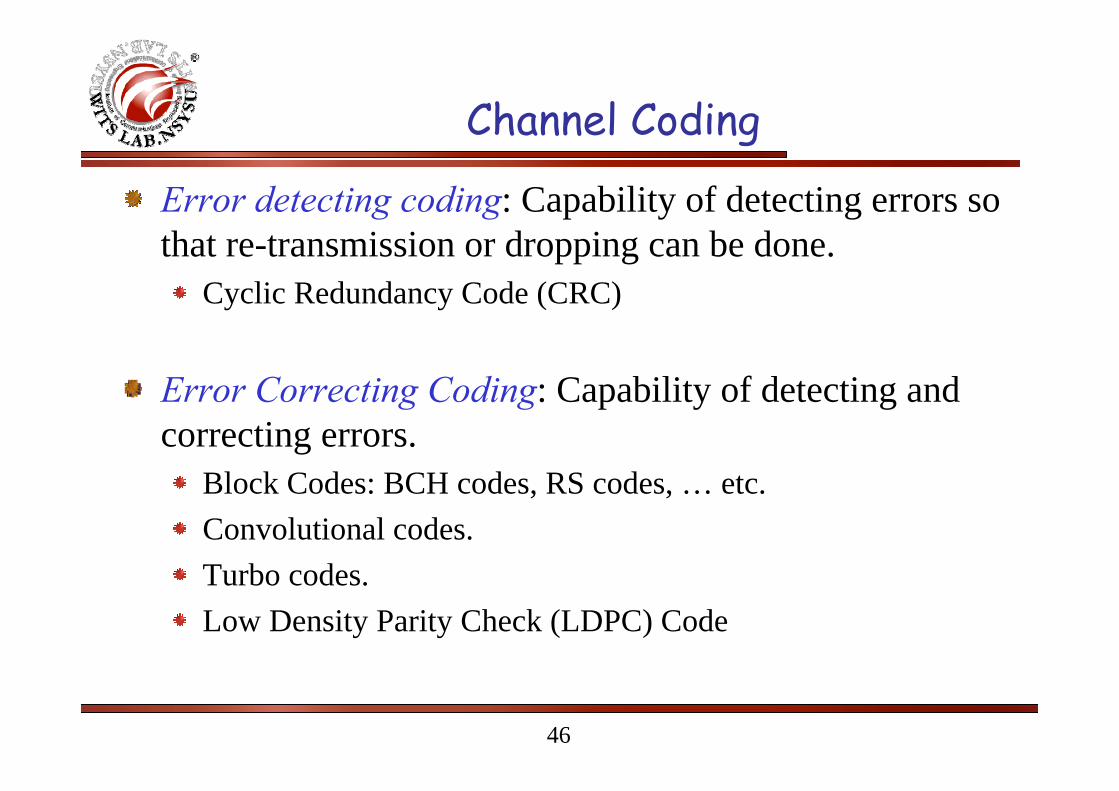
Channel Coding
Error detecting coding: Capability of detecting errors so that re-transmission or dropping can be done.
Cyclic Redundancy Code (CRC)
Error Correcting Coding: Capability of detecting and correcting errors.
Block Codes: BCH codes, RS codes, … etc.Convolutional codes.Turbo codes.Low Density Parity Check (LDPC) Code

47
CRC in WCDMA
gCRC24(D) = D 24 + D 23 + D 6 + D 5 + D + 1;
gCRC16(D) = D 16 + D 12 + D 5 + 1;
gCRC12(D) = D 12 + D 11 + D 3 + D 2 + D + 1;
gCRC8(D) = D 8 + D 7 + D 4 + D 3 + D + 1.
48
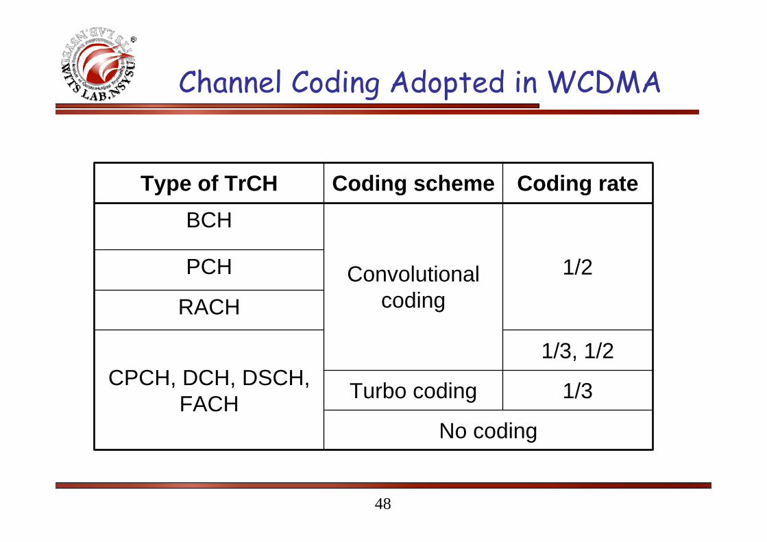
Channel Coding Adopted in WCDMA
No coding
1/3Turbo coding
1/3, 1/2CPCH, DCH, DSCH,
FACH
RACH
PCH 1/2Convolutionalcoding
BCH
Coding rateCoding schemeType of TrCH
49
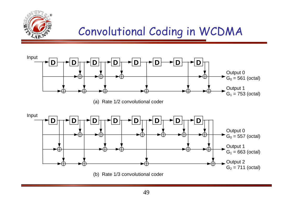
Convolutional Coding in WCDMA
Output 0G0 = 557 (octal)
InputD D D D D D D D
Output 1G1 = 663 (octal)
Output 2G2 = 711 (octal)
Output 0G0 = 561 (octal)
InputD D D D D D D D
Output 1G1 = 753 (octal)
(a) Rate 1/2 convolutional coder
(b) Rate 1/3 convolutional coder

50
Turbo Coder in WCDMA
xk
xk
zk
Turbo codeinternal interleaver
x’k
z’k
D
DDD
DD
Input
OutputInput
Output
x’k
1st constituent encoder
2nd constituent encoder

Wireless Information Transmission System Lab.
National Sun Yat-sen UniversityInstitute of Communications Engineering
Interleaving

52
Typical Digital Communications System
Information Bits
)(ˆ tsi
Format SourceEncoding Encryption Channel
Encoding Multiplexing Modulation FrequencySpreading
MultipleAccess
TXRFPA
BitStream
DigitalWaveformSynchronization
CHANNEL
Source Bits Channel Bits
Channel BitsSource Bits
)(tsiDigitalInput
im
DigitalOutput
im̂
Information Sink
From Other Sources
To Other Destinations
Optional
Essential
Interleaving
Format SourceDecoding Decryption Channel
Decoding Demultiplexing Demodulation FrequencyDespreading
MultipleAccess
RXRFIF
Deinterleaving

53
Bursty Error in Fading Channel

54
Interleaving Mechanism (1/2)
BitInterleaver
x y
y
j x n-bitShift registers
x
Write Clock Read Clock
Bit Stream before entering bit interleaver:x=(a11 a12 … a1n a21 a22 … a2n … aj1 aj2 … ajn)

55
Interleaving Mechanism (2/2)
Conceptually, the WRITE clock places the bit stream x by the row while the REA clock takes the bit stream y by the column:
Bit stream at the output of the bit interleaver:⎥⎥⎥⎥⎥⎥⎥⎥
⎦
⎤
⎢⎢⎢⎢⎢⎢⎢⎢
⎣
⎡
jnjj
n
n
aaa
aaaaaa
.....................
...
...
21
22221
11211
( )jnnnjj aaaaaaaaay ............ 212221212111=

56
Burst Error Protection with Interleaver
Wireless Information Transmission System Lab.
National Sun Yat-sen UniversityInstitute of Communications Engineering
Modulation

58
Typical Digital Communications System
Information Bits
)(ˆ tsi
Format SourceEncoding Encryption Channel
Encoding Multiplexing Modulation FrequencySpreading
MultipleAccess
TXRFPA
BitStream
DigitalWaveformSynchronization
CHANNEL
Source Bits Channel Bits
Channel BitsSource Bits
)(tsiDigitalInput
im
DigitalOutput
im̂
Information Sink
From Other Sources
To Other Destinations
Optional
Essential
Interleaving
Format SourceDecoding Decryption Channel
Decoding Demultiplexing Demodulation FrequencyDespreading
MultipleAccess
RXRFIF
Deinterleaving
59
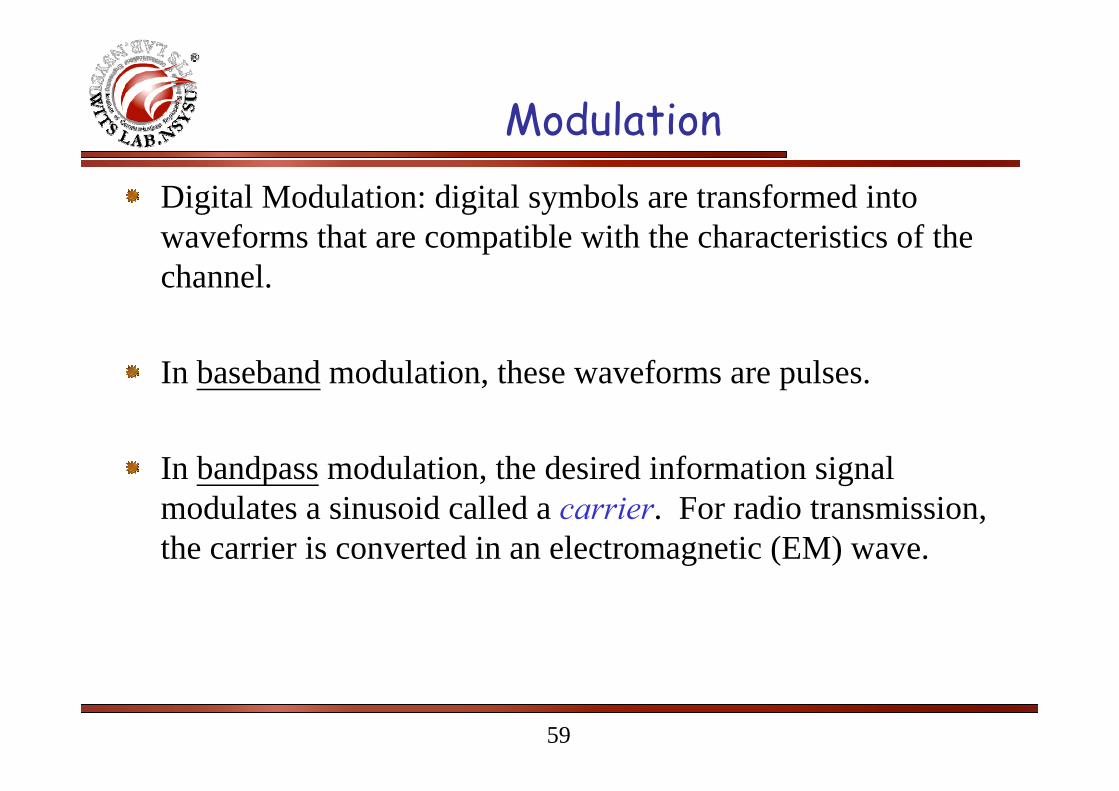
ModulationDigital Modulation: digital symbols are transformed into waveforms that are compatible with the characteristics of the channel.
In baseband modulation, these waveforms are pulses.
In bandpass modulation, the desired information signal modulates a sinusoid called a carrier. For radio transmission, the carrier is converted in an electromagnetic (EM) wave.

60
Digital Modulations
Basic digital modulated signal:
v(t) = A(t) cos (ωt + θ)
Where A(t) = Amplitude; ω = Frequency; θ = Phase;

61
Basic Digital Modulations

62
Extended Modulated Signals – M-FSKExample: 16-FSK
Every 4 bits is encoded as: 16,,2,1 )cos( …=⋅ jtA jω
Gray Coding.
63
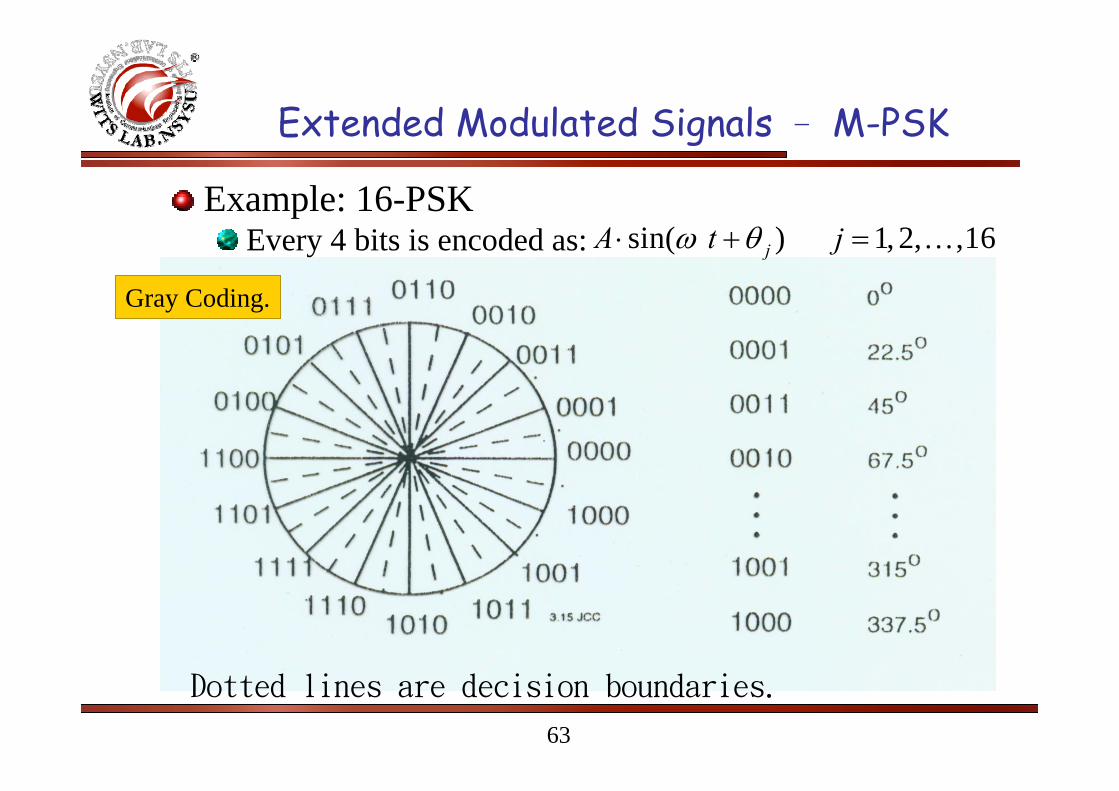
Extended Modulated Signals – M-PSK
Example: 16-PSKEvery 4 bits is encoded as: sin( ) 1, 2, ,16jA t jω θ⋅ + = …
Dotted lines are decision boundaries.
Gray Coding.
64
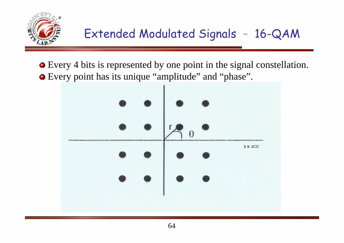
Extended Modulated Signals – 16-QAM
Every 4 bits is represented by one point in the signal constellation.Every point has its unique “amplitude” and “phase”.

65
Quadrature Phase Shift Keying (QPSK)

66
Spectrum of QPSK Signals
( ) ( )( )
( )( )
2 2sin sinc s c s
QPSK bc c
f f T f f TP f E
f f T f f Tπ π
π π
⎡ ⎤⎛ ⎞ ⎛ ⎞− − −⎢ ⎥= +⎜ ⎟ ⎜ ⎟⎜ ⎟ ⎜ ⎟− − −⎢ ⎥⎝ ⎠ ⎝ ⎠⎣ ⎦

67
Offset QPSK (OQPSK)For QPSK, the occasional phase shift of πradians can cause the signal envelope to pass through zero for just an instant.The amplification of the zero-crossings brings back the filtered sidelobes since the fidelity of the signal at small voltage levels is lost in transmission.To prevent the regeneration of sidelobes and spectral widening, it is imperative that QPSK signals that use pulse shaping be amplified only using linear amplifiers, which are less efficient.A modified form of QPSK, called offset QPSK (OQPSK) or staggered QPSK is less susceptible to these deleterious effects and supports more efficient amplification.OQPSK ensures there are fewer baseband signal transitions.Spectrum of an OQPSK signal is identical to that of QPSK.

68
Offset QPSK (OQPSK)The time offset waveforms that are applied to the in-phase and quadrature arms of an OQPSK modulator. Notice that a half-symbol offset is used.

69
π/4-DQPSK

70
Inter-Symbol Interference (ISI)

71
Inter Symbol Interference (ISI)
Inter-Symbol Interference (ISI) arises because of imperfections in the overall frequency response of the system. When a short pulse of duration Tb seconds is transmitted through a band-limited system, the frequency components constituting the input pulse are differentially attenuated and differentially delayed by the system. Consequently, the pulse appearing at the output of the system is dispersed over an interval longer than Tb seconds, thereby resulting in inter-symbol interference.Even in the absence of noise, imperfect filtering and system bandwidth constraints lead to ISI.
72
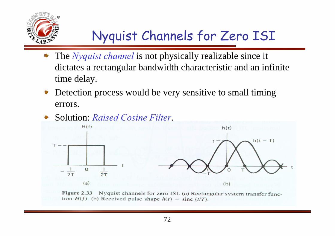
Nyquist Channels for Zero ISIThe Nyquist channel is not physically realizable since it dictates a rectangular bandwidth characteristic and an infinite time delay.Detection process would be very sensitive to small timing errors.Solution: Raised Cosine Filter.

73
Raised Cosine Filter
0
0
0
0
0
0
0
02
:Factor Off-Roll
:Bandwidth Excess21
for 2for
2for
0
)2
4(cos
1
)(
WWWr
WWT
W
WfWfWW
WWf
WWWWf
fH
−=
−
=
><<−
−<
⎪⎪⎩
⎪⎪⎨
⎧
−−+
=π
74
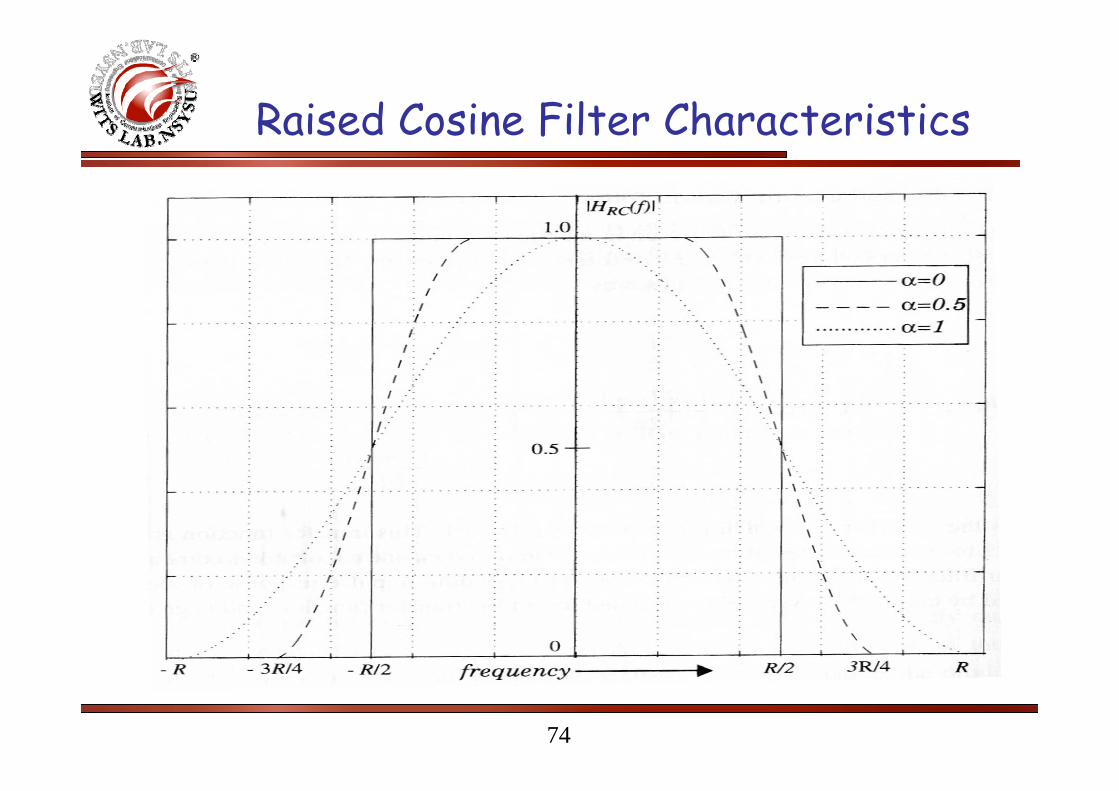
Raised Cosine Filter Characteristics

75
Raised Cosine Filter Characteristics

76
Equalization
In practical systems, the frequency response of the channel is not known to allow for a receiver design that will compensate for the ISI.The filter for handling ISI at the receiver contains various parameters that are adjusted with the channel characteristics.The process of correcting the channel-induced distortion is called equalization.

77
Equalization

78
Introduction to RAKE Receiver
Multiple versions of the transmitted signal are seen at the receiver through the propagation channels.Very low correlation between successive chips is in CDMA spreading codes.If these multi-path components are delayed in time by more than a chip duration, they appear like uncorrelated noise at a CDMA receiver.
Equalization is NOT necessary
Combine Coherently

79
Introduction to RAKE Receiver
To utilize the advantages of diversity techniques, channel parameters are necessary to be estimated.
Arrival time of each path, Amplitude, and Phase.
Maximal Ratio Combiner (MRC): The combiner that achieves the best performance is one in which each output is multiplied by the corresponding complex-valued (conjugate) channel gain. The effect of this multiplication is to compensate for the phase shift in the channel and to weight the signal by a factor that is proportional to the signal strength.

80
Maximum Ratio Combining (MRC)
MRC: Gi=Aie-jqi
Coherent Combining
Channel Estimation
Best Performance
G1
Receiver
G2 GL

81
Maximum Ratio Combining (MRC)
1
22 2,
12
21
22 2
,1
22
,1 1 ,
Received Envelope:
Total Noise Power:
SNR: 2 2
Since
L
L l ll
L
n l n ll
L
l llL
L Ln
l n ll
L Ll
l l l n ll l n l
r G r
σ G
G rrSNR
G
rG r G
σ
σ σ
σσ
=
=
=
=
= =
= ⋅
=
⋅= =
⋅ ⋅ ⋅
⎛ ⎞⋅ = ⎜ ⎟⎜ ⎟
⎝ ⎠
∑
∑
∑
∑
∑ ∑

82
Maximum Ratio Combining (MRC)
*
,
*
,
112,
2
1
2,
2
1 1
2
,
2,
1 1
2
,
2,
2
1
@ branches all from SNRs of SumSNROutput
:holdequality With
21
21
:Inequality sChebychev'
ll
ln
llnl
L
ll
L
l ln
lL
llnl
L
l
L
l ln
llnl
L
L
l
L
l ln
llnl
L
lll
rG
rkG
SNRr
G
rGSNR
rGrG
∝=⇒
=
==
⋅
≤
⋅≤⋅
∑∑∑
∑ ∑
∑ ∑∑
==
=
= =
= ==
σσ
σσ
σσ
σσ

83
Advantages of RAKE Receiver
Consider a receiver with only one finger:Once the output of a single correlator is corrupted by fading, large bit error is expected.
Consider a RAKE receiverIf the output of a single correlator is corrupted by fading, the others may NOT be.Diversity is provided by combining the outputs
Overcome fadingImprove CDMA reception


