Introduction to Cellular Networks, Challenges and Future Directions
100
Cellular Networks and Mobile Computing COMS 6998-10, Spring 2013 Instructor: Li Erran Li ([email protected]) http://www.cs.columbia.edu/~li erranli/coms6998-10Spring2013/ 2/26/2013: Introduction to Cellular Networks
Transcript of Introduction to Cellular Networks, Challenges and Future Directions

Cellular Networks and Mobile ComputingCOMS 6998-10, Spring 2013
Instructor: Li Erran Li ([email protected])
http://www.cs.columbia.edu/~lierranli/coms6998-10Spring2013/2/26/2013: Introduction to Cellular Networks

Announcements
• Programming assignment 2 will be due tomorrow
• Programming assignment 3 will be due March 13. Please start early!– Two lab sessions will be scheduled
• Please email me the presentation slides the day before!
2

Review of Previous Lecture
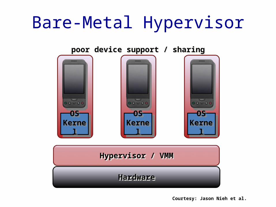
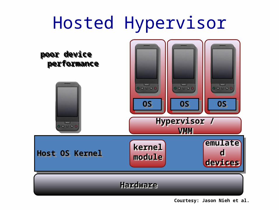
• What are the different approaches of virtualization?

Review of Previous Lecture
• What are the different approaches of virtualization?– Bear-metal hypervisor, hosted hypervisor, container
(Linux LXC, Samsung Knox)
OSKernel
OSKernel
OSKernel
Hypervisor / VMM
Hardware
Bare-Metal Hypervisorpoor device support / sharing
Courtesy: Jason Nieh et al.
OSOS
Host OS Kernel
OS
Hypervisor / VMM
Hosted Hypervisor
kernelmodule
Hardware
poor device performance
emulateddevices
Courtesy: Jason Nieh et al.

Review of Previous Lecture (Cont’d)
• What approach does Cell use?• What are the key design choices for Cell’s
extremely low overhead?

Review of Previous Lecture (Cont’d)
• Device namespace– It is designed to be used by individual device drivers or
kernel subsystems to tag data structures and to register callback functions. Callback functions are called when a device namespace changes state.
– Each VP uses a unique device namespace for device interaction.
• Cells leverages its foreground-background VP usage model to register callback functions that are called when the VP changes between foreground and background state.

LinuxKernel
Pow
er
WiF
i
Cel
l Rad
io
Fram
ebuf
fer
GPU
RTC
/ A
larm
s
•••
Sens
ors
Inpu
t
And
roid
...
Aud
io/V
ideo
•••
Device Namespacessafely, correctly
multiplex access to devices
device namespaces
VP 3VP 2VP 1
Courtesy: Jason Nieh et al.

Review of Previous Lecture (Cont’d)
• What are the most expensive flash memory operations?– Random read– Random write– Sequential write– Sequential read

Random versus Sequential Disparity
• Performance for random I/O significantly worse than seq; inherent with flash storage
• Mobile flash storage classified into speed classes based on sequential throughput
Random write performance is orders of magnitude worse
Vendor(16GB)
Speed Class
Cost US $
Seq Write
Rand Write
Transcend 2 26 4.2 1.18
RiData 2 27 7.9 0.02
Sandisk 4 23 5.5 0.70
Kingston 4 25 4.9 0.01
Wintec 6 25 15.0 0.01
A-Data 6 30 10.8 0.01
Patriot 10 29 10.5 0.01
PNY 10 29 15.3 0.01Consumer-grade SD performance
Perf
orm
ance
MB/
s
For several popular apps, substantialfraction of I/O is random writes (including web browsing!)
Courtesy: Nitin Agrawal et al.

Motion Statesitting, walking, running
Interruptibleyes, no
Logical Locationhome, office, mall
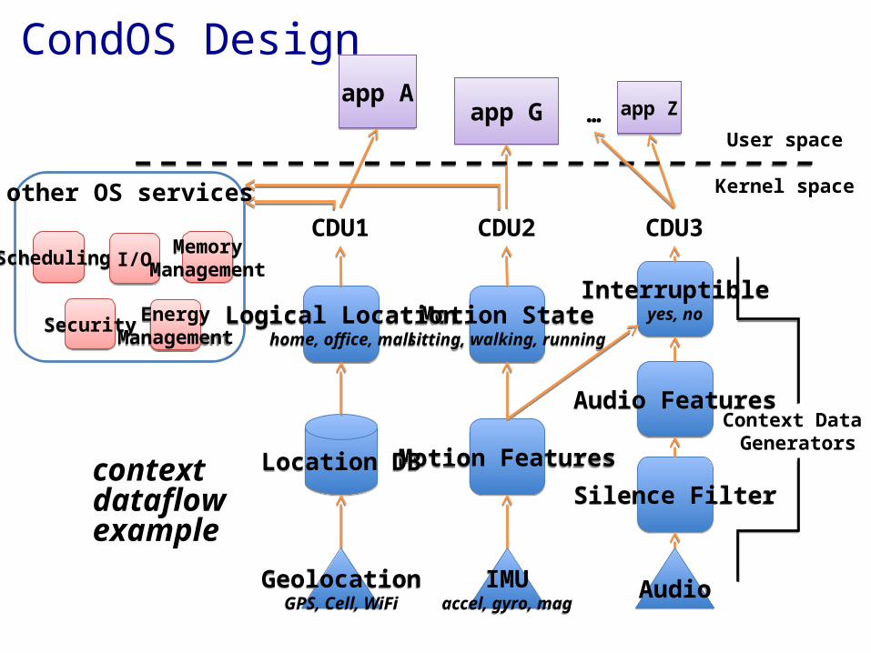
Should OS Manage Context?
• export Context Data Units (CDUs) rather than raw sensor data– higher-level abstraction than bytes– apps query or subscribe to CDUs
• each CDU is defined by a CDU Generator: a graph of processing components– combine Generators into composite context
dataflow– provide a base CDU vocabulary (that is extensible)
Motion Features
Motion Statesitting, walking, running
Audio
Audio Features
Interruptibleyes, no
CDU2 CDU3
IMUaccel, gyro, mag
Silence Filter
Logical Locationhome, office, mall
CDU1
GeolocationGPS, Cell, WiFi
Location DB
app Aapp G app Z
User space
Kernel space
…
Context Data Generators
CondOS Design
other OS services
Scheduling
Security
I/OMemory
Management
EnergyManagement
contextdataflowexample
Syllabus• Mobile App Development (lecture 1,2,3)
– Mobile operating systems: iOS and Android – Development environments: Xcode, Eclipse with Android SDK– Programming: Objective-C and android programming
• System Support for Mobile App Optimization (lecture 4,5)– Mobile device power models, energy profiling and ebug debugging– Core OS topics: virtualization, storage and OS support for power and context management
• Interaction with Cellular Networks (lecture 6,7,8) – Basics of 3G/LTE cellular networks– Mobile application cellular radio resource usage profiling– Measurement-based cellular network and traffic characterization
• Interaction with the Cloud (lecture 9,10)– Mobile cloud computing platform services: push notification, iCloud and Google Cloud
Messaging– Mobile cloud computing architecture and programming models
• Mobile Platform Security and Privacy (lecture 11,12,13)– Mobile platform security: malware detection and characterization, attacks and defenses– Mobile data and location privacy: attacks, monitoring tools and defenses
14

OutlineGoal of this lecture: understand the basics of current networks and future directions
•Current Cellular Networks– Introduction– Radio Aspects– Architecture– Power Management– Security– QoS
•What Is Next?•A Clean-Slate Design: Software-Defined Cellular Networks•Conclusion and Future Work
15

Cellular Networks Impact our Lives
More Mobile Connection
More Mobile Information
Sharing
More Mobile Users
16
10101001000010110010101010101001010100101010101010101101010100101010101010100101010101001010101
More InfrastructureDeployment

Mobile Data Tsunami Challenges Current Cellular Technologies
• Global growth 18 times from 2011 to 2016
• AT&T network:– Over the past five years,
wireless data traffic has grown 20,000%
– At least doubling every year since 2007
• Existing cellular technologies are inadequate– Fundamental redesign of
cellular networks is needed
Source: CISCO Visual Networking Index (VNI) Global Mobil Data Traffic Forecast 2011 to 2016
0
2
4
6
8
10
12
2011 2012 2013 2014 2015 2016
0.61.3
2.4
4.2
6.9
10.8
Exab
ytes
per
Mon
th
Global Mobile Data Traffic Growth2011 to 2016
Annual Growth 78%
17

Global Convergence• LTE is the major technology for future mobile
broadband– Convergence of 3GPP and 3GPP2 technology tracks– Convergence of FDD and TDD into a single technology track
GSM WCDMA HSPA
TD-SCDMA HSPA/TDDLTE
FDD and TDD
IS-95 cdma2000 EV-DO
D-AMPSD-AMPS
PDCPDC
WiMAX ?
3GPP
3GPP2
IEEE

LTE deployments89 commercial networks launched
Courtesy: Zoltán Turányi
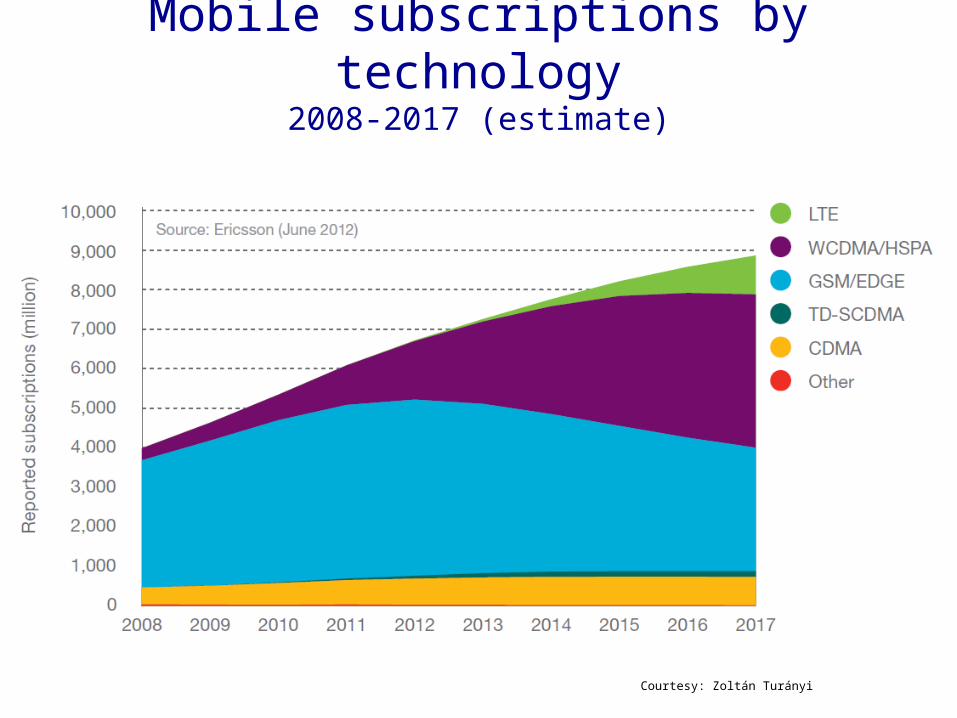
Mobile subscriptions by technology2008-2017 (estimate)
Courtesy: Zoltán Turányi

3GPP introduction• 3rd Generation Partnership Program
– Established in 1998 to define UMTS– Today also works on LTE and access-independent
IMS– Still maintains GSM
• 3GPP standardizes systems– Architecture, protocols
• Works in releases– All specifications are consistent within a release

3GPP TS 23.401 V11.2.0
Stage 1Requirements
• “It shall be possible to...”• “It shall support…”
3GPP way of working
E.g., 22-series specs
Stage 2Architecture• Nodes, functions• Reference points
• Procedures (no errors)
Stage 3Protocols
• Message formats• Error cases
E.g., 23-series specs
E.g., 29-series specs
Specification numbering example:
Spec. number
TS=Technical Specification (normative)TR=Technical Report (info only) Release
• Consistent set of specs per release• New release every 1-2 years
Updated after a meeting
Courtesy: Zoltán Turányi

3GPP specification groups2G 3G/LTE System Protocols
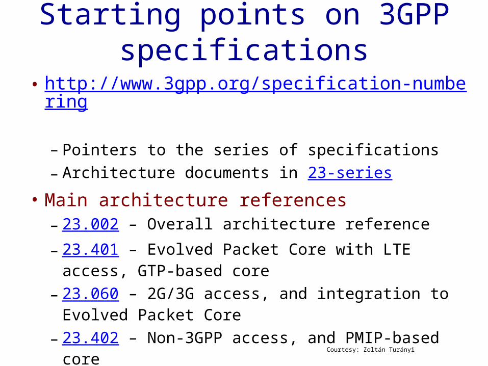
Starting points on 3GPP specifications
• http://www.3gpp.org/specification-numbering – Pointers to the series of specifications– Architecture documents in 23-series
• Main architecture references– 23.002 – Overall architecture reference– 23.401 – Evolved Packet Core with LTE access, GTP-
based core– 23.060 – 2G/3G access, and integration to Evolved
Packet Core– 23.402 – Non-3GPP access, and PMIP-based core
Courtesy: Zoltán Turányi
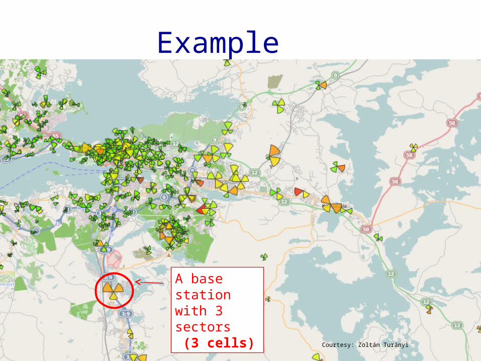
Example
A base stationwith 3 sectors (3 cells)
Courtesy: Zoltán Turányi

• Large distances– Terminals do not see each other– Tight control of power and timing needed– Highly variable radio channel – quick adaptation needed
• Many users in a cell – A UMTS cell can carry roughly 100 voice calls on 5 MHz – Resource sharing must be fine grained – but also flexible
• Quality of Service with resource management– Voice – low delay, glitch-free handovers– Internet traffic – more, more, more
• Battery consumption critical– Low energy states, wake-up procedures – Parsimonious signaling
Key challenges
Courtesy: Zoltán Turányi

Radio basics
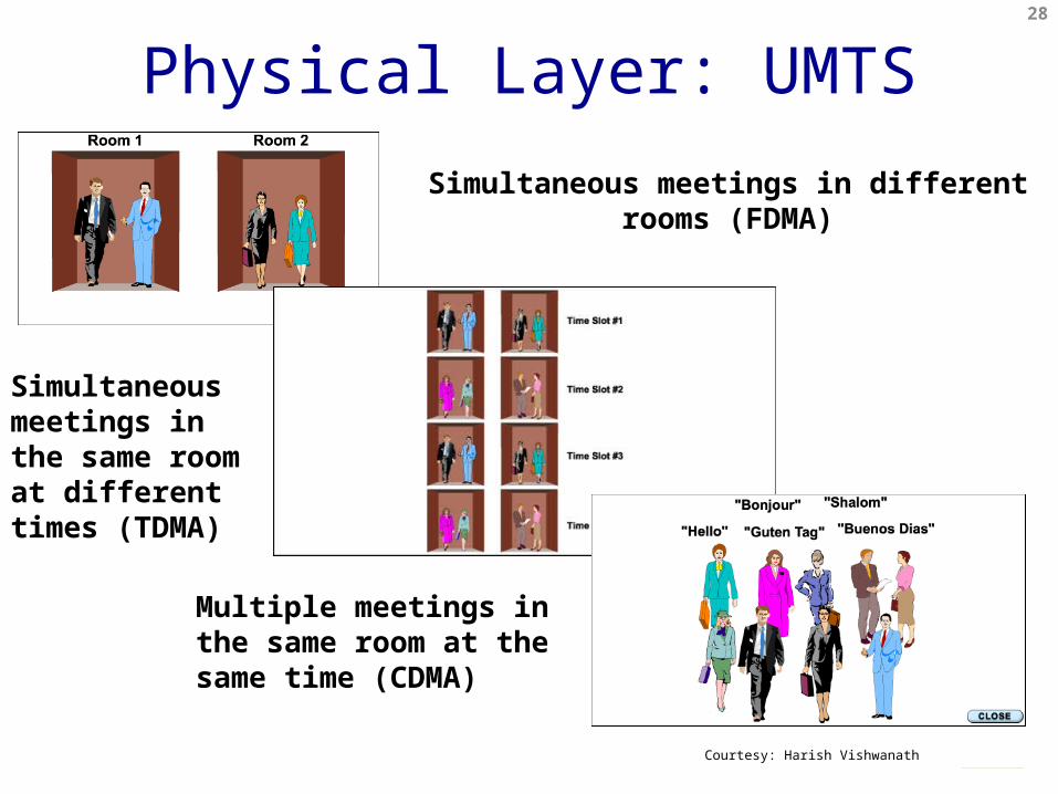
Physical Layer: UMTSSimultaneous meetings in different rooms
(FDMA)
Simultaneous meetings in the same room at different times (TDMA)
Multiple meetings in the same room at the same time (CDMA)
28
Courtesy: Harish Vishwanath

Code Division Multiple Access (CDMA) •Use of orthogonal codes to separate different transmissions•Each symbol or bit is transmitted as a larger number of bits using the user specific code – Spreading•Spread spectrum technology
– The bandwidth occupied by the signal is much larger than the information transmission rate
– Example: 9.6 Kbps voice is transmitted over 1.25 MHz of bandwidth, a bandwidth expansion of ~100
29
Courtesy: Harish Vishwanath
Physical Layer: UMTS (Cont’d)

Physical Layer: UMTS (Cont’d)• Uses spread-spectrum to separate users• Common 5 MHz channels• Supports soft-handover
– Multiple base stations send/receive same data to the user– Recombining the two paths result in better channel– Requires real-time network between base station and RNC
UMTS – Universal Mobile Telecommunication SystemCDMA – Code Division Multiple Access
UE – User EquipmentRNC – Radio Network Controller
RNC RNC RNC
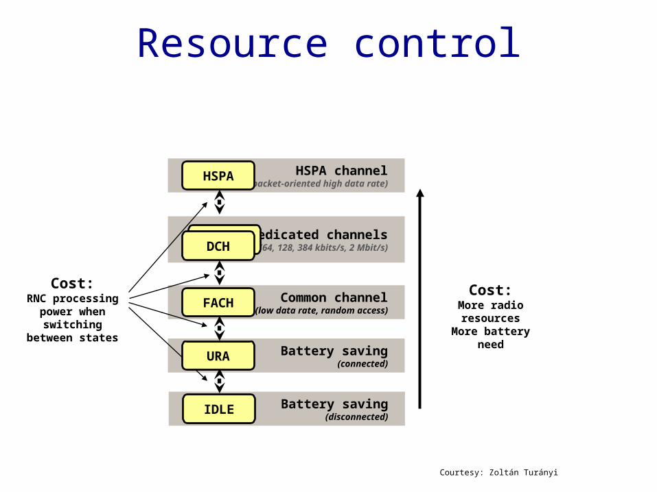
Resource control
Cost:More radio resources
More battery need
HSPA channel(packet-oriented high data rate)HSPA
Common channel(low data rate, random access)FACH
Battery saving(connected)
Battery saving(disconnected)IDLE
Cost:RNC processing
power when switching between
states
Dedicated channels(64, 128, 384 kbits/s, 2 Mbit/s)DCHDCH
URA
Courtesy: Zoltán Turányi
HSPA• High Speed Packet Access
– Packet oriented extension to WCDMA– Time Division Multiplexing within a common channel
• Opportunistic scheduling– Users with currently good reception receive more resources– Higher overall capacity than equal share
• Hybrid ARQ with soft combining– Only additional redundancy is transmitted on a frame error,
not the full frame• Most radio functions moved to NodeB• No soft handover in downlink

LTE air interface• The key improvement in LTE radio is the use of OFDM• Orthogonal Frequency Division Multiplexing
– 2D frame: frequency and time– Narrowband channels: equal fading in a channel
• Allows simpler signal processing implementations
– Sub-carriers remain orthogonal under multipath propagation
One resource element
One resource block
12 subcarriers during one slot (180 kHz × 0.5 ms)
One OFDM symbolOne slot
12 subcarriers
time
frequency
Frame (10 ms)
Subframe (1 ms)Slot (0.5 ms)
Time domain structure
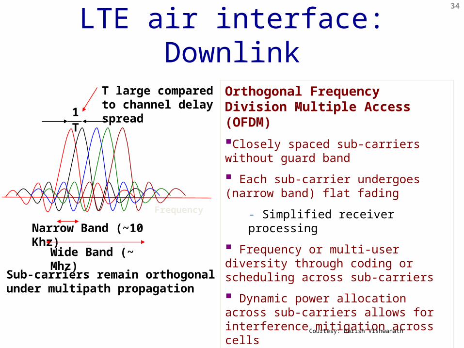
Orthogonal Frequency Division Multiple Access (OFDM)Closely spaced sub-carriers without guard band
Each sub-carrier undergoes (narrow band) flat fading
- Simplified receiver processing
Frequency or multi-user diversity through coding or scheduling across sub-carriers
Dynamic power allocation across sub-carriers allows for interference mitigation across cells
Orthogonal multiple access
Frequency
Narrow Band (~10 Khz)
Wide Band (~ Mhz)
T large compared to channel delay spread
Sub-carriers remain orthogonal under multipath propagation
T1
34
Courtesy: Harish Vishwanath
LTE air interface: Downlink

LTE air interface: UplinkUser 1
User 2
User 3
Efficient use of spectrum by multiple users
Sub-carriers transmitted by different users are orthogonal at the receiver
- No intra-cell interference
CDMA uplink is non-orthogonal since synchronization requirement is ~ 1/W and so difficult to achieve
Users are carrier synchronized to the base
Differential delay between users’ signals at the base need to be small compared to symbol duration
W
35
Courtesy: Harish Vishwanath

LTE air interface: Multiplexing
Each color represents a user Each user is assigned a
frequency-time tile which consists of pilot sub-carriers and data sub-carriers
Block hopping of each user’s tile for frequency diversity
Time
Freq
uenc
y
Typical pilot ratio: 4.8 % (1/21) for LTE for 1 Tx antenna and 9.5% for 2 Tx antennas
36
Courtesy: Harish Vishwanath
Pilot sub-carriers

• UMTS has CELL_FACH– Uplink un-synchronized
• Base station separates random access transmissions and scheduled transmissions using CDMA codes
• LTE does not have CELL_FACH– Uplink needs synchronization
• Random access transmissions will interfere with scheduled transmissions
37
LTE vs UMTS (3G): Physical Layer

• Assign each Resource Block to one of the terminals– LTE – channel-dependent scheduling in time and frequency
domain– HSPA – scheduling in time-domain only
data1data2data3data4
TimeFrequency
User #1 scheduled
User #2 scheduled
1 ms
180 kHz
Time-frequency fading, user #1Time-frequency fading, user #2
LTE Scheduling
Courtesy: Zoltán Turányi
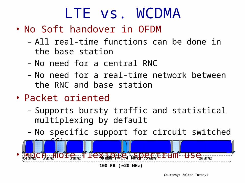
LTE vs. WCDMA• No Soft handover in OFDM
– All real-time functions can be done in the base station– No need for a central RNC– No need for a real-time network between the RNC and base
station
• Packet oriented– Supports bursty traffic and statistical multiplexing by default– No specific support for circuit switched traffic
• Much more flexible spectrum use
6 RB (1.4 MHz)100 RB (20 MHz)
10 MHz 15 MHz 20 MHz3 MHz 5 MHz1.4 MHz
Courtesy: Zoltán Turányi

Architecture
CSCN
3G Radio Access Network
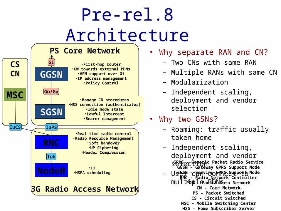
PS Core Network • Why separate RAN and CN?– Two CNs with same RAN– Multiple RANs with same CN– Modularization– Independent scaling, deployment
and vendor selection• Why two GSNs?
– Roaming: traffic usually taken home– Independent scaling, deployment
and vendor selection– User can connect to multiple PDNs
Pre-rel.8 Architecture
RNC
GGSNGn/Gp
NodeBIub
•L1•HSPA scheduling
•Real-time radio control•Radio Resource Management
•Soft handover•UP Ciphering
•Header Compression
•First-hop router•GW towards external PDNs
•VPN support over Gi•IP address management
•Policy Control
Gi
GPRS – Generic Packet Radio ServiceGGSN – Gateway GPRS Support NodeSGSN – Serving GPRS Support Node
RNC – Radio Network ControllerPDN – Packet Data Network
CN – Core NetworkPS – Packet SwitchedCS – Circuit Switched
MSC – Mobile Switching CenterHSS – Home Subscriber Server
MSC
SGSNIuPSIuCS
•Manage CN procedures•HSS connection (authenticator)
•Idle mode state•Lawful Intercept
•Bearer management
CSCN
3G Radio Access Network
PS Core Network
RNC
GGSNGn/Gp
NodeBIub
•L1•HSPA scheduling
•Real-time radio control•Radio Resource Management
•Soft handover•UP Ciphering
•Header Compression
•First-hop router•GW towards external PDNs
•VPN support over Gi•IP address management
•Policy Control
Gi
MSC
SGSNIuPSIuCS
•Manage CN procedures•HSS connection (authenticator)
•Idle mode state•Lawful Intercept
•Bearer management
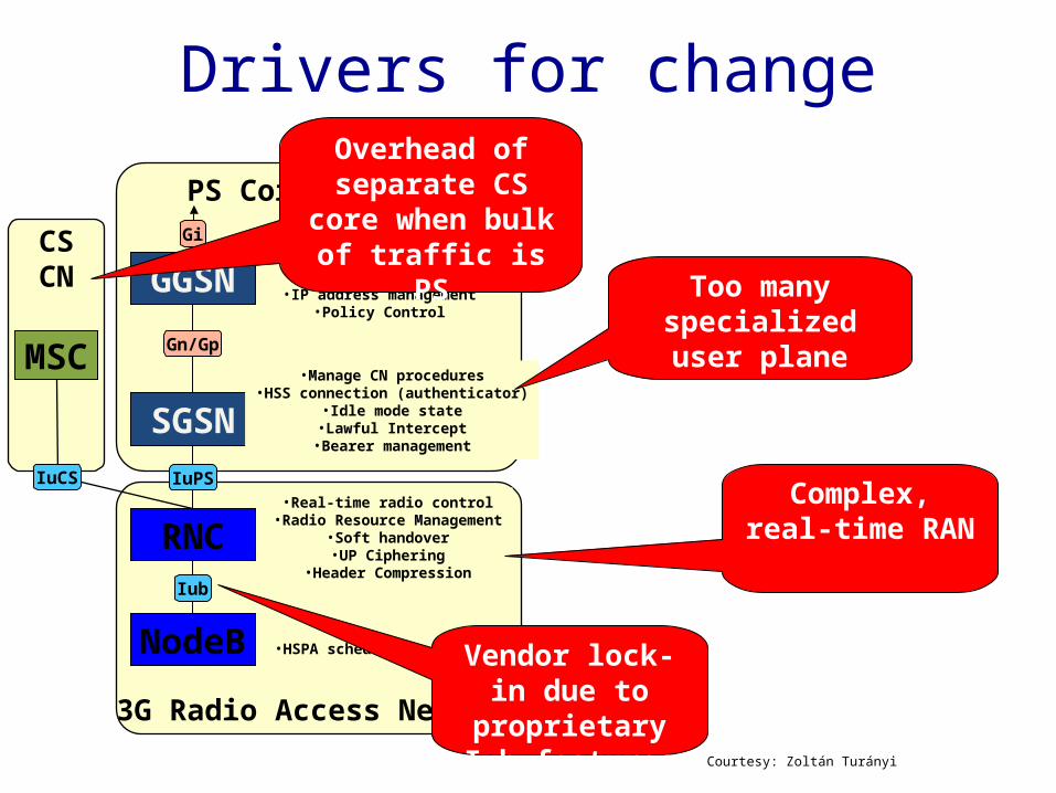
Drivers for change
Vendor lock-in due to
proprietary Iub features
Too many specialized user
plane nodes
Overhead of separate CS core
when bulk of traffic is PS
Complex, real-time RAN
Courtesy: Zoltán Turányi
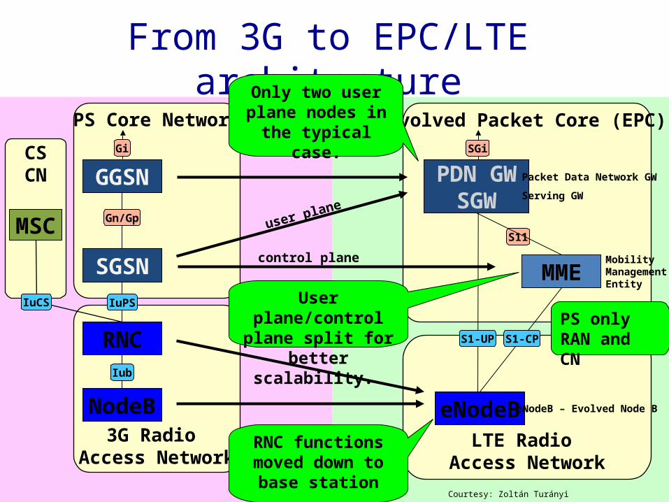
From 3G to EPC/LTE architecture
3G Radio Access Network
PS Core Network
LTE Radio Access Network
eNodeBeNodeB – Evolved Node B
RNC functions moved down to
base station
Evolved Packet Core (EPC)SGi
PDN GWSGW
S1-UP
Only two user plane nodes in the
typical case.
user plane
Packet Data Network GW
Serving GW
PS only RAN and CN
MMES11
Mobility Management Entity
User plane/control plane split for
better scalability.
control plane
S1-CP
CSCN
MSC
IuCS
RNC
GGSNGn/Gp
NodeBIub
Gi
SGSNIuPS
Courtesy: Zoltán Turányi

Why separate SGW and PDN GW?
LTE Radio Access Network
eNodeBeNodeB – Evolved Node B
Evolved Packet Core (EPC) SGi
SGW Serving GW
MMEMobility Management Entity
S1-CP
PDN GW
S1-UP
Packet Data Network GW
S11
S5/S8
SGW and PDN GW separate in some special cases:• Roaming:
• PDN GW in home network, • SGW in visited network
• Mobility to another region in a large network• Corporate connectivity
Courtesy: Zoltán Turányi

B2*: Inter-AS MM on top of GPRS CoreB1*: All accesses connected to EPC
GPRS Core
Debate of 2005: “B1 vs B2”
• Conclusion: B1.• Better integration between 3GPP accesses
• Fewer user plane entities
GERAN
UTRAN
SGSN
LTE Evolved Packet Core
Internet/Op.nw.
Non-3GPP access
GERAN
UTRAN
SGSN
LTE Evolved Packet Core
Internet/Op.nw.
Non-3GPP access
GGSN
Evolved Access
Inter-ASMM
*Note: Simplified view
Courtesy: Zoltán Turányi

Interworking with 3G
SGW
PDN GWS5
eNodeB
S1-CP
MME
S1-U
S11
SGi
HSS
MSC
RNCIuCS
NodeB
Iub
SGSNIuPS
UE MSC – Mobile Switching Center
Gn
Courtesy: Zoltán Turányi

Interworking with non-3GPP accesses
SGW
PDN GWS5
eNodeB
S1-CP
MME
S1-U
S11
SGi
HSS
MSC
RNCIuCS
NodeB
Iub
SGSNIuPS
Non-3GPP Access
(cdma2000, WiMax, WiFi)
S2
UEPMIP – Proxy Mobile IP
Gn
Courtesy: Zoltán Turányi

Debate of 2006: GTP vs. PMIP
SGW
PDN GWS5
eNodeB
S1-CP
MME
S1-U
S11
SGi
HSS
MSC
RNCIuCS
NodeB
Iub
SGSNIuPS
Non-3GPP Access
(cdma2000, WiMax, WiFi)
S2PMIP
GTP
GTP
GTP?
PMIP?
GTP
PMIP
UE
Gn
• Conclusion: Specify bothCourtesy: Zoltán Turányi

EPC + LTE: 23.401EPC + 2G/3G: 23.060
SGW
PDN GWS5
eNodeB
S1-CP
MME
S1-U
S11
SGi
HSS
MSC
RNCIuCS
NodeB
Iub
SGSNIuPS
GTP
UE
GTPGTP Gn
Courtesy: Zoltán Turányi

EPC + non-3GPP: 23.402
SGW
PDN GWS5
eNodeB
S1-CP
MME
S1-U
S11
SGi
HSS
GTP
UE
PMIP
EPC – Evolved Packet Core
Non-3GPP Access
(cdma2000, WiMax, WiFi)
S2PMIP
Courtesy: Zoltán Turányi
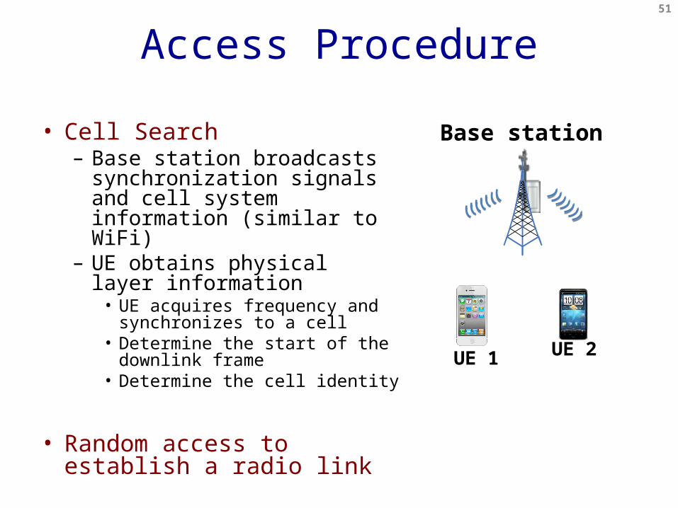
Access Procedure
• Cell Search– Base station broadcasts
synchronization signals and cell system information (similar to WiFi)
– UE obtains physical layer information
• UE acquires frequency and synchronizes to a cell
• Determine the start of the downlink frame
• Determine the cell identity
• Random access to establish a radio link
51
Base station
UE 2UE 1
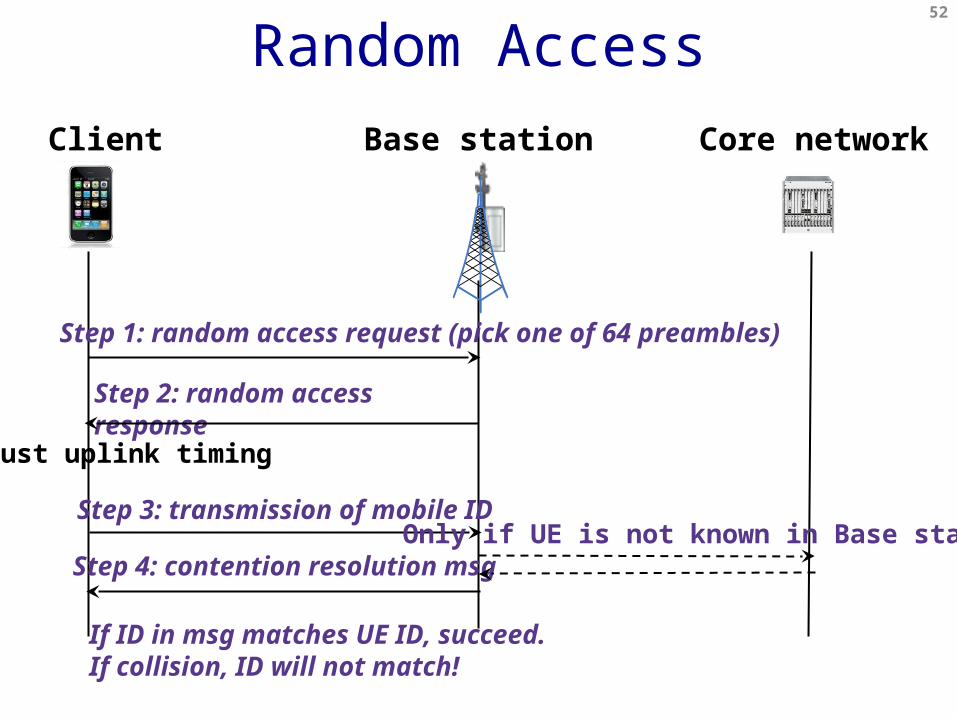
Client Base station Core network
Step 1: random access request (pick one of 64 preambles)
Step 2: random access response
Step 3: transmission of mobile ID
Step 4: contention resolution msgOnly if UE is not known in Base station
Random Access
Adjust uplink timing
If ID in msg matches UE ID, succeed.If collision, ID will not match!
52

Base station
Random Access (Cont’d)
UE 2UE 1
Why not carrier sensing like WiFi?•Base station coverage is much larger than WiFi AP
– UEs most likely cannot hear each other
•How come base station can hear UEs’ transmissions?
– Base station receivers are much more sensitive and expensive
53

Modes of operation

• Used during communication• Signaling connection exists between network and UE• Both CN and RAN keeps state about the UE• UE location is tracked on a cell granularity
– Needed to deliver the data
• Network controlled mobility
Connected mode
SGW MME

• Procedure1. UE measures nearby cells2. UE sends measurement reports to network3. Network decides on and controls handover4. Handover is prepared by network5. Handover executes
Network controlled mobility
SGW MME
1.1.
1.2.
4.3.
5
5
5
5
• Reason: To allow the network to tune handovers1. Select proper target cell2. Network has additional information for handover decision3. Collect and analyze data for cell planning and troubleshooting4. Penalize ping-ponging UEs5. Penalize microcells for fast UEs6. Cell breathing Courtesy: Zoltán Turányi

Handover ProcedureUE source eNB target eNB MME SGW PDN GW
User Data
1: Measurementreport
2: Handover decision3: Handover
Request4: Allocate TEID
5: HandoverRequest Ack
6: handovercommand
7: SN StatusTransfer
User Databuffer DL data
8: Sync+RRC complete
User Data
9: Path SwitchRequest 10: Modify Bearer
RequestUser Data end marker
stop fw stop fw
11: Modify BearerResponse12: Path Switch
Request Ack13: UE ContextRelease
http://msc-generator.sourceforge.net v3.4.18
LTE Fast PMIPv6

• Used when the UE is not communicating• UE location is tracked on a Tracking Area (TA)
granularity– eNodeBs advertise their TA– UE periodically listens to advertisements (every few
seconds)– UE sends Tracking Area Update to MME, when TA changes– TAU also sent periodically (e.g., once every 2 hours)
• No eNodeB state is kept for UE• When traffic arrives to the UE, the UE is paged
Idle Mode

• UE periodically checks if data is available for it– Wakes up, (re)selects cell, reads broadcast and the paging
channel– Exact timing is pseudo-random per UE
PAGING
› If packet arrives to SGW…– …it buffers the packet– …and notifies MME.– MME sends a Paging Request to all eNodeBs
in the TA of the UE– eNodeBs page the UE on its paging slot
locally– UE responds with a Service Request…– …eNodeB state is built up…– …and UE is moved to connected state.
SGW
PDN GW
MME
UECourtesy: Zoltán Turányi
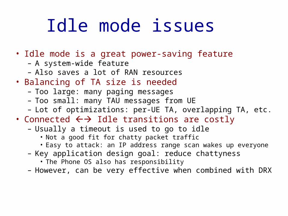
• Idle mode is a great power-saving feature– A system-wide feature– Also saves a lot of RAN resources
• Balancing of TA size is needed– Too large: many paging messages– Too small: many TAU messages from UE– Lot of optimizations: per-UE TA, overlapping TA, etc.
• Connected Idle transitions are costly– Usually a timeout is used to go to idle
• Not a good fit for chatty packet traffic• Easy to attack: an IP address range scan wakes up everyone
– Key application design goal: reduce chattyness• The Phone OS also has responsibility
– However, can be very effective when combined with DRX
Idle mode issues

LTE RRC State Machine• UE runs radio resource
control (RRC) state machine
• Two states: IDLE, CONNECTED
• Discontinuous reception (DRX): monitor one subframe per DRX cylce; receiver sleeps in other subframes
61
Courtesy:Morley Mao

UMTS RRC State Machine
• State promotions have promotion delay• State demotions incur tail times
Tail Time
Tail Time
Delay: 1.5sDelay: 2s
Channel Radio Power
IDLE Not allocated
Almost zero
CELL_FACH Shared, Low Speed
Low
CELL_DCH Dedicated, High Speed
HighCourtesy: Feng Qian
62

• IDLE: procedures based on reception rather than transmission– Reception of System Information messages – Cell selection registration (requires RRC connection
establishment) – Reception of paging messages with a DRX cycle
(may trigger RRC connection establishment)– Location and routing area updates (requires RRC
connection establishment)
63
Why Power Consumptions of RRC States so different?

• CELL_FACH: need to continuously receive (search for UE identity in messages on FACH), data can be sent by RNC any time– Can transfer small data– UE and network resource required low– Cell re-selections when a UE moves– Inter-system and inter-frequency handoff possible– Can receive paging messages without a DRX cycle
64
UMTS RRC State Machine (Cont’d)
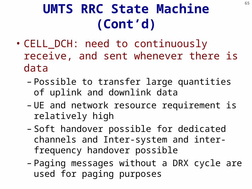
• CELL_DCH: need to continuously receive, and sent whenever there is data– Possible to transfer large quantities of uplink and
downlink data – UE and network resource requirement is relatively
high– Soft handover possible for dedicated channels and
Inter-system and inter-frequency handover possible – Paging messages without a DRX cycle are used for
paging purposes
65
UMTS RRC State Machine (Cont’d)

Security

• Subscriber Identity Module– Usually embedded in a physical SIM card
• Initially specified in 1990 for GSM (freeze date of TS 11.11)• Carries subscriber credentials
– IMSI: International Mobile Subscriber Identity – 14-15 digits• MCC: Mobile Country Code – 3 digits• MNC: Mobile Network Code – 2 or 3 digits• Rest of the digits identify the subscriber
– Keying material (essentially symmetric keys)• In the network HSS stores subscriber data
– Including keying and phone number (MSISDN)• Enables roaming and phone replacement
– Key features in GSM
The SIM card
MSISDN – Mobile Subscriber ISDN Number
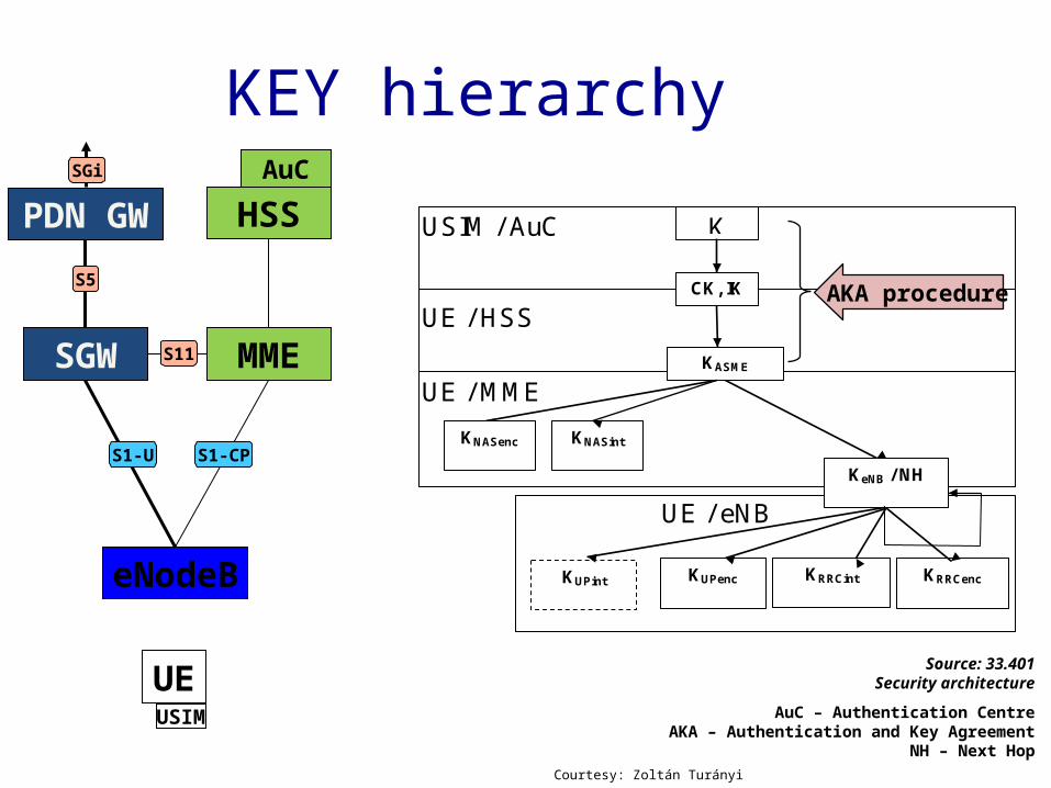
KEY hierarchy
USIM / AuC
UE / MME KASME
K
KUPenc
KeNB / NH
KNASint
UE / HSS
UE / eNB
KNASenc
CK, IK
KRRCint KRRCenc KUPint
Source: 33.401Security architecture
AuC – Authentication CentreAKA – Authentication and Key Agreement
NH – Next Hop
SGW
PDN GWS5
eNodeB
S1-CP
MME
S1-U
S11
SGi
HSS
UE
AuC
AKA procedure
USIM
Courtesy: Zoltán Turányi
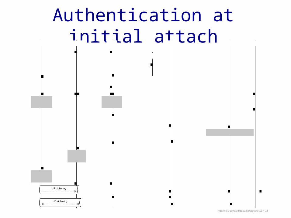
Authentication at initial attachUE eNodeB MME SGW PDN GW HSS
1: Attach Request(GUTI or IMSI) old MME
2: Identity Request(GUTI)
3: Identity Response(IMSI)
4: Identity Request(GUTI)
5: Identity Response(IMSI) 6: Security functions (incl. AKA)
7: KASME
computed8: KASME
computed 9: Update Location Request10: Update Location Ack
(subscription data)11: Create Sesstion Request 12: Create Sesstion Request
13: IP address allocation14: Create Sesstion Response15: Create Sesstion Response
16: Attach Accept+ keying
17: KeNB
received18: Attach Accept
19: KeNB
computed 20: Attach Complete
21: First uplink packet22: Modify Bearer
23: First downlink packet
http://msc-generator.sourceforge.net v3.4.18
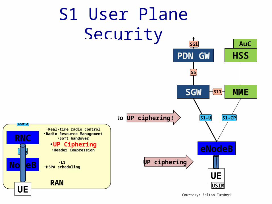
S1 User Plane Security
SGW
PDN GWS5
eNodeB
S1-CP
MME
S1-U
S11
SGi
HSS
UE
AuC
UP ciphering
USIM
No UP ciphering!
RAN
Core Network
RNC
SGSN
GGSN
IuPS
Gn/Gp
NodeBIub
•L1•HSPA scheduling
•Real-time radio control•Radio Resource Management
•Soft handover•UP Ciphering•Header Compression
•Manage CN procedures•HSS connection (authenticator)
•Idle mode state•Lawful Intercept
•Bearer management
•First-hop router•GW towards external PDNs
•VPN support over Gi•IP address management
•Policy Control
Gi
UECourtesy: Zoltán Turányi
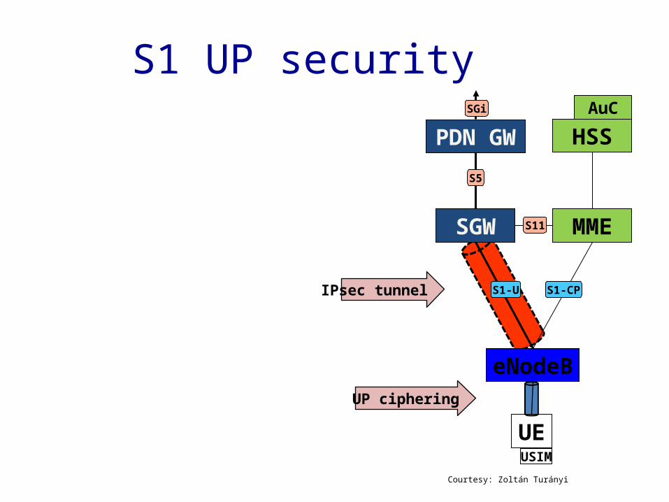
S1 UP security
SGW
PDN GWS5
eNodeB
S1-CP
MME
S1-U
S11
SGi
HSS
UE
AuC
UP ciphering
USIM
IPsec tunnel
Courtesy: Zoltán Turányi
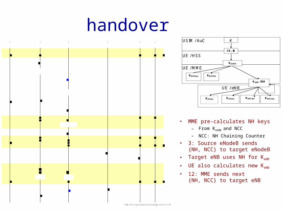
• MME pre-calculates NH keys– From KASME and NCC– NCC: NH Chaining Counter
• 3: Source eNodeB sends {NH, NCC} to target eNodeB
• Target eNB uses NH for KeNB
• UE also calculates new KeNB
• 12: MME sends next {NH, NCC} to target eNB
handoverUE source eNB target eNB MME SGW PDN GW
User Data
1: Measurementreport
2: Handover decision3: Handover
Request{NH, NCC}
4: Allocate TEID5: HandoverRequest Ack
6: handovercommand
7: SN StatusTransfer
User Databuffer DL data
8: Sync+RRC complete
User Data
9: Path SwitchRequest 10: Modify Bearer
RequestUser Data end marker
stop fw stop fw
11: Modify BearerResponse
12: Path SwitchRequest Ack
(new {NH, NCC} pair)13: UE Context
Releasehttp://msc-generator.sourceforge.net v3.4.18
USIM / AuC
UE / MME KASME
K
KUPenc
KeNB / NH
KNASint
UE / HSS
UE / eNB
KNASenc
CK, IK
KRRCint KRRCenc KUPint

QoS architecture

• Overprovisioning is difficult– Resources are scarce (few 10s of MHzs)– Equipment and spectrum expensive– You need to use well what you have
• Everything is more complicated– Due to the wide-area radio delays are higher– Primary application is delay sensitive
• Money– People are (somewhat more) willing to pay– There is an infrastructure to charge– Service and price differentiation happens
QoS MATTERS IN CELLULAR

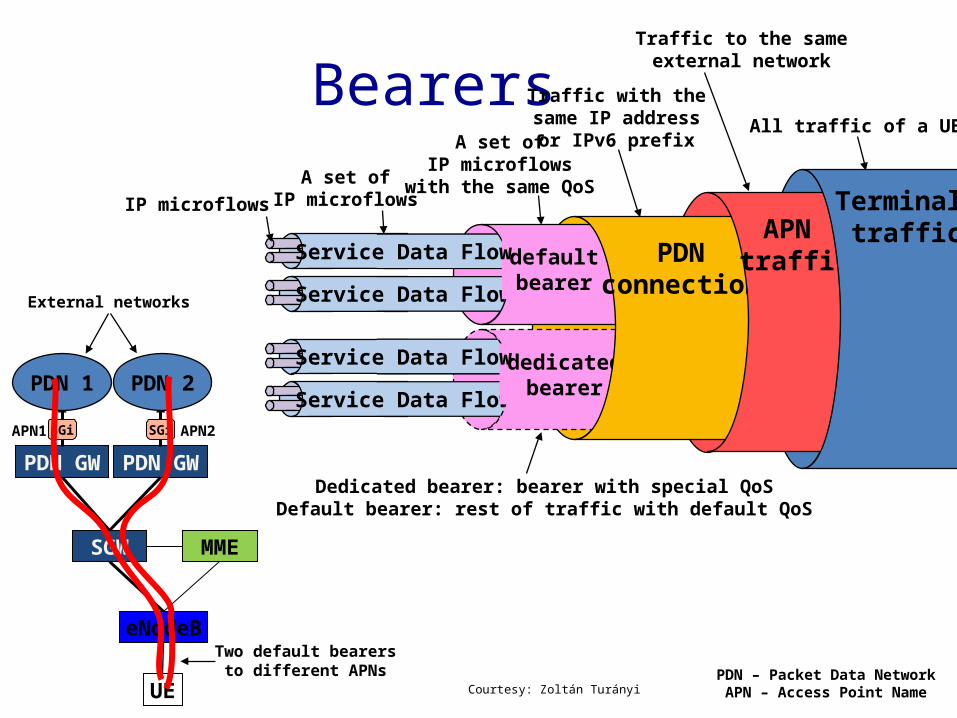
• A bearer is a L2 packet transmission channel– …to a specific external Packet Data Network,– …using a specific IP address/prefix,– …carrying a specific set of IP flows (maybe all)– …providing a specific QoS.
• In 2G/3G also known as “PDP Context”• Bearer setup is explicitly signaled
– In LTE one bearer is always set up at attachment
Bearers
SGW
PDN-GW
S5
eNodeB
S1-CP
MME
S1-U
S11
SGi
HSS
UE
See more in: 23.107QoS concept and architectureCourtesy: Zoltán Turányi
Service Data Flow
Bearers
defaultbearer
Service Data Flow
Service Data Flow
dedicatedbearer
Service Data Flow
PDNconnection
APN traffic
Terminal traffic
IP microflowsA set of
IP microflows
A set ofIP microflows
with the same QoS
Traffic with thesame IP address
or IPv6 prefix
Traffic to the sameexternal network
All traffic of a UE
Dedicated bearer: bearer with special QoSDefault bearer: rest of traffic with default QoS
SGW
PDN GW
eNodeB
MME
SGi
UE
PDN GWSGi
PDN 1 PDN 2
APN1
PDN – Packet Data NetworkAPN – Access Point Name
APN2
External networks
Two default bearersto different APNs
Courtesy: Zoltán Turányi

• Terminal apps do not use QoS– Original IP socket API has minimal QoS features
• No widespread QoS mechanism in fixed networks• Usually IP app developers do not care about network QoS
– A number of QoS API failures• Conceptual difficulties
– QoS must be authorized and charged• QoS can only be effectively decided in the face of its price
– Complex QoS descriptors• Determining QoS parameters is challenging
– E.g., 10-3 or 10-4 bit error rate?
– Yet not flexible enough to cater for e.g., VBR video
Why then no QoS?(Apart from voice)

Pre-rel.8 QoS descriptor8 7 6 5 4 3 2 1
Quality of service IEI octet 1 Length of quality of service IE Octet 2
0 0 spare
Delay class
Reliability class
octet 3
Peak throughput
0 spare
Precedence class
octet 4
0 0 0 spare
Mean throughput
octet 5
Traffic Class Delivery order Delivery of erroneous SDU
Octet 6
Maximum SDU size Octet 7 Maximum bit rate for uplink Octet 8
Maximum bit rate for downlink Octet 9 Residual BER SDU error ratio Octet 10
Transfer delay Traffic Handling priority
Octet 11
Guaranteed bit rate for uplink
Octet 12
Guaranteed bit rate for downlink Octet 13 0 0 0
spare Signal-
ling Indicat-
ion
Source Statistics Descriptor Octet 14
Maximum bit rate for downlink (extended) Octet 15 Guaranteed bit rate for downlink (extended) Octet 16
Maximum bit rate for uplink (extended) Octet 17 Guaranteed bit rate for uplink (extended) Octet 18
Delay (maximum values) SDU size: 128 octets SDU size: 1024 octets
Delay Class
Mean Transfer Delay (sec)
95 percentile Delay (sec)
Mean Transfer Delay (sec)
95 percentile Delay (sec)
1. (Predictive) < 0.5 < 1.5 < 2 < 7 2. (Predictive) < 5 < 25 < 15 < 75 3. (Predictive) < 50 < 250 < 75 < 375 4. (Best Effort) Unspecified
Maximum bit rate (octets 8-9)0 0 0 0 0 0 0 1 The maximum bit rate is binary coded in
8 bits, using a granularity of 1 kbps0 0 1 1 1 1 1 1 giving a range of values from 1 kbps to
63 kbps in 1 kbps increments.0 1 0 0 0 0 0 0 The maximum bit rate is 64 kbps + ((the
binary coded value in 8 bits –01000000) * 8 kbps)0 1 1 1 1 1 1 1 giving a range of values from 64 kbps to
568 kbps in 8 kbps increments.1 0 0 0 0 0 0 0 The maximum bit rate is 576 kbps + ((the
binary coded value in 8 bits –10000000) * 64 kbps)1 1 1 1 1 1 1 0 giving a range of values from 576 kbps
to 8640 kbps in 64 kbps increments.1 1 1 1 1 1 1 1 0kbps
If the sending entity wants to indicate a Maximum bit rate for uplink higher than 8640 kbps, it shall set octet 8
to ”11111110”, i.e. 8640 kbps, and shall encode the value for the Maximum bit rate in octet 17.
Source: 24.008Core network protocols; Stage 3
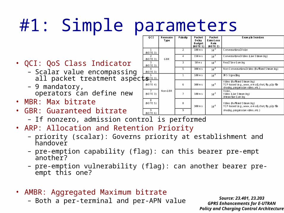
• QCI: QoS Class Indicator– Scalar value encompassing
all packet treatment aspects– 9 mandatory,
operators can define new• MBR: Max bitrate• GBR: Guaranteed bitrate
– If nonzero, admission control is performed• ARP: Allocation and Retention Priority
– priority (scalar): Governs priority at establishment and handover– pre-emption capability (flag): can this bearer pre-empt another?– pre-emption vulnerability (flag): can another bearer pre-empt this one?
• AMBR: Aggregated Maximum bitrate– Both a per-terminal and per-APN value
#1: Simple parametersQCI Resource
Type Priority Packet
Delay Budget
(NOTE 1)
Packet Error Loss
Rate (NOTE 2)
Example Services
1 (NOTE 3)
2 100 ms 10-2 Conversational Voice
2 (NOTE 3)
GBR
4 150 ms 10-3 Conversational Video (Live Streaming)
3 (NOTE 3)
3 50 ms 10-3 Real Time Gaming
4 (NOTE 3)
5 300 ms 10-6 Non-Conversational Video (Buffered Streaming)
5 (NOTE 3)
1 100 ms 10-6 IMS Signalling
6 (NOTE 4)
6
300 ms
10-6
Video (Buffered Streaming) TCP-based (e.g., www, e-mail, chat, ftp, p2p file sharing, progressive video, etc.)
7 (NOTE 3)
Non-GBR 7
100 ms
10-3
Voice, Video (Live Streaming) Interactive Gaming
8 (NOTE 5)
8
300 ms
10-6
Video (Buffered Streaming) TCP-based (e.g., www, e-mail, chat, ftp, p2p file
9 (NOTE 6)
9 sharing, progressive video, etc.)
Source: 23.401, 23.203GPRS Enhancements for E-UTRAN
Policy and Charging Control Architecture

• Allow a network application request QoS– Terminal app can remain QoS un-aware– Network can fully control QoS provided & payment charged
• First specified in Release 7 for 3G– Not all terminals support it
• Mandatory mode in LTE
#2: Network initiated bearers
App
LTE
App
LTE + EPC
UE Network
1. Session setup
2. Request QoS3. Bearersetup
No QoS API
Courtesy: Zoltán Turányi

Policy and Charging
SGW
PDN GW
S5
eNodeB
S1-MME
MME
S1-U
S11
SGi
PCRF Gx
Rx
UE
•Flow descriptor (5-tuple)•QoS descriptor•Charging rules•Gating (on/off)
•Flow descriptor (5-tuple)•Bandwidth
•Application (voice/video/etc.)App• Policy and Charging Rules
Function– Decides on QoS and
Charging– Controls gating– Service Policy Based on
• Request• Subscription data
– Makes no resource decisions
Courtesy: Zoltán Turányi

23.40223.401
Debate of 2007: On-path vs. off-path for QoS/policy in 23.402
• GTP signalling on user plane path to set up “bearers”
• Packets are marked to belong to one of the bearers
• No “bearer” with PMIP• Filters on SGW to classify into bearers
on S1• Motivation:
– Alignment with other non-3GPP accesses– Be different from GTP, experiment
Serving GW
hPCRF
Gx
S8-PMIP PDN GW
S9
Serving GW
PCRF
Gx
S8-GTP PDN GW
S1-GTP S1-GTP
vPCRF
Gxc
Filters FiltersGTP signalling
Filters FiltersGTP signalling
Filters

What Is Next?

LTE Evolution• LTE-A – meeting and exceeding IMT-Advanced
requirements– Carrier aggregation– Enhanced multi-antenna support– Relaying– Enhancements for heterogeneous deployments
LTELTE
LTE-ALTE-A
LTE-BLTE-B
LTE-CLTE-C
Rel-8Rel-9
Rel-10
Rel-11
Rel-12
Rel-13
Rel-14

LTE Evolution• LTE-B
– Work starting fall 2012• Topics (speculative)
– Device-to-device communication– Enhancements for machine-to-machine
communication– Green networking: reduce energy use– And more…
LTELTE
LTE-ALTE-A
LTE-BLTE-B
LTE-CLTE-C
Rel-8Rel-9
Rel-10
Rel-11
Rel-12
Rel-13
Rel-14

A Clean-Slate Design: Software-Defined Cellular Networks

Cellular Core Network
eNodeB 3 S-GW 2P-GW
87
S-GW 1
eNodeB 1
eNodeB 2
Internet andOther IP Networks
GTP TunnelsUE 2
UE 1
LTE Data Plane is too Centralized• UE: user equipment• eNodeB: base station• S-GW: serving
gateway• P-GW: packet data
network gateway
• Data plane is too centralized
Scalability challenges at P-GW on charging and policy enforcement!

88
LTE Control Plane is too Distributed
• Problem with Inter-technology (e.g. 3G to LTE) handoff
• Problem of inefficient radio resource allocation
User Equipment (UE) Gateway
(S-GW)
Mobility Management
Entity (MME)
Network Gateway (P-GW)
Home Subscriber
Server (HSS)
Policy Control and Charging
Rules Function (PCRF)
Station
(eNodeB)
Base Serving Packet Data
Control PlaneData Plane
• No clear separation of control plane and data plane
Advantages of SDN for Cellular Networks
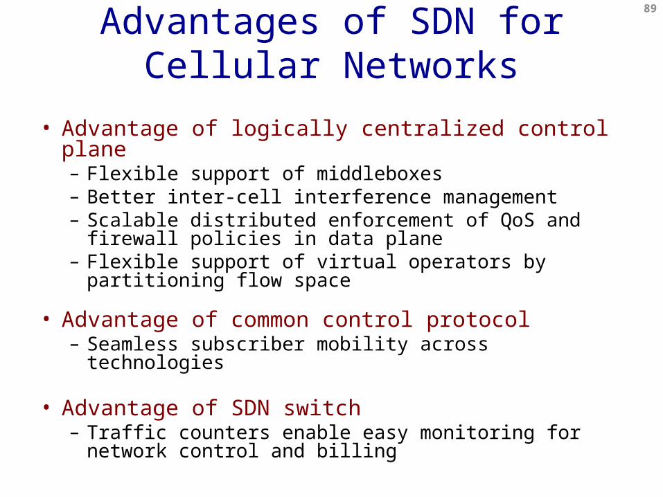
• Advantage of logically centralized control plane– Flexible support of middleboxes– Better inter-cell interference management – Scalable distributed enforcement of QoS and firewall
policies in data plane– Flexible support of virtual operators by partitioning flow
space
• Advantage of common control protocol– Seamless subscriber mobility across technologies
• Advantage of SDN switch– Traffic counters enable easy monitoring for network
control and billing
89

eNodeB 3
90
eNodeB 1
eNodeB 2
Internet andOther IP Networks
Path setup for UE by SDN controller
UE 2
UE 1
Flexible Middlebox Support
• Easy to control flow to middleboxes for content adaptation, echo cancellation, etc
• Reduce traffic to middleboxes
SDN Switch
Middlebox
• SDN provides fine grained packet classification and flexible routing

eNodeB 3
91
eNodeB 1
eNodeB 2
Internet andOther IP Networks
UE 2
UE 1
Flexible Middlebox Support (Cont’d)
• Easy to satisfy policy for traffic not leaving cellular network
• Reduce the need for extra devices
SDN Switch
Path setup for UE by SDN controller
• SDN switch can support some middlebox functionality

Monitoring for Network Control & Billing• Packet handling rules in SDN switches can efficiently monitor
traffic at different level of granularity– Enable real time control and billing
92
SwitchPort
MACsrc
MACdst
Ethtype
VLANID
IPSrc
IPDst
IPProt
TCPsport
TCPdport
Rule Action Stats
1. Forward packet to port(s)2. Encapsulate and forward to controller
3. Drop packet4. Send to normal processing pipeline
+ mask
Packet + byte counters

eNodeB 3
93
eNodeB 1
eNodeB 2
Internet andOther IP Networks
UE 2
UE 1
Seamless Subscriber Mobility• SDN provides a
common control protocol works across different cellular technologies
• Forwarding rules can be pushed to switches in parallel
SDN Switch
SDN Control Plane
Path setup for UE by SDN controller
X-Gen Cellular Network
X+1-Gen Cellular Network

eNodeB 3
94
eNodeB 1
eNodeB 2
Internet andOther IP Networks
UE 2
UE 1
Distributed QoS and ACL Enforcement
• LTE’s PCEF is centralized at P-GW which is inflexible
SDN Switch
Access policy checkedIn SDN switches distributedly
Path setup for UE by SDN controller

eNodeB 3
95
eNodeB 1
eNodeB 2
Internet andOther IP Networks
UE 2
UE 1
Virtual Operators
• Virtual operators may want to innovate in mobility, billing, charging, radio access
SDN Switch
Slicing Layer: CellVisor
Virtual Operator(VO)
(Slice 1)
Virtual Operator(Slice N)
• Flexible network virtualization by slicing flow space
VO1
VO2

eNodeB 3
96
eNodeB 1
eNodeB 2
Internet andOther IP Networks
UE 2
UE 1
Inter-Cell Interference Management
• LTE distributed interference management is suboptimal
SDN Switch
Network Operating System: CellOS
Radio Resource Manager
• Central base station control: better interference management
Global view and more computing
power

CellSDN Architecture
• CellSDN provides scalable, fine-grain real time control with extensions:– Controller: fine-grain policies on subscriber
attributes– Switch software: local control agents to improve
control plane scalability– Switch hardware: fine-grain packet processing to
support DPI– Base stations: remote control and virtualization to
enable flexible real time radio resource management
97
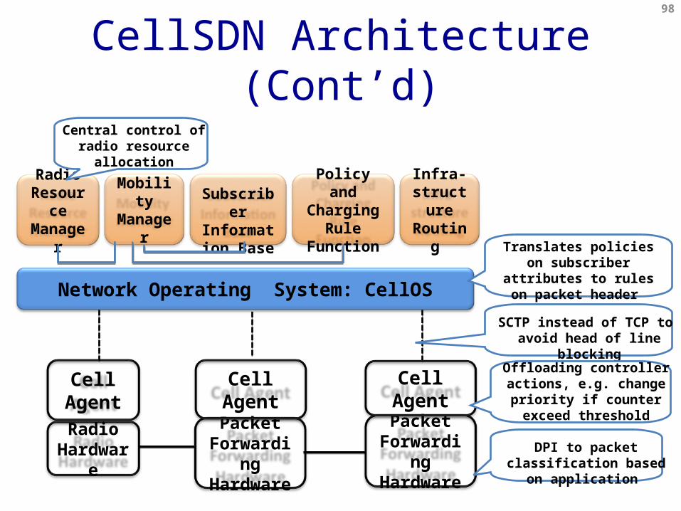
Mobility Manager
Subscriber Information
Base
Policy and Charging
Rule Function
Network Operating System: CellOS
Infra-structure Routing
Cell Agent
Radio Hardware
Packet Forwarding Hardware
Cell Agent
Radio Resource Manager
Packet Forwarding Hardware
Cell Agent
CellSDN Architecture (Cont’d)98
DPI to packet classification based on application
SCTP instead of TCP to avoid head of line blocking
Offloading controller actions, e.g. change priority if counter exceed threshold
Translates policies on subscriber attributes to rules on packet header
Central control of radio resource allocation

Cell Agent
Radio Hardware
Packet Forwarding Hardware
Cell Agent
Packet Forwarding Hardware
Cell Agent
CellSDN Virtualization99
Slicing Layer: CellVisor
Network OS (Slice 1)
Network OS (Slice 2)
Network OS (Slice N)
Slice semantic space, e.g. all roaming subscribers, all iPhone users

Conclusion and Future Work
• LTE promises hundreds of Mbps and 10s msec latency
• There are key architecture problems need to be solved– Software-defined networking can help!
100