Introduction to ANSYS Mechanical -...
15
© 2014 ANSYS, Inc. February 12, 2014 1 Release 15.0 Introduction to ANSYS Mechanical 15.0 Release Workshop 6.2 Using Joints
-
Upload
nguyennhan -
Category
Documents
-
view
276 -
download
4
Transcript of Introduction to ANSYS Mechanical -...

© 2014 ANSYS, Inc. February 12, 2014 1 Release 15.0
Introduction to ANSYS Mechanical
15.0 Release
Workshop 6.2 Using Joints

© 2014 ANSYS, Inc. February 12, 2014 2 Release 15.0
Goals The goal of this workshop is to use joints to connect some parts in an assembly instead of contact. Joints can provide a convenient alternative to contact.
The 4 part assembly shown here would normally be connected using contact definitions. In this workshop the model contains a single contact region. We’ll use the automatic joint feature to setup the remainder of the connections and make several modifications before solving.

© 2014 ANSYS, Inc. February 12, 2014 3 Release 15.0
Project Schematic Begin a new Workbench session and, from the Project page, choose “Restore Archive . . . “ and browse to the file “Joint_Connection.wbpz” and Open (location provided by instructor).
When prompted, “Save” using the default name in the same location as the archive file.
From the “Units” menu verify:
• Project units are set to “Metric (kg, mm, s, ºC, mA, N, mV).
• “Display Values in Project Units” is checked (on).
© 2014 ANSYS, Inc. February 12, 2014 4 Release 15.0
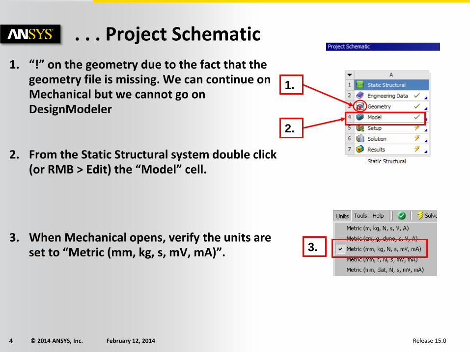
. . . Project Schematic
1. “!” on the geometry due to the fact that the geometry file is missing. We can continue on Mechanical but we cannot go on DesignModeler
2. From the Static Structural system double click (or RMB > Edit) the “Model” cell.
3. When Mechanical opens, verify the units are set to “Metric (mm, kg, s, mV, mA)”.
3.
2.
1.

© 2014 ANSYS, Inc. February 12, 2014 5 Release 15.0
Preprocessing
3. Highlight the Connections branch. Notice that currently there is a bonded contact region between the Piston and Pin parts.
4. From the Connections branch, RMB > Insert > Connection Group.
5. In the connection group details change the connection type to “Joint”.
5.
4.
3.

© 2014 ANSYS, Inc. February 12, 2014 6 Release 15.0
. . . Preprocessing 6. Highlight the “Joints” branch, RMB > Create
Automatic Connections”.
You should see 4 new joints have been created. Before inspecting the joints, we’ll rename them to make the process easier.
7. Highlight the Joints branch, RMB > Rename Based on Definition.
6.
7.

© 2014 ANSYS, Inc. February 12, 2014 7 Release 15.0
. . . Preprocessing 8. Highlight the “Crank To Con_Rod” joint.
– A revolute joint has been defined between the crank and the connecting rod. We’ll keep this as it is.
9. Highlight the “Con_Rod To Pin” joint.
– A revolute joint has been defined here which we will also keep.
8.
9.

© 2014 ANSYS, Inc. February 12, 2014 8 Release 15.0
. . . Preprocessing Highlight the “Pin To Piston” joint.
– Notice in the Contacts branch there is a contact region already defined between these parts (“Bonded – Pin to Piston”). This joint can be removed.
10. Highlight the joint “Revolute – Pint To Piston” > RMB > Delete.
11. Highlight the “Fixed - Con_Rod To Piston” joint, RMB > Delete the fixed joint.
– A fixed joint has been defined between 2 adjacent faces. This joint is not only unnecessary, it will prevent proper motions in the assembly.
10.
11.

© 2014 ANSYS, Inc. February 12, 2014 9 Release 15.0
Environment 12. Highlight the Static Structural branch.
13. Highlight the tapered cylindrical face on the crank shown here.
14. RMB > Insert > Fixed Support.
13.
14.
12.

© 2014 ANSYS, Inc. February 12, 2014 10 Release 15.0
. . . Environment 15. Highlight the cylindrical face on the crank shown
here.
16. RMB > Insert > Cylindrical Support.
17. In the details configure:
• Radial = Fixed
• Axial = Free
• Tangential = Free
15.
16.
17.

© 2014 ANSYS, Inc. February 12, 2014 11 Release 15.0
. . . Environment 18. Highlight the cylindrical face on the piston shown
here.
19. RMB > Insert > Frictionless Support.
20. Highlight the circular top face on the piston shown here.
21. RMB > Insert > Pressure.
22. In the details enter a Magnitude = 0.5 MPa.
18.
22.
20.
19.
21.
© 2014 ANSYS, Inc. February 12, 2014 12 Release 15.0
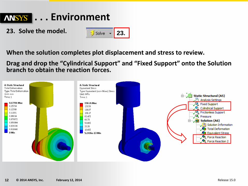
. . . Environment 23. Solve the model.
When the solution completes plot displacement and stress to review.
Drag and drop the “Cylindrical Support” and “Fixed Support” onto the Solution branch to obtain the reaction forces.
23.

© 2014 ANSYS, Inc. February 12, 2014 13 Release 15.0
. . . Environment Let’s review the loading to determine if the forces balance:
• Highlighting the top face of the piston shows (in the status bar), the approximate surface area is 9740 mm².
• Applying a 0.5 Mpa pressure should result in an approximate applied force of 4870 N in the –Y direction.
Reviewing the details for the reactions we see:
• Y reaction at the fixed support = 3963 N
• Y reaction at the cylindrical support = 962 N
• Total Y reaction (3963 + 962) = 4925
Note, using a default mesh may result in slight differences in your results compared to those here. The difference here, (~55 N) represents approximately a 1% difference.

© 2014 ANSYS, Inc. February 12, 2014 14 Release 15.0
To go further (Reaction of a joint) • Replace the cylindrical support and the fixed support by a fixed Joint.
• Reaction Force and Reaction Moment of the fixed joint can be post processed directly. Drag and Drop the fixed joint to the Solution.

© 2014 ANSYS, Inc. February 12, 2014 15 Release 15.0
To go further (Joint load) • Replace the fixed joint previously created by a Revolute joint. Drag and Drop the
revolute joint to the Static Structural, and define a Moment of 4e5 N.mm.
• Suppress the pressure and add a fixed support on the top face of the piston.

![Ansys Kurulumu - bim.yildiz.edu.tr · Documentation Only' Install MPI for ANSYS ... ANSYS ANSYS F ANSYS ANSYS AIM (V] ANSYS AP-SYS CFO [V) ANSYS ore S . msys Realize Product Promise"](https://static.fdocuments.net/doc/165x107/5b69d01e7f8b9a422e8b4fb9/ansys-kurulumu-bim-documentation-only-install-mpi-for-ansys-ansys-ansys.jpg)