Aluminum and Aluminum Alloys Miutary Standardizationhandbook

Introduction to Aluminum Alloys andTempers
J. Gilbert Kaufman
ASM International®Materials Park, OH 44073-0002
www.asminternational.org
© 2000 ASM International. All Rights Reserved.Introduction to Aluminum Alloys and Tempers (#06180)
www.asminternational.org

Copyright © 2000by
ASM International®All rights reserved
No part of this book may be reproduced, stored in a retrieval system, or transmitted, in any form or by anymeans, electronic, mechanical, photocopying, recording, or otherwise, without the written permission of thecopyright owner.
First printing, November 2000
Great care is taken in the compilation and production of this Volume, but it should be made clear that NOWARRANTIES, EXPRESS OR IMPLIED, INCLUDING, WITHOUT LIMITATION, WARRANTIES OFMERCHANTABILITY OR FITNESS FOR A PARTICULAR PURPOSE, ARE GIVEN IN CONNECTIONWITH THIS PUBLICATION. Although this information is believed to be accurate by ASM, ASM cannotguarantee that favorable results will be obtained from the use of this publication alone. This publication isintended for use by persons having technical skill, at their sole discretion and risk. Since the conditions of productor material use are outside of ASM’s control, ASM assumes no liability or obligation in connection with any useof this information. No claim of any kind, whether as to products or information in this publication, and whetheror not based on negligence, shall be greater in amount than the purchase price of this product or publication inrespect of which damages are claimed. THE REMEDY HEREBY PROVIDED SHALL BE THE EXCLUSIVEAND SOLE REMEDY OF BUYER, AND IN NO EVENT SHALL EITHER PARTY BE LIABLE FORSPECIAL, INDIRECT OR CONSEQUENTIAL DAMAGES WHETHER OR NOT CAUSED BY OR RESULT-ING FROM THE NEGLIGENCE OF SUCH PARTY. As with any material, evaluation of the material underend-use conditions prior to specification is essential. Therefore, specific testing under actual conditions isrecommended.
Nothing contained in this book shall be construed as a grant of any right of manufacture, sale, use, orreproduction, in connection with any method, process, apparatus, product, composition, or system, whether or notcovered by letters patent, copyright, or trademark, and nothing contained in this book shall be construed as adefense against any alleged infringement of letters patent, copyright, or trademark, or as a defense against liabilityfor such infringement.
Comments, criticisms, and suggestions are invited, and should be forwarded to ASM International.
ASM International staff who worked on this project included Veronica Flint, Manager, Book Acquisitions;Bonnie Sanders, Manager, Production; Carol Terman, Copy Editor; Kathy Dragolich, Production Supervisor;and Scott Henry, Assistant Director, Reference Publications.
Library of Congress Cataloging-in-Publication Data
Kaufman, J. G. (John Gilbert), 1931-Introducton to aluminum alloys and tempers / J. Gilbert Kaufman.
p. cm.Includes bibliographical references and index.
1. Aluminum alloys. 2. Metals—Heat treatment. I. Title.TA480.A6 K36 2000 620.1’86—dc21 00-056544
ISBN 0-87170-689-XSAN: 204-7586
ASM International®Materials Park, OH 44073-0002http://www.asminternational.org
Printed in the United States of America
© 2000 ASM International. All Rights Reserved.Introduction to Aluminum Alloys and Tempers (#06180)
www.asminternational.org

Contents
Preface . . . . . . . . . . . . . . . . . . . . . . . . . . . . . . . . . . . . . . . . . vii
CHAPTER 1: Introduction: The Nature of the Problem . . . . . . . 1
The Keys to Understanding. . . . . . . . . . . . . . . . . . . . . . . . . . . 2Characteristics of Wrought Aluminum Alloys. . . . . . . . . . . . . . . 3Characteristics of Cast Aluminum Alloys. . . . . . . . . . . . . . . . . . 5Definitions for Aluminum and Aluminum Alloys. . . . . . . . . . . . . 5Applications of Aluminum Alloys. . . . . . . . . . . . . . . . . . . . . . . 7Microscopy of Aluminum and Aluminum Alloys. . . . . . . . . . . . . 7Units and Unit Conversion. . . . . . . . . . . . . . . . . . . . . . . . . . . . 7
CHAPTER 2: Aluminum Alloy and Temper DesignationSystems of the Aluminum Association . . . . . . . . . . . . . . . . 9
Wrought Aluminum Alloy Designation System . .. . . . . . . . . . . 10Cast Aluminum Alloys Designation System. . . . . . . . . . . . . . . 11Designations for Experimental Aluminum Alloys. . . . . . . . . . . . 16Aluminum Alloy Temper Designation System. . . . . . . . . . . . . . 16
Basic Temper Designations .. . . . . . . . . . . . . . . . . . . . . . . . 16Subdivisions of the Basic Tempers. . . . . . . . . . . . . . . . . . . . 17
Summary. . . . . . . . . . . . . . . . . . . . . . . . . . . . . . . . . . . . . . . 22
CHAPTER 3: Understanding Wrought and CastAluminum Alloys Designations . . . . . . . . . . . . . . . . . . . . . 23
The Wrought Alloy Series. . . . . . . . . . . . . . . . . . . . . . . . . . . 23How the System is Applied. . . . . . . . . . . . . . . . . . . . . . . . . 23Principal Alloying Elements. . . . . . . . . . . . . . . . . . . . . . . . 25Understanding Wrought Alloy Strengthening
Mechanisms. . . . . . . . . . . . . . . . . . . . . . . . . . . . . . . . . . 25Understanding Wrought Alloy Advantages and
Limitations . . . . . . . . . . . . . . . . . . . . . . . . . . . . . . . . . . 26Other Characteristics Related to Principal Alloying
Element. . . . . . . . . . . . . . . . . . . . . . . . . . . . . . . . . . . . 28Understanding Wrought Alloy Variations. . . . . . . . . . . . . . . . 30Links to Earlier Alloy Designations. . . . . . . . . . . . . . . . . . . 31Unified Numbering System (UNS) Alloy Designation
System for Wrought Alloys. . . . . . . . . . . . . . . . . . . . . . . 31The Cast Alloy Series . .. . . . . . . . . . . . . . . . . . . . . . . . . . . . 32
iii
© 2000 ASM International. All Rights Reserved.Introduction to Aluminum Alloys and Tempers (#06180)
www.asminternational.org

How the Current Aluminum Cast Alloy DesignationSystem is Applied. . . . . . . . . . . . . . . . . . . . . . . . . . . . . . 32
Understanding Cast Alloy Strengthening Mechanisms. . . . . . . 33Understanding Cast Alloy Advantages and Limitations. . . . . . 34Examples of the Use of Variations in Cast Alloy
Designations. . . . . . . . . . . . . . . . . . . . . . . . . . . . . . . . . 35Alloys for Different Casting Processes. . . . . . . . . . . . . . . . . 35Other Characteristics Related to Composition. . . . . . . . . . . . 35Evolution of the Aluminum Cast Alloy Designation
System. . . . . . . . . . . . . . . . . . . . . . . . . . . . . . . . . . . . . 35UNS Alloy Designation System for Cast Alloys. . . . . . . . . . . 36
CHAPTER 4: Understanding the Aluminum TemperDesignation System . . . . . . . . . . . . . . . . . . . . . . . . . . . . . 39
Tempers for Wrought Aluminum Alloys. . . . . . . . . . . . . . . . . . 39Review of the Basic Tempers for Wrought Alloys. . . . . . . . . 57Subdivisions of the Basic Tempers. . . . . . . . . . . . . . . . . . . . 60Tempers Designating Residual Stress Relief of Heat
Treated Products. . . . . . . . . . . . . . . . . . . . . . . . . . . . . . . 67Temper Designations Identifying Modifications in
Quenching. . . . . . . . . . . . . . . . . . . . . . . . . . . . . . . . . . . 68Designations Indicating Heat Treatment by User. . . . . . . . . . 68Tempers Identifying Additional Cold Work between
Quenching and Aging. . . . . . . . . . . . . . . . . . . . . . . . . . . 70Tempers Identifying Additional Cold Work Following
Aging . . . . . . . . . . . . . . . . . . . . . . . . . . . . . . . . . . . . . . 70Tempers Designating Special Corrosion-Resistant
Tempers. . . . . . . . . . . . . . . . . . . . . . . . . . . . . . . . . . . . 71Temper Designation for Special or Premium Properties. . . . . . 71
Tempers for Cast Aluminum Alloys. . . . . . . . . . . . . . . . . . . . . 73Review of the Basic Tempers for Cast Alloys. . . . . . . . . . . . 73Subdivisions of the Basic Temper Types for
Cast Alloys. . . . . . . . . . . . . . . . . . . . . . . . . . . . . . . . . . 74Importance to Understanding Aluminum Tempers. . . . . . . . . . . 76
CHAPTER 5: Understanding Aluminum FabricatingProcesses . . . . . . . . . . . . . . . . . . . . . . . . . . . . . . . . . . . . 77
Ingot and Billet Casting . .. . . . . . . . . . . . . . . . . . . . . . . . . . . 77Strip and Slab Casting. . . . . . . . . . . . . . . . . . . . . . . . . . . . . . 78Hot and Cold Rolling. . . . . . . . . . . . . . . . . . . . . . . . . . . . . . 78Extrusion. . . . . . . . . . . . . . . . . . . . . . . . . . . . . . . . . . . . . . . 79Forging . . . . . . . . . . . . . . . . . . . . . . . . . . . . . . . . . . . . . . . . 79Cast Parts. . . . . . . . . . . . . . . . . . . . . . . . . . . . . . . . . . . . . . . 80
Permanent Mold Casting. . . . . . . . . . . . . . . . . . . . . . . . . . . 80Sand Casting. . . . . . . . . . . . . . . . . . . . . . . . . . . . . . . . . . . 81
iv
© 2000 ASM International. All Rights Reserved.Introduction to Aluminum Alloys and Tempers (#06180)
www.asminternational.org

Investment Casting. . . . . . . . . . . . . . . . . . . . . . . . . . . . . . . 82Die Casting. . . . . . . . . . . . . . . . . . . . . . . . . . . . . . . . . . . . 83
Combinations of Casting and Forging. . . . . . . . . . . . . . . . . . . 84Heat Treatment of Aluminum Alloys. . . . . . . . . . . . . . . . . . . . 84
CHAPTER 6: Applications for Aluminum Alloys andTempers . . . . . . . . . . . . . . . . . . . . . . . . . . . . . . . . . . . . . 87
Applications by Alloy Class. . . . . . . . . . . . . . . . . . . . . . . . . . 87Wrought Alloys . . . . . . . . . . . . . . . . . . . . . . . . . . . . . . . . . 87Cast Alloys. . . . . . . . . . . . . . . . . . . . . . . . . . . . . . . . . . . 108
Applications by Market Area. . . . . . . . . . . . . . . . . . . . . . . . . 115Electrical Markets. . . . . . . . . . . . . . . . . . . . . . . . . . . . . . 115Building and Construction Markets. . . . . . . . . . . . . . . . . . . 116Transportation Applications. . . . . . . . . . . . . . . . . . . . . . . . 116Marine Transportation. . . . . . . . . . . . . . . . . . . . . . . . . . . . 117Rail Transportation .. . . . . . . . . . . . . . . . . . . . . . . . . . . . . 117Packaging Applications. . . . . . . . . . . . . . . . . . . . . . . . . . . 118Petroleum and Chemical Industry Components. . . . . . . . . . . 118Other Markets. . . . . . . . . . . . . . . . . . . . . . . . . . . . . . . . . 118
CHAPTER 7: Representative Micrographs . . . . . . . . . . . . . . . 119
Wrought Aluminum Alloys. . . . . . . . . . . . . . . . . . . . . . . . . . 120Welded Wrought Aluminum Alloys. . . . . . . . . . . . . . . . . . . . 153Brazed Joints. . . . . . . . . . . . . . . . . . . . . . . . . . . . . . . . . . . 162Cast Aluminum Alloys. . . . . . . . . . . . . . . . . . . . . . . . . . . . . 164Welded Cast Aluminum Alloys. . . . . . . . . . . . . . . . . . . . . . . 181Welded Wrought-To-Cast Alloys. . . . . . . . . . . . . . . . . . . . . . 182Welded Aluminum To Steel. . . . . . . . . . . . . . . . . . . . . . . . . 184Welded Aluminum to Copper. . . . . . . . . . . . . . . . . . . . . . . . 184
CHAPTER 8: Selected References . . . . . . . . . . . . . . . . . . . . . 185
APPENDIX . . . . . . . . . . . . . . . . . . . . . . . . . . . . . . . . . . . . . 187
Subject Index . . . . . . . . . . . . . . . . . . . . . . . . . . . . . . . . . . . 225
Alloy Index . . . . . . . . . . . . . . . . . . . . . . . . . . . . . . . . . . . . . 243
Cast Alloys. . . . . . . . . . . . . . . . . . . . . . . . . . . . . . . . . . . . . 243Wrought Alloys . . . . . . . . . . . . . . . . . . . . . . . . . . . . . . . . . . 248
v
© 2000 ASM International. All Rights Reserved.Introduction to Aluminum Alloys and Tempers (#06180)
www.asminternational.org
ASM InternationalTechnical Books
Committee (1999-2000)
Sunniva R. Collins (Chair)Swagelok/Nupro Company
Eugen AbramoviciBombadier Aerospace (Canadair)
A.S BrarSeagate Technology Inc.
Ngai Mun ChowDet Norske Veritas Pte Ltd.
Seetharama C. DeeviPhillip Morris, USA
Bradley J. DiakQueen’s University
Dov B. GoldmanPrecision World Products
James F.R. GrochmalMetallurgical Perspectives
Nguyen P. HungNanyang Technological University
Serope KalpakjianIllinois Institute of Technology
Gordon LippaNorth Star Casteel
Jacques MasounaveUniversité du Québec
Charles A. Parker (Vice Chair)AlliedSignal Aircraft Landing
SystemsK. Bhanu Sankara Rao
Indira Gandhi Centre for AtomicResearch
Mel M. SchwartzSikorsky Aircraft Corporation
(retired)Peter F. Timmins
University College of the FraserValley
George F. Vander VoortBuehler Ltd.
vi
© 2000 ASM International. All Rights Reserved.Introduction to Aluminum Alloys and Tempers (#06180)
www.asminternational.org
Preface
The idea for this timely reference book was originally suggested byTom Croucher, a California-based consulting metallurgist. Dr. Croucherand Harry Chandler of ASM International provided input for the first draftversion. I broadened it out substantially to cover the understanding of theadvantages and limitations of aluminum alloy/temper combinations interms of the relationship of their composition, process history, andmicrostructure to service requirements.
I would like to acknowledge Dr. John A. S. Green and the AluminumAssociation, Inc. for making available critically important material forinclusion in this book. Among the Aluminum Association publicationsused as key references, notably on the alloy and temper designationsystem and aluminum terminology, were the following:
O Aluminum Standards and DataO Standards for Aluminum Sand and Permanent Mold CastingsO Aluminum: Technology, Applications, and Environment
More complete citations to these and other reference materials are givenin the Selected References, Chapter 8.
Among the ASM International books used as major sources, mostnotably for micrographs, are the following:
O Heat Treater’s Guide: Practices and Procedures for Nonferrous AlloysO ASM Specialty Handbook: Aluminum and Aluminum Alloys
Finally, I want to acknowledge the publications of the AmericanFoundrymen’s Society, Inc. and the Diecasting Development Council,whose publicationsAluminum Casting Technologyand Product Designfor Die Casting, respectively, provided excellent resources for castingterminology and descriptions of casting procedures.
J. Gilbert KaufmanColumbus, Ohio
vii
© 2000 ASM International. All Rights Reserved.Introduction to Aluminum Alloys and Tempers (#06180)
www.asminternational.org

CHAPTER 1Introduction: The
Nature of the Problem
THE NEED FOR THIS BOOK stems directly from the increasing useof aluminum and aluminum alloys in automobiles and a great variety ofother products that we encounter in everyday living. The excellentcombination of light weight, high strength, great corrosion resistance, andreasonable cost has made aluminum and its alloys one of the mostcommonly used metal groups. Whereas weight saving by substitutinglight metals for heavy metals has been standard practice for generationsin critical aerospace structures, it has now reached top priority status in avariety of other industries, including those manufacturing cars, trucks,military vehicles, aviation ground support vehicles, munitions, buildingand highway structures, and construction equipment.
The transition from heretofore more widely used iron and steel can beespecially difficult for those with little or no experience with aluminumand aluminum alloys. Of necessity, they must become conversant with anew alloy designation system and, perhaps even more importantly, with agreat number and variety of tempers, the designations for which providebackground on how the alloys have been produced to obtain the desiredproperties and characteristics.
The positive news is twofold. First, contrary to the case for othermetals, there are widely accepted alloy and temper designation systemsfor aluminum, created and maintained by the Aluminum Association, thatare used throughout the aluminum industry. Those systems are publishedin the Aluminum Association publication Aluminum Standards and Data(see Chapter 8, “Selected References”) and are recognized by theAmerican National Standards Institute (ANSI) as the American NationalStandard Alloy and Temper Designation Systems for Aluminum (seeChapter 8). The second item of positive news is that, with a littleconcentration, the aluminum alloy and temper designation systems areconsistent, logical, and easily understood.
Introduction to Aluminum Alloys and TempersJ. Gilbert Kaufman, p1-8 DOI:10.1361/iaat2000p001
Copyright © 2000 ASM International® All rights reserved. www.asminternational.org

The Aluminum Association maintains the alloy and temper designationssystems and, in fact, is accredited by ANSI to carry out this role for theUnited States. The procedures for registering alloys and tempers, and arecord of the alloys and tempers registered, are published in Alloy andTemper Registration Records (see Chapter 8) and are available at minimalcost for any producer or user to track. Further, standard aluminumtempers that have been registered with the Aluminum Association and arein widest use are described in Aluminum Standards and Data.
An additional complication to be dealt with is the fact that, typically,each country around the world has its own designations system foraluminum alloys and tempers. Fortunately, great progress is being madein improving that situation, and the Aluminum Association’s alloydesignation system is now recognized by about 90% of the world’saluminum industry. The publication Recommendation: International Des-ignation System for Wrought Aluminum and Wrought Aluminum Alloys(see Chapter 8) has been accepted almost universally, and progress isslowly being made in broadening the agreement to cast alloys and certainbasic temper designations as well. Regrettably, however, experienceindicates that full acceptance of universal equivalents has not yet beencompleted, and situations requiring producers and buyers to discussclarifications can still occur.
The Keys to Understanding
Thus, the principal keys to gaining a good introduction to aluminumalloys and tempers are knowledge and understanding of the alloy andtemper designations systems themselves. The main mission of this bookis to build upon the information available in sources such as TheAluminum Association Alloy and Temper Registration Records andAluminum Standards and Data to shed more light and understanding onthe characteristics, production technology, and applications for the mostcommonly used aluminum alloys and tempers.
To accomplish this, the basic aluminum alloy and temper designationsystems, as developed by the Aluminum Association and documented inAluminum Standards and Data and ANSI H35.1, are presented in Chapter2. Chapter 3 explains the alloy designation system in greater detail withexamples, and Chapter 4 covers the temper designation system in asimilar manner. The processes used to produce aluminum alloy productsare described briefly in Chapter 5, and representative applications aredescribed in Chapter 6.
We want to emphasize that the real authority on aluminum alloys andtempers is the Aluminum Association Technical Committee on ProductStandards (TCPS), the group that, on behalf of the Aluminum Associa-
2 / Introduction to Aluminum Alloys and Tempers
tion, maintains the alloy and temper designation systems and registersnew alloys and tempers as they come along. At times, there is anunfortunate tendency on the part of some producers and fabricators tointentionally or unintentionally create their own designations for alumi-num alloys and tempers and to do so in a style that misleadingly suggeststhat the newly created designations have been recognized by the industryas a whole through the registration process. This is unethical andimproper because it misleads producers and users alike as to the heritageof the designation and dilutes the value of systems based on uniformityand industry standards. The independent creation of either alloy or temperdesignations without the complete registration process defined by theAluminum Association and ANSI H35.1 is to be avoided.
Any questions or decisions needed on existing or new registrationsshould be directed to that group at the following address:
Aluminum Association Technical Committee on Product StandardsThe Aluminum Association, Inc.900 Nineteenth Street, NW, Suite 300Washington, DC 20006
We want to emphasize that the mission of this publication is to providea brief introduction to aluminum alloys, including their applications. Formore detail on the various aspects of this subject, readers are encouragedto consult the selected references in Chapter 8, particularly the completetreatise on the aluminum industry by D.G. Altenpohl, Aluminum: Tech-nology, Applications, and Environment.
Characteristics of Wrought Aluminum Alloys
It is appropriate to briefly note at this stage some of the basiccharacteristics of wrought aluminum alloys that make them desirablecandidates for a wide range of applications. Wrought alloys are addressedfirst, then cast alloys.
Corrosion Resistance. As a result of a naturally occurring tenacioussurface oxide film, many aluminum alloys provide exceptional resistanceto corrosion in many atmospheric and chemical environments. Alloys ofthe 1xxx, 3xxx, 5xxx, and 6xxx systems are especially favorable in thisrespect and are even used in applications where they are in direct contactwith seawater and antiskid salts.
Thermal Conductivity. Aluminum and aluminum alloys are goodconductors of heat, and while they melt at lower temperatures than steels,approximately 535 °C (1000 °F). They are slower than steel to reach veryhigh temperatures in fire exposure.
Introduction: The Nature of the Problem / 3

Electrical Conductivity. Pure aluminum and some of its alloys haveexceptionally high electrical conductivity (i.e., very low electrical resis-tivity), second only to copper among common metals as conductors.
Strength/Weight Ratio. The combination of relatively high strengthwith low density means a high strength efficiency for aluminum alloysand many opportunities for replacement of heavier metals with no loss(and perhaps a gain) in load-carrying capacity. This characteristic,combined with excellent corrosion resistance and recyclability, has led tothe broad use of aluminum in containers, aircraft, and automotiveapplications.
Fracture Toughness and Energy Absorption Capacity. Many alu-minum alloys are exceptionally tough and make excellent choices forcritical applications where resistance to brittle fracture and unstable crackgrowth are imperatives. Alloys of the 5xxx series, for example, are primechoices for liquefied natural gas tankage. In addition, special high-toughness versions of aircraft alloys, such as 2124, 7050, and 7475,replace the standard versions of these alloys for critical bulkheadapplications.
Cryogenic Toughness. Aluminum alloys, especially of the 3xxx,5xxx, and 6xxx series, are ideal for very low temperature applicationsbecause of the detailed documentation that their ductility and toughness,as well as strength, are higher at subzero temperatures, even down to nearabsolute zero, than at room temperature.
Workability. Aluminum alloys are readily workable by a great varietyof metalworking technologies and are especially amenable to extrusion(the process of forcing heated metal through shaped dies to producespecific shaped sections). This characteristic enables aluminum to beproduced in a remarkable variety of shapes in which the metal can beplaced in locations where it can most efficiently carry the applied loads.
Ease of Joining. Aluminum alloys can be joined by a very broadvariety of commercial methods, including welding, brazing, soldering,riveting, bolting, and even nailing, in addition to an unlimited variety ofmechanical procedures. Welding, while considered difficult by thosefamiliar only with joining steel and who try to apply the same techniquesto aluminum, is particularly easy when performed by proven techniquessuch as gas metal arc welding (GMAW or MIG) or gas tungsten arcwelding (GTAW or TIG).
Recyclability. Aluminum and aluminum alloys are among the easiestto recycle of any structural materials. They are recyclable in the truestsense, unlike materials that are reused but in lower-quality products;aluminum alloys may be recycled directly back into the same high-qualityproducts, such as rigid containers, sheet, and automotive components.
4 / Introduction to Aluminum Alloys and Tempers
Characteristics of Cast Aluminum Alloys
The desirable characteristics of wrought alloys also are generallyapplicable to cast alloys, but in fact, the choice of one casting alloy overanother tends to be determined by the relative abilities of the alloy to meetone or more of the following characteristics:
O Ease of castingO StrengthO Quality of finish
Unfortunately, few alloys or alloy series possess all three characteristics,but some generalizations may be made.
Ease of Casting. The high-silicon 3xx.x series are outstanding in thisrespect because their relatively high silicon contents lend a characteristicof good flow and mold-filling capability. As a result, the 3xx.x series arethe most widely used and especially chosen for large and very complexcastings.
Strength. The 2xx.x alloys typically provide the very highest strengthsbut are more difficult to cast and lack good surface characteristics.Therefore, their use usually is limited to situations where expert castingtechniques can be applied and where strength and toughness are at apremium, such as in the aerospace industry.
Finish. The 5xx.x and 7xx.x series are noteworthy for the fine finishthey provide, but they are more difficult to cast than the 3xx.x series andso usually are limited to those applications where that finish is paramount.A good example is the use of 7xx.x alloys for bearings.
Definitions for Aluminum and Aluminum Alloys
A few of the most useful definitions for aluminum and aluminum alloysand products applicable to the discussion in this book are listed in thissection. A more complete listing of applicable terminology is included inthe Appendix. The definitions included therein are taken primarily fromAluminum Standards and Data, with some additions from Product Designfor Die Casting in Recyclable Aluminum, Magnesium, Zinc, and ZAAlloys and Aluminum Casting Technology (Chapter 8, “Selected Refer-ences,” contains details).
Some widely used definitions include:
O Commercially pure aluminum: Commercially pure (CP) aluminumcontains a minimum of 99% “pure” metal. Various specialty grades of
Introduction: The Nature of the Problem / 5

higher purity exist for use in special applications, up to and includingthe “six nines” aluminum (i.e., 99.9999% pure aluminum).
O Aluminum alloy: A substance having metallic properties and composedof two or more elements of which at least one is an elemental metal.Most aluminum alloys contain 90 to 96% aluminum, with one or moreother elements added to provide a specific combination of propertiesand characteristics. It is quite usual to have several minor alloyingelements in addition to one or two major alloying elements to impartspecial fabrication or performance characteristics.
O Strain-hardenable aluminum alloy: This is the type of alloy for whichthe major and minor alloying elements do not provide significant solidsolution and precipitation strengthening during any type of thermaltreatment and which, therefore, must be strengthened principally bystrain hardening (i.e., by cold rolling or drawing). These alloys arereferred to as strain hardenable.
O Heat treatable aluminum alloy: For this type of alloy, the major, andperhaps some minor, alloying elements do provide significant solidsolution and precipitation strengthening during solution heat treatmentand subsequent aging. These alloys are referred to as heat treatable.
O Wrought aluminum alloy: This term is applied to alloys produced iningot or billet form and subsequently worked by any of a number ofprocesses such as rolling, extruding, forging, drawing, or othermetalworking process to produce semifinished products from whichend-use products are subsequently made.
O Cast aluminum alloy: This term is used in the context of this referenceto mean alloys that generally are used in parts cast to final or near-finalshape and to the ingot from which such castings are made. Generallyspeaking, cast alloy compositions are not used for subsequent rolling,extrusion, forging, or other metal shaping processes. Casting asdiscussed herein does not generally apply to the production of ingots,billets, or other stock primarily intended for subsequent metalworking.
O Specification Limits and Test Directions: Most aluminum alloy speci-fications include tensile property limits, which individual lots areexpected to equal or exceed in 99% of the instances with 95%confidence. Tensile test specimens used for such determinations haveprescribed specimen directions or orientations. The standard orienta-tions most often referred to in material specifications and in testingdocuments and reports in general are the following:
a. Longitudinal: The axis of the specimen is parallel to the longitu-dinal axis of the product and to the direction of major grain flowin the product.
b. Long transverse: The axis of the specimen is normal to thelongitudinal axis of the product and to the direction of major grainflow in the product, and it is within the major plane of the product.
6 / Introduction to Aluminum Alloys and Tempers
In relatively thin sections, this orientation may be referred to simplyas the transverse direction.
c. Short transverse: The axis of the specimen is normal to the majorplane of the product, and thus normal to both the longitudinal andlong transverse directions. This orientation is used only whenproducts are thick enough to permit the taking of practicalspecimen sizes.
All tensile tests and, in fact, all mechanical tests, are made in accordancewith the appropriate ASTM standard test procedures as presented in theAnnual Book of ASTM Standards.
Applications of Aluminum Alloys
It is useful in gaining an improved understanding of the alloy andtemper designations for aluminum alloys to look at a variety of typicalapplications for a variety of the alloys in various tempers. Accordingly,the applications are reviewed in Chapter 6, both by alloy type and bymarket area. This review provides additional insight into the advantagesand disadvantages of the various alloy groups and illustrates the applica-tion of specific tempers for specific performance needs.
Many of the examples included herein are taken from D.G. Altenpohl’sbook, Aluminum: Technology, Applications and Environment, and readerslooking for additional details on the variety of applications of aluminum,as well as a greater understanding of the aluminum industry in total, areencouraged to consult that reference.
Microscopy of Aluminum and Aluminum Alloys
To further assist the reader in understanding the principles of the alloyand temper designation systems and the consequences of applying theproduction technology implied by the temper designations, a catalog ofmicrographs is included in Chapter 7 of this book. While not exhaustivelyrepresenting all alloys and tempers referenced in the text, a good crosssection of the aluminum alloys and tempers discussed in this text isincluded.
Units and Unit Conversion
The reader will note that the normal procedures for handling English/engineering and metric units in ASM publications are not followed in thisbook. Rather, in this book about aluminum alloys, tempers, products, andapplications, the standard procedures of the aluminum industry as
Introduction: The Nature of the Problem / 7

documented by the publications of the Aluminum Association have beenfollowed. These procedures are described briefly as follows.
For wrought aluminum alloy products, the U.S. aluminum industryelected upon establishing metric standards for aluminum and aluminumalloy products to develop property limits and product dimensions innormal rounded values the way they would be found in a metricenvironment, a practice known as “hard conversion.” This is in sharpcontrast to the much less useful procedure known as “soft conversion” ofusing the odd numbers that result from direct calculation from theEnglish/engineering values.
As a result, when tables of properties for wrought alloys are presentedherein (e.g., Tables 2 and 2M in Chapter 4), two separate tables areshown, one of English/engineering units, and one in metric/InternationalStandard units. These may not be readily converted back and forth sinceeach represents a separate but compatible set of standards.
The practice followed in this book is completely consistent with thatfollowed by the Aluminum Association, Inc., in publishing two completesets of the standards for wrought alloys for the industry, one in each unitssystem. For additional, more detailed information on industry practices,the reader is referred to Aluminum Standards and Data and AluminumStandards and Data 1998 Metric SI.
For aluminum alloy castings, metric (SI) conversions used by thealuminum industry are rounded soft (direct) conversions with rounding torepresent comparable rounding used in the English/engineering system.Metric values are calculated using the exact conversion factors and thenrounded to the nearest five megapascals, (i.e., 5 MPa, which is similar torounding to the nearest thousand psi [ksi]) for strengths and nearestgigapascals (i.e., 1 MPa � 106, or GPa) for moduli.
For both wrought and cast aluminum alloys, elongations are about5 to 10% lower when determined in accordance with internationalstandard methods compatible with the metric system (i.e., using gagelengths of 5D [five times the specimen diameter] rather than 4D as withengineering methods). Accordingly, elongations are reported at about10% lower in metric (SI) tables. Note that this is not the result of acalculated conversion as for strength or modulus, but the result of adifference in the standard tensile test procedure.
8 / Introduction to Aluminum Alloys and Tempers

CHAPTER 2Aluminum Alloy andTemper Designation
Systems of theAluminum Association
IT IS VERY USEFUL for secondary fabricators and users of aluminumproducts and components to have a working knowledge of the AluminumAssociation alloy and temper designation systems. The alloy systemprovides a standard form for alloy identification that enables the user tounderstand a great deal about the chemical composition and characteris-tics of the alloy. Similarly, the temper designation system permits anunderstanding of the manner in which the product has been fabricated.
The alloy and temper designation systems for wrought aluminum thatare in use today were adopted by the aluminum industry around 1955, andthe current system for the cast aluminum system was developed some-what later. The aluminum industry itself manages the creation andcontinuing maintenance of these systems through its industry organiza-tion, the Aluminum Association. This chapter describes the basic systemsas defined and maintained by that organization.
The alloy registration process is carefully controlled and its integritymaintained by the Technical Committee on Product Standards of theAluminum Association. This committee is made up of industry standardsexperts. Further, as noted earlier, the Aluminum Association designationsystem is the basis of the ANSI Standards, incorporated in ANSI H35.1and, for the wrought alloy system at least, forms the basis for the nearlyworldwide International Accord on Alloy Designations.
The Aluminum Association Alloy and Temper Designation Systemscovered in ANSI H35.1 and Aluminum Standards and Data are outlinedin this chapter. Additional information is provided in subsequent chapters
Introduction to Aluminum Alloys and TempersJ. Gilbert Kaufman, p9-22 DOI:10.1361/iaat2000p009
Copyright © 2000 ASM International® All rights reserved. www.asminternational.org

to assist in understanding and using the systems, as well as recognizingthe meanings of the designations themselves.
Wrought Aluminum Alloy Designation System
The Aluminum Association Wrought Alloy Designation System con-sists of four numerical digits, sometimes including alphabetic prefixes orsuffixes, but normally just the four numbers:
O The first digit defines the major alloying class of the series starting withthat number.
O The second defines variations in the original basic alloy: that digit isalways a zero (0) for the original composition, a one (1) for the firstvariation, a two (2) for the second variation, and so forth. Variations aretypically defined by differences in one or more alloying elements of0.15 to 0.50% or more, depending on the level of the added element.
O The third and fourth digits designate the specific alloy within the series;there is no special significance to the values of those digits, nor are theynecessarily used in sequence.
Table 1 shows the meaning of the first of the four digits in the alloydesignation system. The alloy family is identified by that number and theassociated main alloying ingredient(s), with three exceptions:
O Members of the 1000 series family are commercially pure aluminum orspecial purity versions and as such do not typically have any alloyingelements intentionally added; however, they do contain minor impuri-ties that are not removed unless the intended application requires it.
O The 8000 series family is an “other elements” series comprising alloyswith rather unusual major alloying elements such as iron and nickel.
O The 9000 series is unassigned.
Table 1 Main alloying elements in thewrought alloy designation systemAlloy Main alloying element
1xxx Mostly pure aluminum; no major alloying additions
2xxx Copper
3xxx Manganese
4xxx Silicon
5xxx Magnesium
6xxx Magnesium and silicon
7xxx Zinc
8xxx Other elements (e.g., iron or tin)
9xxx Unassigned
10 / Introduction to Aluminum Alloys and Tempers

The major benefit for understanding this designation system is that a greatdeal will be known about the alloy just from knowledge of the series ofwhich it is a member, for example:
O 1xxx series alloys are pure aluminum and its variations; compositionsof 99.0% or more aluminum are by definition in this series. Within the1xxx series, the last two of the four digits in the designation indicate theminimum aluminum percentage. These digits are the same as the twodigits to the right of the decimal point in the minimum aluminumpercentage specified for the designation when expressed to the nearest0.01%. As with the rest of the alloy series, the second digit indicatesmodifications in impurity limits or intentionally added elements.Compositions of the 1xxx series do not respond to any solution heattreatment but may be strengthened modestly by strain hardening.
O 2xxx series alloys have copper as their main alloying element, andbecause copper will go in significant amounts into solid solution inaluminum, these alloys will respond to solution heat treatment and arereferred to as heat treatable.
O 3xxx series alloys are based on manganese and are strain hardenable.These alloys do not respond to solution heat treatment.
O 4xxx series alloys are based on silicon; some alloys are heat treatable,others are not, depending on the amount of silicon and the otheralloying constituents.
O 5xxx series alloys are based on magnesium. They are strain hardenable,but not heat treatable.
O 6xxx series alloys have both magnesium and silicon as their mainalloying elements, which combine as magnesium silicide (Mg2Si)following solid solution. Alloys in this series are heat treatable.
O 7xxx series alloys have zinc as their main alloying element, often withsignificant amounts of copper and magnesium. They are heat treatable.
O 8xxx series contain one or more of several less frequently used majoralloying elements such as iron or tin. The characteristics of this seriesdepend on the major alloying element(s).
The compositions of a representative group of widely used commercialaluminum alloys are given in Table 2, taken from Aluminum Standardsand Data (see Chapter 8, “Selected References”).
Cast Aluminum Alloys Designation System
The designation system for cast aluminum alloys is similar in somerespects to that for wrought alloys but has a few very importantdifferences as noted by the following description.
Aluminum Alloy and Temper Designation Systems of the Aluminum Association / 11
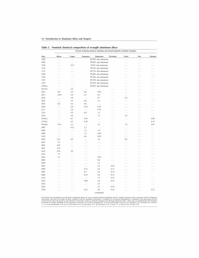
Table 2 Nominal chemical composition of wrought aluminum alloysPercent of alloying elements; aluminum and normal impurities constitute remainder
Alloy Silicon Copper Manganese Magnesium Chromium Nickel Zinc Titanium
1050 . . . . . . 99.50% min aluminum . . . . . . . . .
1060 . . . . . . 99.60% min aluminum . . . . . . . . .
1100 . . . 0.12 99.0% min aluminum . . . . . . . . .
1145 . . . . . . 99.45% min aluminum . . . . . . . . .
1175 . . . . . . 99.75% min aluminum . . . . . . . . .
1200 . . . . . . 99.00% min aluminum . . . . . . . . .
1230 . . . . . . 99.30% min aluminum . . . . . . . . .
1235 . . . . . . 99.35% min aluminum . . . . . . . . .
1345 . . . . . . 99.45% min aluminum . . . . . . . . .
1350(a) . . . . . . 99.50% min aluminum . . . . . . . . .
2011(b) . . . 5.5 . . . . . . . . . . . . . . . . . .
2014 0.8 4.4 0.8 0.50 . . . . . . . . . . . .
2017 0.50 4.0 0.7 0.6 . . . . . . . . . . . .
2018 . . . 4.0 . . . 0.7 . . . 2.0 . . . . . .
2024 . . . 4.4 0.6 1.5 . . . . . . . . . . . .
2025 0.8 4.4 0.8 . . . . . . . . . . . . . . .
2036 . . . 2.6 0.25 0.45 . . . . . . . . . . . .
2117 . . . 2.6 . . . 0.35 . . . . . . . . . . . .
2124 . . . 4.4 0.6 1.5 . . . . . . . . . . . .
2218 . . . 4.0 . . . 1.5 . . . 2.0 . . . . . .
2219(c) . . . 6.3 0.30 . . . . . . . . . . . . 0.06
2319(c) . . . 6.3 0.30 . . . . . . . . . . . . 0.15
2618(d) 0.18 2.3 . . . 1.6 . . . 1.0 . . . 0.07
3003 . . . 0.12 1.2 . . . . . . . . . . . . . . .
3004 . . . . . . 1.2 1.0 . . . . . . . . . . . .
3005 . . . . . . 1.2 0.40 . . . . . . . . . . . .
3105 . . . . . . 0.6 0.50 . . . . . . . . . . . .
4032 12.2 0.9 . . . 1.0 . . . 0.9 . . . . . .
4043 5.2 . . . . . . . . . . . . . . . . . . . . .
4045 10.0 . . . . . . . . . . . . . . . . . . . . .
4047 12.0 . . . . . . . . . . . . . . . . . . . . .
4145 10.0 4.0 . . . . . . . . . . . . . . . . . .
4343 7.5 . . . . . . . . . . . . . . . . . . . . .
4643 4.1 . . . . . . 0.20 . . . . . . . . . . . .
5005 . . . . . . . . . 0.8 . . . . . . . . . . . .
5050 . . . . . . . . . 1.4 . . . . . . . . . . . .
5052 . . . . . . . . . 2.5 0.25 . . . . . . . . .
5056 . . . . . . 0.12 5.0 0.12 . . . . . . . . .
5083 . . . . . . 0.7 4.4 0.15 . . . . . . . . .
5086 . . . . . . 0.45 4.0 0.15 . . . . . .
5154 . . . . . . . . . 3.5 0.25 . . . . . . . . .
5183 . . . . . . 0.08 4.8 0.15 . . . . . . . . .
5252 . . . . . . . . . 2.5 . . . . . . . . . . . .
5254 . . . . . . . . . 3.5 0.25 . . . . . . . . .
5356 . . . . . . 0.12 5.0 0.12 . . . . . . 0.13
(continued)
Listed herein are designations and chemical composition limits for some wrought unalloyed aluminum and for wrought aluminum alloys registered with the AluminumAssociation. This does not include all alloys registered with the Aluminum Association. A complete list of registered designations is contained in the Registration Recordof International Alloy Designations and Chemical Composition Limits for Wrought Aluminum and Wrought Aluminum Alloys. These lists are maintained by the TechnicalCommittee on Product Standards of The Aluminum Association. (a) Formerly designated EC. (b) Lead and bismuth, 0.40 each. (c) Vanadium, 0.10; zirconium 0.18. (d) Iron,1.1. (e) Lead and Bismuth, 0.55 each. (f) Zirconium, 0.14. (g) Zirconium, 0.12. (h) Zirconium, 0.18. (i) Iron, 0.7. (j) Boron, 0.02. (k) Iron, 0.35.
12 / Introduction to Aluminum Alloys and Tempers

The cast alloy designation system also has four digits, and the first digitspecifies the major alloying constituent(s) as shown in Table 3. However,a decimal point is used between the third and fourth digits to make clearthat these are designations used to identify alloys in the form of castingsor foundry ingot.
Table 2 (continued)Percent of alloying elements; aluminum and normal impurities constitute remainder
Alloy Silicon Copper Manganese Magnesium Chromium Nickel Zinc Titanium
5454 . . . . . . 0.08 2.7 0.12 . . . . . . . . .
5456 . . . . . . 0.08 5.1 0.12 . . . . . . . . .
5457 . . . . . . 0.30 1.0 . . . . . . . . . . . .
5554 . . . . . . 0.08 2.7 0.12 . . . . . . 0.12
5556 . . . . . . 0.08 5.1 0.12 . . . . . . 0.12
5652 . . . . . . . . . 2.5 0.25 . . . . . . . . .
5654 . . . . . . . . . 3.5 0.25 . . . . . . 0.10
5657 . . . . . . . . . 0.8 . . . . . . . . . . . .
6003 0.7 . . . . . . 1.2 . . . . . . . . . . . .
6005 0.8 . . . . . . 0.50 . . . . . . . . . . . .
6053 0.7 . . . . . . 1.2 0.25 . . . . . . . . .
6061 0.6 0.28 . . . 1.0 0.20 . . . . . . . . .
6063 0.40 . . . . . . 0.7 . . . . . . . . . . . .
6066 1.4 1.0 0.8 1.1 . . . . . . . . . . . .
6070 1.4 0.28 0.7 0.8 . . . . . . . . . . . .
6101 0.50 . . . . . . 0.6 . . . . . . . . . . . .
6105 0.8 . . . . . . 0.6 . . . . . . . . . . . .
6151 0.9 . . . . . . 0.6 0.25 . . . . . . . . .
6162 0.6 . . . . . . 0.9 . . . . . . . . . . . .
6201 0.7 . . . . . . 0.8 . . . . . . . . . . . .
6253 0.7 . . . . . . 1.2 0.25 . . . 2.0 . . .
6262(e) 0.6 0.28 . . . 1.0 0.09 . . . . . . . . .
6351 1.0 . . . 0.6 0.6 . . . . . . . . . . . .
6463 0.40 . . . . . . 0.7 . . . . . . . . . . . .
6951 0.35 0.28 . . . 0.6 . . . . . . . . . . . .
7005(f) . . . . . . 0.45 1.4 0.13 . . . 4.5 0.04
7008 . . . . . . . . . 1.0 0.18 . . . 5.0 . . .
7049 . . . 1.6 . . . 2.4 0.16 . . . 7.7 . . .
7050(g) . . . 2.3 . . . 2.2 . . . . . . 6.2 . . .
7072 . . . . . . . . . . . . . . . . . . 1.0 . . .
7075 . . . 1.6 . . . 2.5 0.23 . . . 5.6 . . .
7108(h) . . . . . . . . . 1.0 . . . . . . 5.0 . . .
7175 . . . 1.6 . . . 2.5 0.23 . . . 5.6 . . .
7178 . . . 2.0 . . . 2.8 0.23 . . . 6.8 . . .
7475 . . . 1.6 . . . 2.2 0.22 . . . 5.7 . . .
8017(i) . . . 0.15 . . . 0.03 . . . . . . . . . . . .
8030(j) . . . 0.22 . . . . . . . . . . . . . . . . . .
8176(i) 0.09 . . . . . . . . . . . . . . . . . . . . .
8177(k) . . . . . . . . . 0.08 . . . . . . . . . . . .
Listed herein are designations and chemical composition limits for some wrought unalloyed aluminum and for wrought aluminum alloys registered with the AluminumAssociation. This does not include all alloys registered with the Aluminum Association. A complete list of registered designations is contained in the Registration Recordof International Alloy Designations and Chemical Composition Limits for Wrought Aluminum and Wrought Aluminum Alloys. These lists are maintained by the TechnicalCommittee on Product Standards of The Aluminum Association. (a) Formerly designated EC. (b) Lead and bismuth, 0.40 each. (c) Vanadium, 0.10; zirconium 0.18. (d) Iron,1.1. (e) Lead and Bismuth, 0.55 each. (f) Zirconium, 0.14. (g) Zirconium, 0.12. (h) Zirconium, 0.18. (i) Iron, 0.7. (j) Boron, 0.02. (k) Iron, 0.35.
Aluminum Alloy and Temper Designation Systems of the Aluminum Association / 13

As for the wrought alloy designation system, the various digits of thecast alloy system convey information about the alloy:
O The first digit indicates the alloy group, as can be seen in Table 3. For2xx.x through 8xx.x alloys, the alloy group is determined by thealloying element present in the greatest mean percentage, except incases in which the composition being registered qualifies as a modifi-cation of a previously registered alloy. Note that in Table 3, the 6xx.xseries is shown last and for cast alloys is designated as the unusedseries.
O The second and third digits identify the specific aluminum alloy or, forthe aluminum 1xx.x series, indicate purity. If the greatest meanpercentage is common to more than one alloying element, the alloygroup is determined by the element that comes first in sequence. Forthe 1xx.x group, the second two of the four digits in the designationindicate the minimum aluminum percentage. These digits are the sameas the two digits to the right of the decimal point in the minimumaluminum percentage when expressed to the nearest 0.01%.
O The fourth digit indicates the product form: xxx.0 indicates castings,and xxx.1, for the most part, indicates ingot having limits for alloyingelements the same as or very similar to those for the alloy in the formof castings. A fourth digit of xxx.2 may be used to indicate that theingot has composition limits that differ from but fall within the xxx.1limits; this typically represents the use of tighter limits on certainimpurities to achieve specific properties in the finished cast productproduced from that ingot.
A letter before the numerical designation indicates a modification of theoriginal alloy or an impurity limit. These serial letters are assigned inalphabetical sequence starting with A, but omitting I, O, Q, and X, withX being reserved for experimental alloys. Note that explicit rules havebeen established for determining whether a proposed composition is amodification of an existing, or whether it is a new, alloy.
Table 4 presents the nominal compositions of a representative group ofcommercial aluminum casting alloys.
Table 3 Cast alloy designation systemAlloy Main alloying element
1xx.x Pure aluminum, 99.00% max
2xx.x Copper
3xx.x Silicon, with added copper and/or magnesium
4xx.x Silicon
5xx.x Magnesium
7xx.x Zinc
8xx.x Tin
9xx.x Other elements
6xx.x Unused series
14 / Introduction to Aluminum Alloys and Tempers
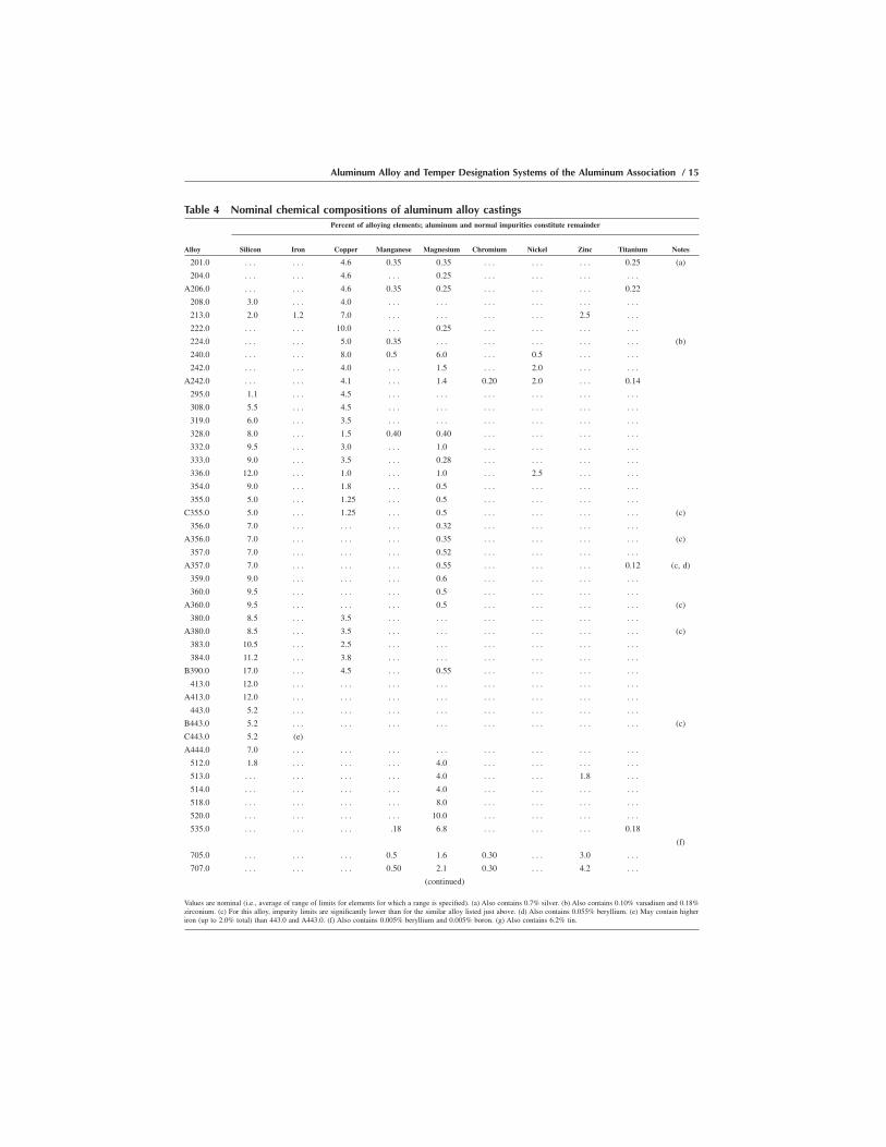
Table 4 Nominal chemical compositions of aluminum alloy castingsPercent of alloying elements; aluminum and normal impurities constitute remainder
Alloy Silicon Iron Copper Manganese Magnesium Chromium Nickel Zinc Titanium Notes
201.0 . . . . . . 4.6 0.35 0.35 . . . . . . . . . 0.25 (a)
204.0 . . . . . . 4.6 . . . 0.25 . . . . . . . . . . . .
A206.0 . . . . . . 4.6 0.35 0.25 . . . . . . . . . 0.22
208.0 3.0 . . . 4.0 . . . . . . . . . . . . . . . . . .
213.0 2.0 1.2 7.0 . . . . . . . . . . . . 2.5 . . .
222.0 . . . . . . 10.0 . . . 0.25 . . . . . . . . . . . .
224.0 . . . . . . 5.0 0.35 . . . . . . . . . . . . . . . (b)
240.0 . . . . . . 8.0 0.5 6.0 . . . 0.5 . . . . . .
242.0 . . . . . . 4.0 . . . 1.5 . . . 2.0 . . . . . .
A242.0 . . . . . . 4.1 . . . 1.4 0.20 2.0 . . . 0.14
295.0 1.1 . . . 4.5 . . . . . . . . . . . . . . . . . .
308.0 5.5 . . . 4.5 . . . . . . . . . . . . . . . . . .
319.0 6.0 . . . 3.5 . . . . . . . . . . . . . . . . . .
328.0 8.0 . . . 1.5 0.40 0.40 . . . . . . . . . . . .
332.0 9.5 . . . 3.0 . . . 1.0 . . . . . . . . . . . .
333.0 9.0 . . . 3.5 . . . 0.28 . . . . . . . . . . . .
336.0 12.0 . . . 1.0 . . . 1.0 . . . 2.5 . . . . . .
354.0 9.0 . . . 1.8 . . . 0.5 . . . . . . . . . . . .
355.0 5.0 . . . 1.25 . . . 0.5 . . . . . . . . . . . .
C355.0 5.0 . . . 1.25 . . . 0.5 . . . . . . . . . . . . (c)
356.0 7.0 . . . . . . . . . 0.32 . . . . . . . . . . . .
A356.0 7.0 . . . . . . . . . 0.35 . . . . . . . . . . . . (c)
357.0 7.0 . . . . . . . . . 0.52 . . . . . . . . . . . .
A357.0 7.0 . . . . . . . . . 0.55 . . . . . . . . . 0.12 (c, d)
359.0 9.0 . . . . . . . . . 0.6 . . . . . . . . . . . .
360.0 9.5 . . . . . . . . . 0.5 . . . . . . . . . . . .
A360.0 9.5 . . . . . . . . . 0.5 . . . . . . . . . . . . (c)
380.0 8.5 . . . 3.5 . . . . . . . . . . . . . . . . . .
A380.0 8.5 . . . 3.5 . . . . . . . . . . . . . . . . . . (c)
383.0 10.5 . . . 2.5 . . . . . . . . . . . . . . . . . .
384.0 11.2 . . . 3.8 . . . . . . . . . . . . . . . . . .
B390.0 17.0 . . . 4.5 . . . 0.55 . . . . . . . . . . . .
413.0 12.0 . . . . . . . . . . . . . . . . . . . . . . . .
A413.0 12.0 . . . . . . . . . . . . . . . . . . . . . . . .
443.0 5.2 . . . . . . . . . . . . . . . . . . . . . . . .
B443.0 5.2 . . . . . . . . . . . . . . . . . . . . . . . . (c)
C443.0 5.2 (e)
A444.0 7.0 . . . . . . . . . . . . . . . . . . . . . . . .
512.0 1.8 . . . . . . . . . 4.0 . . . . . . . . . . . .
513.0 . . . . . . . . . . . . 4.0 . . . . . . 1.8 . . .
514.0 . . . . . . . . . . . . 4.0 . . . . . . . . . . . .
518.0 . . . . . . . . . . . . 8.0 . . . . . . . . . . . .
520.0 . . . . . . . . . . . . 10.0 . . . . . . . . . . . .
535.0 . . . . . . . . . .18 6.8 . . . . . . . . . 0.18
(f)
705.0 . . . . . . . . . 0.5 1.6 0.30 . . . 3.0 . . .
707.0 . . . . . . . . . 0.50 2.1 0.30 . . . 4.2 . . .
(continued)
Values are nominal (i.e., average of range of limits for elements for which a range is specified). (a) Also contains 0.7% silver. (b) Also contains 0.10% vanadium and 0.18%zirconium. (c) For this alloy, impurity limits are significantly lower than for the similar alloy listed just above. (d) Also contains 0.055% beryllium. (e) May contain higheriron (up to 2.0% total) than 443.0 and A443.0. (f) Also contains 0.005% beryllium and 0.005% boron. (g) Also contains 6.2% tin.
Aluminum Alloy and Temper Designation Systems of the Aluminum Association / 15

Designations for Experimental Aluminum Alloys
Experimental alloys of either the wrought or cast aluminum series areindicated with the addition of the prefix X. This prefix is dropped whenthe alloy is no longer experimental. However, during development andbefore an alloy is designated as experimental, a new composition may beidentified by a serial number assigned by the originating organization.Use of the serial number is discontinued when the composition isregistered with the Aluminum Association and the ANSI H35.1 designa-tion is assigned.
Aluminum Alloy Temper Designation System
Basic Temper DesignationsThe temper designation is always presented immediately following the
alloy designation with a hyphen between the designation and the temper(e.g., 2014-T6).
The first character in the temper designation is a capital letter indicatingthe general class of treatment. The designations are defined and describedas follows:
O F, as fabricated: Applies to wrought or cast products made by shapingprocesses in which there is no special control over thermal conditionsor strain-hardening processes employed to achieve specific properties.For wrought alloys there are no mechanical property limits associatedwith this temper, although for cast alloys there generally are.
O O, annealed: Applies to wrought products that are annealed to obtainthe lower strength temper, usually to increase subsequent workability.The O applies to cast products that are annealed to improve ductility
Table 4 (continued)Percent of alloying elements; aluminum and normal impurities constitute remainder
Alloy Silicon Iron Copper Manganese Magnesium Chromium Nickel Zinc Titanium Notes
710.0 . . . . . . 0.50 . . . 0.7 . . . . . . 6.5 . . .
711.0 . . . 1.0 0.50 . . . 0.35 . . . . . . 6.5 . . .
712.0 . . . . . . . . . . . . 0.58 0.50 . . . 6.0 0.20
713.0 . . . . . . 0.7 . . . 0.35 . . . . . . 7.5 . . .
771.0 . . . . . . . . . . . . 0.9 0.40 . . . 7.0 0.15
850.0 . . . . . . 1.0 . . . . . . . . . 1.0 . . . . . . (g)
851.0 2.5 . . . 1.0 . . . . . . . . . 0.50 . . . . . . (g)
852.0 . . . . . . 2.0 . . . 0.75 . . . 1.2 . . . . . . (g)
Values are nominal (i.e., average of range of limits for elements for which a range is specified). (a) Also contains 0.7% silver. (b) Also contains 0.10% vanadium and 0.18%zirconium. (c) For this alloy, impurity limits are significantly lower than for the similar alloy listed just above. (d) Also contains 0.055% beryllium. (e) May contain higheriron (up to 2.0% total) than 443.0 and A443.0. (f) Also contains 0.005% beryllium and 0.005% boron. (g) Also contains 6.2% tin.
16 / Introduction to Aluminum Alloys and Tempers

and dimensional stability and may be followed by a digit other thanzero.
O H, strain hardened: Applies to products that have their strengthincreased by strain hardening. They may or may not have supplemen-tary thermal treatments to produce some reduction in strength. The His always followed by two or more digits.
O W, solution heat treated: Applies only to alloys that age spontaneouslyafter solution heat treating. This designation is specific only whendigits are used in combination with W to indicate the period of naturalaging, for example, W 1⁄2 hr.
O T, thermally treated to produce stable tempers other than F, O, or H:Applies to products that are thermally treated, with or withoutsupplementary strain hardening, to produce stable tempers. The T isalways followed by one or more digits.
Subdivisions of the Basic TempersThe temper designation system is based on sequences of basic treat-
ments used to produce different tempers and their variations. Subdivisionsof the basic tempers, discussed next, are indicated by one or more digits(descriptor digits) following the letter.
Subdivisions of the Basic H Tempers. The first number(s) followingthe letter designation indicates the specific combination of basic opera-tions:
O H1, strain hardened only: Applies to products that have been strainhardened to obtain a desired level of strength without a supplementarythermal treatment. The number following H1 indicates degree of strainhardening.
O H2, strain hardened and partially annealed: Applies to products thathave been strain hardened more than the desired final amount, and theirstrength is reduced to the desired level by partial annealing. Thenumber added to H2 indicates the degree of strain hardening remainingafter partial annealing.
O H3, strain hardened and stabilized: Applies to products that have beenstrain hardened and then stabilized either by a low temperature thermaltreatment, or as a result of heat introduced during fabrication of theproduct. Stabilization usually improves ductility. The H3 temper isused only for those alloys that will gradually age soften at roomtemperature if they are not stabilized. The number added to H3indicates the degree of strain hardening remaining after stabilization.
O H4, strain hardened and lacquered or painted: Applies to products thatare strain hardened and that have been subjected to heat duringsubsequent painting or lacquering operations. The number added to H4indicates the amount of strain hardening left after painting or lacquer-ing.
Aluminum Alloy and Temper Designation Systems of the Aluminum Association / 17

Adding Additional Digits: H Temper. A digit following H1, H2, H3,or H4 indicates the degree of strain hardening as identified or indicated bythe minimum value for tensile strength:
O The hardest temper normally produced is indicated by adding thenumeral 8 (i.e., HX8).
O A degree of cold work equal to approximately one-half that for theHX8 temper is indicated by the HX4 temper, and so on.
O For a degree of cold work halfway between the O temper and the HX4temper, the HX2 temper is used.
O For a degree of cold work halfway between HX4 and HX8, the HX6temper is used.
O The numbers 1, 3, 5, and 7, similarly, designate tempers intermediatebetween those just listed.
O The numeral 9 is used to indicate tempers that exceed those of HX8 by14 MPa (2 ksi) or more.
Table 5 indicates gains in the tensile strength of wrought alloys in theannealed temper when they are treated to the HX8 temper.
Several three-digit H tempers also have been standardized. For allstrain-hardenable alloys, the following three-digit designations are rec-ognized:
O HX11: Applies to products that incur sufficient strain hardening afterthe final anneal such that they fail to qualify as annealed, but not somuch or so consistent an amount of strain that they qualify as HX1.
O H112: Applies to products that may acquire some temper from workingat an elevated temperature and for which there are mechanical propertylimits.
Other recognized three-digit H tempers apply to types of sheet, as shownin Table 6.
Table 5 Tensile strengths of HX8 tempersMinimum tensile strengthin annealed temper, ksi
Increase in tensile strengthto HX8 temper, ksi
Up to 6 8
7–9 9
10–12 10
13–15 11
16–18 12
19–24 13
25–20 14
31–36 15
37–42 16
43 and over 17
18 / Introduction to Aluminum Alloys and Tempers
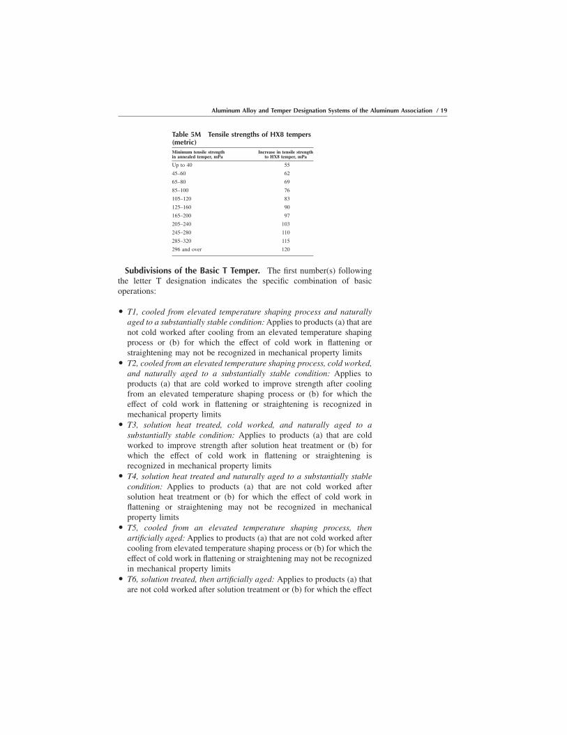
Subdivisions of the Basic T Temper. The first number(s) followingthe letter T designation indicates the specific combination of basicoperations:
O T1, cooled from elevated temperature shaping process and naturallyaged to a substantially stable condition: Applies to products (a) that arenot cold worked after cooling from an elevated temperature shapingprocess or (b) for which the effect of cold work in flattening orstraightening may not be recognized in mechanical property limits
O T2, cooled from an elevated temperature shaping process, cold worked,and naturally aged to a substantially stable condition: Applies toproducts (a) that are cold worked to improve strength after coolingfrom an elevated temperature shaping process or (b) for which theeffect of cold work in flattening or straightening is recognized inmechanical property limits
O T3, solution heat treated, cold worked, and naturally aged to asubstantially stable condition: Applies to products (a) that are coldworked to improve strength after solution heat treatment or (b) forwhich the effect of cold work in flattening or straightening isrecognized in mechanical property limits
O T4, solution heat treated and naturally aged to a substantially stablecondition: Applies to products (a) that are not cold worked aftersolution heat treatment or (b) for which the effect of cold work inflattening or straightening may not be recognized in mechanicalproperty limits
O T5, cooled from an elevated temperature shaping process, thenartificially aged: Applies to products (a) that are not cold worked aftercooling from elevated temperature shaping process or (b) for which theeffect of cold work in flattening or straightening may not be recognizedin mechanical property limits
O T6, solution treated, then artificially aged: Applies to products (a) thatare not cold worked after solution treatment or (b) for which the effect
Table 5M Tensile strengths of HX8 tempers(metric)Minimum tensile strengthin annealed temper, mPa
Increase in tensile strengthto HX8 temper, mPa
Up to 40 55
45–60 62
65–80 69
85–100 76
105–120 83
125–160 90
165–200 97
205–240 103
245–280 110
285–320 115
296 and over 120
Aluminum Alloy and Temper Designation Systems of the Aluminum Association / 19

of cold work in flattening or straightening may not be recognized inmechanical property limits
O T7, solution heat treated and overaged/stabilized: Applies to (a)wrought products that are artificially aged after solution heat treating toincrease their strength beyond the maximum value achievable toprovide control of some significant property or characteristic or (b) castproducts that are artificially aged after solution treatment to providestability in dimensions and in strength
O T8, solution heat treated, cold worked, then artificially aged: Appliesto products (a) that are cold worked to improve strength or (b) forwhich the effect of cold work in flattening and straightening isrecognized in mechanical property limits
O T9, solution heat treated, artificially aged, then cold worked: Appliesto products that are cold worked to improve strength
O T10, cooled from an elevated temperature shaping process, coldworked, then artificially aged: Applies to products (a) that are coldworked to improve strength or (b) for which the effect of cold work inflattening or straightening is recognized in mechanical property limits
In all of the T-type temper definitions just described, solution heattreatment is achieved by:
O Heating cast or wrought shaped products to a suitable temperatureO Holding them at that temperature long enough to allow constituents to
enter into solid solutionO Cooling them rapidly enough to hold the constituents in solution to
take advantage of subsequent precipitation and the associated strength-ening (i.e., precipitation hardening)
Adding Additional Digits: T Temper. Additional digits, the first ofwhich shall not be zero, may be added to designations T1 through T10 toindicate a variation in treatment that significantly alters the productcharacteristics that are or would be obtained using the basic treatment.The specific additional digits shown in Table 7 have been assigned forstress-relieved tempers of wrought products. The special T-temper desig-
Table 6 Tempers for aluminum pattern sheetPattern or embossed sheet Fabricated from
H114 O temper
H124, H224, H324 H11, H21, H31 temper, respectively
H134, H234, H334 H12, H22, H32 temper, respectively
H144, H244, H344 H13, H23, H33 temper, respectively
H154, H254, H354 H14, H24, H34 temper, respectively
H164, H264, H364 H15, H25, H35 temper, respectively
H174, H274, H374 H16, H26, H36 temper, respectively
H184, H284, H384 H17, H27, H37 temper, respectively
H194, H294, H394 H18, H28, H38 temper, respectively
H195, H295, H395 H19, H29, H39 temper, respectively
20 / Introduction to Aluminum Alloys and Tempers
nations listed in Table 8 have been assigned for wrought aluminumproducts from which test materials are taken and heat treated todemonstrate response to heat treatment of the product as a whole.
Assigned O-Temper Variations. The following temper designationhas been assigned for wrought products that are high-temperatureannealed to accentuate ultrasonic response and to provide dimensionalstability:
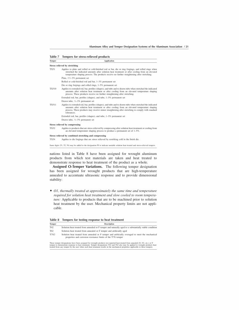
O O1, thermally treated at approximately the same time and temperaturerequired for solution heat treatment and slow cooled to room tempera-ture: Applicable to products that are to be machined prior to solutionheat treatment by the user. Mechanical property limits are not appli-cable.
Table 7 Tempers for stress-relieved productsTemper Application
Stress relieved by stretching
TX51 Applies to plate and rolled or cold-finished rod or bar, die or ring forgings, and rolled rings whenstretched the indicated amounts after solution heat treatment or after cooling from an elevatedtemperature shaping process. The products receive no further straightening after stretching.
Plate, 11⁄2–3% permanent set
Rolled or cold-finished rod and bar, 1–3% permanent set
Die or ring forgings and rolled rings, 1–5% permanent set
TX510 Applies to extruded rod, bar, profiles (shapes), and tube and to drawn tube when stretched the indicatedamounts after solution heat treatment or after cooling from an elevated temperature shapingprocess. These products receive no further straightening after stretching.
Extruded rod, bar, profiles (shapes), and tube, 1–3% permanent set
Drawn tube, 1⁄2–3% permanent set
TX511 Applies to extruded rod, bar, profiles (shapes), and tube and to drawn tube when stretched the indicatedamounts after solution heat treatment or after cooling from an elevated temperature shapingprocess. These products may receive minor straightening after stretching to comply with standardtolerances.
Extruded rod, bar, profiles (shapes), and tube, 1–3% permanent set
Drawn tube, 1⁄2–3% permanent set
Stress relieved by compressing
TX52 Applies to products that are stress relieved by compressing after solution heat treatment or cooling froman elevated temperature shaping process to produce a permanent set of 1–5%.
Stress relieved by combined stretching and compressing
TX54 Applies to die forgings that are stress relieved by restriking cold in the finish die.
Same digits (51, 52, 54) may be added to the designation W to indicate unstable solution heat treated and stress-relieved tempers.
Table 8 Tempers for testing response to heat treatmentTemper Description
T42 Solution heat treated from annealed or F temper and naturally aged to a substantially stable condition
T62 Solution heat treated from annealed or F temper and artificially aged
T7X2 Solution heat treated from annealed or F temper and artificially overaged to meet the mechanicalproperties and corrosion resistance limits of the T7X temper
These temper designations have been assigned for wrought products test material heat-treated from annealed (O, O1, etc.) or Ftemper to demonstrate response to heat treatment. Temper designations T42 and T62 also may be applied to wrought products heattreated from any temper by the user when such heat treatment results in the mechanical properties applicable to these tempers.
Aluminum Alloy and Temper Designation Systems of the Aluminum Association / 21

Note: As the O temper is not part of the strain-hardened (H) series,variations of O temper shall not apply to products that are strain hardenedafter annealing and in which the effect of strain hardening is recognizedin the mechanical properties or other characteristics.
Summary
This completes an overview of the Aluminum Association Alloy andTemper Designation Systems in the terms described in AluminumStandards and Data and in ANSI H35.1. In the chapters that follow, wewill look at the systems in more detail, discuss the meanings of some ofthe variations, and provide illustrations of the usage of the systems. Withthis information, heat treaters, fabricators, and end users of aluminumproducts should be able to better understand the designations and, hence,the practices used in their particular situations.
For more detailed information on any of the discussion presented in thischapter, the reader is referred directly to the master sources (publicationinformation can be found in Chapter 8, “Selected References”):
O Aluminum Standards and Data (English/engineering and metric edi-tions)
O American National Standard Alloy and Temper Designation Systemsfor Aluminum
O Standards for Aluminum Sand and Permanent Mold Casting
22 / Introduction to Aluminum Alloys and Tempers

CHAPTER 3Understanding Wrought
and Cast AluminumAlloys Designations
THE WROUGHT ALLOY DESIGNATION SYSTEM consists of fournumerical digits, sometimes preceded by a capital letter as indicated inChapter 2. The first digit indicates the principal alloying elements, asdescribed in this chapter in the section “Principal Alloying Elements” andTable 1; the second digit is the variation of that alloy; and the last twodigits represent the specific alloy designation.
The Wrought Alloy Series
How the System is AppliedThe First Digit. Assignment of the first digit of the designation of a
new alloy is fairly straightforward; few judgment decisions are neededunless there are equal amounts of two or more alloys. In the latter case,specific guidance has been provided by the developers of the alloydesignation system that the choice of alloy series assigned shall be in theorder of copper (Cu), manganese (Mn), silicon (Si), magnesium (Mg),magnesium silicide (Mg2Si), and zinc (Zn). Thus, if a new alloy has equalamounts of manganese and zinc, it will be assigned to the 3xxx series. Insuch cases, the 6xxx series requires the most judgment because alloys thathave more silicon than magnesium, but significant quantities of both, arelikely to be placed in the 6xxx series rather than the 4xxx series inestablishing properties and characteristics due to the predominance of themagnesium and silicon combination. Thus, for example, alloys such as6005, 6066, and 6351, all have significantly more silicon than magnesiumor other elements, but find themselves in the Mg2Si series.
Introduction to Aluminum Alloys and TempersJ. Gilbert Kaufman, p23-37 DOI:10.1361/iaat2000p023
Copyright © 2000 ASM International® All rights reserved. www.asminternational.org

The Second Digit. Assignment of the second digit of the alloydesignation is related to the variations in a specific alloy, in many cases,tightening of controls on one or more impurities to achieve specificproperties. If the second digit is 0, it generally indicates that the aluminummaking up the bulk of the alloy is commercially pure aluminum havingnaturally occurring impurity levels. When the second digit is an integer 1to 9, it indicates that some special control has been placed on the impuritylevels of that variation, or that the range for one of the major alloyelements has been shaded one way or the other to achieve certainperformance. However, the sequence has no significance in the compo-sition variation; the digits are assigned sequentially as the situationsoccur, and the sequence indicates chronology more than level of control.
An example of the application of these principles is the alloy set 7075,7175, 7275, 7375, and 7475. The original alloy was 7075 with commer-cial quality aluminum; when added fracture toughness was needed,controls on various impurities, notably iron and silicon led to the othervariations, of which 7175 and 7475 remain active alloys known for theirsuperior toughness.
The Third and Fourth Digits. As noted earlier, the last two digits inthe 1xxx series indicate the purity level in terms of the first two digits afterthe 99.XX% purity of the aluminum used in preparing that composition.Thus, for example, the designation 1060 indicates 99.60% minimumaluminum in that composition. In the remaining 2xxx to 8xxx series, thelast two digits have no special significance. They serve only to identifythe specific individual alloys and mean nothing in terms of the sequencein which the alloys were developed or registered. Historically, for theolder alloys, those digits came from the earlier designations (e.g., 2024was 24S before 1950). More recently, it has been the tradition thatdevelopers of new alloys ask for specific designations, sometimes basedon proximity of application to other alloys of the same series or becausethey judge them easy to remember or such. Alloy 2020, now inactive, isan example of the latter. If the developer asks for a specific number whenfiling for registration, the Aluminum Association Product StandardsCommittee, which oversees the system, is likely to agree to the requestif no confusion would result. However, if no designation is requested,the committee would likely take the lowest used number in the sequence1 to 99.
The alloy designation system also calls for the use of capital letters infront of the four-digit numerical:
O Experimental alloys—X: Early in the development of aluminum alloys,when such development has moved beyond single-company in-housetrials, and the alloys are ready for customer trials and/or perhapsmulticompany production but are still not sufficiently well understoodor documented to become standard alloys, the alloys may be registered,
24 / Introduction to Aluminum Alloys and Tempers
but an X is added to the designation. A historical example was the useof X2020, when the first of the lithium-bearing alloys was put forth inthe 1960s. That designation was employed for about ten years beforethe further use of the alloy was deemed inappropriate and itsapplication was discontinued. Another example is X7050, from whichthe X was removed once the broad application of the alloy wasconsidered appropriate and the properties and standards were welldefined.
O Variations—A, B, etc.: Under certain situations when minor variationsin alloy compositions are introduced, such variation sometimes isnoted with the addition of a capital letter behind the original four-number designation, rather than a change in the second digit. The onlycurrent example of the application of this procedure in commercialpractice is 6005A—a modification of alloy 6005. In general, thepractice is to reflect such variations with the second digit as notedearlier in this chapter.
Principal Alloying ElementsAs indicated in Chapter 2 and in the previous discussion, the most
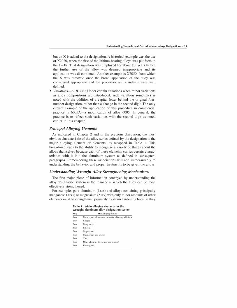
obvious characteristic of the alloy series defined by the designation is themajor alloying element or elements, as recapped in Table 1. Thisbreakdown leads to the ability to recognize a variety of things about thealloys themselves because each of these elements carries certain charac-teristics with it into the aluminum system as defined in subsequentparagraphs. Remembering these associations will add immeasurably tounderstanding the behavior and proper treatments to be given the alloys.
Understanding Wrought Alloy Strengthening MechanismsThe first major piece of information conveyed by understanding the
alloy designation system is the manner in which the alloy can be mosteffectively strengthened.
For example, pure aluminum (1xxx) and alloys containing principallymanganese (3xxx) or magnesium (5xxx) with only minor amounts of otherelements must be strengthened primarily by strain hardening because they
Table 1 Main alloying elements in thewrought aluminum alloy designation systemAlloy Main alloying element
1xxx Mostly pure aluminum; no major alloying additions
2xxx Copper
3xxx Manganese
4xxx Silicon
5xxx Magnesium
6xxx Magnesium and silicon
7xxx Zinc
8xxx Other elements (e.g., iron and silicon)
9xxx Unassigned
Understanding Wrought and Cast Aluminum Alloys Designations / 25
do not respond to solution heat treatment. Pure aluminum has noappreciable amounts of any elements that can go into solution to providesolution strengthening or precipitation hardening. And elements such asmagnesium, silicon, and manganese, while they are soluble to somedegree in aluminum and provide modest solution strengthening, do notprovide for an appreciable amount of the more significant precipitationhardening. Thus, for pure aluminum and the 3xxx and 5xxx alloys, coldrolling, stretching, or drawing, or some combination of these, are theprincipal means of strengthening.
On the other hand, elements such as copper (2xxx series), zinc (7xxxseries), and magnesium in combination with silicon as Mg2Si (6xxxseries) do go into solution to an appreciable degree and provide theopportunity for appreciable precipitation hardening. Thus, solution heattreatment (a high temperature holding to permit the elements to go intosolution), followed by a sufficiently rapid quench to keep the elements insolution, and then either natural aging (i.e., at room temperature) orartificial aging (holding in a furnace at a moderately elevated tempera-ture) for precipitation hardening are most often used. The result is thatalloy series containing copper (2xxx), magnesium plus silicon (6xxx), orzinc (7xxx) are the higher-strength series.
The 4xxx series is somewhat unique in that silicon alone does notprovide much heat treating advantage, so most alloys in this series areconsidered non-heat-treatable. However, in some 4xxx alloys the silicon ispresent with sufficient amounts of other elements such as magnesium thatheat treatment is effective; alloy 4032 is an example. The situation issimilar for the 8xxx series; some alloys such as 8017 and 8040 with onlysmall amounts of alloying element are non-heat-treatable, while thosesuch as 8090, with a significant amount of copper are.
Understanding Wrought Alloy Advantages and Limitations
In addition to being indicative of specific strengthening mechanisms,the major alloying elements also indicate several things about basicbehavioral or performance characteristics of the alloys. It is helpful to asecondary fabricator, heat treater, or user of the various alloys to beknowledgeable about these as well. The following example characteristicsmay be noted.
1xxx, Pure Aluminum. The compositions in this group have relativelylow strength, even when strain hardened; however, they have extremelyhigh ductility and formability and so may be readily worked or formed.The 1xxx series aluminums also have exceptionally high electricalconductivity and resistance to all types of corrosive environments andmay be readily joined by a number of commercial processes.
2xxx, Copper. As the principal alloying element in this series, copperprovides relatively high strength because it provides solution strengthen-ing and the ability to precipitation harden. Many commercial aluminum
26 / Introduction to Aluminum Alloys and Tempers

alloys contain copper as the principal alloying constituent in concentra-tions from 1 to 10%. Because these alloys naturally age at roomtemperature, it is advantageous to do any required working or forming ofthe metal soon after quenching from solution heat treatment. If a delay isneeded, it may be desirable to cool them until the mechanical work canbe performed.
In the fully hardened (age-hardened) condition, the ductility of 2xxxalloys is generally lower than for some other alloys (except in specialvariations that are discussed later), and their resistance to atmosphericcorrosion is not as good as that of pure aluminum or most non-heat-treatable alloys.
Unless given special treatments, 2xxx alloys in the T3 and T4 conditionsmay be susceptible to stress-corrosion cracking (SCC) when stressed inthe short-transverse direction (i.e., normal to the principal plane of grainflow). Precipitation hardening improves resistance to SCC but reducesductility and toughness.
Most aluminum-copper alloys are not readily welded by commercialprocesses, but a few alloys such as 2219 and 2195 have been developedespecially for applications requiring welding.
3xxx, Manganese. Manganese provides only modest strength increaseeven when strain hardened but relatively high formability and ductility,and very high resistance to corrosion in almost all environments. Alloysof the 3xxx series are readily weldable and are among the best for brazingand soldering applications.
Commercial aluminum-manganese alloys contain up to 1.2% manga-nese, but it is appropriate to note that manganese is commonly employedas a supplementary alloying constituent in alloys of the other series toenhance strength.
4xxx, Silicon. There are two types of silicon-bearing aluminum alloys:those with silicon alone, which are not very strong but provide excellentflow and finishing characteristics, and those that also include copperand/or magnesium as well as silicon and so gain strength by solution heattreatment and aging.
The 4xxx alloys are not highly resistant to atmospheric corrosion andtend to “gray” with time in humid environments. Interestingly, thischaracteristic is used to advantage with finishing techniques such asanodizing to obtain a variety of rich gray shades.
Because silicon adds to their “flow” characteristics during working,some 4xxx alloys (e.g., 4032) are used for complex or finely detailedforgings such as pistons. The 4xxx alloys are readily welded and, in fact,include some of the mostly widely used weld filler alloys, another resultof their high fluidity.
5xxx, Magnesium. Magnesium additions to aluminum provide amongthe highest strength non-heat-treatable alloys. These alloys also areexceptionally tough, absorbing lots of energy during fracture, and so
Understanding Wrought and Cast Aluminum Alloys Designations / 27

can be used in critical applications where superior toughness is vital.Alloys of the 5xxx series are readily welded by commercial procedures.
Generally, the 5xxx alloys also have excellent resistance to atmosphericand seawater corrosion to the point that they may be used in severemarine environments (as described in more detail in Chapter 6). However,alloys with more than 3% Mg are not recommended for service in whichsignificant exposure to high temperature may be encountered becausesome sensitization to SCC may develop. For these types of applications,alloys such as 5052, 5454, and 5754 containing less magnesium arerecommended.
6xxx, Magnesium Plus Silicon. With both magnesium and siliconpresent, aluminum forms a quasi-binary section with the Mg2Si phase ofthe magnesium-silicon system, which in turn provides excellent precipi-tation-hardening capability. This results in modestly higher strengths thanpossible with non-heat-treatable alloys, combined with generally excel-lent corrosion resistance.
Alloys of the 6xxx type are among the easiest of aluminum alloys toextrude, and are thus widely used for complex (e.g., multihollow orfinned) shapes produced in this manner. In addition, they are readilyjoined by almost all commercial processes.
As with the 2xxx series, some natural aging begins immediately aftersolution heat treatment, so forming operations should be scheduled soonafter the material is quenched.
7xxx, Zinc. Zinc-bearing aluminum alloys, especially when combinedwith copper and magnesium, provide the highest strengths of anycommercial series.
As a group, these alloys possess relatively poorer atmospheric corrosionresistance compared with other aluminum alloys and, except for thespecial versions described later, are less tough and more susceptible tostress-corrosion cracking under short-transverse stressing. Special treat-ments have been developed to deal with these characteristics and areespecially important when the alloys would be subjected to high short-transverse stresses in service (as described in the following paragraphs).
As with the 2xxx and 6xxx series, 7xxx alloys naturally age followingheat treatment, so scheduling of any intended forming operations isessential.
Other Characteristics Related to Principal Alloying Element
As noted earlier, knowledge of the alloy designation system alsoprovides some information about the properties and characteristics of thealloys. Two notable examples are density and modulus of elasticity:
O Density: The density of each aluminum alloy is influenced by thedensity of each of the individual alloying elements, most especially bythe major alloying element indicated by the first number of the
28 / Introduction to Aluminum Alloys and Tempers
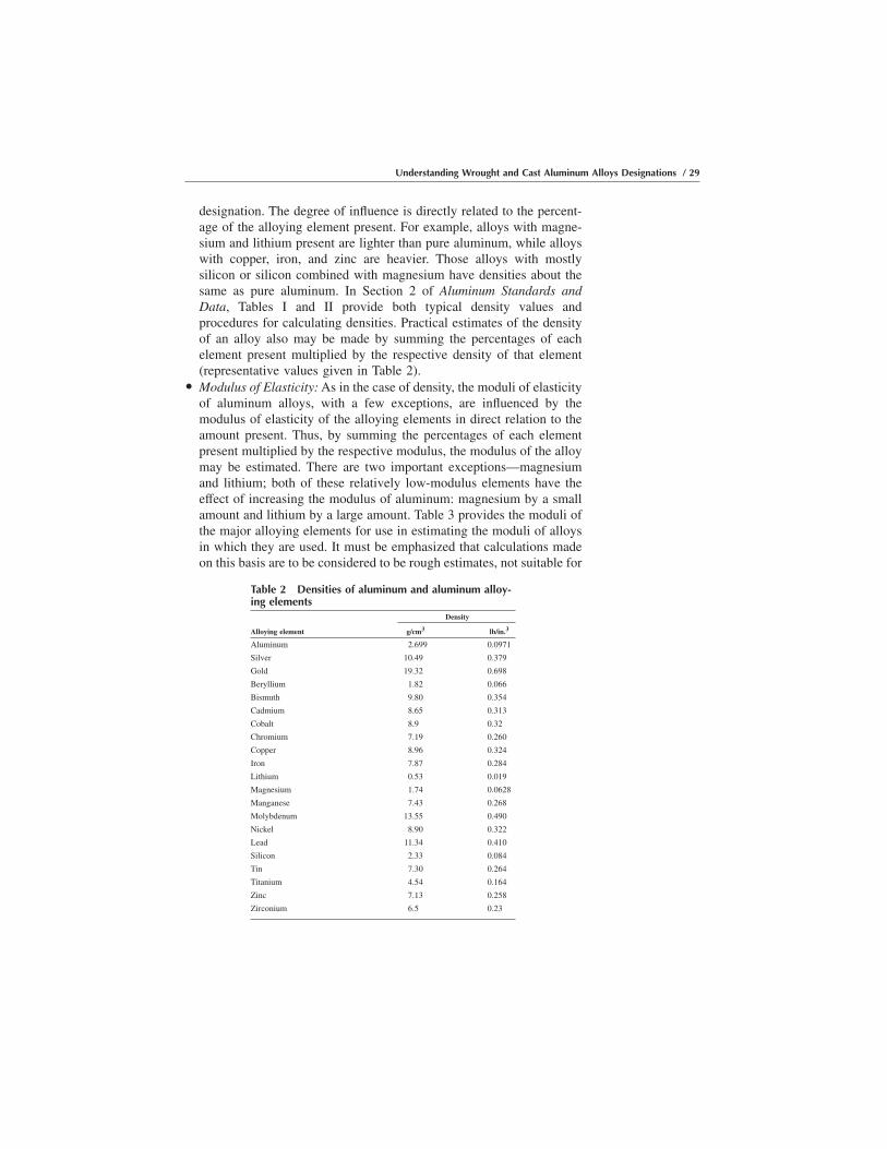
designation. The degree of influence is directly related to the percent-age of the alloying element present. For example, alloys with magne-sium and lithium present are lighter than pure aluminum, while alloyswith copper, iron, and zinc are heavier. Those alloys with mostlysilicon or silicon combined with magnesium have densities about thesame as pure aluminum. In Section 2 of Aluminum Standards andData, Tables I and II provide both typical density values andprocedures for calculating densities. Practical estimates of the densityof an alloy also may be made by summing the percentages of eachelement present multiplied by the respective density of that element(representative values given in Table 2).
O Modulus of Elasticity: As in the case of density, the moduli of elasticityof aluminum alloys, with a few exceptions, are influenced by themodulus of elasticity of the alloying elements in direct relation to theamount present. Thus, by summing the percentages of each elementpresent multiplied by the respective modulus, the modulus of the alloymay be estimated. There are two important exceptions—magnesiumand lithium; both of these relatively low-modulus elements have theeffect of increasing the modulus of aluminum: magnesium by a smallamount and lithium by a large amount. Table 3 provides the moduli ofthe major alloying elements for use in estimating the moduli of alloysin which they are used. It must be emphasized that calculations madeon this basis are to be considered to be rough estimates, not suitable for
Table 2 Densities of aluminum and aluminum alloy-ing elements
Density
Alloying element g/cm3 lb/in.3
Aluminum 2.699 0.0971
Silver 10.49 0.379
Gold 19.32 0.698
Beryllium 1.82 0.066
Bismuth 9.80 0.354
Cadmium 8.65 0.313
Cobalt 8.9 0.32
Chromium 7.19 0.260
Copper 8.96 0.324
Iron 7.87 0.284
Lithium 0.53 0.019
Magnesium 1.74 0.0628
Manganese 7.43 0.268
Molybdenum 13.55 0.490
Nickel 8.90 0.322
Lead 11.34 0.410
Silicon 2.33 0.084
Tin 7.30 0.264
Titanium 4.54 0.164
Zinc 7.13 0.258
Zirconium 6.5 0.23
Understanding Wrought and Cast Aluminum Alloys Designations / 29
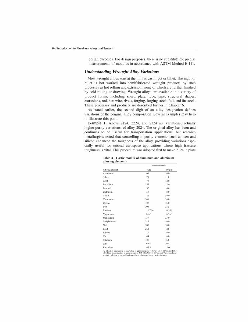
design purposes. For design purposes, there is no substitute for precisemeasurements of modulus in accordance with ASTM Method E 111.
Understanding Wrought Alloy Variations
Most wrought alloys start at the mill as cast ingot or billet. The ingot orbillet is hot worked into semifabricated wrought products by suchprocesses as hot rolling and extrusion, some of which are further finishedby cold rolling or drawing. Wrought alloys are available in a variety ofproduct forms, including sheet, plate, tube, pipe, structural shapes,extrusions, rod, bar, wire, rivets, forging, forging stock, foil, and fin stock.These processes and products are described further in Chapter 6.
As stated earlier, the second digit of an alloy designation definesvariations of the original alloy composition. Several examples may helpto illustrate this point.
Example 1. Alloys 2124, 2224, and 2324 are variations, actuallyhigher-purity variations, of alloy 2024. The original alloy has been andcontinues to be useful for transportation applications, but researchmetallurgists noted that controlling impurity elements such as iron andsilicon enhanced the toughness of the alloy, providing variations espe-cially useful for critical aerospace applications where high fracturetoughness is vital. This procedure was adopted first to make 2124, a plate
Table 3 Elastic moduli of aluminum and aluminumalloying elements
Elastic modulus
Alloying element GPa 106 psi
Aluminum 69 10.0
Silver 71 11.0
Gold 78 12.0
Beryllium 255 37.0
Bismuth 32 4.6
Cadmium 55 8.0
Cobalt 21 30.0
Chromium 248 36.0
Copper 128 16.0
Iron 208 28.5
Lithium 0.7(b) 0.1(b)
Magnesium 44(a) 6.5(a)
Manganese 159 23.0
Molybdenum 325 50.0
Nickel 207 30.0
Lead 261 2.6
Silicon 110 16.0
Tin 44 6.0
Titanium 120 16.8
Zinc 69(c) 10(c)
Zirconium 49.3 11.0
(a) Effect of magnesium is equivalent to approximately 75 GPa/11.0 � 106psi. (b) Effectof lithium is equivalent to approximately 207 GPa/30.0 � 106psi. (c) The modulus ofelasticity of zinc is not well defined; these values are lower-limit estimates.
30 / Introduction to Aluminum Alloys and Tempers

alloy with all the advantages of 2024 but substantially higher elongationand toughness, especially in the short transverse direction. The processwas adopted subsequently to create 2324, an alloy for extrusions withsimilar attributes. Some special processing also may be required for suchalloys.
Example 2. Alloys 7175 and 7475 are modifications of alloy 7075.Both 7175 and 7475 alloys have the same major alloying elements as7075 but, as in the case of the 2xxx alloys, scientists learned that controlof the impurities and the relationship of the levels of certain minorelements added to the fracture toughness of alloys, making themespecially useful for critical aerospace applications. Alloy 7175 has foundmost of its application in forgings, while 7475 is most often used inapplications requiring sheet and plate. Designations 7275 and 7375 wereassigned earlier but then discarded and are no longer in commercial use.
Links to Earlier Alloy Designations
For reference purposes, it is useful to note that prior to the developmentof the current Aluminum Association Alloy Designation System, anotheralloy designation system had been in place. Occasionally, a specificationor a component turns up where the older designation still is evident, andit is useful to be able to bridge the gap.
The old system for wrought alloy designations consisted of a one or twodigit number followed by a capital S. A capital letter in front of the alloynumber was used to illustrate a variation of a basic composition. Becauseit lacked sufficient rigor, flexibility, and consistency, this system wasabandoned in the 1950s and replaced by the current system.
When the four-digit system was installed, the letters were dropped, andthe two surviving numbers became a part of the new system. For example,alloy 17S became alloy 2017, and similarly, alloy 24S became alloy 2024,as illustrated in Table 4, which provides a reference conversion showingboth the current and original designations.
Unified Numbering System (UNS)Alloy Designation System for Wrought Alloys
The UNS alloy designation system, while not used in most domestic orinternational commerce, is sometimes cited for information purposes indomestic or international standards, including ASTM material specifica-tions.
For both wrought and cast aluminum alloys, the UNS designation isbased directly on the Aluminum Association alloy designation system.For wrought alloys, the UNS number is the Aluminum Associationdesignation preceded by “A9.” Thus, for example, alloy 2024 becomesA92024 in the UNS system; 7075 is A97075.
The Aluminum Association is the maintainer of the UNS designationsystem for aluminum alloys.
Understanding Wrought and Cast Aluminum Alloys Designations / 31
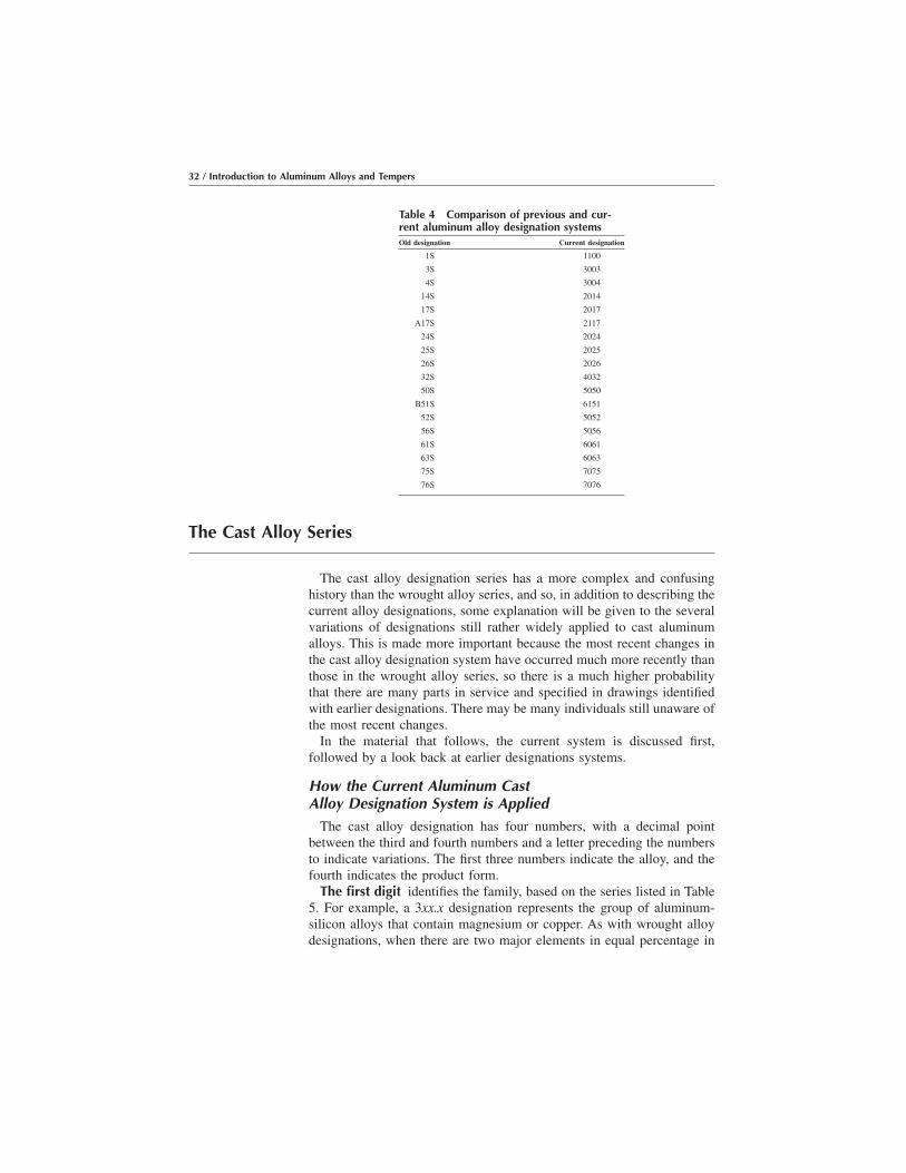
The Cast Alloy Series
The cast alloy designation series has a more complex and confusinghistory than the wrought alloy series, and so, in addition to describing thecurrent alloy designations, some explanation will be given to the severalvariations of designations still rather widely applied to cast aluminumalloys. This is made more important because the most recent changes inthe cast alloy designation system have occurred much more recently thanthose in the wrought alloy series, so there is a much higher probabilitythat there are many parts in service and specified in drawings identifiedwith earlier designations. There may be many individuals still unaware ofthe most recent changes.
In the material that follows, the current system is discussed first,followed by a look back at earlier designations systems.
How the Current Aluminum CastAlloy Designation System is Applied
The cast alloy designation has four numbers, with a decimal pointbetween the third and fourth numbers and a letter preceding the numbersto indicate variations. The first three numbers indicate the alloy, and thefourth indicates the product form.
The first digit identifies the family, based on the series listed in Table5. For example, a 3xx.x designation represents the group of aluminum-silicon alloys that contain magnesium or copper. As with wrought alloydesignations, when there are two major elements in equal percentage in
Table 4 Comparison of previous and cur-rent aluminum alloy designation systemsOld designation Current designation
1S 1100
3S 3003
4S 3004
14S 2014
17S 2017
A17S 2117
24S 2024
25S 2025
26S 2026
32S 4032
50S 5050
B51S 6151
52S 5052
56S 5056
61S 6061
63S 6063
75S 7075
76S 7076
32 / Introduction to Aluminum Alloys and Tempers
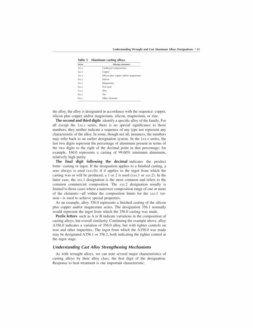
the alloy, the alloy is designated in accordance with the sequence: copper,silicon plus copper and/or magnesium, silicon, magnesium, or zinc.
The second and third digits identify a specific alloy of the family. Forall except the 1xx.x series, there is no special significance to thosenumbers; they neither indicate a sequence of any type nor represent anycharacteristic of the alloy. In some, though not all, instances, the numbersmay refer back to an earlier designation system. In the 1xx.x series, thelast two digits represent the percentage of aluminum present in terms ofthe two digits to the right of the decimal point in that percentage; forexample, 160.0 represents a casting of 99.60% minimum aluminum,relatively high purity.
The final digit following the decimal indicates the productform�casting or ingot. If the designation applies to a finished casting, azero always is used (xxx.0); if it applies to the ingot from which thecasting was or will be produced, a 1 or 2 is used (xxx.1 or xxx.2). In thelatter case, the xxx.1 designation is the most common and refers to thecommon commercial composition. The xxx.2 designation usually islimited to those cases where a narrower composition range of one or moreof the elements—all within the composition limits for the xxx.1 ver-sion—is used to achieve special properties.
As an example, alloy 356.0 represents a finished casting of the siliconplus copper and/or magnesium series. The designation 356.1 normallywould represent the ingot from which the 356.0 casting was made.
Prefix letters such as A or B indicate variations in the composition ofcasting alloys, but overall similarity. Continuing the example above, alloyA356.0 indicates a variation of 356.0 alloy, but with tighter controls oniron and other impurities. The ingot from which the A356.0 was mademay be designated A356.1 or 356.2, both indicating the tighter control atthe ingot stage.
Understanding Cast Alloy Strengthening Mechanisms
As with wrought alloys, we can note several major characteristics ofcasting alloys by their alloy class, the first digit of the designation.Response to heat treatment is one important characteristic:
Table 5 Aluminum casting alloysSeries Alloying element(s)
1xx.x Unalloyed compositions
2xx.x Copper
3xx.x Silicon plus copper and/or magnesium
4xx.x Silicon
5xx.x Magnesium
6xx.x Not used
7xx.x Zinc
8xx.x Tin
9xx.x Other elements
Understanding Wrought and Cast Aluminum Alloys Designations / 33

O 1xx.0: Unalloyed; non-heat-treatable
O 2xx.0: Copper; heat treatable
O 3xx.0: Silicon plus copper and/or magnesium; heat treatable
O 4xx.0: Silicon; heat treatable
O 5xx.0: Magnesium; non-heat-treatable
O 6xx.0: Unused series
O 7xx.0: Zinc; heat treatable
O 8xx.0: Tin; heat treatable
O 9xx.0: Other elements; limited use
Despite these descriptive categorizations, it is appropriate to note thatwhile casting alloys of the 3xx.0 and 4xx.0 groupings are listed as heattreatable, it is not customary in the die-casting industry to use separatesolution heat treatment for these alloys. Some strength advantage isgained by the rapid cooling from the casting process, but even this is notusually a closely controlled procedure. On the other hand, sand andpermanent mold castings foundries typically take advantage of solutionheat treating capabilities.
The reader also will note that there is no discussion of strain hardeningas a strengthening mechanism for cast alloys. This is simply because thevast majority of castings are produced to near-finished dimensions, andneither the shapes nor the dimensional controls lend themselves tostretching or compression cold work.
Understanding Cast Alloy Advantages and Limitations
Based upon the effects of the primary alloying elements, somegeneralizations may be made about several characteristics of the majorclasses of aluminum casting alloys. Among the most important suchcharacteristics are those related to castability and to end-product proper-ties and characteristics, as illustrated in Table 6, with ratings from 1(highest or best) to 5 (lowest or worst). Such ratings are generalizations,and some individual alloys in the groups may exhibit somewhat differentbehavior.
Table 6 Characteristic ratings for cast aluminum alloysClass Fluidity Cracking Tightness Corrosion Finishing Joining
1xx.0 1 1 1
2xx.0 3 4 3 4 1–3 2–4
3xx.0 1–2 1–2 1–2 2–3 3–4 1–3
4xx.0 1 1 1 2–3 4–5 1
5xx.0 5 4 4–5 3 1–2 3
7xx.0 3 4 4 4 1–2 4
8xx.0 4 5 5 5 3 5
34 / Introduction to Aluminum Alloys and Tempers

Examples of the Use of Variations in Cast Alloy Designations
In the cast alloy designations more so than in the wrought series, letterprefixes are used to indicate variations. As noted earlier, an excellentexample is illustrated by A356.0 as a variation of 356.0. Both are readilycastable into complex shapes, but 356.0, because of the relatively greaterimpurity levels tolerated by its specifications (e.g., 0.6% Fe max), may bemore variable in quality, including reduced ductility and toughness.A356.0 is a variation of 356.0 where iron and other impurities arecontrolled to lower levels (e.g., 0.20% Fe max) with the result thatappreciably higher strength, ductility, and toughness are reliably pro-vided.
Another example is A357.0 as a low-impurity variation of 357.0, forwhich the situation is quite parallel.
Alloys for Different Casting Processes
There are a variety of processes that can be employed to producealuminum cast parts, as described in Chapter 5. While many of the alloyscan be produced from a wide variety of these processes, commercial diecastings are generally limited to a relatively small number of composi-tions, namely, 360.0, A360.0, 380.0, A380.0, 383.0, 384.0, A384.0,B390.0, 413.0, C443.0, and 518.0.
Other Characteristics Related to Composition
As with wrought alloys, both density and elastic modulus are directlyrelated to composition, and the same procedures and rules apply.Reference is thus made to an earlier section in this chapter, “OtherCharacteristics Related to Principal Alloying Element,” and to Tables 2and 3 for the procedures on how to estimate these properties from thecompositions.
Evolution of the Aluminum Cast Alloy Designation System
For reference purposes, when links to earlier alloy designation systemsare required, it is useful to note that there have been two gradualtransitions in casting alloy designations. Originally, casting alloys werespecified by a rather randomly applied two- or three-digit designation,without consistent relationships to major alloying elements.
Around 1950, with the increased wrought alloy standardization, therebegan the tendency to standardize casting alloys with three digits, oftenwith the aforementioned letter prefixes, but there were still few specificrules or guidelines guiding alloy designation uniformity.
When the current system was adopted in about 1980, the change wasboth to reform the series designations to make it more reliable andconsistent with regard to alloying constituents and to add the fourth digit,which included the precursor casting ingot from which the castings are
Understanding Wrought and Cast Aluminum Alloys Designations / 35

made. Therefore, at that time, castings designated as 356 castings became356.0, and A356 castings became A356.0; the ingot from which they weremade became 356.1, A356.1, or 356.2, respectively. For some other alloysplaced in the wrong series initially, the change was more drastic: alloy108 became 208.0, alloy 43 became 443.0 (or B443.0), and B214 became512.0.
A summary of some of the major changes over this period is shown inTable 7. Included in this table are both the current and former designa-tions used within the industry, as well as the former designations followedby federal, ASTM, and SAE specifications.
Regrettably, unlike the case with wrought alloys, the current cast alloydesignations are not so widely accepted throughout the world, and in fact,they are not universally accepted even in the United States. While theAmerican Foundrymen’s Society (AFS) and the Non-Ferrous Founders’Society (NFFS) accept and use the Aluminum Association/ANSI castalloy designation system, even the 1996 publications of the Die CastingDevelopment Council still report cast alloy designations without thedecimal point and the fourth digit and, more surprisingly, refer to the alloydesignations used before the alloy series were rationalized by majoralloying element.
UNS Alloy Designation System for Cast AlloysAs noted earlier, the UNS alloy designation system for cast aluminum
alloys, as for wrought aluminum alloys, is based directly on theAluminum Association alloy designation system. For cast alloys, theAluminum Association alloy designation is preceded by “A” followed bya “0” (zero) if there is no letter preceding the alloy designation, or by 1,2, 3, and so on, representing the letter of the alphabet used. No period isused, as in the Aluminum Association casting alloy designation. So, forexample, 356.0 becomes A03560, A356.0 becomes A13560, and B518.0becomes A25180.
36 / Introduction to Aluminum Alloys and Tempers

Table 7 Cross reference chart of aluminum casting alloy designationsAA/ANSI Former UNS Federal Old ASTM Old SAE
201.0 . . . A02010 . . . CQ51A 382
204.0 . . . A02040 . . . . . . . . .
208.0 108 A02080 108 CS43A . . .
213.0 C113 A02130 C113 CS74A 33
222.0 122 A02220 122 CG100A 34
242.0 142 A02420 142 CN42A 39
295.0 195 A02950 195 C4A 38
296.0 B295 A02960 B295 . . . 380
308.0 A108 A03080 A108 . . . . . .
319.0 319, Allcast A03190 319 SC64D 326
328.0 Red X-8 A03280 Red X-8 SC82A 327
332.0 F332.0 A03320 F132 SC103A 332
333.0 333 A03330 333 SC94A 331
336.0 A332.0 A03360 A132 SN122A 321
354.0 354 A03540 . . . . . . . . .
355.0 355 A03550 355 SC51A 322
C355.0 C355 A33550 C355 SC51B 335
356.0 356 A03560 356 SG70A 323
A356.0 A356 A13560 A356 SG70B 336
357.0 357 A03570 357 . . . . . .
A357.0 A357 A13570 . . . . . . . . .
359.0 359 A03590 . . . . . . . . .
360.0 360 A03600 360 SG100B . . .
A360 A360 A13600 A360 SG100A 309
380.0 380 A03800 380 SC84B 308
A380 A380 A13800 A380 SC84A 306
383.0 383 A03830 383 SC102 383
384.0 384 A0384 384 SC114A 303
B390.0 390 A23900 390 SC174B . . .
413.0 13 A04130 13 S12B . . .
A413.0 A13 A14130 A13 S12A 305
443.0 43 A04430 . . . S5B 35
B443.0 43 A24430 43 S5A . . .
C443.0 43 A34430 43 S5C 304
A444.0 . . . A14440 . . . . . . . . .
512.0 B514.0 A05120 B214 GS42A . . .
513.0 A514.0 A05130 A214 GZ42A
514.0 214 A05140 214 G4A 320
518.0 218 A05180 218 G8A . . .
520.0 220 A05200 220 G10A 324
535.0 Almag 35 A05350 Almag 35 GM70B . . .
705.0 603, Ternalloy 5 A07050 Ternalloy 5 ZG32A 311
707.0 607, Ternalloy 7 A07070 Ternalloy 7 ZG42A 312
710.0 A712.0 A07100 A612 ZG61B 313
711.0 C721.0 A07110 . . . ZC60A 314
712.0 D712.0 A07120 40E ZG61A 310
713.0 613, Tenzaloy A07130 Tenzaloy ZC81A 315
771.0 Precedent 71A A07710 Precedent 71A . . . . . .
850.0 750 A08500 750 . . . . . .
851.0 A850.0 A08510 A750 . . . . . .
852.0 B850.0 A08520 B750 . . . . . .
Understanding Wrought and Cast Aluminum Alloys Designations / 37

CHAPTER 4Understanding theAluminum TemperDesignation System
This chapter provides additional detail and illustrations for the use oftemper designations in the aluminum industry today for both wrought andcast alloys. This discussion expands on the basic Aluminum AssociationTemper Designation System as described in Chapter 2. All standardtempers (i.e., those recognized by the industry because they have beenregistered by the Aluminum Association Technical Committee on ProductStandards) are published either in Aluminum Standards and Data or in theAlloy and Temper Registration Records together with the procedures forregistering alloys.
Tempers for Wrought Aluminum Alloys
As noted earlier, temper designations are alphanumeric designationsappended to the alloy designations that convey to the producer and useralike information about the general manner in which the alloy has beenmechanically and/or thermally treated to achieve the properties desired.Most tempers have specific mechanical properties associated with them,and satisfactory achievement of the intended temper is generally indicatedby whether the specified properties have been achieved. The temperdesignation does not indicate precise details of how the material has beentreated, such as specific amounts of reduction during cold rolling, or thetemperatures used in the thermal treatments.
Topics covered in this chapter include:
O Review of basic temper designations and their major variationsO Applications and variations of the O temper
Introduction to Aluminum Alloys and TempersJ. Gilbert Kaufman, p39-76 DOI:10.1361/iaat2000p039
Copyright © 2000 ASM International® All rights reserved. www.asminternational.org
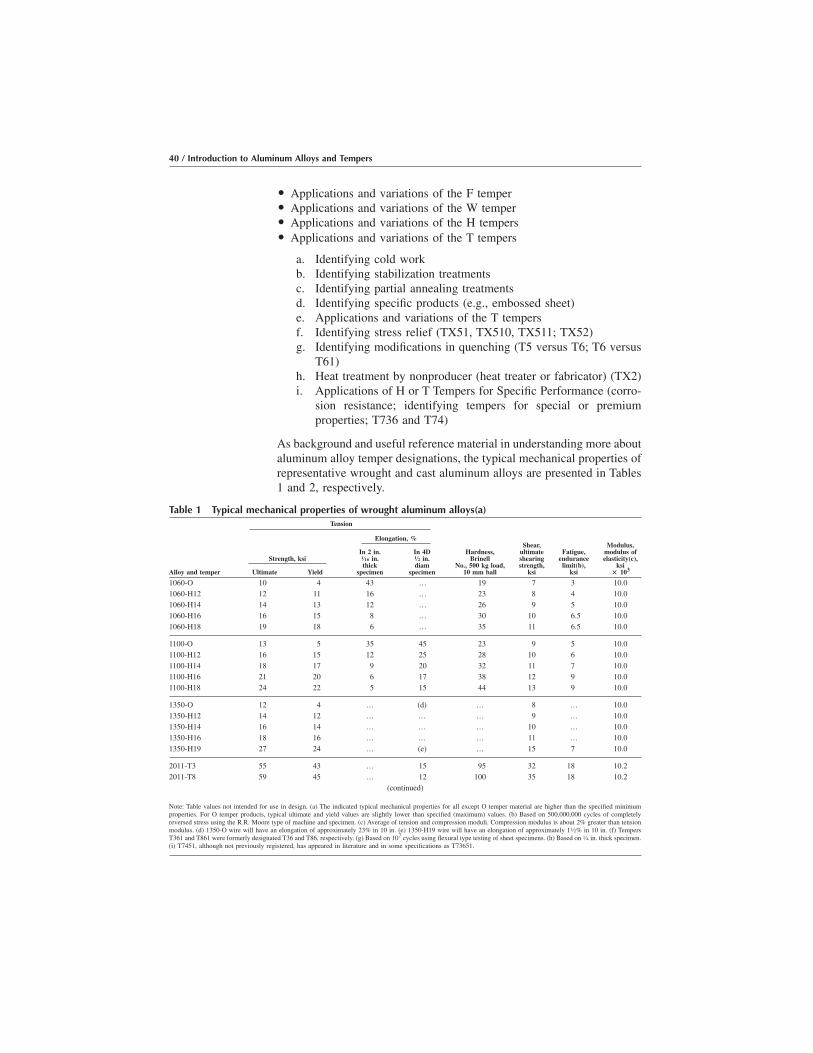
O Applications and variations of the F temperO Applications and variations of the W temperO Applications and variations of the H tempersO Applications and variations of the T tempers
a. Identifying cold workb. Identifying stabilization treatmentsc. Identifying partial annealing treatmentsd. Identifying specific products (e.g., embossed sheet)e. Applications and variations of the T tempersf. Identifying stress relief (TX51, TX510, TX511; TX52)g. Identifying modifications in quenching (T5 versus T6; T6 versus
T61)h. Heat treatment by nonproducer (heat treater or fabricator) (TX2)i. Applications of H or T Tempers for Specific Performance (corro-
sion resistance; identifying tempers for special or premiumproperties; T736 and T74)
As background and useful reference material in understanding more aboutaluminum alloy temper designations, the typical mechanical properties ofrepresentative wrought and cast aluminum alloys are presented in Tables1 and 2, respectively.
Table 1 Typical mechanical properties of wrought aluminum alloys(a)Tension
Elongation, %
Alloy and temper
Strength, ksi
Ultimate Yield
In 2 in.1⁄16 in.thick
specimen
In 4D1⁄2 in.diam
specimen
Hardness,Brinell
No., 500 kg load,10 mm ball
Shear,ultimateshearingstrength,
ksi
Fatigue,endurance
limit(b),ksi
Modulus,modulus ofelasticity(c),
ksi% 103
1060-O 10 4 43 … 19 7 3 10.01060-H12 12 11 16 … 23 8 4 10.01060-H14 14 13 12 … 26 9 5 10.01060-H16 16 15 8 … 30 10 6.5 10.01060-H18 19 18 6 … 35 11 6.5 10.0
1100-O 13 5 35 45 23 9 5 10.01100-H12 16 15 12 25 28 10 6 10.01100-H14 18 17 9 20 32 11 7 10.01100-H16 21 20 6 17 38 12 9 10.01100-H18 24 22 5 15 44 13 9 10.0
1350-O 12 4 … (d) … 8 … 10.01350-H12 14 12 … … … 9 … 10.01350-H14 16 14 … … … 10 … 10.01350-H16 18 16 … … … 11 … 10.01350-H19 27 24 … (e) … 15 7 10.0
2011-T3 55 43 … 15 95 32 18 10.22011-T8 59 45 … 12 100 35 18 10.2
(continued)
Note: Table values not intended for use in design. (a) The indicated typical mechanical properties for all except O temper material are higher than the specified minimumproperties. For O temper products, typical ultimate and yield values are slightly lower than specified (maximum) values. (b) Based on 500,000,000 cycles of completelyreversed stress using the R.R. Moore type of machine and specimen. (c) Average of tension and compression moduli. Compression modulus is about 2% greater than tensionmodulus. (d) 1350-O wire will have an elongation of approximately 23% in 10 in. (e) 1350-H19 wire will have an elongation of approximately 11⁄2% in 10 in. (f) TempersT361 and T861 were formerly designated T36 and T86, respectively. (g) Based on 107 cycles using flexural type testing of sheet specimens. (h) Based on 1⁄4 in. thick specimen.(i) T7451, although not previously registered, has appeared in literature and in some specifications as T73651.
40 / Introduction to Aluminum Alloys and Tempers

Table 1 (continued)Tension
Elongation, %
Alloy and temper
Strength, ksi
Ultimate Yield
In 2 in.1⁄16 in.thick
specimen
In 4D1⁄2 in.diam
specimen
Hardness,Brinell
No., 500 kg load,10 mm ball
Shear,ultimateshearingstrength,
ksi
Fatigue,endurance
limit(b),ksi
Modulus,modulus ofelasticity(c),
ksi% 103
2014-O 27 14 … 18 45 18 13 10.62014-T4, T451 62 42 … 20 105 38 20 10.62014-T6, T651 70 60 … 13 135 42 18 10.6Alclad 2014-O 25 10 21 … … 18 … 10.5Alclad 2014-T3 63 40 20 … … 37 … 10.5
Alclad 2014-T4, T451 61 37 22 … … 37 … 10.5Alclad 2014-T6, T651 68 60 10 … … 41 … 10.52017-O 26 10 … 22 45 18 13 10.52017-T4, T451 62 40 … 22 105 38 18 10.52018-T61 61 46 … 12 120 39 17 10.8
2024-O 27 11 20 22 47 18 13 10.62024-T3 70 50 18 … 120 41 20 10.62024-T4, T351 68 47 20 19 120 41 20 10.62024-T361(f) 72 57 13 … 130 42 18 10.6Alclad 2024-O 26 11 20 … … 18 … 10.6
Alclad 2024-T3 65 45 18 … … 40 … 10.6Alclad 2024-T4, T351 64 42 19 … … 40 … 10.6Alclad 2024-T361(f) 67 63 11 … … 41 … 10.6Alclad 2024-T81, T851 65 60 6 … … 40 … 10.6Alclad 2024-T861(f) 70 66 6 … … 42 … 10.6
2025-T6 58 37 … 19 110 35 18 10.42036-T4 49 28 24 … … … 18(g) 10.32117-T4 43 24 … 27 70 28 14 10.32124-T851 70 64 … 8 … … … 10.62218-T72 48 37 … 11 95 30 … 10.8
2219-O 25 11 18 … … … … 10.62219-T42 52 27 20 … … … … 10.62219-T31, T351 52 36 17 … … … … 10.62219-T37 57 46 11 … … … … 10.62219-T62 60 42 10 … … … 15 10.6
2219-T81, T851 66 51 10 … … … 15 10.62219-T87 69 57 10 … … … 15 10.62618-T61 64 54 … 10 115 38 18 10.83003-O 16 6 30 40 28 11 7 10.03003-H12 19 18 10 20 35 12 8 10.0
3003-H14 22 21 8 16 40 14 9 10.03003-H16 26 25 5 14 47 15 10 10.03003-H18 29 27 4 10 55 16 10 10.0Alclad 3003-O 16 6 30 40 … 11 … 10.0Alclad 3003-H12 19 18 10 20 … 12 … 10.0
Alclad 3003-H14 22 21 8 16 … 14 … 10.0Alclad 3003-H16 26 25 5 14 … 15 … 10.0Alclad 3003-H18 29 27 4 10 … 16 … 10.0
(continued)
Note: Table values not intended for use in design. (a) The indicated typical mechanical properties for all except O temper material are higher than the specified minimumproperties. For O temper products, typical ultimate and yield values are slightly lower than specified (maximum) values. (b) Based on 500,000,000 cycles of completelyreversed stress using the R.R. Moore type of machine and specimen. (c) Average of tension and compression moduli. Compression modulus is about 2% greater than tensionmodulus. (d) 1350-O wire will have an elongation of approximately 23% in 10 in. (e) 1350-H19 wire will have an elongation of approximately 11⁄2% in 10 in. (f) TempersT361 and T861 were formerly designated T36 and T86, respectively. (g) Based on 107 cycles using flexural type testing of sheet specimens. (h) Based on 1⁄4 in. thick specimen.(i) T7451, although not previously registered, has appeared in literature and in some specifications as T73651.
Understanding the Aluminum Temper Designation System / 41

Table 1 (continued)Tension
Elongation, %
Alloy and temper
Strength, ksi
Ultimate Yield
In 2 in.1⁄16 in.thick
specimen
In 4D1⁄2 in.diam
specimen
Hardness,Brinell
No., 500 kg load,10 mm ball
Shear,ultimateshearingstrength,
ksi
Fatigue,endurance
limit(b),ksi
Modulus,modulus ofelasticity(c),
ksi% 103
3004-O 26 10 20 25 45 16 14 10.0
3004-H32 31 25 10 17 52 17 15 10.0
3004-H34 35 29 9 12 63 18 15 10.0
3004-H36 38 33 5 9 70 20 16 10.0
3004-H38 41 36 5 6 77 21 16 10
Alclad 3004-O 26 10 20 25 … 16 … 10.0
Alclad 3004-H32 31 25 10 17 … 17 … 10.0
Alclad 3004-H34 35 29 9 12 … 18 … 10.0
Alclad 3004-H36 38 33 5 9 … 20 … 10.0
Alclad 3004-H38 41 36 5 6 … 21 … 10.0
3105-O 17 8 24 … … 12 … 10.0
3105-H12 22 19 7 … … 14 … 10.0
3105-H14 25 22 5 … … 15 … 10.0
3105-H16 28 25 4 … … 16 … 10.0
3105-H18 31 28 3 … … 17 … 10.0
3105-H25 26 23 8 … … 15 … 10.0
4032-T6 55 46 … 9 120 38 16 11.4
5005-O 18 6 25 … 28 11 … 10.0
5005-H12 20 19 10 … … 14 … 10.0
5005-H14 23 22 6 … … 14 … 10.0
5005-H16 26 25 5 … … 15 … 10.0
5005-H18 29 28 4 … … 16 … 10.0
5005-H32 20 17 11 … 36 14 … 10.0
5005-H34 23 20 8 … 41 14 … 10.0
5005-H36 26 24 6 … 46 15 … 10.0
5005-H38 29 27 5 … 51 16 … 10.0
5050-O 21 8 24 … 36 15 12 10.0
5050-H32 25 21 9 … 46 17 13 10.0
5050-H34 28 24 8 … 53 18 13 10.0
5050-H36 30 26 7 … 58 19 14 10.0
5050-H38 32 29 6 … 63 20 14 10.0
5052-O 28 13 25 30 47 18 16 10.2
5052-H32 33 28 12 18 60 20 17 10.2
5052-H34 38 31 10 14 68 21 18 10.2
5052-H36 40 35 8 10 73 23 19 10.2
5052-H38 42 37 7 8 77 24 20 10.2
5056-O 42 22 … 35 65 26 20 10.3
5056-H18 63 59 … 10 105 34 22 10.3
5056-H38 60 50 … 15 100 32 22 10.3
5083-O 42 21 … 22 … 25 … 10.3
5083-H321, H116 46 33 … 16 … … 23 10.3
(continued)
Note: Table values not intended for use in design. (a) The indicated typical mechanical properties for all except O temper material are higher than the specified minimumproperties. For O temper products, typical ultimate and yield values are slightly lower than specified (maximum) values. (b) Based on 500,000,000 cycles of completelyreversed stress using the R.R. Moore type of machine and specimen. (c) Average of tension and compression moduli. Compression modulus is about 2% greater than tensionmodulus. (d) 1350-O wire will have an elongation of approximately 23% in 10 in. (e) 1350-H19 wire will have an elongation of approximately 11⁄2% in 10 in. (f) TempersT361 and T861 were formerly designated T36 and T86, respectively. (g) Based on 107 cycles using flexural type testing of sheet specimens. (h) Based on 1⁄4 in. thick specimen.(i) T7451, although not previously registered, has appeared in literature and in some specifications as T73651.
42 / Introduction to Aluminum Alloys and Tempers

Table 1 (continued)Tension
Elongation, %
Alloy and temper
Strength, ksi
Ultimate Yield
In 2 in.1⁄16 in.thick
specimen
In 4D1⁄2 in.diam
specimen
Hardness,Brinell
No., 500 kg load,10 mm ball
Shear,ultimateshearingstrength,
ksi
Fatigue,endurance
limit(b),ksi
Modulus,modulus ofelasticity(c),
ksi% 103
5086-O 38 17 22 … … 23 … 10.3
5086-H32, H116 42 30 12 … … … … 10.3.
5086-H34 47 37 10 … … 27 … 10.3
5086-H112 39 19 14 … … … … 10.3
5154-O 35 17 27 … 58 22 17 10.2
5154-H32 39 30 15 … 67 22 18 10.2
5154-H34 42 33 13 … 73 24 19 10.2
5154-H36 45 36 12 … 78 26 20 10.2
5154-H38 48 39 10 … 80 28 21 10.2
5154-H112 35 17 25 … 63 … 17 10.2
5252-H25 34 25 11 … 68 21 … 10.0
5252-H38, H28 41 35 5 … 75 23 … 10.0
5254-O 35 17 27 … 58 22 17 10.2
5254-H32 39 30 15 … 67 22 18 10.2
5254-H34 42 33 13 … 73 24 19 10.2
5254-H36 45 36 12 … 78 26 20 10.2
5254-H38 48 39 10 … 80 28 21 10.2
5254-H112 35 17 25 … 63 … 17 10.2
5454-O 36 17 22 … 62 23 … 10.2
5454-H32 40 30 10 … 73 24 … 10.2
5454-H34 44 35 10 … 81 26 … 10.2
5454-H111 38 26 14 … 70 23 … 10.2
5454-H112 36 18 18 … 62 23 … 10.2
5456-O 45 23 … 24 … … … 10.3
5456-H25 45 24 … 22 … … … 10.3
5456-H321, H116 51 37 … 16 90 30 … 10.3
5457-O 19 7 22 … 32 12 … 10.0
5457-H25 26 23 12 … 48 16 … 10.0
5457-H38, H28 30 27 6 … 55 18 … 10.0
5652-O 28 13 25 30 47 18 16 10.2
5652-H32 33 28 12 18 60 20 17 10.2
5652-H34 38 31 10 14 68 21 18 10.2
5652-H36 40 35 8 10 73 23 19 10.2
5652-H38 42 37 7 8 77 24 20 10.2
5657-H25 23 20 12 … 40 12 … 10.0
5657-H38, H28 28 24 7 … 50 15 … 10.0
6061-O 18 8 25 30 30 12 9 10.0
6061-T4, T451 35 21 22 25 65 24 14 10.0
6061-T6, T651 45 40 12 17 95 30 14 10.0
Alclad 6061-O 17 7 25 … … 11 … 10.0
Alclad 6061-T4, T451 33 19 22 … … 22 … 10.0
(continued)
Note: Table values not intended for use in design. (a) The indicated typical mechanical properties for all except O temper material are higher than the specified minimumproperties. For O temper products, typical ultimate and yield values are slightly lower than specified (maximum) values. (b) Based on 500,000,000 cycles of completelyreversed stress using the R.R. Moore type of machine and specimen. (c) Average of tension and compression moduli. Compression modulus is about 2% greater than tensionmodulus. (d) 1350-O wire will have an elongation of approximately 23% in 10 in. (e) 1350-H19 wire will have an elongation of approximately 11⁄2% in 10 in. (f) TempersT361 and T861 were formerly designated T36 and T86, respectively. (g) Based on 107 cycles using flexural type testing of sheet specimens. (h) Based on 1⁄4 in. thick specimen.(i) T7451, although not previously registered, has appeared in literature and in some specifications as T73651.
Understanding the Aluminum Temper Designation System / 43
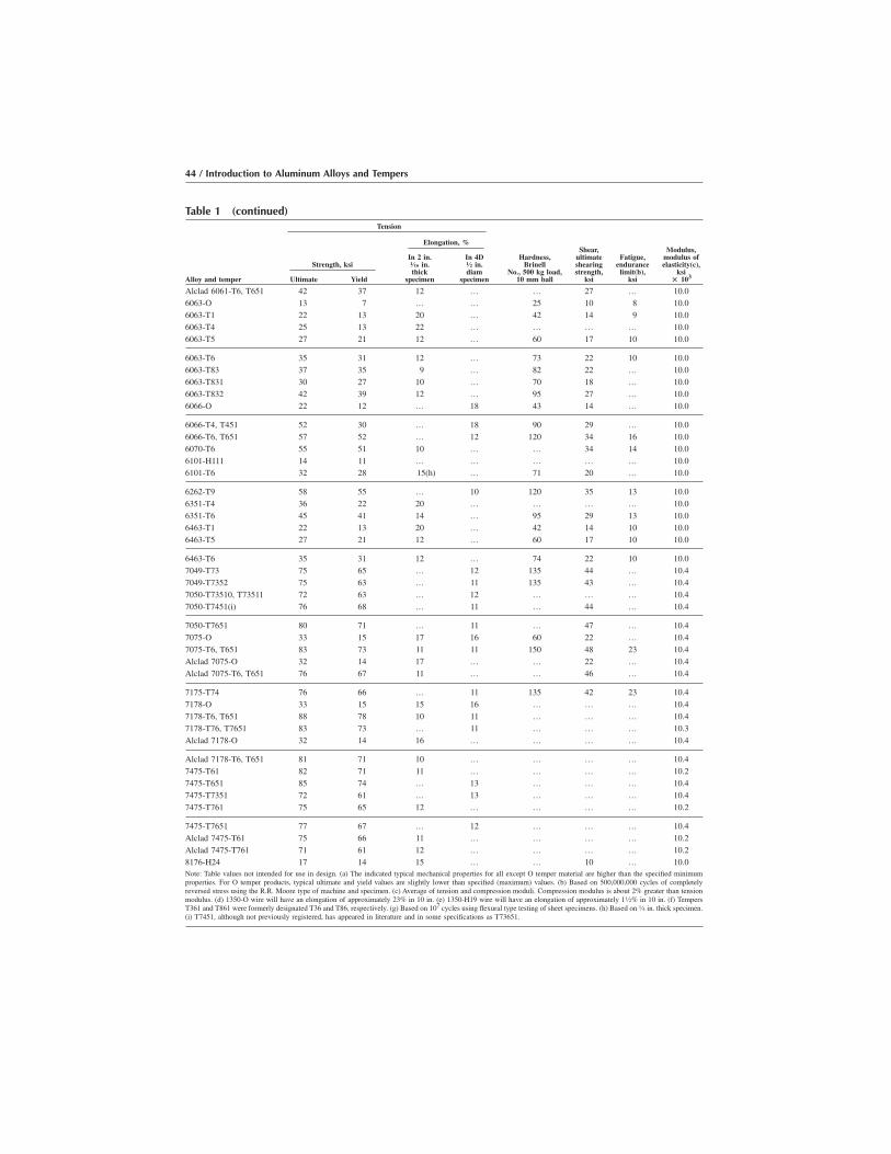
Table 1 (continued)Tension
Elongation, %
Alloy and temper
Strength, ksi
Ultimate Yield
In 2 in.1⁄16 in.thick
specimen
In 4D1⁄2 in.diam
specimen
Hardness,Brinell
No., 500 kg load,10 mm ball
Shear,ultimateshearingstrength,
ksi
Fatigue,endurance
limit(b),ksi
Modulus,modulus ofelasticity(c),
ksi% 103
Alclad 6061-T6, T651 42 37 12 … … 27 … 10.06063-O 13 7 … … 25 10 8 10.06063-T1 22 13 20 … 42 14 9 10.06063-T4 25 13 22 … … … … 10.06063-T5 27 21 12 … 60 17 10 10.0
6063-T6 35 31 12 … 73 22 10 10.06063-T83 37 35 9 … 82 22 … 10.06063-T831 30 27 10 … 70 18 … 10.06063-T832 42 39 12 … 95 27 … 10.06066-O 22 12 … 18 43 14 … 10.0
6066-T4, T451 52 30 … 18 90 29 … 10.06066-T6, T651 57 52 … 12 120 34 16 10.06070-T6 55 51 10 … … 34 14 10.06101-H111 14 11 … … … … … 10.06101-T6 32 28 15(h) … 71 20 … 10.0
6262-T9 58 55 … 10 120 35 13 10.06351-T4 36 22 20 … … … … 10.06351-T6 45 41 14 … 95 29 13 10.06463-T1 22 13 20 … 42 14 10 10.06463-T5 27 21 12 … 60 17 10 10.0
6463-T6 35 31 12 … 74 22 10 10.07049-T73 75 65 … 12 135 44 … 10.47049-T7352 75 63 … 11 135 43 … 10.47050-T73510, T73511 72 63 … 12 … … … 10.47050-T7451(i) 76 68 … 11 … 44 … 10.4
7050-T7651 80 71 … 11 … 47 … 10.47075-O 33 15 17 16 60 22 … 10.47075-T6, T651 83 73 11 11 150 48 23 10.4Alclad 7075-O 32 14 17 … … 22 … 10.4Alclad 7075-T6, T651 76 67 11 … … 46 … 10.4
7175-T74 76 66 … 11 135 42 23 10.47178-O 33 15 15 16 … … … 10.47178-T6, T651 88 78 10 11 … … … 10.47178-T76, T7651 83 73 … 11 … … … 10.3Alclad 7178-O 32 14 16 … … … … 10.4
Alclad 7178-T6, T651 81 71 10 … … … … 10.47475-T61 82 71 11 … … … … 10.27475-T651 85 74 … 13 … … … 10.47475-T7351 72 61 … 13 … … … 10.47475-T761 75 65 12 … … … … 10.2
7475-T7651 77 67 … 12 … … … 10.4Alclad 7475-T61 75 66 11 … … … … 10.2Alclad 7475-T761 71 61 12 … … … … 10.28176-H24 17 14 15 … … 10 … 10.0Note: Table values not intended for use in design. (a) The indicated typical mechanical properties for all except O temper material are higher than the specified minimumproperties. For O temper products, typical ultimate and yield values are slightly lower than specified (maximum) values. (b) Based on 500,000,000 cycles of completelyreversed stress using the R.R. Moore type of machine and specimen. (c) Average of tension and compression moduli. Compression modulus is about 2% greater than tensionmodulus. (d) 1350-O wire will have an elongation of approximately 23% in 10 in. (e) 1350-H19 wire will have an elongation of approximately 11⁄2% in 10 in. (f) TempersT361 and T861 were formerly designated T36 and T86, respectively. (g) Based on 107 cycles using flexural type testing of sheet specimens. (h) Based on 1⁄4 in. thick specimen.(i) T7451, although not previously registered, has appeared in literature and in some specifications as T73651.
44 / Introduction to Aluminum Alloys and Tempers

Table 1M Typical mechanical properties of wrought aluminum alloys, (metric)(a)Tension
Elongation, %
Alloy and temper
Strength, MPa
Ultimate Yield
In 50 mm1.60 mm
thickspecimen
In 5D12.5 mm
diamspecimen
Hardness,Brinell
No., 500 kgf load,10 mm ball
Shear,ultimateshearingstrength,
MPa
Fatigue,endurance
limit(b),MPa
Modulus,modulus ofelasticity(c),MPa % 103
1060-O 70 30 43 … 19 50 20 69
1060-H12 85 75 16 … 23 55 30 69
1060-H14 100 90 12 … 26 60 35 69
1060-H16 115 105 8 … 30 70 45 69
1060-H18 130 125 6 … 35 75 45 69
1100-O 90 35 35 42 23 60 35 69
1100-H12 110 105 12 22 28 70 40 69
1100-H14 125 115 9 18 32 75 50 69
1100-H16 145 140 6 15 38 85 60 69
1100-H18 165 150 5 13 44 90 60 69
1350-O 85 30 … (d) … 55 … 69
1350-H12 95 85 … … … 60 … 69
1350-H14 110 95 … … … 70 … 69
1350-H16 125 110 … … … 75 … 69
1350-H19 185 165 … (e) … 105 50 69
2011-T3 380 295 … 13 95 220 125 70
2011-T8 405 310 … 10 100 240 125 70
2014-O 185 95 … 16 45 125 90 73
2014-T4, T451 425 290 … 18 105 260 140 73
2014-T6, T651 485 415 … 11 135 290 125 73
Alclad 2014-O 170 70 21 … … 125 … 73
Alclad 2014-T3 435 275 20 … … 255 … 73
Alclad 2014-T4, T451 421 255 22 … … 255 … 73
Alclad 2014-T6, T651 470 415 10 … … 285 … 73
2017-O 180 70 … 20 45 125 90 73
2017-T4, T451 425 275 … 20 105 260 125 73
2018-T61 420 315 21 10 120 270 115 74
2024-O 185 75 20 20 47 125 90 73
2024-T3 485 345 18 … 120 285 140 73
2024-T4, T351 472 325 20 17 120 285 140 73
2024-T361(f) 495 395 13 … 130 290 125 73
Alclad 2024-O 180 75 20 … … 125 … 73
Alclad 2024-T3 450 310 18 … … 275 … 73
Alclad 2024-T4, T351 440 290 19 … … 275 … 73
Alclad 2024-T361(f) 460 365 11 … … 285 … 73
Alclad 2024-T81, T851 450 415 6 … … 275 … 73
Alclad 2024-T861(f) 485 455 6 … … 290 … 73
2025-T6 400 255 … 17 110 240 125 72
2036-T4 340 195 24 … … 205 125(g) 71
2117-T4 295 165 … 24 70 195 95 71
2124-T851 485 440 … 8 … … … 73
(continued)
Note: Table values not intended for use in design. (a) The indicated typical mechanical properties for all except O temper material are higher than the specified minimumproperties. For O temper products, typical ultimate and yield values are slightly lower than specified (maximum) values. (b) Based on 500,000,000 cycles of completelyreversed stress using the R.R. Moore type of machine and specimen. (c) Average of tension and compression moduli. Compression modulus is approximately 2% greater thantension modulus. (d) 1350-O wire will have an elongation of approximately 23% in 250 mm. (e) 1350-H19 wire will have an elongation of approximately 11⁄2% in 250 mm.(f) Tempers T361 and T861 formerly were designated T36 and T86, respectively. (g) Based on 107 cycles using flexural type testing of sheet specimens. (h) Based on 6.3 mmthick specimen. (i) T7451, although not previously registered, has appeared in literature and in some specifications as T73651.
Understanding the Aluminum Temper Designation System / 45
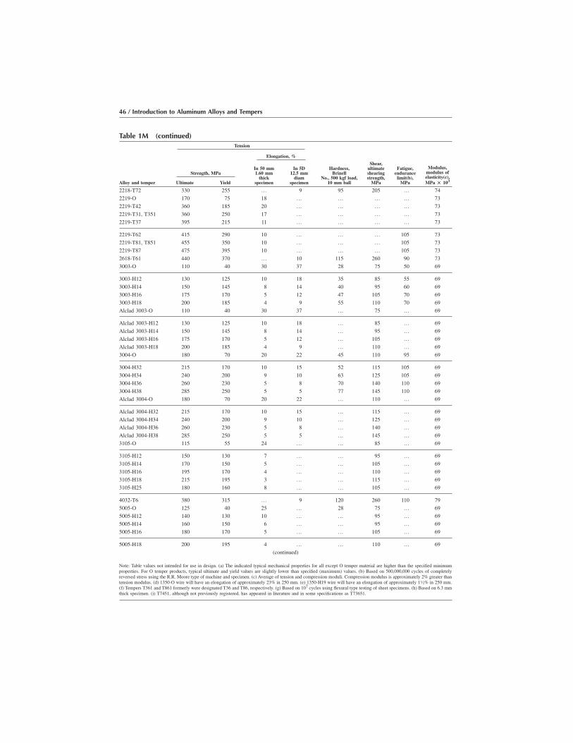
Table 1M (continued)Tension
Elongation, %
Alloy and temper
Strength, MPa
Ultimate Yield
In 50 mm1.60 mm
thickspecimen
In 5D12.5 mm
diamspecimen
Hardness,Brinell
No., 500 kgf load,10 mm ball
Shear,ultimateshearingstrength,
MPa
Fatigue,endurance
limit(b),MPa
Modulus,modulus ofelasticity(c),MPa % 103
2218-T72 330 255 … 9 95 205 … 74
2219-O 170 75 18 … … … … 73
2219-T42 360 185 20 … … … … 73
2219-T31, T351 360 250 17 … … … … 73
2219-T37 395 215 11 … … … … 73
2219-T62 415 290 10 … … … 105 73
2219-T81, T851 455 350 10 … … … 105 73
2219-T87 475 395 10 … … … 105 73
2618-T61 440 370 … 10 115 260 90 73
3003-O 110 40 30 37 28 75 50 69
3003-H12 130 125 10 18 35 85 55 69
3003-H14 150 145 8 14 40 95 60 69
3003-H16 175 170 5 12 47 105 70 69
3003-H18 200 185 4 9 55 110 70 69
Alclad 3003-O 110 40 30 37 … 75 … 69
Alclad 3003-H12 130 125 10 18 … 85 … 69
Alclad 3003-H14 150 145 8 14 … 95 … 69
Alclad 3003-H16 175 170 5 12 … 105 … 69
Alclad 3003-H18 200 185 4 9 … 110 … 69
3004-O 180 70 20 22 45 110 95 69
3004-H32 215 170 10 15 52 115 105 69
3004-H34 240 200 9 10 63 125 105 69
3004-H36 260 230 5 8 70 140 110 69
3004-H38 285 250 5 5 77 145 110 69
Alclad 3004-O 180 70 20 22 … 110 … 69
Alclad 3004-H32 215 170 10 15 … 115 … 69
Alclad 3004-H34 240 200 9 10 … 125 … 69
Alclad 3004-H36 260 230 5 8 … 140 … 69
Alclad 3004-H38 285 250 5 5 … 145 … 69
3105-O 115 55 24 … … 85 … 69
3105-H12 150 130 7 … … 95 … 69
3105-H14 170 150 5 … … 105 … 69
3105-H16 195 170 4 … … 110 … 69
3105-H18 215 195 3 … … 115 … 69
3105-H25 180 160 8 … … 105 … 69
4032-T6 380 315 … 9 120 260 110 79
5005-O 125 40 25 … 28 75 … 69
5005-H12 140 130 10 … … 95 … 69
5005-H14 160 150 6 … … 95 … 69
5005-H16 180 170 5 … … 105 … 69
5005-H18 200 195 4 … … 110 … 69
(continued)
Note: Table values not intended for use in design. (a) The indicated typical mechanical properties for all except O temper material are higher than the specified minimumproperties. For O temper products, typical ultimate and yield values are slightly lower than specified (maximum) values. (b) Based on 500,000,000 cycles of completelyreversed stress using the R.R. Moore type of machine and specimen. (c) Average of tension and compression moduli. Compression modulus is approximately 2% greater thantension modulus. (d) 1350-O wire will have an elongation of approximately 23% in 250 mm. (e) 1350-H19 wire will have an elongation of approximately 11⁄2% in 250 mm.(f) Tempers T361 and T861 formerly were designated T36 and T86, respectively. (g) Based on 107 cycles using flexural type testing of sheet specimens. (h) Based on 6.3 mmthick specimen. (i) T7451, although not previously registered, has appeared in literature and in some specifications as T73651.
46 / Introduction to Aluminum Alloys and Tempers

Table 1M (continued)Tension
Elongation, %
Alloy and temper
Strength, MPa
Ultimate Yield
In 50 mm1.60 mm
thickspecimen
In 5D12.5 mm
diamspecimen
Hardness,Brinell
No., 500 kgf load,10 mm ball
Shear,ultimateshearingstrength,
MPa
Fatigue,endurance
limit(b),MPa
Modulus,modulus ofelasticity(c),MPa % 103
5005-H32 140 115 11 … 36 95 … 69
5005-H34 160 140 8 … 41 95 … 69
5005-H36 180 165 6 … 46 105 … 69
5005-H38 200 185 5 … 51 110 … 69
5050-O 145 55 24 … 36 105 85 69
5050-H32 170 145 9 … 46 115 90 69
5050-H34 190 165 8 … 53 125 90 69
5050-H36 205 180 7 … 58 130 95 69
5050-H38 220 200 6 … 63 140 95 69
5052-O 195 90 25 27 47 125 110 70
5052-H32 230 195 12 16 60 140 115 70
5052-H34 260 215 10 12 68 145 125 70
5052-H36 275 240 8 9 73 160 130 70
5052-H38 290 255 7 7 77 165 140 70
5056-O 290 150 … 32 65 180 140 71
5056-H18 435 405 … 9 105 235 150 71
5056-H38 415 345 … 13 100 220 150 71
5083-O 290 145 … 20 … 170 … 71
5083-H321, H116 315 230 … 14 … … 160 71
5086-O 260 115 22 … … 165 … 71
5086-H32, H116 290 205 12 … … … … 71
5086-H34 325 255 10 … … 185 … 71
5086-H112 270 130 14 … … … … 71
5154-O 240 115 27 … 58 150 115 70
5154-H32 270 205 15 … 67 150 125 70
5154-H34 290 230 13 … 73 165 130 70
5154-H36 310 250 12 … 78 180 140 70
5154-H38 330 270 10 … 80 195 145 70
5154-H112 240 115 25 … 63 … 115 70
5252-H25 235 170 11 … 68 145 … 69
5252-H38, H28 285 240 5 … 75 160 … 69
5254-O 240 115 27 … 58 150 115 70
5254-H32 270 205 15 … 67 150 125 70
5254-H34 290 230 13 … 73 165 130 70
5254-H36 310 250 12 … 78 180 140 70
5254-H38 330 270 10 … 80 195 145 70
5254-H112 240 115 25 … 63 … 115 70
5454-O 250 115 22 … 62 160 … 70
5454-H32 275 205 10 … 73 165 … 70
5454-H34 305 240 10 … 81 180 … 70
5454-H111 260 180 14 … 70 160 … 70
(continued)
Note: Table values not intended for use in design. (a) The indicated typical mechanical properties for all except O temper material are higher than the specified minimumproperties. For O temper products, typical ultimate and yield values are slightly lower than specified (maximum) values. (b) Based on 500,000,000 cycles of completelyreversed stress using the R.R. Moore type of machine and specimen. (c) Average of tension and compression moduli. Compression modulus is approximately 2% greater thantension modulus. (d) 1350-O wire will have an elongation of approximately 23% in 250 mm. (e) 1350-H19 wire will have an elongation of approximately 11⁄2% in 250 mm.(f) Tempers T361 and T861 formerly were designated T36 and T86, respectively. (g) Based on 107 cycles using flexural type testing of sheet specimens. (h) Based on 6.3 mmthick specimen. (i) T7451, although not previously registered, has appeared in literature and in some specifications as T73651.
Understanding the Aluminum Temper Designation System / 47
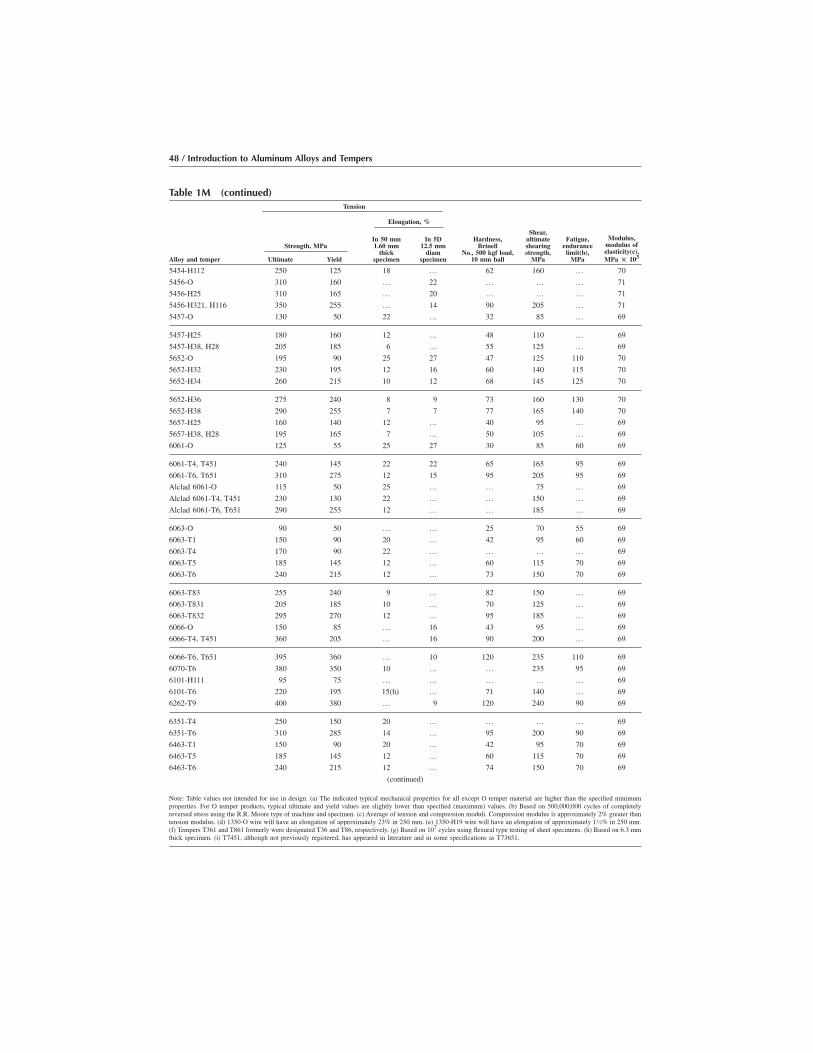
Table 1M (continued)Tension
Elongation, %
Alloy and temper
Strength, MPa
Ultimate Yield
In 50 mm1.60 mm
thickspecimen
In 5D12.5 mm
diamspecimen
Hardness,Brinell
No., 500 kgf load,10 mm ball
Shear,ultimateshearingstrength,
MPa
Fatigue,endurance
limit(b),MPa
Modulus,modulus ofelasticity(c),MPa % 103
5454-H112 250 125 18 … 62 160 … 70
5456-O 310 160 … 22 … … … 71
5456-H25 310 165 … 20 … … … 71
5456-H321, H116 350 255 … 14 90 205 … 71
5457-O 130 50 22 … 32 85 … 69
5457-H25 180 160 12 … 48 110 … 69
5457-H38, H28 205 185 6 … 55 125 … 69
5652-O 195 90 25 27 47 125 110 70
5652-H32 230 195 12 16 60 140 115 70
5652-H34 260 215 10 12 68 145 125 70
5652-H36 275 240 8 9 73 160 130 70
5652-H38 290 255 7 7 77 165 140 70
5657-H25 160 140 12 … 40 95 … 69
5657-H38, H28 195 165 7 … 50 105 … 69
6061-O 125 55 25 27 30 85 60 69
6061-T4, T451 240 145 22 22 65 165 95 69
6061-T6, T651 310 275 12 15 95 205 95 69
Alclad 6061-O 115 50 25 … … 75 … 69
Alclad 6061-T4, T451 230 130 22 … … 150 … 69
Alclad 6061-T6, T651 290 255 12 … … 185 … 69
6063-O 90 50 … … 25 70 55 69
6063-T1 150 90 20 … 42 95 60 69
6063-T4 170 90 22 … … … … 69
6063-T5 185 145 12 … 60 115 70 69
6063-T6 240 215 12 … 73 150 70 69
6063-T83 255 240 9 … 82 150 … 69
6063-T831 205 185 10 … 70 125 … 69
6063-T832 295 270 12 … 95 185 … 69
6066-O 150 85 … 16 43 95 … 69
6066-T4, T451 360 205 … 16 90 200 … 69
6066-T6, T651 395 360 … 10 120 235 110 69
6070-T6 380 350 10 … … 235 95 69
6101-H111 95 75 … … … … … 69
6101-T6 220 195 15(h) … 71 140 … 69
6262-T9 400 380 … 9 120 240 90 69
6351-T4 250 150 20 … … … … 69
6351-T6 310 285 14 … 95 200 90 69
6463-T1 150 90 20 … 42 95 70 69
6463-T5 185 145 12 … 60 115 70 69
6463-T6 240 215 12 … 74 150 70 69
(continued)
Note: Table values not intended for use in design. (a) The indicated typical mechanical properties for all except O temper material are higher than the specified minimumproperties. For O temper products, typical ultimate and yield values are slightly lower than specified (maximum) values. (b) Based on 500,000,000 cycles of completelyreversed stress using the R.R. Moore type of machine and specimen. (c) Average of tension and compression moduli. Compression modulus is approximately 2% greater thantension modulus. (d) 1350-O wire will have an elongation of approximately 23% in 250 mm. (e) 1350-H19 wire will have an elongation of approximately 11⁄2% in 250 mm.(f) Tempers T361 and T861 formerly were designated T36 and T86, respectively. (g) Based on 107 cycles using flexural type testing of sheet specimens. (h) Based on 6.3 mmthick specimen. (i) T7451, although not previously registered, has appeared in literature and in some specifications as T73651.
48 / Introduction to Aluminum Alloys and Tempers

Table 2 Typical mechanical properties of aluminum alloy castings
Tension
Type of castingAlloy
and temperUltimate
strength, ksi
Yieldstrength(a),
ksi
Elongationin 2 in.
or 4D, %
Hardness,Brinell No.,
500kg/10mm
Shear,ultimatestrength,
ksi
Fatigue,endurance
limit(b),ksi
Modulusof
elasticity(c),106 ksi
Sand 201.0-T6 65 55 8 130 … … …
201.0-T7 68 60 6 … … 14 …
201.0-T43 60 37 17 … … … …
204.0-T4 45 28 6 … … … …
A206.0-T4 51 36 7 … 40 … …
208.0-F 21 14 3 … 17 11 …
213.0-F 24 15 2 70 20 9 …
222.0-O 27 20 1 80 21 9.5
222.0-T61 41 40 <0.5 115 32 8.5 10.7
224.0-T72 55 40 10 123 35 9 10.5
(continued)
Values are representative of separately cast test bars, not of specimens taken from commercial castings. (a) For tensile yield strengths, offset � 0.2%. (b) Based on 500,000,000cycles of completely reversed stress using R.R. Moore type of machines and specimens. (c) Average of tension and compression moduli; compressive modulus is nominallyapproximately 2% greater. Data taken from various industry handbooks.
Table 1M (continued)Tension
Elongation, %
Alloy and temper
Strength, MPa
Ultimate Yield
In 50 mm1.60 mm
thickspecimen
In 5D12.5 mm
diamspecimen
Hardness,Brinell
No., 500 kgf load,10 mm ball
Shear,ultimateshearingstrength,
MPa
Fatigue,endurance
limit(b),MPa
Modulus,modulus ofelasticity(c),MPa % 103
7049-T73 515 450 … 10 135 305 … 727049-T7352 515 435 … 9 135 295 … 727050-T73510, T73511 495 435 … 11 … … … 727050-T7451(i) 525 470 … 10 … 305 … 727050-T7651 550 490 … 10 … 325 … 72
7075-O 230 105 17 14 60 150 … 727075-T6, T651 570 505 11 9 150 330 160 72Alclad 7075-O 220 95 17 … … 150 … 72Alclad 7075-T6, T651 525 460 11 … … 315 … 727175-T74 525 455 … 10 135 290 160 72
7178-O 230 105 15 14 … … … 727178-T6, T651 605 540 10 9 … … … 727178-T76, T7651 570 505 … 9 … … … 71Alclad 7178-O 220 95 16 … … … … 72Alclad 7178-T6, T651 560 460 10 … … … … 72
7475-T61 565 490 11 … … … … 707475-T651 585 510 … 13 … … … 727475-T7351 495 420 … 13 … … … 727475-T761 515 450 12 … … … … 707475-T7651 530 460 … 12 … … … 72
Alclad 7475-T61 515 455 11 … … … … 70Alclad 7475-T761 490 420 12 … … … … 708176-H24 160 95 15 … … 70 … 69Note: Table values not intended for use in design. (a) The indicated typical mechanical properties for all except O temper material are higher than the specified minimumproperties. For O temper products, typical ultimate and yield values are slightly lower than specified (maximum) values. (b) Based on 500,000,000 cycles of completelyreversed stress using the R.R. Moore type of machine and specimen. (c) Average of tension and compression moduli. Compression modulus is approximately 2% greater thantension modulus. (d) 1350-O wire will have an elongation of approximately 23% in 250 mm. (e) 1350-H19 wire will have an elongation of approximately 11⁄2% in 250 mm.(f) Tempers T361 and T861 formerly were designated T36 and T86, respectively. (g) Based on 107 cycles using flexural type testing of sheet specimens. (h) Based on 6.3 mmthick specimen. (i) T7451, although not previously registered, has appeared in literature and in some specifications as T73651.
Understanding the Aluminum Temper Designation System / 49
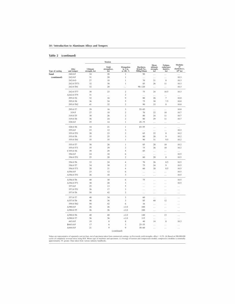
Table 2 (continued)
Tension
Type of castingAlloy
and temperUltimate
strength, ksi
Yieldstrength(a),
ksi
Elongationin 2 in.
or 4D, %
Hardness,Brinell No.,
500kg/10mm
Shear,ultimatestrength,
ksi
Fatigue,endurance
limit(b),ksi
Modulusof
elasticity(c),106 ksi
Sand 240.0-F 34 28 1 90 … … …(continued) 242.0-F 31 20 1 … … … 10.3
242.0-O 27 18 1 70 21 8 10.3242.0-T571 32 30 1 85 26 11 10.3242.0-T61 32 20 … 90–120 … … 10.3
242.0-T77 30 23 2 75 24 10.5 10.3A242.0-T75 31 … 2 … … … …
295.0-T4 32 16 9 80 26 7 10.0295.0-T6 36 24 5 75 30 7.5 10.0295.0-T62 41 32 2 90 33 8 10.0
295.0-T7 29 16 3 55–85 … … 10.0319-F 27 18 2 70 22 10 10.7
319.0-T5 30 26 2 80 24 11 10.7319.0-T6 36 24 2 80 29 11 10.7328.0-F 25 14 1 45–75 … … …
328.0-T6 34 21 1 65–95 … … …355.0-F 23 12 3 … … … 10.2355.0-T51 28 23 2 65 22 8 10.2355.0-T6 35 25 3 80 28 9 10.2355.0-T61 35 35 1 90 31 9.5 10.2
355.0-T7 38 26 1 85 28 10 10.2355.0-T71 35 29 2 75 26 10 10.2
C355.0-T6 39 29 5 85 … … …356.0-F 24 18 6 … … … 10.5356.0-T51 25 20 2 60 20 8 10.5
356.0-T6 33 24 4 70 26 8.5 10.5356.0-T7 34 30 2 75 24 9 10.5356.0-T71 28 21 4 60 20 8.5 10.5
A356.0-F 23 12 6 … … … 10.5A356.0-T51 26 18 3 … … … 10.5
A356.0-T6 40 30 6 75 … … 10.5A356.0-T71 30 20 3 … … … 10.5
357.0-F 25 13 5 … … … …357.0-T51 26 17 3 … … … …357.0-T6 50 42 2 … … … …
357.0-T7 40 34 3 60 … … …A357.0-T6 46 36 3 85 40 12 …
359.0-T62 50 42 6 16 … … …A390.0-F 26 26 <1.0 100 … … …A390.0-T5 26 26 <1.0 100 … … …
A390.0-T6 40 40 <1.0 140 … 13 …A390.0-T7 36 36 <1.0 115 … … …
443.0-F 19 8 8 40 14 8 10.3B443.0-F 17 6 3 25–55 … … …A444.0-F 21 9 9 30–60 … … …
(continued)
Values are representative of separately cast test bars, not of specimens taken from commercial castings. (a) For tensile yield strengths, offset � 0.2%. (b) Based on 500,000,000cycles of completely reversed stress using R.R. Moore type of machines and specimens. (c) Average of tension and compression moduli; compressive modulus is nominallyapproximately 2% greater. Data taken from various industry handbooks.
50 / Introduction to Aluminum Alloys and Tempers

Table 2 (continued)
Tension
Type of castingAlloy
and temperUltimate
strength, ksi
Yieldstrength(a),
ksi
Elongationin 2 in.
or 4D, %
Hardness,Brinell No.,
500kg/10mm
Shear,ultimatestrength,
ksi
Fatigue,endurance
limit(b),ksi
Modulusof
elasticity(c),106 ksi
Sand A444.0-T4 23 9 12 43 … … …(continued) 511.0-F 21 12 3 50 17 8 …
512.0-F 20 13 2 50 17 9 …514.0-F 25 12 9 50 20 7 …520.0-T4 48 26 16 75 34 8 …
535.0-F 35 18 9 60–90 … … …535.0-T5 35 18 9 60–90 … … …
A535.0-F 36 18 9 65 … … …707.0-T5 33 22 2 70–100 … … …707.0-T7 37 30 1 65–95 … … …
710.0-F 32 20 2 60–90 … … …710.0-T5 32 20 2 60–90 … … …712.0-F 34 25 4 60–90 … … …712.0-T5 34 25 4 60–90 … … …713.0-F 32 22 3 60–90 … … …
713.0-T5 32 22 3 60–90771.0-T5 32 27 3 70–100 … … …771.0-T52 36 30 2 70–100 … … …771.0-T53 36 27 2 … … … …771.0-T6 42 35 5 75–105 … … …
771.0-T71 48 45 2 105–135 … … …850.0-T5 20 11 8 45 14 … 10.3851.0-T5 20 11 5 45 14 … 10.3852.0-T5 27 22 2 65 18 10 10.3
Permanent mold 201.0-T6 65 55 8 130 … … …201.0-T7 68 60 6 … … 14 …201.0-T43 60 37 17 … … … …204.0-T4 48 29 8 … … … …
A206.0-T4 62 38 17 … 42 … …
A206.0-T7 63 50 12 … 37 … …208.0-T6 35 22 2 75–105 … … …208.0-T7 33 16 3 65–95 … … …213.0-F 30 24 2 85 24 9.5 …222.0-T551 37 35 <0.5 115 30 8.5 10.7
222.0-T52 35 31 1 100 25 … 10.7238.0-F 30 24 2 100 24 … …242.0-T61 47 42 1 110 35 10 10.3
A249.0-T63 69 60 6 … … … …296.0-T7 39 20 5 80 30 9 10.1
308.0-F 28 16 2 70 22 13 …319.0-F 34 19 3 85 24 … 10.7319.0-T6 40 27 3 95 … … 10.7324.0-F 30 16 4 70 … … …324.0-T5 36 26 3 90 … … …
324.0-T62 45 39 3 105 … … …(continued)
Values are representative of separately cast test bars, not of specimens taken from commercial castings. (a) For tensile yield strengths, offset � 0.2%. (b) Based on 500,000,000cycles of completely reversed stress using R.R. Moore type of machines and specimens. (c) Average of tension and compression moduli; compressive modulus is nominallyapproximately 2% greater. Data taken from various industry handbooks.
Understanding the Aluminum Temper Designation System / 51

Table 2 (continued)
Tension
Type of castingAlloy
and temperUltimate
strength, ksi
Yieldstrength(a),
ksi
Elongationin 2 in.
or 4D, %
Hardness,Brinell No.,
500kg/10mm
Shear,ultimatestrength,
ksi
Fatigue,endurance
limit(b),ksi
Modulusof
elasticity(c),106 ksi
Permanent mold 332.0-T5 36 28 1 105 … … …(continued) 328.0-T6 34 21 1 65–95 … … …
333.0-F 34 19 2 90 27 15 …242.0-T571 40 34 1 105 30 10.5 10.3333.0-T5 34 25 1 100 27 12 …
333.0-T6 42 30 2 105 33 15 …333.0-T7 37 28 2 90 28 12 …336.0-T551 36 28 1 105 28 14 …336.0-T65 47 43 1 125 36 … …354.0-T61 48 37 3 … … … …
354.0-T62 52 42 2 … … … …355.0-F 27 15 4 … … … 10.2355.0-T51 30 24 2 75 24 … 10.2355.0-T6 42 27 4 90 34 10 10.2355.0-T61 45 40 2 105 36 10 10.2
355.0-T7 40 30 2 85 30 10 10.2355.0-T71 36 31 3 85 27 10 10.2
C355.0-T6 48 28 8 90 … … 10.2C355.0-T61 46 34 6 100 … … 10.2C355.0-T62 48 37 5 100 … … 10.2
356.0-F 26 18 5 … … … 10.5356.0-T51 27 20 2 … … … 10.5356.0-T6 38 27 5 80 30 13 10.5356.0-T7 32 24 6 70 25 11 10.5356.0-T71 25 … 3 60–90 … … 10.5
A356.0-F 27 13 8 … … … 10.5A356.0-T51 29 20 5 … … … 10.5A356.0-T6 41 30 12 80 … … 10.5
357.0-F 28 15 6 … … … …357.0-T51 29 21 4 … … … …
357.0-T6 52 43 5 100 35 13 …357.0-T7 38 30 5 70 … … …
A357.0-T6 52 42 5 100 35 15 …359.0-T61 48 37 6 … … … …359.0-T62 50 42 6 … … 16 …
A390.0-F 29 29 <1.0 110 … … …A390.0-T5 29 29 <1.0 110 … … …A390.0-T6 45 45 <1.0 145 … 17 …A390.0-T7 38 38 <1.0 120 … 15 …
443.0-F 23 9 10 45 16 8 10.3
B443.0-F 21 6 6 30–60 … … …A444.0-F 24 11 13 44 … … …A444.0-T4 23 10 21 45 16 8 …
513.0-F 27 16 7 60 22 10 …535.0-F 35 18 8 60–90 … … …
705.0-T5 37 17 10 55–75 … … …(continued)
Values are representative of separately cast test bars, not of specimens taken from commercial castings. (a) For tensile yield strengths, offset � 0.2%. (b) Based on 500,000,000cycles of completely reversed stress using R.R. Moore type of machines and specimens. (c) Average of tension and compression moduli; compressive modulus is nominallyapproximately 2% greater. Data taken from various industry handbooks.
52 / Introduction to Aluminum Alloys and Tempers
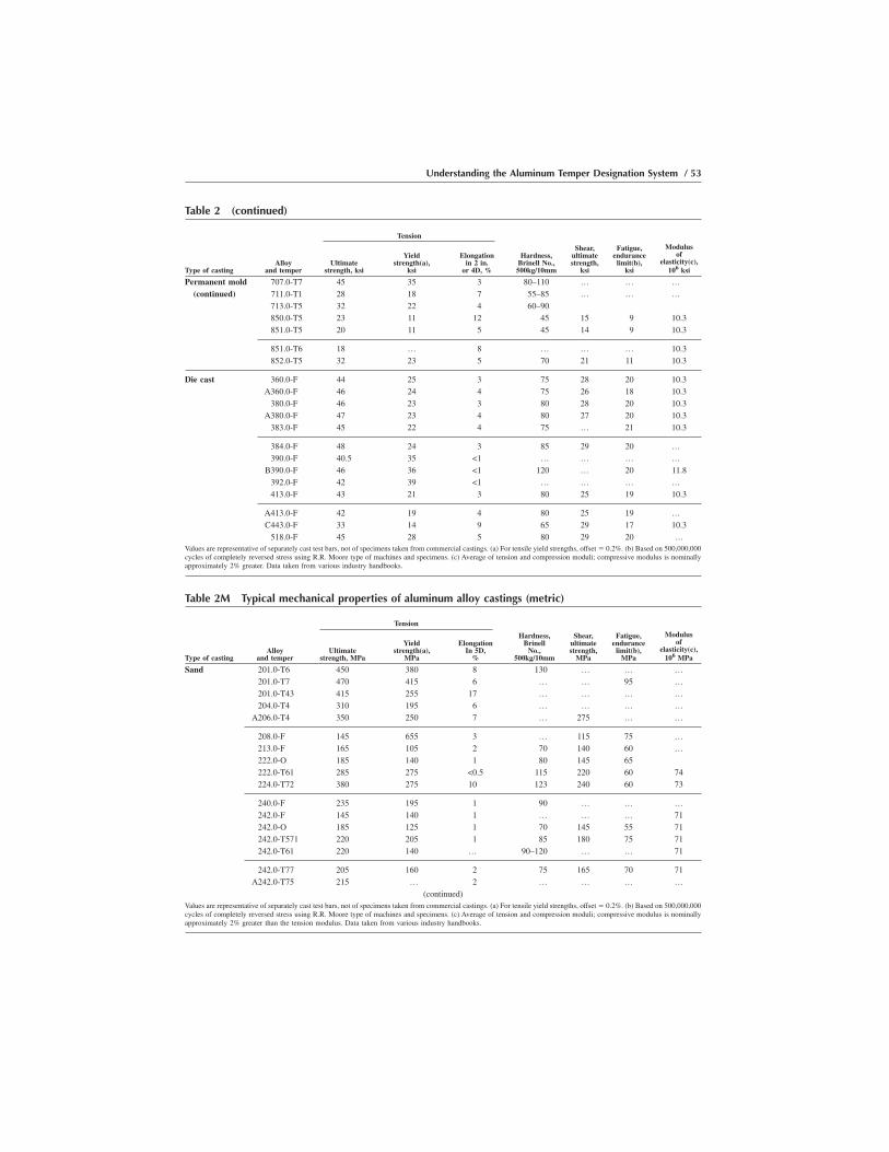
Table 2M Typical mechanical properties of aluminum alloy castings (metric)
Tension
Type of castingAlloy
and temperUltimate
strength, MPa
Yieldstrength(a),
MPa
ElongationIn 5D,
%
Hardness,Brinell
No.,500kg/10mm
Shear,ultimatestrength,
MPa
Fatigue,endurance
limit(b),MPa
Modulusof
elasticity(c),106 MPa
Sand 201.0-T6 450 380 8 130 … … …201.0-T7 470 415 6 … … 95 …201.0-T43 415 255 17 … … … …204.0-T4 310 195 6 … … … …
A206.0-T4 350 250 7 … 275 … …
208.0-F 145 655 3 … 115 75 …213.0-F 165 105 2 70 140 60 …222.0-O 185 140 1 80 145 65222.0-T61 285 275 <0.5 115 220 60 74224.0-T72 380 275 10 123 240 60 73
240.0-F 235 195 1 90 … … …242.0-F 145 140 1 … … … 71242.0-O 185 125 1 70 145 55 71242.0-T571 220 205 1 85 180 75 71242.0-T61 220 140 … 90–120 … … 71
242.0-T77 205 160 2 75 165 70 71A242.0-T75 215 … 2 … … … …
(continued)Values are representative of separately cast test bars, not of specimens taken from commercial castings. (a) For tensile yield strengths, offset � 0.2%. (b) Based on 500,000,000cycles of completely reversed stress using R.R. Moore type of machines and specimens. (c) Average of tension and compression moduli; compressive modulus is nominallyapproximately 2% greater than the tension modulus. Data taken from various industry handbooks.
Table 2 (continued)
Tension
Type of castingAlloy
and temperUltimate
strength, ksi
Yieldstrength(a),
ksi
Elongationin 2 in.
or 4D, %
Hardness,Brinell No.,
500kg/10mm
Shear,ultimatestrength,
ksi
Fatigue,endurance
limit(b),ksi
Modulusof
elasticity(c),106 ksi
Permanent mold 707.0-T7 45 35 3 80–110 … … …(continued) 711.0-T1 28 18 7 55–85 … … …
713.0-T5 32 22 4 60–90850.0-T5 23 11 12 45 15 9 10.3851.0-T5 20 11 5 45 14 9 10.3
851.0-T6 18 … 8 … … … 10.3852.0-T5 32 23 5 70 21 11 10.3
Die cast 360.0-F 44 25 3 75 28 20 10.3A360.0-F 46 24 4 75 26 18 10.3
380.0-F 46 23 3 80 28 20 10.3A380.0-F 47 23 4 80 27 20 10.3
383.0-F 45 22 4 75 … 21 10.3
384.0-F 48 24 3 85 29 20 …390.0-F 40.5 35 <1 … … … …
B390.0-F 46 36 <1 120 … 20 11.8392.0-F 42 39 <1 … … … …413.0-F 43 21 3 80 25 19 10.3
A413.0-F 42 19 4 80 25 19 …C443.0-F 33 14 9 65 29 17 10.3
518.0-F 45 28 5 80 29 20 …Values are representative of separately cast test bars, not of specimens taken from commercial castings. (a) For tensile yield strengths, offset � 0.2%. (b) Based on 500,000,000cycles of completely reversed stress using R.R. Moore type of machines and specimens. (c) Average of tension and compression moduli; compressive modulus is nominallyapproximately 2% greater. Data taken from various industry handbooks.
Understanding the Aluminum Temper Designation System / 53

Table 2M (continued)
Tension
Type of castingAlloy
and temperUltimate
strength, MPa
Yieldstrength(a),
MPa
ElongationIn 5D,
%
Hardness,Brinell
No.,500kg/10mm
Shear,ultimatestrength,
MPa
Fatigue,endurance
limit(b),MPa
Modulusof
elasticity(c),106 MPa
Sand 295.0-T4 220 110 9 80 180 50 69(continued) 295.0-T6 250 165 5 75 205 50 69
295.0-T62 285 220 2 90 230 55 69295.0-T7 200 110 3 55–85 … … 69
319-F 185 125 2 70 150 70 74
319.0-T5 205 180 2 80 165 75 74319.0-T6 250 165 2 80 200 75 74328.0-F 170 95 1 45–75 … … …328.0-T6 235 145 1 65–95 … … …355.0-F 160 85 3 … … … 70
355.0-T51 195 160 2 65 150 55 70355.0-T6 240 170 3 80 195 60 70355.0-T61 240 240 1 90 215 65 70355.0-T7 260 180 1 85 195 70 70355.0-T71 240 200 2 75 180 70 70
C355.0-T6 270 200 5 85 … … …356.0-F 165 125 6 … … … 73356.0-T51 170 140 2 60 140 55 73356.0-T6 230 135 4 70 180 60 73356.0-T7 235 205 2 75 165 60 73
356.0-T71 195 145 4 60 140 60 73A356.0-F 160 85 6 … … … 73A356.0-T51 180 125 3 … … … 73A356.0-T6 275 205 6 75 … … 73A356.0-T71 205 140 3 … … … 73
357.0-F 170 90 5 … … … …357.0-T51 180 115 3 … … … …357.0-T6 345 295 2 … … … …357.0-T7 275 235 3 60 … … …
A357.0-T6 315 250 3 85 275 85 …
359.0-T62 345 290 6 16 … … …A390.0-F 180 180 <1.0 100 … … …A390.0-T5 180 180 <1.0 100 … … …A390.0-T6 275 275 <1.0 140 … 90 …A390.0-T7 250 250 <1.0 115 … … …
443.0-F 130 55 8 40 95 55 71B443.0-F 115 40 3 25–55 … … …A444.0-F 145 60 9 30–60 … … …A444.0-T4 23 60 12 43 … … …
511.0-F 145 85 3 50 115 55 …
512.0-F 140 90 2 50 115 60 …514.0-F 170 85 9 50 140 50 …520.0-T4 330 180 16 75 235 55 …535.0-F 240 125 9 60–90 … … …535.0-T5 240 125 9 60–90 … … …
A535.0-F 250 125 9 65 … … …(continued)
Values are representative of separately cast test bars, not of specimens taken from commercial castings. (a) For tensile yield strengths, offset � 0.2%. (b) Based on 500,000,000cycles of completely reversed stress using R.R. Moore type of machines and specimens. (c) Average of tension and compression moduli; compressive modulus is nominallyapproximately 2% greater than the tension modulus. Data taken from various industry handbooks.
54 / Introduction to Aluminum Alloys and Tempers

Table 2M (continued)
Tension
Type of castingAlloy
and temperUltimate
strength, MPa
Yieldstrength(a),
MPa
ElongationIn 5D,
%
Hardness,Brinell
No.,500kg/10mm
Shear,ultimatestrength,
MPa
Fatigue,endurance
limit(b),MPa
Modulusof
elasticity(c),106 MPa
Sand 707.0-T5 230 150 2 70–100 … … …(continued) 707.0-T7 255 205 1 65–95 … … …
710.0-F 220 140 2 60–90 … … …710.0-T5 220 140 2 60–90 … … …712.0-F 235 170 4 60–90 … … …
712.0-T5 235 170 4 60–90 … … …713.0-F 220 150 3 60–90 … … …713.0-T5 220 150 3 60–90771.0-T5 220 185 3 70–100 … … …771.0-T52 250 205 2 70–100 … … …
771.0-T53 250 185 2 … … … …771.0-T6 290 240 5 75–105 … … …771.0-T71 330 310 2 105–135 … … …850.0-T5 140 75 8 45 95 … 71851.0-T5 140 75 5 45 95 … 71852.0-T5 185 150 2 65 125 60 71
Permanent mold 201.0-T6 450 380 8 130 … … …201.0-T7 470 415 6 … … 95 …201.0-T43 415 255 17 … … … …204.0-T4 330 200 8 … … … …
A206.0-T4 430 260 17 … 290 … …
A206.0-T7 435 345 12 … 255 … …208.0-T6 240 150 2 75–105 … … …208.0-T7 230 110 3 65–95 … … …213.0-F 205 165 2 85 165 65 …222.0-T551 255 240 <0.5 115 205 60 74
222.0-T52 240 215 1 100 170 … 74238.0-F 205 165 2 100 165 … …242.0-T571 275 235 1 105 205 70 74242.0-T61 325 290 1 110 450 70 74
A249.0-T63 475 415 6 … … … …
296.0-T7 270 140 5 80 205 60 70308.0-F 195 110 2 70 150 90 …319.0-F 235 130 3 85 165 … 74319.0-T6 275 185 3 95 … … 74324.0-F 205 110 4 70 … … …
324.0-T5 250 180 3 90 … … …324.0-T62 310 270 3 105 … … …332.0-T5 250 195 1 105 … … …328.0-T6 235 145 1 65–95 … … …333.0-F 235 130 2 90 185 105 …
333.0-T5 235 170 1 100 185 85 …333.0-T6 290 205 2 105 230 105 …333.0-T7 255 195 2 90 195 85 …336.0-T551 250 193 1 105 193 95 …
(continued)
Values are representative of separately cast test bars, not of specimens taken from commercial castings. (a) For tensile yield strengths, offset � 0.2%. (b) Based on 500,000,000cycles of completely reversed stress using R.R. Moore type of machines and specimens. (c) Average of tension and compression moduli; compressive modulus is nominallyapproximately 2% greater than the tension modulus. Data taken from various industry handbooks.
Understanding the Aluminum Temper Designation System / 55
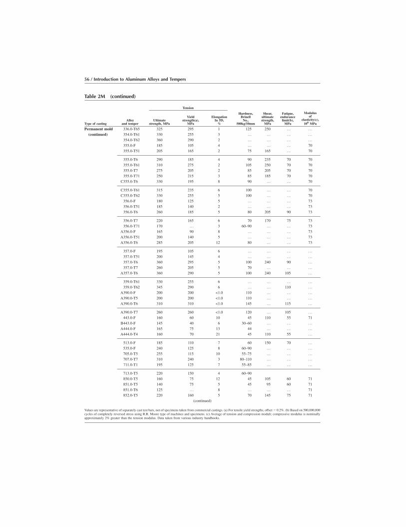
Table 2M (continued)
Tension
Type of castingAlloy
and temperUltimate
strength, MPa
Yieldstrength(a),
MPa
ElongationIn 5D,
%
Hardness,Brinell
No.,500kg/10mm
Shear,ultimatestrength,
MPa
Fatigue,endurance
limit(b),MPa
Modulusof
elasticity(c),106 MPa
Permanent mold 336.0-T65 325 295 1 125 250 … …(continued) 354.0-T61 330 255 3 … … … …
354.0-T62 360 290 2 … … … …355.0-F 185 105 4 … … … 70355.0-T51 205 165 2 75 165 … 70
355.0-T6 290 185 4 90 235 70 70355.0-T61 310 275 2 105 250 70 70355.0-T7 275 205 2 85 205 70 70355.0-T71 250 215 3 85 185 70 70
C355.0-T6 330 195 8 90 … … 70
C355.0-T61 315 235 6 100 … … 70C355.0-T62 330 255 5 100 … … 70
356.0-F 180 125 5 … … … 73356.0-T51 185 140 2 … … … 73356.0-T6 260 185 5 80 205 90 73
356.0-T7 220 165 6 70 170 75 73356.0-T71 170 … 3 60–90 … … 73
A356.0-F 165 90 8 … … … 73A356.0-T51 200 140 5 … … … 73A356.0-T6 285 205 12 80 … … 73
357.0-F 195 105 6 … … … …357.0-T51 200 145 4 … … … …357.0-T6 360 295 5 100 240 90 …357.0-T7 260 205 5 70 … … …
A357.0-T6 360 290 5 100 240 105 …
359.0-T61 330 255 6 … … … …359.0-T62 345 290 6 … … 110 …
A390.0-F 200 200 <1.0 110 … … …A390.0-T5 200 200 <1.0 110 … … …A390.0-T6 310 310 <1.0 145 … 115 …
A390.0-T7 260 260 <1.0 120 … 105 …443.0-F 160 60 10 45 110 55 71
B443.0-F 145 40 6 30–60 … … …A444.0-F 165 75 13 44 … … …A444.0-T4 160 70 21 45 110 55 …
513.0-F 185 110 7 60 150 70 …535.0-F 240 125 8 60–90 … … …705.0-T5 255 115 10 55–75 … … …707.0-T7 310 240 3 80–110 … … …711.0-T1 195 125 7 55–85 … … …
713.0-T5 220 150 4 60–90850.0-T5 160 75 12 45 105 60 71851.0-T5 140 75 5 45 95 60 71851.0-T6 125 … 8 … … … 71852.0-T5 220 160 5 70 145 75 71
(continued)
Values are representative of separately cast test bars, not of specimens taken from commercial castings. (a) For tensile yield strengths, offset � 0.2%. (b) Based on 500,000,000cycles of completely reversed stress using R.R. Moore type of machines and specimens. (c) Average of tension and compression moduli; compressive modulus is nominallyapproximately 2% greater than the tension modulus. Data taken from various industry handbooks.
56 / Introduction to Aluminum Alloys and Tempers

Review of the Basic Tempers for Wrought Alloys
The temper designation always is presented immediately following thealloy designation (Chapter 3), with a hyphen between the two (e.g.,2014-T6). Generally, the temper designation consists of a capital letterindicating the major class of fabrication treatment(s) used, plus one ormore numbers providing more specific information about how theprocessing was carried out. These designations are not intended toprovide the exact practices (times, temperatures, reductions), but ratherthe general combinations of practices followed.
As review, recall that the first character in the temper designation (acapital letter, F, O, H, W, or T) indicates the general class of treatment.Information on each of these classes of designation and a few examplesof each are provided by the following descriptions:
O F, as fabricated: This designation is used for wrought or cast productsmade by some shaping process such as rolling, extrusion, forging,drawing, or casting where there is no special control over the thermalconditions during working or the strain-hardening processes to achievespecific properties. There are no specified limits on mechanicalproperties of any wrought F temper product. Except in the case of castparts, which may be in the final configuration, most F temper productsare “semifinished” products that will be used in some subsequentshaping, finishing, or thermal process to achieve other finished formsor tempers. For example, 2014-F designates an as-fabricated productform of alloy 2014; it may represent any production process or product
Table 2M (continued)
Tension
Type of castingAlloy
and temperUltimate
strength, MPa
Yieldstrength(a),
MPa
ElongationIn 5D,
%
Hardness,Brinell
No.,500kg/10mm
Shear,ultimatestrength,
MPa
Fatigue,endurance
limit(b),MPa
Modulusof
elasticity(c),106 MPa
Die cast 360.0-F 305 170 3 75 195 140 71A360.0-F 315 165 4 75 180 124 71
380.0-F 315 160 3 80 195 140 71A380.0-F 325 160 4 80 185 140 71
383.0-F 310 150 4 75 … 145 71
384.0-F 330 165 3 85 200 140 …390.0-F 280 240 <1 … … … …
B390.0-F 315 250 <1 120 … 140 81392.0-F 290 270 <1 … … … …413.0-F 295 145 3 80 170 130 71
A413.0-F 290 130 4 80 170 130 …C443.0-F 230 95 9 65 200 115 71
518.0-F 310 193 5 80 200 140 …Values are representative of separately cast test bars, not of specimens taken from commercial castings. (a) For tensile yield strengths, offset � 0.2%. (b) Based on 500,000,000cycles of completely reversed stress using R.R. Moore type of machines and specimens. (c) Average of tension and compression moduli; compressive modulus is nominallyapproximately 2% greater than the tension modulus. Data taken from various industry handbooks.
Understanding the Aluminum Temper Designation System / 57

form and may be used for products that have been rolled, extruded,forged, or any combination of those processes.
O O, annealed: This designation is used for wrought or cast productsmade by some shaping process such as rolling, extrusion, forging,drawing, or casting, and which product at some point in the process hasbeen annealed (i.e., given a high-temperature recrystallization treat-ment, sufficient to remove the effects of any prior working or thermaltreatments and usually resulting in complete recrystallization of thematerial). Annealing treatments are used to achieve the lowest-strengthcondition for the particular alloy involved. The primary reason forusing such a treatment on wrought alloys generally is to maximizesubsequent workability or increase toughness and ductility to amaximum. For example:
a. 2014-O designates any product form of 2014 whose most recenttreatment has been holding at a high temperature (�410 °C, or�770 °F) for 2 to 3 h, slow cooling to �260 °C (�500 °F) and thencooling at an uncontrolled rate to room temperature. For this alloy,the treatment would normally be given to increase ease of subse-quent working while completely removing any effects of priortreatments.
b. 5083-O designates any product form of 5083 whose most recenttreatment has been heating up to a high temperature (�345 °C,�650 °F) and then cooled at an uncontrolled rate to roomtemperature. For this alloy, the treatment would normally be givento increase toughness and ductility for its use in critical structuralapplications such as liquefied natural gas tanks.
O H, strain hardened: This designation is used for non-heat-treatablewrought alloys that have had their strength increased by strainhardening (e.g., rolling, drawing) usually at room temperature. Thisdesignation may, but does not necessarily, also apply to products thathave been given supplementary thermal treatments to achieve somestabilization in strength level, since a number of aluminum alloys willgradually soften slightly with time after cold working. The H is alwaysfollowed by two or more digits, the purpose of which is to indicate theapproximate amount of cold work and the nature of any thermaltreatments that followed. The variety of subsequent designationsavailable is discussed later, so the examples focus more on the Hdesignation itself at this point. For example:
a. 1350-H12 indicates that sheet, plate, rod, or wire of alloy 1350 hasbeen cold worked to increase its strength. The H12 combinationindicates approximately 20 to 25% cold reduction without anysubsequent thermal treatments (other variations are discussed later).
58 / Introduction to Aluminum Alloys and Tempers

b. 5005-H18 indicates that sheet (the only product available in thattemper) of alloy 5005 has been cold rolled to increase its strength.The H18 combination indicates a large amount of cold work,normally around 75 to 80% without any subsequent thermaltreatment.
O W, solution heat treated: This designation is rather limited in its useand applies only to alloys that age naturally and spontaneously aftersolution heat treating (holding at high temperature followed byquenching or relatively rapid cooling to room temperature). Digits maybe added to characterize more specifically the elapsed time since thecooling took place; this is not necessary and is of limited value sincethe time may continue to increase, but it is often helpful in whateversubsequent treatments are to be applied to know that elapsed time andthe effects of the elapsed time on response to subsequent working orthermal exposure. As with the F temper, there are no publishedstandard property limits for wrought alloys associated with the Wtemper, and it is rarely a “finished” temper (i.e., sold in that temper; itis always an “in-process” temper, to be followed by subsequentmechanical or thermal treatments). For example:
a. 6061-W indicates a semifinished product of 6061 that has beenheat treated and quenched by standard procedures but not yetgiven any subsequent mechanical or thermal treatment. Alloy6061 naturally ages following a quench from a heat treatment, andso the yield strength, in particular, of this material graduallyincreases with time until some treatment that will stabilize itsproperties is given, such as artificial aging for precipitationhardening.
b. 6061-W1⁄2hr. indicates the same material as in the precedingexample, except that a time (1⁄2 h after quenching) has been addedto define the time lapse and perhaps permit some estimate of theeffect on strength (assuming that aging rate data are accessible).
O T, thermally treated to produce stable tempers other than F, O, or H:The T designation is the most widely used for heat treated alloys, andapplies to any product form of any heat treatable alloy that has beengiven a solution heat treatment followed by a suitable quench andeither natural (i.e., in air) or artificial (i.e., in a furnace) aging. The Talways is followed by one or more digits that define in general termsthe subsequent treatments; these will be discussed in more detail later,and so the following examples focus on the T designation. Forexample:
a. 2024-T4 indicates a 2024 product that has been solution heattreated, quenched, and naturally aged by standard commercial pro-cesses to a stable condition. Since this alloy achieves a com-mercially useful level of strength coupled with a high toughness inthe T4 condition, this may well be the final temper designation.
Understanding the Aluminum Temper Designation System / 59

b. 2014-T4 indicates an alloy 2014 product that has been solutionheat treated and naturally aged to a stable condition preparatory toartificially aging it for precipitation hardening to the T6 temper.Alloy 2014 does not have a useful combination of strength,toughness, and corrosion resistance in the T4 condition, so it isalmost always subsequently given a precipitation hardeningtreatment.
Subdivisions of the Basic Tempers
As just indicated, most of the basic temper designations listed previ-ously are used with additional numerical digits to define the practicesmore completely. It is useful to review these additional digits and theresulting complete designations in considerable detail to obtain the bestunderstanding of their meanings.
The H and T are the most frequently used tempers and are, therefore,discussed sequentially. The F, O, and W designations are generally usedalone and provide the complete description, and thus there is little to sayabout them except for one minor variation of the O temper that is coveredlater.
Subdivisions of the H Temper for Non-Heat-Treatable Alloys. TheH temper indicates that the alloy involved has been cold worked by strainhardening. The H always is followed by at least two numbers:
O The first number after the H tells whether the strain-hardened alloy hasbeen thermally treated and, if so, by what procedure.
O The second number indicates approximately how much the alloy wasstrain hardened (i.e., the approximate percentage of cold reduction).
O Any subsequent numbers define special practices, variations of thenormal indicated by the first two numbers.
The first number, indicating variations in thermal treatments followingcold work, may be one of four possibilities:
O H1 indicates that processing was limited to strain hardening; there wasno subsequent thermal treatment.
O H2 indicates strain hardening followed by a partial high-temperaturerecrystallization thermal treatment (i.e., a partial anneal) to take theproperties back to some stable level less than those achieved by thecold working. When this temper is used, the alloy has intentionallybeen strain hardened more than the desired amount and then partiallyannealed back to achieve a specific level of strength.
O H3 indicates strain hardening followed by a thermal stabilizationtreatment (i.e., holding at a modestly elevated temperature to permitthe properties to stabilize and avoid time-dependent age softening, to
60 / Introduction to Aluminum Alloys and Tempers

which certain alloys, especially of the 5xxx series, are prone). This alsomay be accomplished by the heat applied during a subsequent forming.
O H4 indicates strain hardening followed by some thermal operation suchas paint curing or lacquering in which the heat applied during thisprocessing effectively reduces the degree of hardening remaining in thealloy and provides some stabilization to the final properties. It is usefulto note that there are no unique property limits associated with H4Xtempers; rather, the property limits associated with the comparableH2X or H3X tempers are used.
As noted earlier, these H1, H2, H3, and H4 designations always arefollowed by a second number that indicates the approximate amount ofcold work.
Examples of the application of these designations include:
O 3003-H12: Strain hardened approximately 25%; no other treatment(i.e., meets properties for H12 temper)
O 3005-H26: Strain hardened and partial annealed to effective strainhardening of about 75% (i.e., meets properties for H26 temper)
O 5052-H32: Strain hardened and stabilized to effective strain hardeningof about 25% (i.e., meets properties for H32 temper)
O 5052-H42: Strain hardened and given some finishing treatment thatprovides effective strain hardening of approximately 25% (i.e., meetsproperties for H42/H22 temper)
As indicated by these examples, the digit following H1, H2, H3, or H4,indicates the effective degree of strain hardening remaining in the metalfollowing the sequence of operations indicated by the first digit. In otherwords:
O H1X temper: The X represents the actual amount of strain hardeninggiven the alloy; no thermal treatment has been given to reduce theeffective work remaining in the metal.
O H2X temper: The X represents the effective cold work remaining afterthe metal has been cold worked beyond the final level desired, andpartial annealed back.
O H3X and H4X tempers: The X indicates the effective cold workremaining in the metal following cold working and the intermediatetemperature stabilization treatment or the thermal exposure involved inthe subsequent forming, painting, or lacquering processes.
The second numerical digits have both a technical definition accordingto the Aluminum Association and a “schematic,” or approximate, defini-tion as used in the trade. According to the Aluminum Association rules,the second digit is defined based upon the minimum value of the ultimate
Understanding the Aluminum Temper Designation System / 61
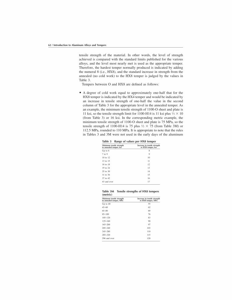
tensile strength of the material. In other words, the level of strengthachieved is compared with the standard limits published for the variousalloys, and the level most nearly met is used as the appropriate temper.Therefore, the hardest temper normally produced is indicated by addingthe numeral 8 (i.e., HX8), and the standard increase in strength from theannealed (no cold work) to the HX8 temper is judged by the values inTable 3.
Tempers between O and HX8 are defined as follows:
O A degree of cold work equal to approximately one-half that for theHX8 temper is indicated by the HX4 temper and would be indicated byan increase in tensile strength of one-half the value in the secondcolumn of Table 3 for the appropriate level in the annealed temper. Asan example, the minimum tensile strength of 1100-O sheet and plate is11 ksi, so the tensile strength limit for 1100-H14 is 11 ksi plus 1⁄2 � 10(from Table 3) or 16 ksi. In the corresponding metric example, theminimum tensile strength of 1100-O sheet and plate is 75 MPa, so thetensile strength of 1100-H14 is 75 plus 1⁄2 � 75 (from Table 3M) or112.5 MPa, rounded to 110 MPa. It is appropriate to note that the rulesin Tables 3 and 3M were not used in the early days of the aluminum
Table 3 Range of values per HX8 temperMinimum tensile strengthin annealed temper, ksi
Increase in tensile strengthto HX8 temper, ksi
Up to 6 8
7 to 9 9
10 to 12 10
13 to 15 11
16 to 18 12
19 to 24 13
25 to 30 14
31 to 36 15
37 to 42 16
43 and over 17
Table 3M Tensile strengths of HX8 tempers(metric)Minimum tensile strengthin annealed temper, MPa
Increase in tensile strengthto HX8 temper, MPa
Up to 40 55
45–60 62
65–80 69
85–100 76
105–120 83
125–160 90
165–200 97
205–240 103
245–280 110
285–320 115
296 and over 120
62 / Introduction to Aluminum Alloys and Tempers

industry, and so there are exceptions among long-established propertyvalues.
O A degree of cold work halfway between the O temper and the HX4temper is indicated by the HX2 temper; a degree of cold work halfwaybetween HX4 and HX8 is the HX6 temper. Following the examplegiven for 1100, the respective tensile strength limits would be 14 ksifor H12 and 19 ksi for H16, respectively (the 0.5 ksi increments beingrounded up). As a metric example for 1100, the respective tensilestrength limit would be 130 MPa for H16, midway between the H14and H18 values.
O The numbers 1, 3, 5, and 7 similarly designate tempers intermediatebetween those just listed. In practice, these designations are seldomused; when they are, as in the case of 5657-H25, it is usually for somespecial product to indicate a specific treatment given to enhance somespecific property (brightness, in the example given). The odd-num-bered tempers also are used for pattern sheet temper designations, asdescribed later.
O The numeral 9 is used to indicate tempers with properties exceedingthose of HX8 by 14 MPa (2 ksi) or more. This temper is achieved bycold rolling sheet to very small thicknesses, usually only a fewthousandths of an inch. This designation also is used only for specialproducts; the most important example is 3004-H19 sheet for can stock(i.e., starting stock for the production of aluminum cans).
Some additional examples of two-digit H tempers that illustrate use ofthe first and second digits include the following:
O 3003-H14: The “1” indicates that the material has been strain hardenedand given no subsequent processing; the “4” indicates that the amountof strain hardening was about 50% of the level for the H18, or“full-hard” temper.
O 5657-H26: The “2” indicates that the alloy has been strain hardened arelatively large amount and then partially annealed back to the desiredlevel of effective cold work; the “6” indicates that the effective finallevel of cold work was about 80% of that of the full-hard H18 temper.
O 5086-H32: The “3” indicates that the alloy has been strain hardenedand stabilized; the “2” indicates that the degree of strain hardening wasabout 25% of the level for the H38 temper. Applications include sheet,plate, and drawn tube.
Three-digit H Tempers. The final group of subdivisions of the H tempersthat needs to be recognized involves the use of a third numeric digit forthe H tempers. A third digit, such as HXX1, indicates a variation in atwo-digit temper. Differences may be in such things as the degree of
Understanding the Aluminum Temper Designation System / 63
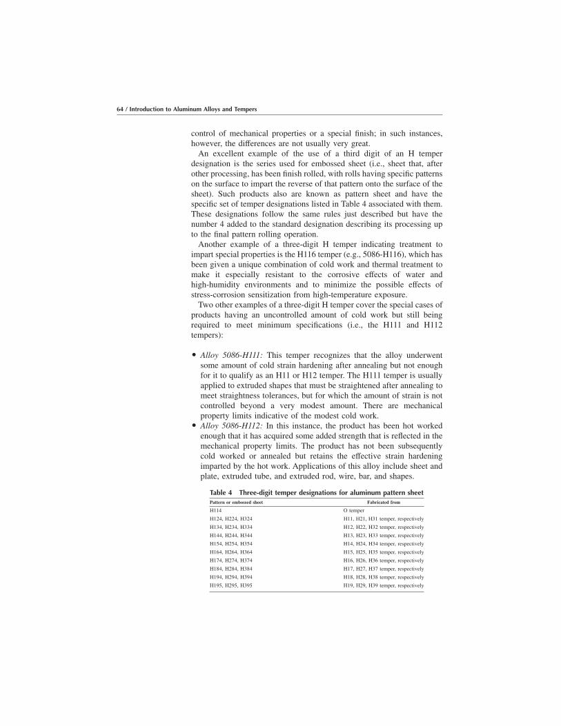
control of mechanical properties or a special finish; in such instances,however, the differences are not usually very great.
An excellent example of the use of a third digit of an H temperdesignation is the series used for embossed sheet (i.e., sheet that, afterother processing, has been finish rolled, with rolls having specific patternson the surface to impart the reverse of that pattern onto the surface of thesheet). Such products also are known as pattern sheet and have thespecific set of temper designations listed in Table 4 associated with them.These designations follow the same rules just described but have thenumber 4 added to the standard designation describing its processing upto the final pattern rolling operation.
Another example of a three-digit H temper indicating treatment toimpart special properties is the H116 temper (e.g., 5086-H116), which hasbeen given a unique combination of cold work and thermal treatment tomake it especially resistant to the corrosive effects of water andhigh-humidity environments and to minimize the possible effects ofstress-corrosion sensitization from high-temperature exposure.
Two other examples of a three-digit H temper cover the special cases ofproducts having an uncontrolled amount of cold work but still beingrequired to meet minimum specifications (i.e., the H111 and H112tempers):
O Alloy 5086-H111: This temper recognizes that the alloy underwentsome amount of cold strain hardening after annealing but not enoughfor it to qualify as an H11 or H12 temper. The H111 temper is usuallyapplied to extruded shapes that must be straightened after annealing tomeet straightness tolerances, but for which the amount of strain is notcontrolled beyond a very modest amount. There are mechanicalproperty limits indicative of the modest cold work.
O Alloy 5086-H112: In this instance, the product has been hot workedenough that it has acquired some added strength that is reflected in themechanical property limits. The product has not been subsequentlycold worked or annealed but retains the effective strain hardeningimparted by the hot work. Applications of this alloy include sheet andplate, extruded tube, and extruded rod, wire, bar, and shapes.
Table 4 Three-digit temper designations for aluminum pattern sheetPattern or embossed sheet Fabricated from
H114 O temper
H124, H224, H324 H11, H21, H31 temper, respectively
H134, H234, H334 H12, H22, H32 temper, respectively
H144, H244, H344 H13, H23, H33 temper, respectively
H154, H254, H354 H14, H24, H34 temper, respectively
H164, H264, H364 H15, H25, H35 temper, respectively
H174, H274, H374 H16, H26, H36 temper, respectively
H184, H284, H384 H17, H27, H37 temper, respectively
H194, H294, H394 H18, H28, H38 temper, respectively
H195, H295, H395 H19, H29, H39 temper, respectively
64 / Introduction to Aluminum Alloys and Tempers

Subdivisions of the T Temper for Heat Treatable Alloys. The Ttempers for heat treatable alloys may have from one to five digitsfollowing the T, and there are many more possible combinations than forthe H tempers. The first digit after the T always indicates the basic typeof treatment, and the second to fifth, if they are used, indicate whether theproduct was stress relieved and, if so, how it was stress relieved, andwhether any other special treatments were given.
The first digit after the T may be any of the following:
O T1: Indicates that the alloy has been cooled directly from somehigh-temperature hot-working process such as rolling or extrusion andthen naturally aged to a stable condition. As a result, it has received an“effective heat treatment,” but it has not received any other processingsuch as cold work that is recognized by special mechanical propertylimits. This temper is not widely used because, among other things, thecorrosion resistance of the material may not be as good as with othercombinations of treatments.
O T2: Indicates that the alloy has been cooled from some high-temperature hot-working process such as rolling or extrusion and thencold worked before being naturally aged to a stable condition. Hereagain, the alloy has received an “effective heat treatment” as a result ofthe high-temperature treatment, but in this case, it has been coldworked sufficiently to increase its strength. This temper, as the T1, isnot widely used because of limitations in certain characteristicscompared with those given other combinations of treatments describedas follows:
O T3: Indicates the alloy has been given a solution heat treatmentfollowing hot working, quenching, cold working, and being naturallyaged to a stable condition. This temper, like T4, T6, T7, and T8,indicates the use of a specific solution heat treatment (i.e., holding ina furnace at a sufficiently high temperature for the important alloyingelements to go into solution, where they are retained upon quenchingand provide a source of precipitation-hardening constituents). Theamount of cold work is controlled to provide specific amounts of strainhardening with a commensurate increase in strength. This is a widelyused temper type for 2xxx series alloys such as 2024, which naturallyage efficiently following cold work.
O T4: Indicates the alloy has been given a solution heat treatment and,without any cold work, naturally aged to a stable condition. Thistemper also is rather widely used for the 2xxx alloys.
O T5: Indicates the alloy has been cooled from a high-temperatureshaping process, usually extrusion, and then, without any intermediatecold work, is artificially aged. The artificial aging consists of holdingat a sufficiently high temperature and sufficiently long time (e.g., 8 h at175 °C, or 350 °F, or 24 h at 120 °C, or 250 °F) to permit precipitation
Understanding the Aluminum Temper Designation System / 65

hardening to take place. If there is any straightening or flattening tomeet dimensional tolerances, it is not sufficient to be recognized withhigher mechanical property limits.
O T6: Indicates the alloy has been solution heat treated and, without anysignificant cold working, artificially aged to achieve precipitationhardening. If there is any straightening or flattening to meet dimen-sional tolerances, it is not sufficient to be recognized with highermechanical property limits.
O T7: Indicates the alloy has been solution heat treated and, without anysignificant cold working, aged in a furnace to an overaged (i.e., pastpeak strength) condition (also sometimes referred to as stabilized).This treatment generally is used for the 7xxx series alloys (e.g.,7075-T73 or T76) to improve their resistance to either stress-corrosioncracking (SCC) (T73) or to exfoliation corrosion (T76) attack; the T73is the more severely overaged condition (see the subsequent section“Tempers Designating Special Corrosion-Resistant Tempers”).
O T8: Indicates the alloy has been solution heat treated, cold worked forstrain hardening, and then artificially aged to achieve precipitationhardening. The material also may have been cold worked primarily tomeet dimensional or stress relief requirements, but if the T8 temper isused, the amount of cold work is sufficient to be recognized by highermechanical property limits. This temper primarily is used for the 2xxxalloys (e.g., 2024-T81 sheet).
O T9: Indicates the alloy has been solution heat treated, artificially agedto achieve precipitation hardening, and then cold worked to improve itsstrength. This temper is not widely used but is applied to the 2xxx seriesin some cases.
O T10: Indicates the alloy has been cooled from a high-temperatureshaping process such as extrusion, cold worked, and then artificiallyaged for precipitation hardening. This temper rarely is used becausethere are no current commercial applications for it.
In all of the T-type tempers just described, solution heat treatment isachieved by heating semifinished or finished products to a suitabletemperature, holding them at that temperature long enough to allowconstituents to go into solution, and cooling them rapidly enough to holdthe constituents in solution so that they may be the basis of precipitationhardening upon natural (i.e., room temperature) or artificial (i.e., in afurnace) aging.
Adding Additional Digits to the T1 to T10 Tempers. Additionaldigits, the first of which shall not be zero, may be added to designationsT1 to T10 to indicate a variation in treatment that significantly alters theproduct characteristics that are or would be obtained using the basictreatment. There is no standard listing of all such possible variations, so
66 / Introduction to Aluminum Alloys and Tempers
the best way to illustrate and understand this usage better is to examinethe major examples, as in the following sections that cover:
O Stress reliefO Heat treatment by userO Variations in heat treatment proceduresO Variations in quenching proceduresO Addition of cold work before or after agingO Special practices for unique properties
Tempers Designating ResidualStress Relief of Heat Treated Products
Two major classes of mechanical cold work are widely used by thealuminum industry to reduce the level of internal residual stresses inaluminum semifinished products resulting from prior heat treatment:
O Stress relief by stretching, usually in the range of 1 or 11⁄2 to 3%,applied to rolled plate and rod, to extruded shapes, and occasionally todie or ring forgings; this treatment is designated by:
a. TX51 for plate, rolled or cold-finished rod, and die or ringforgings
b. TX510 or TX511 for all extruded shapes, where the extra digit 0indicates stretching only, and the extra digit 1 indicates stretchingcombined with additional straightening such as twisting
O Stress relief by 1 to 5% compressive cold work, usually applied to handforgings and die forgings. This treatment is indicated by the TX52temper designation.
Sometimes these two methods of stress relief are used in combination(i.e., both stretching and compressing), indicated by the use of the TX54temper designation.In all of these cases, the cold work for stress relief is carried out followingquenching from the solution heat treatment and before artificial aging.
While these temper designations for stress-relieved products have theirwidest use for heat treated products with T-type tempers, it should benoted that all of these designations may be applied to the W-type tempersas well.
To illustrate the use of these designations for stress-relieved tempers,consider the following examples:
O Alloy 7075-T651 plate: Basic temper is T6, indicating solution heattreatment, quenching, and artificial aging; product has been stressrelieved: T65; stress relief provided by stretching 1⁄2 to 2%: T651
O Alloy 7075-T6510 extruded tube: Basic temper is T6, indicatingsolution heat treatment, quenching, and artificial aging; product has
Understanding the Aluminum Temper Designation System / 67

been stress relieved: T65; stress relief provided by stretching 1⁄2 to 3%,without any additional twisting or mechanical straightening: T6510
O Alloy 7075-T6511 extruded tube: Basic temper is T6, indicatingsolution heat treatment, quenching, and artificial aging; product hasbeen stress relieved: T65; stress relief provided by stretching 1⁄2 to 3%and twisting for straightness: T6511
O Alloy 2014-T652 hand forging: Basic temper is T6; product has beenstress relieved: T65; stress relief provided by compression 1 to 5%
O Alloy 7050-T654 die forging: Basic temper is T6, indicating solutionheat treatment, quenching, and artificial aging; product has been stressrelieved: T65; stress relief has been provided by a combination ofstretching and restriking in cold dies: T654
Temper Designations Identifying Modifications in QuenchingAnother means of minimizing residual stresses besides cold work
following quenching is to quench the product in boiling water or oilfollowing holding in a furnace for heat treatment, in contrast to thecold-water quench known to impart much of the residual stress. A specialtemper designation is used to designate such treatment�the addition ofthe digit 1.
Thus, for some wrought alloys in T4 (solution heat treated and naturallyaged), T6 (solution heat treated and artificially aged), and T7 (solutionheat treated and overaged/stabilized) conditions, a descriptive digit 1 isadded to the regular temper designation to indicate a change from thenormal quenching procedure. By itself, the “1” indicates a boiling waterquench. A second digit may be used to indicate some specialized variationof that quench, for example:
O Alloy 2014-T61 forging: Basic temper is T6 temper, indicating solutionheat treatment, quenching, and artificial aging. Material was quenchedin boiling water following the solution heat treatment to minimizeresidual stresses: T61.
O Alloy 2014-T611 forging: Basic temper is T6 temper, indicatingsolution treat treatment, quenching, and artificial aging. Material wasquenched in a special way following the solution heat treatment tominimize residual stresses: T61. Quench medium was adjusted to giveproperty level between T6 and T61 tempers: T611.
O Alloy 2014-T6151 plate: Basic temper is T6 temper, indicating solutiontreat treatment, quenching, and artificial aging. Material was quenchedin boiling water following the solution heat treatment: T61. Plate wassubsequently stretched 1⁄2 to 3% for additional stress relief: T6151.
Designations Indicating Heat Treatment by User
Most temper designations are applied by the producer of the semifin-ished or finished products, and so the producer is in a position to ensure
68 / Introduction to Aluminum Alloys and Tempers
that the specifications for strength and dimensional tolerances are metwhen parts are purchased by a customer who then performs some othershaping or machining procedure before the part is heat treated. However,the original producer no longer has any control over the degree to whichthe required final specifications are met. Therefore, special temperdesignations have been developed to cover the condition when the finalheat treatment and meeting of property specifications is the responsibilityof the customer rather than the original producer. These are the TX2tempers.
It is important to note that the TX2 temper is the proper one to use anytime a customer or vendor rather than the original producer heat treats aproduct. An independent heat treater, regardless of how reliable, cannot beassumed to apply one of the standard tempers described heretofore to aproduct in the same manner and with the same reliability as the originalproducer. It is important, therefore, to make clear that the responsibilityfor meeting mechanical properties rests with the customer rather than theproducer.
The TX2 descriptor is applied to wrought products heat treated fromany temper by the user of the product or the vendor (e.g., an aircraftcompany or its heat treating service) rather than the original materialproducer (e.g., an aluminum company). The TX2 designation is used incombination with tempers such as T4, T6, T73, or T76, indicative of otheraspects of the processing (e.g., T42, T62, T732, or T762). In practice, theTX2 temper is used most often for wrought products that have been heattreated from the O or F temper to demonstrate response to heat treatment.
Aluminum producer mills are almost always starting with freshlyproduced F temper materials and are accustomed to paying close attentionto the consistency in processing operations needed to ensure meetingmaterials specifications. These procedures provide the mill with aconsistent statistical base of operations and good knowledge of allowablevariations in aging times and temperatures for the semifinished parts.
There are times when the mechanical property limits for the standardtemper and the TX2 version of that temper (e.g., T6 and T62) differ. Thisis because of the difference in controls of processing variables in theproducer’s operations compared with those in customers’ and theirvendors’ plants, and because customers and their vendors may not be ableto do standard stress relief treatments such as those done by producers.
On the other hand, structural engineers, such as those in the aerospaceindustry, may use tensile strength and yield strength values based on theirextensive statistical analyses of finished parts, which become the basis oftheir design values. These values may differ from producer-developedspecification limits.
Differences in producer and user testing requirements also must betaken into account. The producer guarantees tensile, yield, and elongationproperties of each heat or lot of material to be delivered by the producer.
Understanding the Aluminum Temper Designation System / 69

Each heat or lot is tensile tested to be sure that property requirements aremet. Questionable material is either reprocessed or rejected. By compari-son, the end-user heat treater of the material may or may not be asked bythe customer to tensile test each lot. Typically, the heat treater relies solelyon the results of hardness and conductivity tests to determine whetherheat treatment is done correctly. There is an assumption made by thecustomer that the material would pass tensile test minimums if tested. Forexample, for 7075-T62 die forging, the basic temper is T6, indicatingsolution heat treatment, quenching, and artificial aging. The added digit 2in T62 indicates that the heat treatment and aging were carried out byother than the original producer of the forging (i.e., by the user or acontractor of the user).
Tempers Identifying Additional ColdWork between Quenching and Aging
To obtain particularly high strengths in aluminum alloy sheet in the heattreated condition, alloys (notably 2024) sometimes are given additionalcold work between solution heat treatment and artificial aging beyond thatwhich might be used simply for straightening or stress relief. These areindicated by variations of the usual tempers for sheet that is simplystraightened or flattened after heat treatment, such as the T3 and T81tempers of 2024. With the additional cold work, the temper designationsare T361 and T861, respectively:
O 2024-T361 sheet: Basic temper is T3, indicating solution heat treat-ment followed by cold work. The amount of cold work is significantlybeyond that for straightening or flattening (T3 temper): T361.
O 2024-T861 sheet: Basic temper is T8, indicating solution heat treat-ment, cold work, and artificial aging. The amount of cold work issignificantly beyond that for straightening or flattening (T81 temper):T861.
Tempers Identifying Additional Cold Work Following AgingAnother means sometimes used to gain added strength in aluminum
alloy products is the addition of stretching or drawing following the heattreatment and artificial aging. This is indicated by the use of the T9temper. It is used only for a few standard products such as screw machinestock and wire. The T9 may be followed by other numbers indicatingspecial modifications of the treatment:
O 6262-T9 rod: Basic temper is T9, indicating solution heat treatment,quenching, and artificial aging followed by cold work.
O 6061-T94 wire: Basic temper is T9, indicating solution heat treatment,quenching, and artificial aging followed by cold work. Modificationgiven to ensure meeting requirements for product: T94
70 / Introduction to Aluminum Alloys and Tempers
Tempers Designating Special Corrosion Resistant Tempers
To increase the corrosion resistance of certain high-strength heattreatable alloys of the 7xxx series in particular, they are given anoveraging or stabilization treatment following solution heat treatment andquenching, rather than being aged to peak strength as indicated by the T6temper. Such treatments are designated by the use of the T7-type temper,and the digit following the T7 indicates something about the extent of thetreatment and of the resultant level of corrosion resistance.
There are two basic variations of corrosion-resistance enhancementused for such alloys:
O Enhanced stress-corrosion resistance, T73 temper: Indicating agingsufficient to increase stress-corrosion resistance to a relatively highlevel, well above that of the T6-type temper but at approximately a15% sacrifice in tensile yield strength.
O Enhanced exfoliation corrosion resistance, T76 temper: Indicatingaging sufficient to improve resistance to exfoliation corrosion over thatof the T6-type temper, but strengths about 5 to 10% less than those ofthe T6 temper. Note that this T76 temper has strengths superior to thoseavailable with the T73 temper, but it provides less resistance to SCCthan the T73 temper.
The stress-corrosion enhancements may be used in combination withthe special tempers for residual stress relief, as illustrated by the followingexamples:
O T7651 plate: Basic temper is T7, indicating solution heat treatment,quenching, and an artificial aging treatment beyond peak strengthaimed at enhancing corrosion resistance in some manner. Degree ofoveraging is for enhanced exfoliation corrosion resistance: T76. Platewas subsequently stress relieved by stretching 1⁄2 to 3%: T7651.
O T73510 extruded shape: Basic temper is T7, indicating solution heattreatment, quenching, and an artificial aging treatment beyond peakstrength aimed at enhancing corrosion resistance in some manner.Degree of overaging is for enhanced stress corrosion resistance: T73.Plate was subsequently stress relieved by stretching 1⁄2 to 3% withoutfurther straightening or twisting: T73510.
Temper Designation for Special or Premium Properties
There are times when applications with special needs, typically in theaerospace industry, require special performance capabilities of aluminumalloys. These capabilities are accomplished by the use of special process-ing (sometimes combined with tighter composition control). Whenspecial processing is used, and it is to be used in a fairly broad
Understanding the Aluminum Temper Designation System / 71

commercial manner, a special temper designation usually is developed.Several of these designations are noted subsequently.
Several years ago, special processes were developed to provide 7175forging (7175 being a special version of 7075 with tighter impurity limitscontrol) with a superior combination of high strength, high fracturetoughness, and good corrosion resistance. The temper designation devel-oped for 7175 forgings produced by this special processing was T736(T73652 if stress relieved by compressive cold work). Broader use of thisapproach for 7175 as well as 7050 and potentially other high toughness,high corrosion-resistant alloys led to the redefinition and simplification ofT736 to T74.
As is often the case with such special processing, the specific combi-nations of thermal and mechanical treatments used to achieve theproperties required are not specifically spelled out in the literature, and infact, individual producers may have their own proprietary processes toaccomplish the needs. In such cases, the mechanical property limits forthe special products are detailed so that the desired performance must bemet; however, it is accomplished by individual producers. Examples ofsuch products and special processes are as follows:
O 7175-T74 die forging: Basic temper is T7, indicating solution heattreatment, quenching, and aging to achieve special properties (e.g.,aging beyond peak strength). Special treatment used to enhancecombination of strength, toughness, and corrosion resistance, withspecification limits on fracture toughness as well as strength: T74
O 7175-T7454 die forging: Basic temper is T7, indicating solution heattreatment, quenching, and aging to achieve special properties (e.g.,aging beyond peak strength). Special treatment used to enhancecombination of strength, toughness, and corrosion resistance, withspecification limits on fracture toughness as well as strength: T74.Stress relieved by a combination of stretching and compressive coldwork: T7454
Another means sometimes used to indicate special treatments by thetemper designation is the use of an extra “6” added to T6 temper:
O 7175-T66: Basic temper is T6, indicating solution heat treatment,quenching, and artificial aging. Special undefined treatment to achievemaximum strength: T66
The development of special temper designations to cover unique casesis under the auspices of the Product Standards Committee of theAluminum Association, and proposals for such unique tempers arise withsome regularity. It is always possible, therefore, that new temperdesignations are being developed and registered by the Aluminum
72 / Introduction to Aluminum Alloys and Tempers

Association, and anyone interested in remaining abreast of such devel-opments should purchase the Registration Records Series Tempers forAluminum and Aluminum Alloy Products in addition to AluminumStandards and Data.
It is strongly emphasized once again that it is incorrect and unethical foranyone�producer, heat treater, or customer/user�to make up a temperdesignation in a format that implies or might be misconstrued to meanthat the alloy has been registered by the Aluminum Association andrecognized by others in the industry. Such practices dilute the value andreliability of the entire temper designation standards recognized by theindustry, the American National Standards Institute (ANSI), and theInternational Accord (see Chapter 8, “Selected References”) community.
Tempers for Cast Aluminum Alloys
The temper designation system for cast aluminum alloys is basically thesame as that for wrought aluminum alloys, but in practice, there are somesignificant differences in usage. The following discussion focuses onthose differences while noting the similarities.
The descriptive sources for the aluminum alloy designation system,such as Aluminum Standards and Data, focus more strongly on wroughtalloys than on the cast alloys, and this discussion, therefore, also includesguidance from the American Foundrymen’s Society book, AluminumCasting Technology.
Review of the Basic Tempers for Cast AlloysFor practical considerations, a review of the basic temper designations
can be restricted to the three types of tempers in commercial usage forcastings: F, O, and T, described as follows:
O F, as fabricated: This designation is used for cast products made by anycasting process (e.g., sand casting, permanent mold casting, diecasting, etc.) and refers to the condition of the casting as it comes fromthe molds without any further thermal or mechanical treatment. Unlikethe case with wrought alloys, the F temper is a very common finish orfinal temper for castings, especially die castings. In addition, unlikewrought alloys, there are likely to be published typical mechanicalproperties and, in some cases, even minimum mechanical propertylimits published for the F temper. For example, 360.0-F designates a360.0 casting as it has come straight from the mold and cooled to roomtemperature. In this alloy, this is likely to be the temper supplied to thepurchaser.
O O, annealed: This designation is used for cast alloys that are annealed(i.e., given a high-temperature stabilization or recrystallization treat-
Understanding the Aluminum Temper Designation System / 73

ment, sufficient to remove the effects of the thermal cycles it experi-enced during the casting and cooling processes, thermal treatments,and to result in a softening of the material and the minimum practicallevel of mechanical strength. For castings, the treatment may be usedboth to improve ductility and increase dimensional stability, but it isnot a very common finish temper for castings as it is for wroughtnon-heat-treatable aluminum alloys. For example, 222.0-O designatesa 222.0 casting whose most recent treatment has been holding at a hightemperature (�415 °C, or �775 °F) for 5 h, slow furnace cooling bya carefully defined program, intended for dimensional stability.
O T, thermally treated to produce stable tempers other than O or F: TheT designation applies to any cast alloy that has been given a solutionheat treatment followed by a suitable quench and either natural (i.e., inair) or artificial (i.e., in a furnace) aging. The T is always followed byone or more digits that define in general terms the subsequenttreatments, which are discussed in more detail subsequently. Forexample: 356.0-T6 designates a 356.0 casting that has been heattreated, quenched, and artificially aged.
Subdivisions of the Basic Temper Types for Cast Alloys
For cast alloys, there are no standard variations and, therefore, noadditional digits on the designations for the F and O tempers; thefollowing discussion, therefore, focuses only on the T tempers.
For the T type of temper for aluminum castings, there are fourcommercially used subdivisions: T4, T5, T6, and T7. These subdivisionshave generally the same meaning as for wrought alloys, but the usagevaries slightly:
O T4 indicates the casting has been given a solution heat treatment and,without any cold work, naturally aged (i.e., at room temperature) to astable condition. For most casting alloys this is an unstable temper,comparable to W for wrought alloys, and so most cast alloys aresubsequently aged. Example: 295.0-T4
O T5 indicates the casting has been cooled from the casting process andthen artificially aged (i.e., in a furnace). The artificial aging consists ofholding at a sufficiently high temperature and sufficiently long time(e.g., 8 h at 175 °C, or 350 °F, or 24 h at 120 °C, or 250 °F) to permitprecipitation hardening to take place. This process stabilizes thecastings dimensionally, improves machinability, relieves residualstresses, and increases strengths somewhat. Example: 319.0-T5
O T6 indicates the casting has been solution heat treated and artificiallyaged to achieve maximum precipitation hardening. It results inrelatively high strengths with adequate ductility and stabilizes proper-ties and dimensions. Example: 295.0-T6
74 / Introduction to Aluminum Alloys and Tempers

O T7 indicates the casting has been solution heat treated and artificiallyaged to an overaged (i.e., past peak strength) condition. This treatmentis used to provide a better combination of high strength and highductility and stabilization of properties and dimensions. Example:356.0-T7
Additional digits are used sometimes with these T5, T6, and T7 tempers,but the variations are not as well defined for castings as for wroughtproducts; they do denote variations from the standard practices of eithercasting or heat treating the part. For different alloys, the same temperdesignation may not always mean the same variation in casting or heattreating practice:
O For T5: The T51, T52, T53, T533, T551, and T571 tempers arerecognized variations, intended to either increase dimensional stabilityor increase strength. For example, for 242.0-T571, the basic temper,T5, indicates that the casting has been cooled from the casting processand then artificially aged (i.e., in a furnace). A special chill was addedas the casting cooled to ensure higher strengths.
O For T6: The T61, T62, and T65 variations exist and deal withvariations in quench media and/or artificial aging conditions, onceagain to increase dimensional stability or improve certain properties.For example, for A356.0-T61, the basic temper, T6, indicates that thecasting has been solution heat treated, quenched, and artificially agedfollowing casting. The aging practice has been modified from thepeak-strength treatment (which would have been indicated by T6) toensure optimal performance.
O For T7: The T71, T75, and T77 tempers are recognized, also primarilyto increase dimensional stability or improve certain properties. Forexample, for 355.0-T71, the basic temper, T7, indicates that the castinghas been heat treated and artificially aged to an overaged (i.e., pastpeak strength) solution condition. The artificial aging practice has beenmodified to further enhance the corrosion resistance and ductility.
Unfortunately, there is no clear resource to document the exact nature anddegree of consistency of these variations in temper for cast aluminumalloys, as only a few of the tempers for casting have been recently enoughregistered to appear in Aluminum Association publications such as theRegistration Record Series Tempers for Aluminum and Aluminum AlloyProducts. Many of the tempers go back many years and have not beenthrough a rigorous rationalization process.
Understanding the Aluminum Temper Designation System / 75
Importance to Understanding Aluminum Tempers
One of the main points of the preceding discussion is to demonstratethat what may seem like a complex or confusing set of coded numbers ina temper designation can actually be recognized and understood bylooking at the individual letters and numbers and recognizing the functionand meaning of each segment.
End users and their heat treaters and fabricators should understand thesein considerable detail so that in their own subsequent processes they donot destroy some key capability provided by the producer’s treatment.The heat treater, for example, is advised to constantly refer to specifica-tions, drawings, and controlling documents, to ensure that the endcustomer’s requirements are being followed explicitly. If this is not done,end-user fabricators or heat treaters may face the prospect of salvagingparts rejected by the customer.
76 / Introduction to Aluminum Alloys and Tempers

CHAPTER 6Applications for
Aluminum Alloys andTempers
THERE ARE AT LEAST two approaches to overviewing importantapplications of aluminum alloys: by alloy class, as initiated in Chapter 3and carried out in greater detail subsequently, and by type of application.Both approaches are considered in this chapter�a review first by alloyclass and then by application.
Readers are referred to Aluminum: Technology, Applications andEnvironment (see Chapter 8) for more detailed information on many ofthe applications mentioned in this chapter.
All photographs are courtesy of the Aluminum Association unlessotherwise indicated, many from the reference noted in the previousparagraph.
Applications by Alloy Class
Wrought Alloys1xxx, Pure Aluminum. The major characteristics of the 1xxx series
are:
O Strain hardenableO Exceptionally high formability, corrosion resistance, and electrical
conductivityO Typical ultimate tensile strength range: 70 to 185 MPa (10–27 ksi)O Readily joined by welding, brazing, and soldering
The 1xxx series represents the commercially pure (CP) aluminum, rangingfrom the baseline 1100 (99.00% min Al) to relatively purer 1050/1350
Introduction to Aluminum Alloys and TempersJ. Gilbert Kaufman, p87-118 DOI:10.1361/iaat2000p087
Copyright © 2000 ASM International® All rights reserved. www.asminternational.org

(99.50% min Al) and 1175 (99.75 % min Al). The 1xxx series of alloys arestrain hardenable but would not be used where strength is a primeconsideration.
The primary uses of the 1xxx series would be applications in which thecombination of extremely high corrosion resistance and formability arerequired (e.g., foil and strip for packaging, chemical equipment, tank caror truck bodies, spun hollowware, and elaborate sheet metal work).
Electrical applications are one major use of the 1xxx series, primarily1350, which has relatively tight controls on those impurities that mightlower electrical conductivity. As a result, an electrical conductivity of62% of the International Annealed Copper Standard (IACS) is guaranteedfor this material, which, combined with the natural light weight ofaluminum, means a significant weight and, therefore, cost advantage overcopper in electrical applications.
Specific illustrations provided include an aluminum electrical bus barinstallation (Fig. 1), food packaging trays of pure aluminum (Fig. 2),decorated foil pouches for food and drink (Fig. 3), aluminum foil of CPaluminum and pet food decorated wrap (Fig. 4), and a bright-polishedtelescopic mirror of a high-purity aluminum (Fig. 5).
Fig. 1 Aluminum electrical bus bar installationwith 1350 bus bar
Fig. 2 Food packaging trays of pure aluminum(1100)
88 / Introduction to Aluminum Alloys and Tempers

2xxx, Aluminum-Copper Alloys. The major characteristics of the2xxx series are:
O Heat treatableO High strength, at room and elevated temperaturesO Typical ultimate tensile strength range: 190 to 430 MPa (27–62 ksi)O Usually joined mechanically, but some alloys are weldable
The 2xxx series of alloys are heat treatable and possess in individualalloys good combinations of high strength (especially at elevated tem-peratures), toughness, and, in specific cases, weldability. They are not asresistant to atmospheric corrosion as several other series and so usuallyare painted or clad for added protection.
Fig. 3 Decorated foil pouches for food and drink (1060 or 1100)
(a)
Fig. 4 (a) Reynolds Wrap (Reynolds Metals Co., Richmond, VA) aluminum foil of commercially pure aluminum (1100or similar) and (b) Reynolds pet food decorated wrap
(b)
Applications for Aluminum Alloys and Tempers / 89
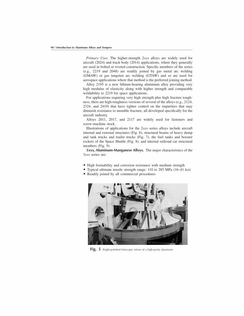
Primary Uses. The higher-strength 2xxx alloys are widely used foraircraft (2024) and truck body (2014) applications, where they generallyare used in bolted or riveted construction. Specific members of the series(e.g., 2219 and 2048) are readily joined by gas metal arc welding(GMAW) or gas tungsten arc welding (GTAW) and so are used foraerospace applications where that method is the preferred joining method.
Alloy 2195 is a new lithium-bearing aluminum alloy providing veryhigh modulus of elasticity along with higher strength and comparableweldability to 2219 for space applications.
For applications requiring very high strength plus high fracture tough-ness, there are high-toughness versions of several of the alloys (e.g., 2124,2324, and 2419) that have tighter control on the impurities that maydiminish resistance to unstable fracture, all developed specifically for theaircraft industry.
Alloys 2011, 2017, and 2117 are widely used for fasteners andscrew-machine stock.
Illustrations of applications for the 2xxx series alloys include aircraftinternal and external structures (Fig. 6), structural beams of heavy dumpand tank trucks and trailer trucks (Fig. 7), the fuel tanks and boosterrockets of the Space Shuttle (Fig. 8), and internal railroad car structuralmembers (Fig. 9).
3xxx, Aluminum-Manganese Alloys. The major characteristics of the3xxx series are:
O High formability and corrosion resistance with medium strengthO Typical ultimate tensile strength range: 110 to 285 MPa (16–41 ksi)O Readily joined by all commercial procedures
Fig. 5 Bright-polished telescopic mirror of a high-purity aluminum
90 / Introduction to Aluminum Alloys and Tempers
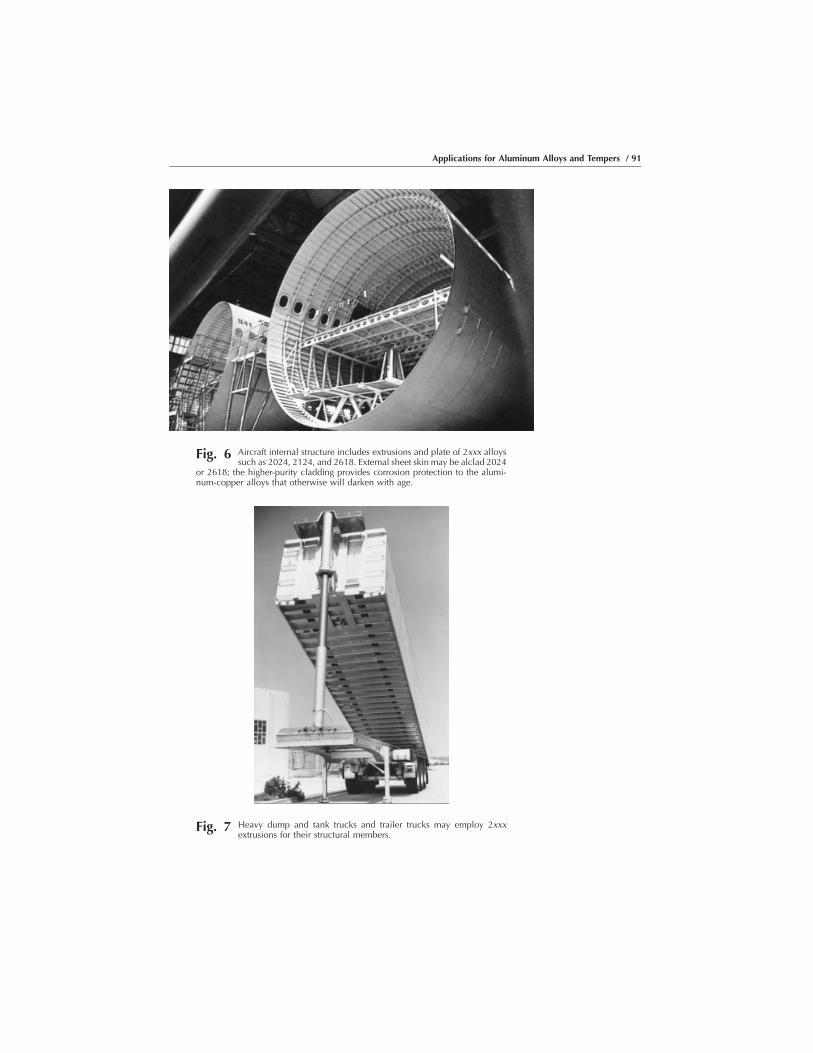
Fig. 6 Aircraft internal structure includes extrusions and plate of 2xxx alloyssuch as 2024, 2124, and 2618. External sheet skin may be alclad 2024
or 2618; the higher-purity cladding provides corrosion protection to the alumi-num-copper alloys that otherwise will darken with age.
Fig. 7 Heavy dump and tank trucks and trailer trucks may employ 2xxxextrusions for their structural members.
Applications for Aluminum Alloys and Tempers / 91

(a)
(b)
Fig. 8 (a) The booster rockets and (b) fuel tanks of the Space Shuttle are 2xxxalloys, originally 2219 and 2419; now sometimes aluminum-lithium
“Weldalite” alloy 2195
92 / Introduction to Aluminum Alloys and Tempers

The 3xxx series of alloys are strain hardenable, have excellent corrosionresistance, and are readily welded, brazed, and soldered.
Primary Uses. Alloy 3003 is widely used in cooking utensils andchemical equipment because of its superiority in handling many foodsand chemicals, and in builders’ hardware because of its superior corrosionresistance. Alloy 3105 is a principal for roofing and siding.
Because of the ease and flexibility of joining, 3003 and other membersof the 3xxx series are widely used in sheet and tubular form for heatexchangers in vehicles and power plants.
Alloy 3004 and its modification 3104 are the principals for the bodiesof drawn and ironed can bodies for beverage cans for beer and soft drinks.As a result, they are among the most used individual alloys in thealuminum system, in excess of 1.6 billion kg (3.5 billion lb) per year.
Typical applications of the 3xxx alloy series include automotive radiatorheat exchangers (Fig. 10) and tubing in commercial power plant heatexchangers (Fig. 11). In addition, the bodies of beverage cans (Fig. 12)are alloys 3004 or 3104, making it the largest volume alloy combinationin the industry.
4xxx, Aluminum-Silicon Alloys. The major characteristics of the4xxx series are:
O Heat treatableO Good flow characteristics, medium strengthO Typical ultimate tensile strength range: 175 to 380 MPa (25–55 ksi)O Easily joined, especially by brazing and soldering
Primary Uses. There are two major uses of the 4xxx series, bothgenerated by the excellent flow characteristics provided by relatively high
Fig. 9 Internal railroad car structural members are sometimes 2xxx alloys(also sometimes 6xxx alloys).
Applications for Aluminum Alloys and Tempers / 93
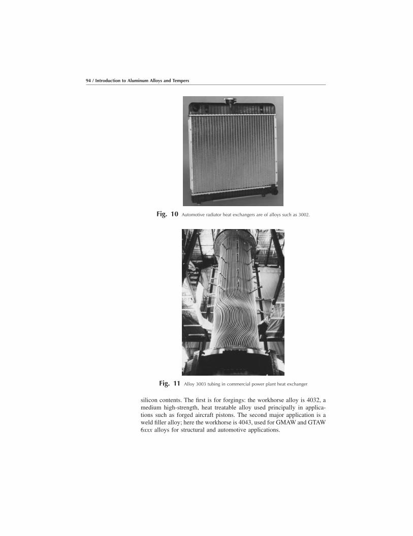
silicon contents. The first is for forgings: the workhorse alloy is 4032, amedium high-strength, heat treatable alloy used principally in applica-tions such as forged aircraft pistons. The second major application is aweld filler alloy; here the workhorse is 4043, used for GMAW and GTAW6xxx alloys for structural and automotive applications.
Fig. 10 Automotive radiator heat exchangers are of alloys such as 3002.
Fig. 11 Alloy 3003 tubing in commercial power plant heat exchanger
94 / Introduction to Aluminum Alloys and Tempers

As noted, the same characteristic—good flow provided by the highsilicon content—leads to both types of application. In the case of forgings,this good flow ensures the complete and precise filling of complex dies;in the case of welding, it ensures complete filling of grooves in themembers to be joined. For the same reason, other variations of the 4xxxalloys are used for the cladding on brazing sheet, the component thatflows to complete the bond.
Figure 13 illustrates a refrigerator coolant circulation system in a brazedunit of a high-silicon brazing alloy sheet. Alloy 4043 is one of the mostwidely used weld wires used in applications such as the automatedwelding of an auto body structure illustrated in Fig. 14.
5xxx, Aluminum-Magnesium Alloys. The major characteristics ofthe 6xxx series are:
Fig. 12 The bodies of beverage cans are alloys 3004 or 3104, making it thelargest volume alloy combination in the industry.
Fig. 13 Refrigerator coolant circulation system in brazed unit of high-siliconbrazing alloy sheet
Applications for Aluminum Alloys and Tempers / 95

O Strain hardenableO Excellent corrosion resistance, toughness, weldability; moderate
strengthO Building and construction, automotive, cryogenic, and marine appli-
cationsO Representative alloys: 5052, 5083, and 5754O Typical ultimate tensile strength range: 125 to 350 MPa (18–51 ksi)
Aluminum-magnesium alloys of the 5xxx series are strain hardenable andhave moderately high strength, excellent corrosion resistance even in saltwater, and very high toughness even at cryogenic temperatures to nearabsolute zero. They are readily welded by a variety of techniques, even atthicknesses up to 20 cm (8 in.).
Primary Use. As a result, 5xxx alloys find wide application in buildingand construction; highway structures, including bridges, storage tanks,and pressure vessels; cryogenic tankage and systems for temperatures aslow as –270 °C (�455 °F) or near absolute zero, and marine applications.
Alloys 5052, 5086, and 5083 are the workhorses from the structuralstandpoint, with increasingly higher strength associated with the increas-ingly higher magnesium content. Specialty alloys in the group include5182, the beverage can end alloy and, thus, among the largest in tonnage;5754 for automotive body panel and frame applications; and 5252, 5457,and 5657 for bright trim applications, including automotive trim.
Care must be taken to avoid use of 5xxx alloys with more than 3% Mgcontent in applications where they receive continuous exposure totemperatures above 100 °C (212 °F). Such alloys may become sensitizedand susceptible to SCC. For this reason, alloys such as 5454 and 5754 arerecommended for applications where high temperature exposure is likely.
Fig. 14 Alloy 4043 is one of the most widely used weld wires used inapplications such as this automated welding of an auto body
structure.
96 / Introduction to Aluminum Alloys and Tempers
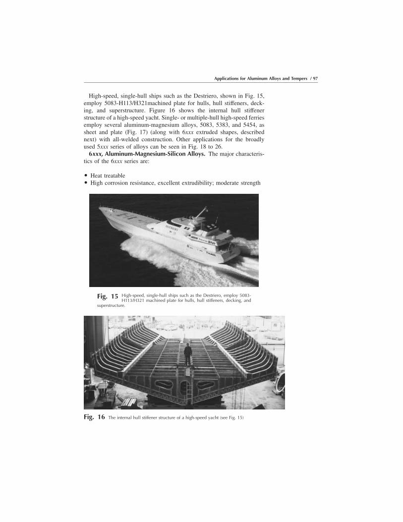
High-speed, single-hull ships such as the Destriero, shown in Fig. 15,employ 5083-H113/H321machined plate for hulls, hull stiffeners, deck-ing, and superstructure. Figure 16 shows the internal hull stiffenerstructure of a high-speed yacht. Single- or multiple-hull high-speed ferriesemploy several aluminum-magnesium alloys, 5083, 5383, and 5454, assheet and plate (Fig. 17) (along with 6xxx extruded shapes, describednext) with all-welded construction. Other applications for the broadlyused 5xxx series of alloys can be seen in Fig. 18 to 26.
6xxx, Aluminum-Magnesium-Silicon Alloys. The major characteris-tics of the 6xxx series are:
O Heat treatableO High corrosion resistance, excellent extrudibility; moderate strength
Fig. 15 High-speed, single-hull ships such as the Destriero, employ 5083-H113/H321 machined plate for hulls, hull stiffeners, decking, and
superstructure.
Fig. 16 The internal hull stiffener structure of a high-speed yacht (see Fig. 15)
Applications for Aluminum Alloys and Tempers / 97

O Typical ultimate tensile strength range: 125 to 400 MPa (18–58 ksi)O Readily welded by GMAW and GTAW methods
The 6xxx alloys are heat treatable and have moderately high strengthcoupled with excellent corrosion resistance. A unique feature is their greatextrudability, making it possible to produce in single shapes relativelycomplex architectural forms, as well as to design shapes that put themajority of the metal where it will most efficiently carry the highesttensile and compressive stresses. This feature is a particularly importantadvantage for architectural and structural members where stiffness-criticality is important.
Primary Use. Alloy 6063 is perhaps the most widely used because of itsextrudability; it is not only the first choice for many architectural andstructural members, but it has been the choice for the Audi automotivespace frame members. A good example of its structural use was theall-aluminum bridge structure in Foresmo, Norway (Fig. 26); it wasprefabricated in a shop and erected on the site in only a few days.
Fig. 17 Single- or multiple-hull high-speed ferries employ several alumi-num-magnesium alloys�5083, 5383, and 5454�as sheet and plate
(along with 6xxx extruded shapes) with all-welded construction.
98 / Introduction to Aluminum Alloys and Tempers

Higher-strength alloy 6061 extrusions and plate find broad use in weldedstructural members such as truck and marine frames, railroad cars, andpipelines.
Among specialty alloys in the series: 6066-T6, with high strength forforgings; 6070 for the highest strength available in 6xxx extrusions; and6101and 6201 for high-strength electrical bus and electrical conductorwire, respectively.
Fig. 18 Alloy 5083 was the workhorse for the 32 m (125 ft) diam spheres forshipboard transport of liquefied natural gas; the all-welded construc-
tion was 200 mm (8 in.) thick at the horizontal diam.
Fig. 19 The superstructure of many ocean liners, ferries, and most navalships is of welded 5xxx alloy construction, providing lightweight
and excellent corrosion resistance.
Applications for Aluminum Alloys and Tempers / 99

Figure 27 shows that the power of extruded aluminum-magnesium-silicon alloys is the “put-the-metal-where-you need-it” flexibility thesealloys and the extrusion process provide.
Some of the other most important applications for aluminum-magne-sium-silicon are in the structural members of wide-span roof structuresfor arenas and gymnasiums shown in Fig. 28; geodesic domes, such as theone made originally to house the Spruce Goose, the famous Hugheswooden flying boat, in Long Beach, CA, the largest geodesic dome everconstructed, at 250 m (1000 ft) across, 100 m (400 ft) high (Fig. 29); anintegrally stiffened bridge deck shape, used to produce replacementbridge decks, readily put in the roadway in hours (Fig. 30, 31); and amagnetic levitation (Mag-Lev) train in development in Europe and Japan
Fig. 20 Rugged coal cars are provided by welded 5454 alloy plate construc-tion.
Fig. 21 The demands of the superstructures of offshore oil rigs in highhumidity and water exposure are met with 5454, 5086, and 5083
aluminum-magnesium alloy welded construction.
100 / Introduction to Aluminum Alloys and Tempers

(Fig. 32). In addition, aluminum light poles are widely used around theworld for their corrosion resistance and crash protection systems provid-ing safety for auto drivers and passengers, as shown in Fig. 33.Representative important applications of the 6xxx alloy series in automo-bile structures are shown in Fig. 34 to 36.
Fig. 22 Automotive structures are likely to employ increasing amounts of 5754-O formed sheet for parts such asinternal door stiffeners or the entire body-in-white.
Fig. 23 Aluminum cans have ends of alloy 5182, making that one of thelargest volume alloys in production.
Applications for Aluminum Alloys and Tempers / 101

7xxx, Aluminum-Zinc Alloys. The major characteristics of the 7xxxseries are:
O Heat treatableO Very high strength; special high-toughness versionsO Typical ultimate tensile strength range: 220 to 610 MPa (32–88 ksi)O Mechanically joined
Fig. 24 5xxx alloys are commonly used as external facing sheets of com-posite aluminum-plastic structural panels, as in this Alusuisse Alu-
coban example.
Fig. 25 Sheet of 5xxx alloys often forms the surface of geodesic domestructures, as in this example of a water treatment plant.
102 / Introduction to Aluminum Alloys and Tempers

The 7xxx alloys are heat treatable and, among the aluminum-zinc-magnesium-copper versions in particular, provide the highest strengths ofall aluminum alloys. These alloys are not considered weldable bycommercial processes and are regularly used with riveted construction.
Primary Use. The widest application of the 7xxx alloys historically hasbeen in the aircraft industry, where fracture-critical design concepts have
Fig. 26 The Foresmo Bridge in northern Norway is an excellent example ofthe use of aluminum-magnesium alloys for built-up girders systems;
this photograph illustrates a major advantage of replacement aluminumbridges�the ability to prefabricate the spans and move them in place quickly,minimizing the disruption to traffic.
Fig. 27 The power of extruded aluminum-magnesium-silicon alloys is the“put-in-the metal-where-you-need-it” flexibility these alloys and the
extrusion process provide.
Applications for Aluminum Alloys and Tempers / 103

provided the impetus for the high-toughness alloy development. There areseveral alloys in the series that are produced especially for their hightoughness, notably 7150, 7175, and 7475; for these alloys, controlledimpurity levels, particularly of iron and silicon, maximize the combina-tion of strength and fracture toughness.
The atmospheric corrosion resistance of the 7xxx alloys is not as highas that of the 5xxx and 6xxx alloys, thus, in such service, they usually arecoated or, for sheet and plate, used in an alclad version. Also, specialtempers have been developed to improve their resistance to exfoliation
Fig. 28 The structural members of wide-span roof structures for arenas andgymnasiums are usually 6063 or 6061 extruded tube or beams,
covered with 5xxx alloy sheet.
104 / Introduction to Aluminum Alloys and Tempers
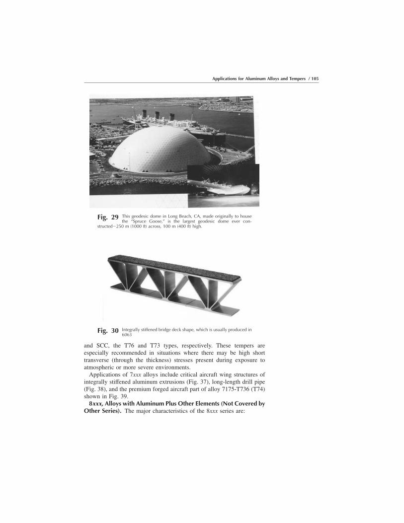
and SCC, the T76 and T73 types, respectively. These tempers areespecially recommended in situations where there may be high shorttransverse (through the thickness) stresses present during exposure toatmospheric or more severe environments.
Applications of 7xxx alloys include critical aircraft wing structures ofintegrally stiffened aluminum extrusions (Fig. 37), long-length drill pipe(Fig. 38), and the premium forged aircraft part of alloy 7175-T736 (T74)shown in Fig. 39.
8xxx, Alloys with Aluminum Plus Other Elements (Not Covered byOther Series). The major characteristics of the 8xxx series are:
Fig. 29 This geodesic dome in Long Beach, CA, made originally to housethe “Spruce Goose,” is the largest geodesic dome ever con-
structed�250 m (1000 ft) across, 100 m (400 ft) high.
Fig. 30 Integrally stiffened bridge deck shape, which is usually produced in6063
Applications for Aluminum Alloys and Tempers / 105
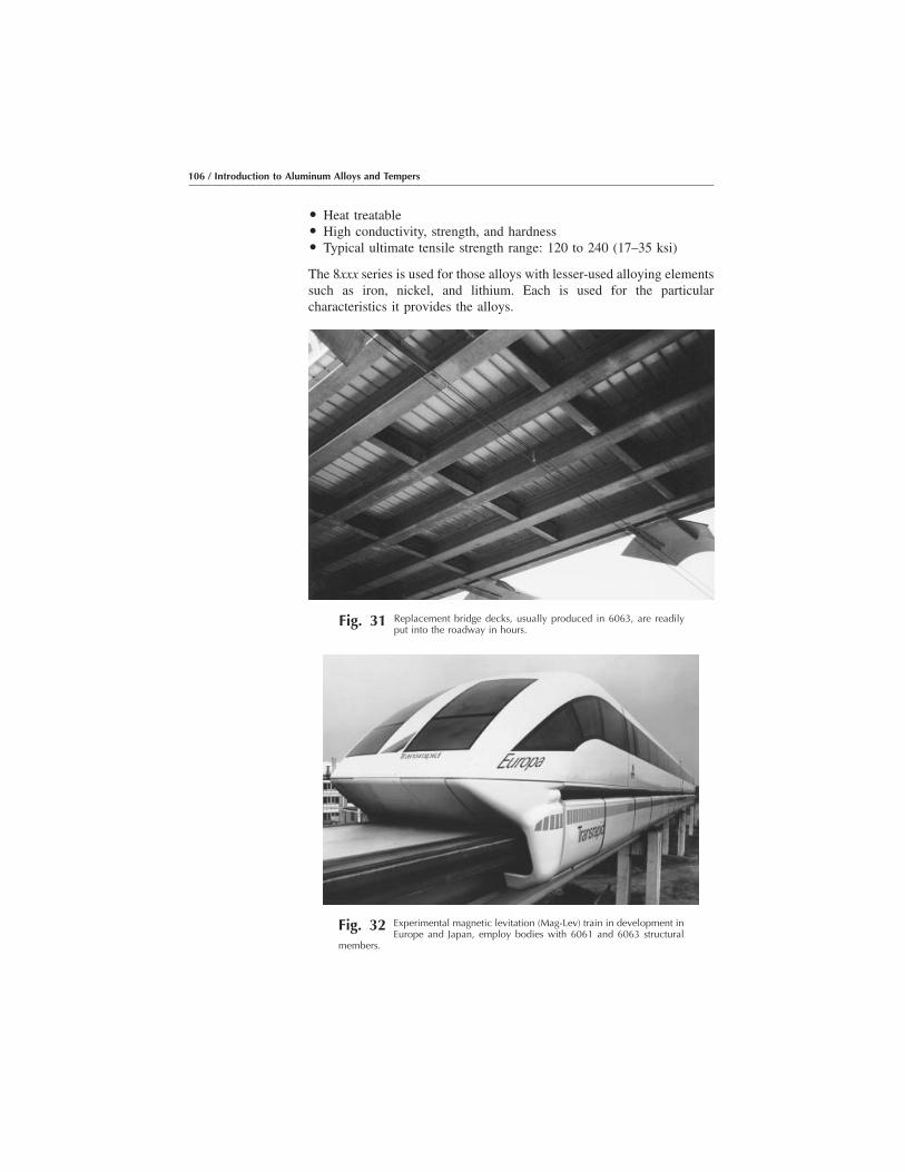
O Heat treatableO High conductivity, strength, and hardnessO Typical ultimate tensile strength range: 120 to 240 (17–35 ksi)
The 8xxx series is used for those alloys with lesser-used alloying elementssuch as iron, nickel, and lithium. Each is used for the particularcharacteristics it provides the alloys.
Fig. 31 Replacement bridge decks, usually produced in 6063, are readilyput into the roadway in hours.
Fig. 32 Experimental magnetic levitation (Mag-Lev) train in development inEurope and Japan, employ bodies with 6061 and 6063 structural
members.
106 / Introduction to Aluminum Alloys and Tempers
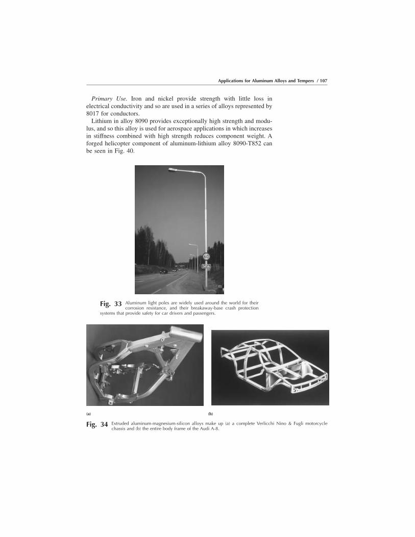
Primary Use. Iron and nickel provide strength with little loss inelectrical conductivity and so are used in a series of alloys represented by8017 for conductors.
Lithium in alloy 8090 provides exceptionally high strength and modu-lus, and so this alloy is used for aerospace applications in which increasesin stiffness combined with high strength reduces component weight. Aforged helicopter component of aluminum-lithium alloy 8090-T852 canbe seen in Fig. 40.
Fig. 33 Aluminum light poles are widely used around the world for theircorrosion resistance, and their breakaway-base crash protection
systems that provide safety for car drivers and passengers.
(a) (b)
Fig. 34 Extruded aluminum-magnesium-silicon alloys make up (a) a complete Verlicchi Nino & Fugli motorcyclechassis and (b) the entire body frame of the Audi A-8.
Applications for Aluminum Alloys and Tempers / 107

Cast AlloysIn comparison with wrought alloys, casting alloys contain larger
proportions of alloying elements such as silicon and copper, which resultsin a largely heterogeneous cast structure (i.e., one having a substantialvolume of second phases). This second phase material warrants carefulstudy, since any coarse, sharp, and brittle constituent can create harmfulinternal notches and nucleate cracks when the component is later putunder load. The fatigue properties are very sensitive to large heterogene-ities. As is shown later, good metallurgical and foundry practices canlargely prevent such defects.
The elongation and strength, especially in fatigue, of most cast productsare relatively lower than those of wrought products. This is becausecurrent casting practice is as yet unable to reliably prevent casting defects.In recent years, however, innovations in casting processes such as squeeze
Fig. 35 Welded 6063 extrusions combined with 5083 tube and 357 castingmake up the axle body assembly for the BMW Model 5.
Fig. 36 The General Motors Aurora, like many other production automo-biles, has aluminum closure panels of alloy 6111-T4.
108 / Introduction to Aluminum Alloys and Tempers
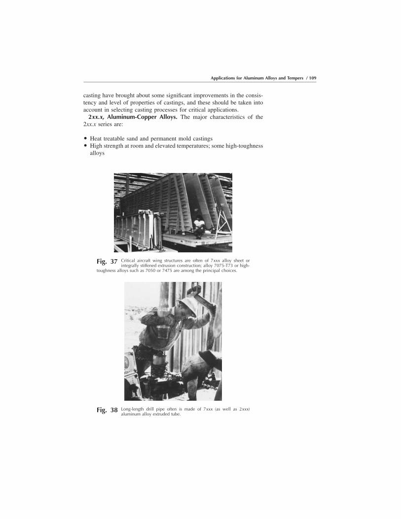
casting have brought about some significant improvements in the consis-tency and level of properties of castings, and these should be taken intoaccount in selecting casting processes for critical applications.
2xx.x, Aluminum-Copper Alloys. The major characteristics of the2xx.x series are:
O Heat treatable sand and permanent mold castingsO High strength at room and elevated temperatures; some high-toughness
alloys
Fig. 37 Critical aircraft wing structures are often of 7xxx alloy sheet orintegrally stiffened extrusion construction; alloy 7075-T73 or high-
toughness alloys such as 7050 or 7475 are among the principal choices.
Fig. 38 Long-length drill pipe often is made of 7xxx (as well as 2xxx)aluminum alloy extruded tube.
Applications for Aluminum Alloys and Tempers / 109

O Approximate ultimate tensile strength range: 130 to 450 MPa (20–65ksi)
Primary Use. The strongest of the common casting alloys is heat treated201.0, which has found important application in the aerospace industry.The castability of the alloy is somewhat limited by a tendency tomicroporosity and hot tearing so that it is best suited to investmentcasting. Its high toughness makes it particularly suitable for highlystressed components in machine tool construction, in electrical engineer-ing (pressurized switchgear castings), and in aircraft construction.
Fig. 39 An example of a premium forged aircraft part of alloy 7175-T736(T74)
Fig. 40 A forged helicopter component of aluminum-lithium alloy 8090-T852
110 / Introduction to Aluminum Alloys and Tempers
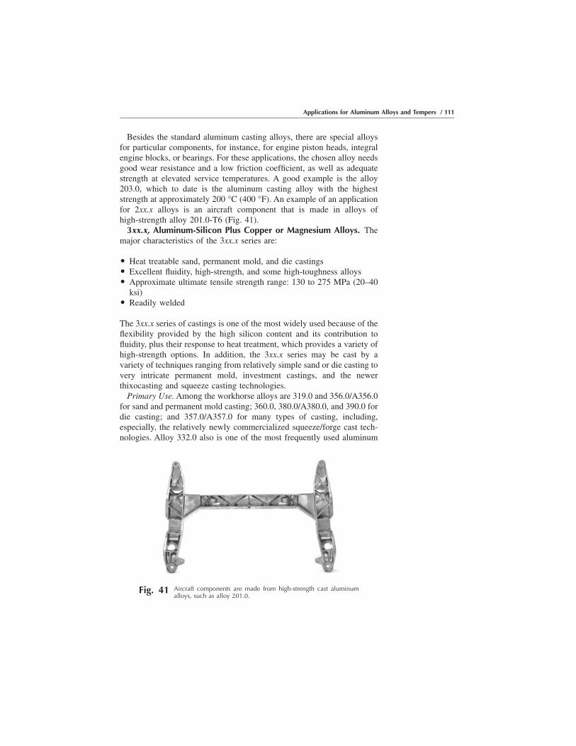
Besides the standard aluminum casting alloys, there are special alloysfor particular components, for instance, for engine piston heads, integralengine blocks, or bearings. For these applications, the chosen alloy needsgood wear resistance and a low friction coefficient, as well as adequatestrength at elevated service temperatures. A good example is the alloy203.0, which to date is the aluminum casting alloy with the higheststrength at approximately 200 °C (400 °F). An example of an applicationfor 2xx.x alloys is an aircraft component that is made in alloys ofhigh-strength alloy 201.0-T6 (Fig. 41).
3xx.x, Aluminum-Silicon Plus Copper or Magnesium Alloys. Themajor characteristics of the 3xx.x series are:
O Heat treatable sand, permanent mold, and die castingsO Excellent fluidity, high-strength, and some high-toughness alloysO Approximate ultimate tensile strength range: 130 to 275 MPa (20–40
ksi)O Readily welded
The 3xx.x series of castings is one of the most widely used because of theflexibility provided by the high silicon content and its contribution tofluidity, plus their response to heat treatment, which provides a variety ofhigh-strength options. In addition, the 3xx.x series may be cast by avariety of techniques ranging from relatively simple sand or die casting tovery intricate permanent mold, investment castings, and the newerthixocasting and squeeze casting technologies.
Primary Use. Among the workhorse alloys are 319.0 and 356.0/A356.0for sand and permanent mold casting; 360.0, 380.0/A380.0, and 390.0 fordie casting; and 357.0/A357.0 for many types of casting, including,especially, the relatively newly commercialized squeeze/forge cast tech-nologies. Alloy 332.0 also is one of the most frequently used aluminum
Fig. 41 Aircraft components are made from high-strength cast aluminumalloys, such as alloy 201.0.
Applications for Aluminum Alloys and Tempers / 111

casting alloys because it can be made almost exclusively from recycledscrap.
Among the illustrative applications are the thixoformed A356.0-T6inner turbo frame for the Airbus family of aircraft (Fig. 42); the gearboxcasing for a passenger car in alloy pressure die cast 380.0 shown in Fig.43; rear axle housing (Fig. 44); complex 3xx.x castings made by theinvestment casting processes, providing the ability to obtain exceptionallyintricate detail and fine quality (Fig. 45); and A356.0 cast wheels, whichare widely used in the U.S. automotive industry (Fig. 46).
4xx.x, Aluminum-Silicon Alloys. The major characteristics of the4xx.x series are:
O Non-heat-treatable sand, permanent mold, and die castingsO Excellent fluidity, good for intricate castingsO Approximate ultimate tensile strength range: 120 to 175 MPa (17–25
ksi)
Alloy B413.0 is notable for its very good castability and excellentweldability, which are due to its eutectic composition and low meltingpoint of 700 °C (1292 °F). It combines moderate strength with highelongation before rupture and good corrosion resistance. The alloy isparticularly suitable for intricate, thin-walled, leak-proof, fatigue-resistantcastings.
Primary Use. These alloys have found applications in relativelycomplex cast parts for typewriter and computer housings and dentalequipment, and also for fairly critical components in marine andarchitectural applications.
5xx.x, Aluminum-Magnesium Alloys. The major characteristics ofthe 5xx.x series are:
Fig. 42 Thixoformed A356.0-T6 inner turbo frame for the Airbus family ofaircraft
112 / Introduction to Aluminum Alloys and Tempers

O Non-heat-treatable sand, permanent mold, and die castingsO Tougher to cast; provides good finishing characteristicsO Excellent corrosion resistance, machinability, and surface appearanceO Approximate ultimate tensile strength range: 120 to 175 MPa (17–25
ksi)
The common feature of this group of alloys is good resistance tocorrosion.
Primary Use. Alloys 512.0 and 514.0 have medium strength and goodelongation and are suitable for components exposed to seawater or to
Fig. 43 Gearbox casting for a passenger car, in alloy pressure die cast 380.0
Fig. 44 Rear axle housing of 380.0 sand casting
Applications for Aluminum Alloys and Tempers / 113
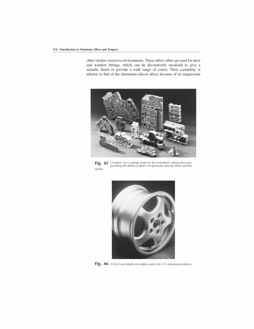
other similar corrosive environments. These alloys often are used for doorand window fittings, which can be decoratively anodized to give ametallic finish or provide a wide range of colors. Their castability isinferior to that of the aluminum-silicon alloys because of its magnesium
Fig. 45 Complex 3xx.x castings made by the investment casting processes,providing the ability to obtain exceptionally intricate detail and fine
quality
Fig. 46 A356.0 cast wheels are widely used in the U.S. automotive industry.
114 / Introduction to Aluminum Alloys and Tempers

content and, consequently, long freezing range. For this reason, it tends tobe replaced by 355.0, which has long been used for similar applications.
For die castings where decorative anodizing is particularly important,alloy 520.0 is quite suitable.
7xx.x, Aluminum-Zinc Alloys. The major characteristics of the 7xx.xseries are:
O Heat treatable sand and permanent mold castings (harder to cast)O Excellent machinability and appearanceO Approximate ultimate tensile strength range: 210 to 380 MPa (30–55
ksi)
Primary Use. Because of the increased difficulty in casting 7xx.x alloys,they tend to be used only where the excellent finishing characteristics andmachinability are important. Representative applications include furni-ture, garden tools, office machines, and farming and mining equipment.
8xx.x, Aluminum-Tin Alloys. The major characteristics of the 8xx.xseries are:
O Heat treatable sand and permanent mold castings (harder to cast)O Excellent machinabilityO Bearings and bushings of all typesO Approximate ultimate tensile strength range: 105 to 210 MPa (15–30
ksi)
Primary Use. As with the 7xx.x alloys, 8xx.x alloys are relatively hardto cast and tend to be used only where their combination of superiorsurface finish and relative hardness are important. The prime example isfor parts requiring extensive machining and for bushings and bearings.
Applications by Market Area
In the paragraphs that follow, a review is provided of the alloys oftenselected for products in a number of the major markets in whichaluminum is used.
Electrical Markets
The major products for which aluminum is used in electrical applica-tions are electric cable and bus conductors, where the high electricalconductivity (60% IACS) makes aluminum a cost-effective replacementfor copper products:
Applications for Aluminum Alloys and Tempers / 115
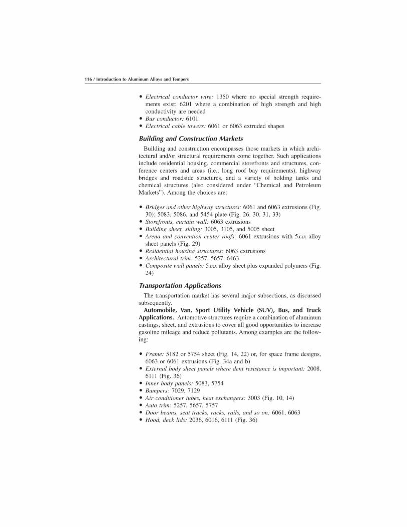
O Electrical conductor wire: 1350 where no special strength require-ments exist; 6201 where a combination of high strength and highconductivity are needed
O Bus conductor: 6101O Electrical cable towers: 6061 or 6063 extruded shapes
Building and Construction MarketsBuilding and construction encompasses those markets in which archi-
tectural and/or structural requirements come together. Such applicationsinclude residential housing, commercial storefronts and structures, con-ference centers and areas (i.e., long roof bay requirements), highwaybridges and roadside structures, and a variety of holding tanks andchemical structures (also considered under “Chemical and PetroleumMarkets”). Among the choices are:
O Bridges and other highway structures: 6061 and 6063 extrusions (Fig.30); 5083, 5086, and 5454 plate (Fig. 26, 30, 31, 33)
O Storefronts, curtain wall: 6063 extrusionsO Building sheet, siding: 3005, 3105, and 5005 sheetO Arena and convention center roofs: 6061 extrusions with 5xxx alloy
sheet panels (Fig. 29)O Residential housing structures: 6063 extrusionsO Architectural trim: 5257, 5657, 6463O Composite wall panels: 5xxx alloy sheet plus expanded polymers (Fig.
24)
Transportation ApplicationsThe transportation market has several major subsections, as discussed
subsequently.Automobile, Van, Sport Utility Vehicle (SUV), Bus, and Truck
Applications. Automotive structures require a combination of aluminumcastings, sheet, and extrusions to cover all good opportunities to increasegasoline mileage and reduce pollutants. Among examples are the follow-ing:
O Frame: 5182 or 5754 sheet (Fig. 14, 22) or, for space frame designs,6063 or 6061 extrusions (Fig. 34a and b)
O External body sheet panels where dent resistance is important: 2008,6111 (Fig. 36)
O Inner body panels: 5083, 5754O Bumpers: 7029, 7129O Air conditioner tubes, heat exchangers: 3003 (Fig. 10, 14)O Auto trim: 5257, 5657, 5757O Door beams, seat tracks, racks, rails, and so on: 6061, 6063O Hood, deck lids: 2036, 6016, 6111 (Fig. 36)
116 / Introduction to Aluminum Alloys and Tempers
O Truck beams: 2014, 6070 (Fig. 7)O Truck trailer bodies: 5456 (Fig. 7)O Wheels: A356.0 (Fig. 46) or formed 5xxx sheetO Housings, gear boxes: 357.0, A357.0 (Fig. 43, 44)
Aircraft and Aerospace Applications. Aircraft and aerospace appli-cations require high strength combined with, depending on the specificcomponent, high fracture toughness, high corrosion resistance, and/orhigh modulus (sometimes all three). The result has been a great numberof alloys and tempers developed specifically for this market, as illustratedby the examples below:
O Space mirror: High-purity aluminum (Fig. 5)O Wing and fuselage skin: 2024, alclad 2024, 7050 and 7475 sheet and
plate or extrusions (Fig. 6)O Wing structures: 2024, 2124, 2314, 7050 stiffened extrusions (Fig. 37)O Bulkhead: 2197, 7049, 7050, 7175O Rocket tankage: 2195, 2219, 2419 (Fig. 8a, b)O Engine components: 2618O Propellers: 2025O Rivets: 2117, 6053O If high modulus is critical: Lithium-bearing alloys 2090, 2091, 2195,
8090O If high fracture toughness is critical: 2124, 2224, 2324, 7050, 7175,
7475O For maximum fracture toughness: 7475O If stress-corrosion resistance is important: 7X50 or 7X75 in the
T73-type temperO If resistance to exfoliation attack is vital: 7xxx alloys in the T76-type
temperO For welded construction, as for shuttle tanks: 2219, 2195, 5456
Marine TransportationMany aluminum alloys readily withstand the corrosive attack of marine
salt water and so find applications in boats, ships, offshore stations, andother components that are immersed in saltwater:
O Hull material: 5083, 5383, 6061, 6063 (Fig. 15–17)O Superstructure: 5083, 5456 (Fig. 15)O Structural beams: 6061, 6063 (Fig. 16, 17)O Offshore stations, tanks: 5083, 5456 (Fig. 21)
Rail TransportationMuch as for automobile and truck bodies, aluminum lends itself to
railcar structural and exterior panel applications:
Applications for Aluminum Alloys and Tempers / 117
O Beams: 2014, 6061, 6070 (Fig. 9)O Exterior panels: 5456, 6111 (Fig. 9, 32)O Tank cars: 5083, 5454O Coal cars: 5083, 5454 (Fig. 20)O Cars for hot cargo: 5454 (Fig. 20)
Packaging ApplicationsPackaging applications require either great ductility and corrosion
resistance for foil and wrapping applications or great strength andworkability for rigid container sheet applications (i.e., cans). Alloychoices include:
O Aluminum foil for foods: 1175 (Fig. 2–4)O Rigid container (can) bodies: 3004 (Fig. 12)O Rigid container (can) ends: 5182 (Fig. 23)
Petroleum and Chemical Industry ComponentsThe excellent combination of high strength combined with superior
corrosion resistance plus weldability makes a number of aluminum alloysideal for chemical industry applications, even some involving verycorrosive fluids:
O Chemical piping: 1060, 5254, 6063O Pressure vessels (ASME Code): 5083, 5086, 6061, 6063O Pipelines: 6061, 6063, 6070O Cryogenic tankage: 5052, 5083, 5454, 6061, 6063 (Fig. 18)O Containers for hydrogen peroxide: 5254, 5652
Other MarketsWhile not major markets in themselves, a variety of specialty products
find great advantage in aluminum alloys:
O Screw machine products: 2011, 6262O Appliances: 5005, 5052O Tread plate: 6061O Weld wire: 4043 (for welding 6xxx alloys), 5356, 5183, 5556 (for
welding 5xxx alloys) (Fig. 14)
118 / Introduction to Aluminum Alloys and Tempers
CHAPTER 7RepresentativeMicrographs
A COMPILATION OF MICROGRAPHS illustrating the microstruc-ture of a wide range of aluminum alloys and tempers is a valuableadditional resource in understanding aluminum alloys and tempers.Therefore, micrographs of a number of representative alloys and tempersare shown in the following pages.
The reader should recognize that even within a single cross section ofa piece of plate, forging, extrusion, or casting, a considerable range ofmicrostructural features may be evident. Among different samples of asingle alloy, temper, and product, an even wider range of variations inmicrostructure will be evident. Thus, it should be clear that the micro-structures presented here are to be considered representative of therespective alloy, temper, and product but that not all other lots or even allother locations within these particular lots will look exactly like theexamples provided. Micrographs were taken mostly from Metallographyand Microstructures, Volume 9 of the ASM Handbook, ASM Interna-tional, 1985, pages 360 to 387. A few were taken from D.G. Altenpohl’sbook Aluminum: Technology, Applications and Environment (see Chapter8), courtesy of the Aluminum Association, Inc.
Introduction to Aluminum Alloys and TempersJ. Gilbert Kaufman, p119-184 DOI:10.1361/iaat2000p119
Copyright © 2000 ASM International® All rights reserved. www.asminternational.org

Wrought Aluminum Alloys
(a)
(b)
Fig. 1 99.99% high-purity aluminum as-cast. Transmission electron micro-graphs show subgrain structure in 99.99% 0.1 mm (0.004 in.) thick: (a)
hard rolled; (b) after recovery, 2 h at 150 °C (302 °F). 350�
Fig. 2 99.5% aluminum as-cast. Structure of 99.5% aluminum, DC case withgrain refiner. Grain size is smaller than 0.5 mm (0.02 in.); cell size is
from 50 to approximately 300 μm. The residual melt has solidified mainly in thecell boundaries.
120 / Introduction to Aluminum Alloys and Tempers

(a)
(b) (c)
Fig. 3 99.5% aluminum as-cast. (a) Coarse cell structure due to the solidification rate. Continuouscase 99.5% aluminum. Average cell size: 90 μm. (b) Fine cell structure. Normal
solidification rate. Average cell size: 60 μm. (c) Adjacent coarse and fine cells in direct chill (DC) cast99.5% aluminum. The coarse cells solidified relatively slowly and belong to a “floating crystal.”
(a) (b) (c) (d) (e) (f)
Fig. 4 Alloy 1100, various amounts of cold work. Recrystallized grain size as a function of coldwork. The following percentage numbers indicate the degree of cold work before
annealing: (a) 0%. (b) 2%. (c) 4%. (d) 6%. (e) 8%. (f) 10%.
Representative Micrographs / 121
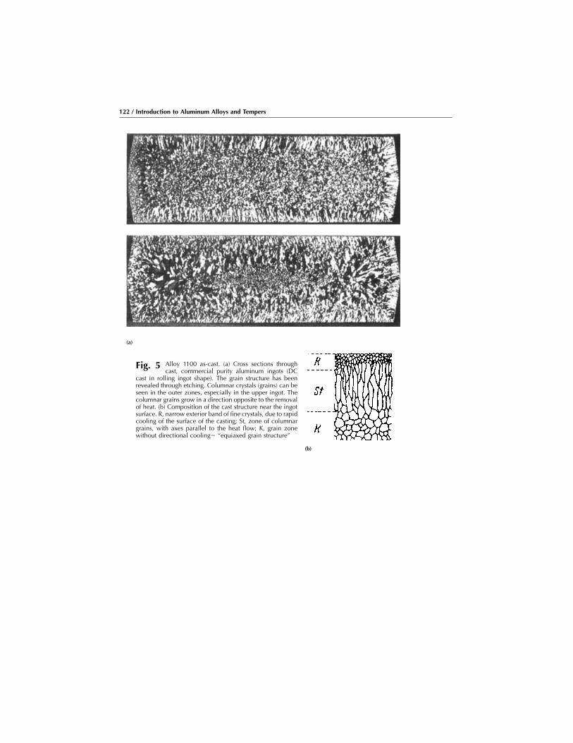
(a)
Fig. 5 Alloy 1100 as-cast. (a) Cross sections throughcast, commercial purity aluminum ingots (DC
cast in rolling ingot shape). The grain structure has beenrevealed through etching. Columnar crystals (grains) can beseen in the outer zones, especially in the upper ingot. Thecolumnar grains grow in a direction opposite to the removalof heat. (b) Composition of the cast structure near the ingotsurface. R, narrow exterior band of fine crystals, due to rapidcooling of the surface of the casting; St, zone of columnargrains, with axes parallel to the heat flow; K, grain zonewithout directional cooling� “equiaxed grain structure”
(b)
122 / Introduction to Aluminum Alloys and Tempers

Fig. 6 Alloy 1100-O sheet, cold rolled and an-nealed. Recrystallized, equiaxed grains, and
insoluble particles of FeAl3 (black). Size and distributionof FeAl3 in the worked structure were unaffected byannealing. See Fig. 7. 0.5% HF. 500�
Fig. 7 Alloy 1100-H18 sheet, cold rolled. Notemetal flow around insoluble particles of
FeAl3 (black). Particles are remnants of scriptlike con-stituents in the ingot that have been fragmented byworking. See Fig. 6. 0.5% HF. 500�
Fig. 8 Alloy 2014-T4 closed-die forging, solutionheat treated at 500 °C (935 °F) for 2 h and
quenched in water at 60 to 70 °C (140 to 160 °F).Longitudinal section. Structure contains particles ofCuAl2 (white, outlined) and insoluble (Fe,Mn)3SiAl12(dark). Keller’s reagent. 100�
Fig. 9 Alloy 2014-T6 closed-die forging, solutionheat treated, then aged at 170 °C (340 °F) for
10 h. Longitudinal section. Fragmented grain structurecontains particles of CuAl2 (white, outlined) and in-soluble (Fe,Mn)2SiAl12 (dark), but very fine particles ofCuAl2 have precipitated in the matrix. Keller’s reagent.100�
Representative Micrographs / 123

Fig. 10 Alloy 2014-T6 closed-die forging, over-aged. Solution heat treatment was suffi-
cient, but specimen was overaged. Fragmented grainstructure contains particles of CuAl2 (white, outlined)and insoluble (Fe,Mn)2SiAl12 (dark), but more CuAl2 hasprecipitated. Note lack of grain contrast. Keller’s re-agent. 100�
Fig. 11 Alloy 2014-T61 closed-die forging. Blisteron surface is associated with hydrogen po-
rosity. As-polished. 50�
Fig. 12 Alloy 2024-O plate, 13 mm (0.5 in.) thick,hot rolled and annealed. Longitudinal sec-
tion. Elongated recrystallized grains and unrecrystallizedstringers resulting from polygonization that occurredduring the hot water working. KMnO4, Na2CO3. 100�
Fig. 13 Alloy 2024-O sheet. Structure consists oflight gray particles of insoluble (Cu,Fe,
Mn)Al6 and fine particles of CuMgAl2 that precipitatedduring annealing. 25% HNO3. 500�
124 / Introduction to Aluminum Alloys and Tempers

Fig. 14 Alloy 2024-T3 sheet, solution heat treatedat 495 °C (920 °F) and quenched in cold
water. Longitudinal section. Dark particles are CuMgAl2,Cu2MnAl20, and Cu2FeAl7. See also Fig. 15. Keller’sreagent. 500�
Fig. 15 Alloy 2024-T3 sheet, solution heat treatedat 495 °C (920 °F) and quenched in boiling
water. The lower quenching rate resulted in precipita-tion of CuMgAl2 at grain boundaries. Keller’s reagent.500�
Fig. 16 Alloy 2024-T3 sheet, solution heat treatedat 495 °C (920 °F) and cooled in an air
blast. The lower cooling rate resulted in increasedprecipitation of CuMgAl2 at grain boundaries. Keller’sreagent. 500�
Fig. 17 Alloy 2024-T3 sheet, solution heat treatedat 495 °C (920 °F) and cooled in still air.
The slow cooling resulted in intragranular and grain-boundary precipitation of CuMgAl2. Keller’s reagent.500�
Representative Micrographs / 125

Fig. 18 Alloy 2024-T3 alclad, sheet clad with alloy1230 (5% per side), solution heat treated.
Normal amount of copper and magnesium diffusionfrom base metal into cladding (top). Keller’s reagent.100�
Fig. 19 Alloy 2024-T6 sheet, 6.4 mm (0.24 in.)thick (reduced from 406 mm, or 16 in.,
thick ingot), stretched 2%. Longitudinal section. Noteabsence of strain lines in structure. See also Fig. 20 and21. Keller’s reagent. 100�
Fig. 20 Alloy 2024-T6 sheet, 6.4 mm (0.24 in.)thick (reduced from 406 mm, or 16 in.,
thick ingot), stretched 6%. Longitudinal section. Somefaint strain lines have formed. See also Fig. 21. Keller’sreagent. 100�
Fig. 21 Alloy 2024-T6 sheet, 6.4 mm (0.24 in.)thick (reduced from 406 mm, or 16 in.,
thick ingot), stretched 20%. Longitudinal section. Manystrain lines have formed. See also Fig. 20. Keller’sreagent. 100�
126 / Introduction to Aluminum Alloys and Tempers

Fig. 22 Alloy 2024-T851 plate, 150 mm (6 in.)thick, cold rolled, solution heat treated,
stretched, and artificially aged. Section was taken in therolling plane (long transverse) from an area near thesurface showing elongated grains. Keller’s reagent.200�
Fig. 23 Alloy 2024-T851 plate, 150 mm (6 in.)thick, cold rolled, solution heat treated,
stretched, and artificially aged. Longitudinal sectionshowing the edge view of an area near the surface of theplate. Grains are flattened and elongated in the directionof rolling. See also Fig. 24. 200�
Fig. 24 Alloy 2024-T851 plate, 150 mm (6 in.)thick, cold rolled, solution heat treated,
stretched, and artificially aged. A short transverse sectionshowing the end view of an area near the surface of theplate. Grains are flattened but are not as elongated asgrains in Fig. 23. Keller’s reagent. 200�
Fig. 25 Alloy 2024-T851 plate, 150 mm (6 in.)thick, cold rolled, solution heat treated,
stretched, and artificially aged. Section was taken in therolling plane (long transverse) from the center of theplate thickness, which received less cold working thanthe surface. Keller’s reagent. 200�
Representative Micrographs / 127
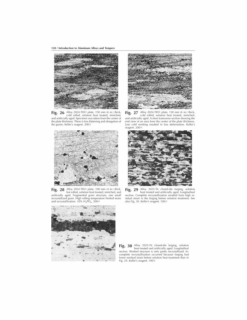
Fig. 26 Alloy 2024-T851 plate, 150 mm (6 in.) thick,cold rolled, solution heat treated, stretched,
and artificially aged. Specimen was taken from the center ofthe plate thickness. There is less flattening and elongation ofthe grains. Keller’s reagent. 200�
Fig. 27 Alloy 2024-T851 plate, 150 mm (6 in.) thick,cold rolled, solution heat treated, stretched,
and artificially aged. A short transverse section showing theend view of an area from the center of the plate thickness.Less cold working resulted in less deformation. Keller’sreagent. 200�
Fig. 28 Alloy 2024-T851 plate, 100 mm (4 in.) thick,hot rolled, solution heat treated, stretched, and
artificially aged. Fragmented grain structure, one smallrecrystallized grain. High rolling temperature limited strainand recrystallization. 10% H3PO4. 500�
Fig. 29 Alloy 2025-T6 closed-die forging, solutionheat treated and artificially aged. Longitudinal
section. Complete recrystallization resulted from high re-sidual strain in the forging before solution treatment. Seealso Fig. 30. Keller’s reagent. 100�
Fig. 30 Alloy 2025-T6 closed-die forging, solutionheat treated and artificially aged. Longitudinal
section. Worked structure is only partly recrystallized. In-complete recrystallization occurred because forging hadlower residual strain before solution heat treatment than inFig. 29. Keller’s reagent. 100�
128 / Introduction to Aluminum Alloys and Tempers
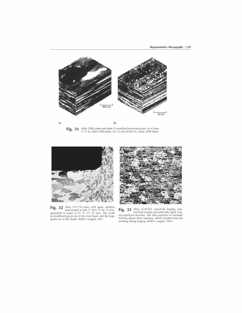
(a) (b)
Fig. 31 Alloy 2090, plate and sheet. Crystallized microstructures. (a) 45 mm(1.75 in.) thick 2090 plate. (b) 1.6 mm (0.063 in.) thick 2090 sheet.
Fig. 32 Alloy 2117-T4 rivet, cold upset, solutionheat treated at 500 °C (935 °F) for 35 min,
quenched in water at 25 °C (75 °F) max. The smallrecrystallized grains are in the rivet head, and the largegrains are in the shank. Keller’s reagent. 60�
Fig. 33 Alloy 2218-T61 closed-die forging, solu-tion heat treated and artificially aged. Fine,
recrystallized structure. The dark particles of insolubleFeNiAl9 phase show banding, which resulted from theworking during forging. Keller’s reagent. 100�
Representative Micrographs / 129

Fig. 34 Alloy 2219-T6 closed-die forging solutionheat treated and artificially aged. Longitu-
dinal section. Worked structure contains some recrystal-lized grains. See Fig. 35 for a totally unrecrystallizedstructure. Keller’s reagent. 100�
Fig. 35 Alloy 2219-T6 closed-die forging solutionheat treated and artificially aged. Longitu-
dinal section shows no recrystallization of the workedstructure. Note the large amount of slip (light parallellines) that has occurred on two sets of slip planes.Keller’s reagent. 100�
Fig. 36 Alloy 2618-T4 closed-die forging, solutionheat treated at 530 °C (985 °F) for 2 h,
quenched in boiling water. Small particles of CuMgAl2precipitated at grain boundaries; larger particles areinsoluble FeNiAl9 phase. 0.5% HF. 500�
Fig. 37 Alloy 2618-T4 forging, solution heattreated at 530 °C (985 °F) for 2 h and
cooled in still air. Small particles of CuMgAl2 precipi-tated at grain boundaries; larger particles are insolubleFeNiAl9 phase. Slower cooling resulted in an increase ofCuMgAl2 at grain boundaries and within grains. 0.5%HF. 500�
Fig. 38 Alloy 2618-T61 forging, solution heattreated, quenched in boiling water, aged at
200 °C (390 °F) for 20 h, stabilized at 230 °C (450 °F) for7 h. Small particles of CuMgAl2 precipitated at grainboundaries; larger particles are insoluble FeNiAl9 phase.CuMgAl2 also has precipitated in grains. 0.5% HF. 500�
Fig. 39 Alloy 2618-T61 forging, solution heattreated, cooled in still air, aged at 200 °C
(390 °F) for 20 h, stabilized at 230 °C (450 °F) for 7 h.Small particles of CuMgAl2 precipitated at grain bound-aries; larger particles are insoluble FeNiAl9 phase.CuMgAl2 also has precipitated in grains. Note increasein precipitation and alloy depletion near light grainboundaries. 0.5% HF. 500�
130 / Introduction to Aluminum Alloys and Tempers

(c)
Fig. 40 Alloy 3003 as-cast. (a) Structure of a DC cast rolling ingot. Angular precipitates of the aluminum-manganese-iron phase in the cast grains and at the grain boundaries. 860�. (b) Structure of a DC cast
rolling ingot heat-treated 72 h at 600 °C (1112 °F) then quenched. Through diffusion processes the precipitates havegrown and rounded off (spheroidized). 800�. (c) Structure of a DC cast rolling ingot heat-treated 6 h at 600 °C (1112°F), then furnace cooled for 15 h to 450 °C (842 °F). A fine AlMnFe precipitate originated from the supersaturatedsolid solution due to the slow cooling. At the same time, the precipitates from the cast structure spheroidized, lessthan in (b) due to the shorter heat treatment. 860�
Fig. 41 Alloy 3003-F hot rolled. Longitudinal sectionshows stringer of oxide from an inclusion in the
cast ingot and particles of phases that contain manganese,both primary (large, angular) and eutectic (small). As-polished. 500�
Fig. 42 Alloy 3003-O sheet, annealed. Longitudinalsection shows recrystallized grains. Grain
elongation indicates rolling direction, but not the crystallo-graphic orientation within each grain. Polarized light. Bark-er’s reagent. 100�
(a) (b)
Representative Micrographs / 131

Fig. 43 Alloy 3003-O sheet, annealed. Higher magni-fication of the longitudinal section shows re-
crystallized grains. Grain elongation indicates rolling direc-tion, but not the crystallographic orientation within eachgrain. Dispersion of insoluble particles of (Fe,Mn)Al6 (large)and aluminum-manganese-silicon (both large and small)was not changed by annealing. 0.5% HF. 750�
Fig. 44 Alloy 5083 plate, cold rolled. The coarse, grayareas are particles of insoluble (Fe,Mn)3Al12;
adjacent black areas are voids caused by breakup of thebrittle (Fe,Mn)3Al12 particles during cold rolling. Separateblack areas may be insoluble particles of Mg2Si. As-pol-ished. 500�
Fig. 45 Alloy 5083-H112 plate, cold rolled. Longitudi-nal section shows particles of primary MnAl6
(gray, outlined). Small, dark areas may be particles ofinsoluble phases, such as phases that contain magnesium(for example, Mg2Si) or that contain manganese. Keller’sreagent. 50�
132 / Introduction to Aluminum Alloys and Tempers
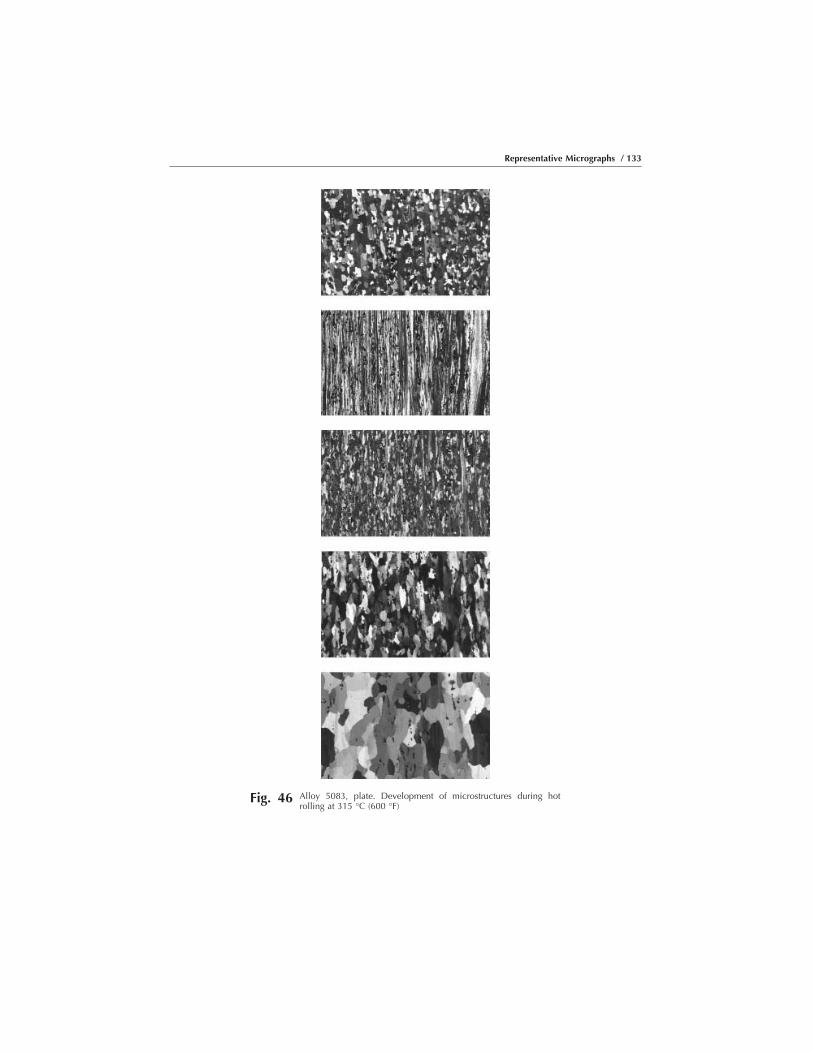
Fig. 46 Alloy 5083, plate. Development of microstructures during hotrolling at 315 °C (600 °F)
Representative Micrographs / 133

Fig. 47 Alloy 5086-H34 plate, 13 mm (0.5 in.)thick, cold rolled and stabilized at 120 to
175 °C (250 to 350 °F) to prevent age softening.Undesirable continuous network of Mg2Al3 particlesprecipitated at grain boundaries; large particles areinsoluble phases. See also Fig. 50. 25% HNO3. 250�
Fig. 48 Alloy 5454, hot-rolled slab, longitudinalsection. Oxide stringer from an inclusion in
the cast ingot. The structure also shows some particles of(Fe,Mn)Al6 (light gray). As-polished. 500�
Fig. 49 Alloy 5456 plate, hot rolled. Longitudinalsection. Polarized light. Partial recrystalli-
zation occurred immediately after hot rolling from re-sidual heat. This type of recrystallization is frequentlyreferred to as “dynamic recrystallization.” Barker’s re-agent. 100�
Fig. 50 Alloy 5456 plate, 6.4 mm (0.25 in.) thick,cold rolled and stress relieved below the
solvus at 245 °F (475 °F) . Particles are (Fe,Mn)Al6 (gray),Mg2Si (black), and Mg2Al3 (fine precipitate). In contrastto Fig. 47, there is no continuous network of precipitateat grain boundaries. 25% HNO3. 500�
134 / Introduction to Aluminum Alloys and Tempers

Fig. 51 Alloy 5456-O plate, 13 mm (0.5 in.) thick,hot rolled and annealed above the solvus.
Rapid cooling resulted in retention of Mg2Al3 in solidsolution. The light, outlined particles are insoluble(Fe,Mn)Al6; the dark particles are insoluble Mg2Si. 25%HNO3. 500�
Fig. 52 Alloy 5457-F extrusion. A transverse sec-tion, photographed with polarized light.
Surface grains (top) show random reflection, indicatingrandom crystallographic orientation; interior grainsshow uniform reflection, indicating a high degree ofpreferred orientation. Barker’s reagent. 100�
Fig. 53 Alloy 5457-F plate, 6.4 mm (0.25 in.) thick,hot rolled. Fine particles of Mg2Si precipi-
tated during the rolling. If carried through to final sheet,this amount of precipitate would cause an objectionablemilky appearance in a subsequently applied anodiccoating. 0.5% HF. 500�
Fig. 54 Alloy 5457-O plate, 10 mm (0.4 in.) thick,longitudinal section. Annealed at 345 °C
(650 °F). Polarized light. The grains are equiaxed. Seealso Fig. 55–57. Barker’s reagent. 100�
Representative Micrographs / 135

Fig. 55 Alloy 5457-O plate, originally 10 mm (0.4 in.)thick, annealed at 345 °C (650 °F). Effect of
cold rolling. Polarized light. See Fig. 56 for annealedstructure. 10% reduction. Barker’s reagent. 100�
Fig. 56 Alloy 5457-O plate, originally 10 mm (0.4 in.)thick, annealed at 345 °C (650 °F). Effect of
cold rolling. Polarized light. See Fig. 54 for annealedstructure. 40% reduction. Barker’s reagent. 100�
Fig. 57 Alloy 5457-O plate, originally 10 mm (0.4 in.)thick, annealed at 345 °C (650 °F). Effect of
cold rolling. Polarized light. See Fig. 54 for annealedstructure. 80% reduction. Barker’s reagent. 100�
Fig. 58 Alloy 5657 ingot. Dendritic segregation (cor-ing) of titanium. Black spots are etch pits.
Anodized coating from Barker’s reagent was stripped with10% H3PO4 at 80 °C (180 °F). 200�
Fig. 59 Alloy 5657-F sheet, cold rolled (85% reduc-tion). Longitudinal section. Polarized light.
Grains are greatly elongated and contribute to high strength,but ductility is lower than for specimen in Fig. 61. Barker’sreagent. 100�
Fig. 60 Alloy 5657-F sheet, cold rolled (85% reduc-tion). Stress relieved at 300 °C (575 °F) for 1 h.
Polarized light. Structure shows onset of recrystallization,which improves formability. Barker’s reagent. 100�

Fig. 61 Alloy 5657-F sheet, cold rolled (85% re-duction). Annealed at 315 °C (600 °F) for 1
h. Polarized light. Recrystallized grains and bands ofunrecrystallized grains. Barker’s reagent. 100�
Fig. 62 Alloy 5657 sheet. Banding from dendriticsegregation (coring) of titanium in the ingot
(see Fig. 58). Anodized coating from Barker’s reagentwas stripped with 10% H3PO4 at 80 °C (180 °F). 200�
Fig. 63 Alloy 6061-F plate, 38 mm (1.5 in.) thick,as hot rolled (91% reduction). Longitudinal
section from center of plate thickness. Particles areFe3SiAl12 (gray, scriptlike) and Mg2Si (black) See alsoFig. 64 and 65. 0.5% HF. 250�
Fig. 64 Alloy 6061-F plate, 38 mm (1.5 in.) thick,as hot rolled (91% reduction). Longitudinal
section from near plate surface. Particles of Fe3SiAl12and Mg2Si are more broken up and uniformly distributedthan in Fig. 63 (midthickness). See also Fig. 65. 0.5% HF.250�
Representative Micrographs / 137
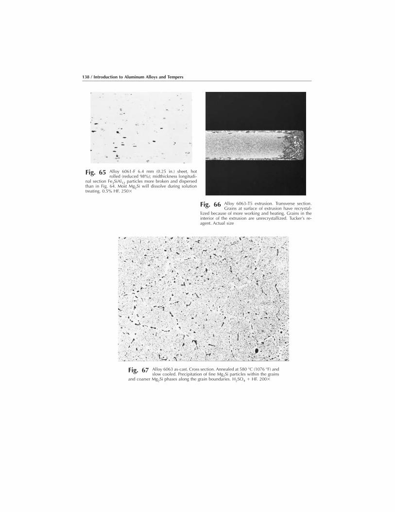
Fig. 65 Alloy 6061-F 6.4 mm (0.25 in.) sheet, hotrolled (reduced 98%); midthickness longitudi-
nal section Fe3SiAl12 particles more broken and dispersedthan in Fig. 64. Most Mg2Si will dissolve during solutiontreating. 0.5% HF. 250�
Fig. 66 Alloy 6063-T5 extrusion. Transverse section.Grains at surface of extrusion have recrystal-
lized because of more working and heating. Grains in theinterior of the extrusion are unrecrystallized. Tucker’s re-agent. Actual size
Fig. 67 Alloy 6063 as-cast. Cross section. Annealed at 580 °C (1076 °F) andslow cooled. Precipitation of fine Mg2Si particles within the grains
and coarser Mg2Si phases along the grain boundaries. H2SO4 � HF. 200�
138 / Introduction to Aluminum Alloys and Tempers

Fig. 68 Alloy 6063 extrusion. Longitudinal section. Cooled with agitated air.Metastable, oversaturated mixed crystal and primary phases aligned
along the direction of the deformation. H2SO4 � HF. 200�
Fig. 69 Alloy 6063 extrusion, artificially aged, air cooled. Cross sectionshowing coherent fine precipitates and primary phases in the grains
and coarser precipitates on the grain boundaries. H2SO4 � HF. 200�
Representative Micrographs / 139

Fig. 70 Alloy 6063, continuous casting. Cross section. Alloy segregation(coring) with areas of leftover molten material at the grain bound-
aries. Barker’s reagent. 50�
Fig. 71 Alloy 6063-T4, annealed at 580 °C (1076 °F) and water quenched.Cross section showing substantial removal of segregation and
absorption of the cast phases. Barker’s reagent. 50�
140 / Introduction to Aluminum Alloys and Tempers
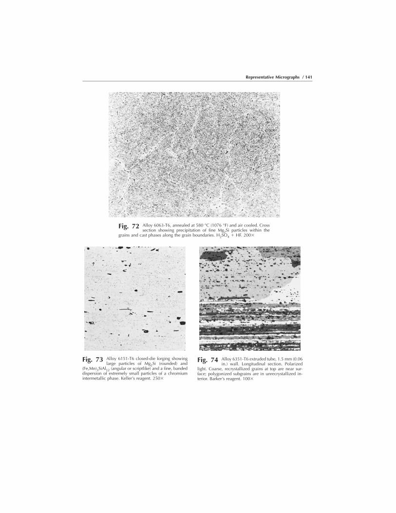
Fig. 72 Alloy 6063-T6, annealed at 580 °C (1076 °F) and air cooled. Crosssection showing precipitation of fine Mg2Si particles within the
grains and cast phases along the grain boundaries. H2SO4 � HF. 200�
Fig. 73 Alloy 6151-T6 closed-die forging showinglarge particles of Mg2Si (rounded) and
(Fe,Mn)3SiAl12 (angular or scriptlike) and a fine, bandeddispersion of extremely small particles of a chromiumintermetallic phase. Keller’s reagent. 250�
Fig. 74 Alloy 6351-T6 extruded tube, 1.5 mm (0.06in.) wall. Longitudinal section. Polarized
light. Coarse, recrystallized grains at top are near sur-face; polygonized subgrains are in unrecrystallized in-terior. Barker’s reagent. 100�
Representative Micrographs / 141
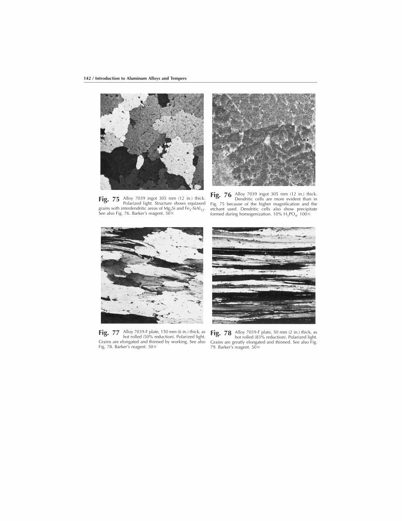
Fig. 75 Alloy 7039 ingot 305 mm (12 in.) thick.Polarized light. Structure shows equiaxed
grains with interdendritic areas of Mg2Si and Fe3-SiAl12.See also Fig. 76. Barker’s reagent. 50�
Fig. 76 Alloy 7039 ingot 305 mm (12 in.) thick.Dendritic cells are more evident than in
Fig. 75 because of the higher magnification and theetchant used. Dendritic cells also show precipitateformed during homogenization. 10% H3PO4. 100�
Fig. 77 Alloy 7039-F plate, 150 mm (6 in.) thick, ashot rolled (50% reduction). Polarized light.
Grains are elongated and thinned by working. See alsoFig. 78. Barker’s reagent. 50�
Fig. 78 Alloy 7039-F plate, 50 mm (2 in.) thick, ashot rolled (83% reduction). Polarized light.
Grains are greatly elongated and thinned. See also Fig.79. Barker’s reagent. 50�
142 / Introduction to Aluminum Alloys and Tempers

Fig. 79 Alloy 7039-F plate, 150 mm (6 in.) thick, ashot rolled (50% reduction). Dendritic cells
are elongated and thinned by working. See also Fig. 77.10% H3PO4. 100�
Fig. 80 Alloy 7039-F plate, 50 mm (2 in.) thick, ashot rolled (83% reduction). Dendritic cells
are elongated and thinned by working. See also Fig. 78.10% H3PO4. 100�
Fig. 81 Alloy 7075-O sheet, annealed. The fineparticles of MgZn2 (dark) were precipitated
at lower temperatures during heating to or cooling fromthe annealing temperature. The insoluble particles ofFeAl3 (light gray, outlined) were not affected by theannealing treatment. See also Fig. 82. 25% HNO3.500�
Fig. 82 Alloy 7075-O sheet, annealed, cooledmore slowly from annealing temperature
than specimen in Fig. 81. The fine particles of MgZn2(dark) were precipitated at lower temperatures duringheating to or cooling from the annealing temperature.The soluble particles of FeAl3 (light gray) were notaffected by the annealing treatment. Platelets of MgZn2precipitated at grain boundaries during slow cooling.25% HNO3. 500�
Representative Micrographs / 143
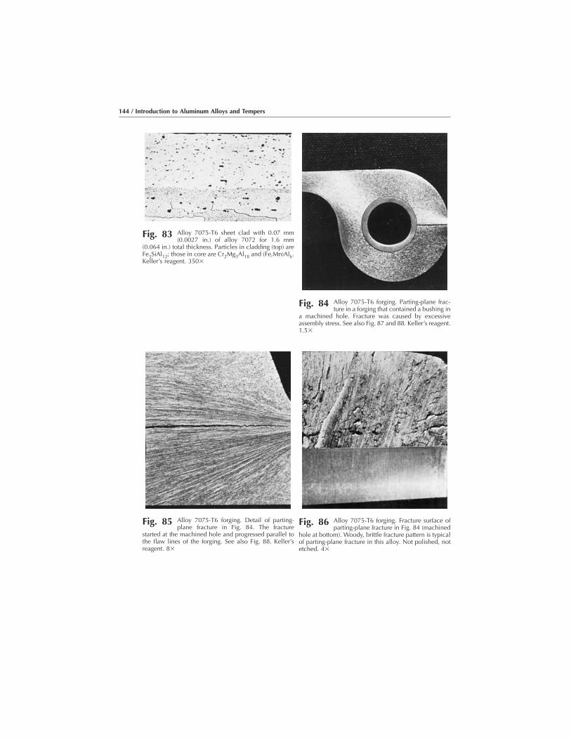
Fig. 83 Alloy 7075-T6 sheet clad with 0.07 mm(0.0027 in.) of alloy 7072 for 1.6 mm
(0.064 in.) total thickness. Particles in cladding (top) areFe3SiAl12; those in core are Cr2Mg3Al18 and (Fe,Mn)Al6.Keller’s reagent. 350�
Fig. 84 Alloy 7075-T6 forging. Parting-plane frac-ture in a forging that contained a bushing in
a machined hole. Fracture was caused by excessiveassembly stress. See also Fig. 87 and 88. Keller’s reagent.1.5�
Fig. 85 Alloy 7075-T6 forging. Detail of parting-plane fracture in Fig. 84. The fracture
started at the machined hole and progressed parallel tothe flaw lines of the forging. See also Fig. 88. Keller’sreagent. 8�
Fig. 86 Alloy 7075-T6 forging. Fracture surface ofparting-plane fracture in Fig. 84 (machined
hole at bottom). Woody, brittle fracture pattern is typicalof parting-plane fracture in this alloy. Not polished, notetched. 4�
144 / Introduction to Aluminum Alloys and Tempers

Fig. 87 Alloy 7075-T6 forging. Fold, or lap, at a machined fillet in a forging.Defect was continuous before machining. See also Fig. 88 for details
of a small area of the portion of the defect at lower right. Keller’s reagent. 8�
Fig. 88 Alloy 7075-T6 forging. Enlarged view of an area of the fold, or lap,at lower right in Fig. 87. Defect contains nonmetallic particles,
oxides, and voids, which prevented it from welding, or healing, during forging.Keller’s reagent. 200�
Fig. 89 Alloy 7075-T6 forging. Surface appearance of a lap (at trough,center). Forging flow lines bend in the vicinity of the lap, indicating
that the defect occurred during forging. See also Fig. 90. Not polished, notetched. 10�
Representative Micrographs / 145

Fig. 90 Alloy 7075-T6 forging. Section through the forging lap shown in surface view inFig. 89. The trough at the surface is at the left. The grains near the lap are deformed,
which indicates that the defect occurred during forging. Keller’s reagent. 500�
Fig. 91 Alloy 7075-T6 forging. Band of shrinkage cavities and internal cracks. The cracksdeveloped from the cavities, which were produced during solidification of the
ingot and which remained during forging because of inadequate cropping. See Fig. 93 and 94for higher magnification view of this defect. Keller’s reagent. 9�
Fig. 92 Alloy 7075-T6 forging. Fractured lug. Arrows illustrate sites at machined holewhere stress-corrosion cracks originated because of stress acting across the short
transverse grain direction. See also Fig. 94. Keller’s reagent. 2.75�
146 / Introduction to Aluminum Alloys and Tempers

Fig. 93 Alloy 7075-T6 forging. Area of the forging in Fig. 91 that containsrows of unhealed shrinkage cavities (black) shown at higher mag-
nification. No cracks have developed from the cavities in this particular area. SeeFig. 95 for view of cracked area. Keller’s reagent. 200�
Fig. 94 Alloy 7075-T6 forging. Higher magnification view of area of thefractured lug in Fig. 92 that contains intergranular cracks caused by
stress corrosion, which resulted when assembly of a pin in the machined holeproduced excessive residual hoop stress in the lug. Keller’s reagent. 200�
Fig. 95 Alloy 7075-T6 forging. Area of the forging in Fig. 91 that containsintergranular and connecting transgranular cracks shown at a higher
magnification. The cracks developed from shrinkage cavities. See also Fig. 93.Keller’s reagent. 200�
Representative Micrographs / 147

Fig. 96 Alloy 7075-T6 forging. Brittle surfaces in a tension-test specimenmachined from an alloy 7075-T6 forging that contained a defect of
the type shown in Fig. 91 (shrinkage cavities and internal cracks). Not polished,not etched. 3�
Fig. 97 Alloy 7075-T6 extrusion. Fracture in an extrusion, showing segre-gation of chromium particles (light gray, fractured). Segregation
originated in the ingot and persisted through to the final product. Keller’s reagent.200�
148 / Introduction to Aluminum Alloys and Tempers

Fig. 98 Alloy 7075-T6 extrusion. Fracture showing a spongy inclusion ofdross (center) and some segregation of chromium particles (left) at
fracture surface, both of which originated in the ingot. Keller’s reagent. 200�
Fig. 99 Alloy 7075-T6 extrusion. Pitting-type corrosion (dark area) in thesurface of an aircraft wing plank machined from an extrusion.
Keller’s reagent. 200�
Fig. 100 Alloy 7075-T6 plate. Intergranular corrosion. Grain boundarieswere attacked, causing the grains to separate. Keller’s reagent.
200�
Representative Micrographs / 149

Fig. 101 Alloy 7075-T6 extrusion. Exfoliation-type corrosion. Rapid attackwas parallel to the surface of the extrusion and along the grain
boundaries or along striations within elongated grains. See also Fig. 102. Keller’sreagent. 20�
Fig. 102 Alloy 7075-T6 extrusion. Higher magnification view of Fig. 101(rotated 90°), showing how the corrosion product caused the
uncorroded, recrystallized skin of the extrusion to split away, resulting in a leafingaction. Keller’s reagent. 200�
150 / Introduction to Aluminum Alloys and Tempers
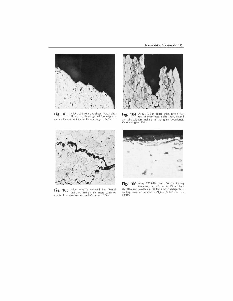
Fig. 103 Alloy 7075-T6 alclad sheet. Typical duc-tile fracture, showing the deformed grains
and necking at the fracture. Keller’s reagent. 200�
Fig. 104 Alloy 7075-T6 alclad sheet. Brittle frac-ture in overheated alclad sheet, caused
by solid-solution melting at the grain boundaries.Keller’s reagent. 200�
Fig. 105 Alloy 7075-T6 extruded bar. Typicalbranched intergranular stress corrosion
cracks. Transverse section. Keller’s reagent. 200�
Fig. 106 Alloy 7075-T6 sheet. Surface fretting(dark gray) on 3.2 mm (0.125 in.) thick
sheet that was fayed to a 4130 steel strap in a fatigue test.Fretting corrosion product is Al2O3. Keller’s reagent.1050�
Representative Micrographs / 151

(a) (b)
Fig. 107 Alloy 7075-T652 forging, showing the effect of saturation peening. (a) Longitudinal section. (b)Transverse section. The forging was peened with S230 cast steel shot to an Almen-gage intensity
of 0.006 to 0.008 A. The surface of the sheet (at top) shows deformation and roughening. Keller’s reagent. 150�
Fig. 108 Alloy 7075-T7352 forging, solution heattreated, cold reduced, and artificially aged.
Particles are insoluble (Fe,Mn)Al6 (dark gray). Some unre-solved Mg2Si may be present. This is a normal structure. Seealso Fig. 109. Keller’s reagent. 250�
Fig. 109 Alloy 7075-T7352 forging, solution heattreated, cold reduced, and artificially aged.
Eutectic melting temperature was exceeded during solutionheat treatment. Fusion voids (black areas) and agglomera-tion of insoluble phases (dark gray). Keller’s reagent. 250�
Fig. 110 Alloy 7178-T76 sheet, 3.2 mm (0.125 in.)thick, exposed in a test chamber containing a
fog of 5% NaCl for two weeks. Note exfoliation of the sheet.See also Fig. 111. Keller’s reagent. 75�
Fig. 111 Alloy 7178-T76 sheet, 3.1 mm (0.125 in.)thick, clad with 0.127 mm (0.005 in.) of alloy
7072 (3.2 mm, or 0.125 in., total thickness). Sacrificialcorrosion of cladding prevented exfoliation of sheet duringtesting. Keller’s reagent. 75�

Welded Wrought Aluminum Alloys
Fig. 112 Pressure weld (cold) in alloy 2014-T6 bar.The flow lines of the joint show the
movement of metal toward the edge of the bar duringweld upsetting. 0.5% HF. 150�
Fig. 113 Weld in alloy 2024-T4 sheet clad withalloy 1230. Core of alclad sheet used in
resistance spot weld shown in Fig. 114. The darkparticles are CuMgAl2, Cu2MnAl20, and Cu2FeAl7; lightparticles, CuAl2. See also Fig. 115–118. Keller’s reagent.500�
Fig. 114 Weld in alloy 2024-T4 sheet clad with alloy 1230. Resistance spotweld. Oval nugget has zone of columnar grains, surrounding
equiaxed grains. See also Fig. 115–118. Tucker’s reagent. 10�
Representative Micrographs / 153

Fig. 115 Weld in alloy 2024-T4 sheet clad with alloy 1230. Inner zone ofnugget of the resistance spot weld shown in Fig. 114. The structure
consists of small equiaxed grains. This inner zone is surrounded by an outer zonethat consists of columnar grains. See also Fig. 116. Keller’s reagent. 500�
Fig. 116 Weld in alloy 2024-T4 sheet clad with alloy1230. Outer zone of nugget of the weld
shown in Fig. 114. Columnar grains are normal to the edgeof the nugget. See also Fig. 115, which shows inner zone ofnugget. Keller’s reagent. 550�
Fig. 117 Weld in alloy 2024-T4 sheet clad withalloy 1230. Transition zone of the weld in
Fig. 114 showing eutectic segregation�depletion (lightband) at edge of nugget and concentration (dark band) inthe base metal. Keller’s reagent. 550�
Fig. 118 Weld in alloy 2024-T4 sheet clad withalloy 1230. Outer zone of nugget (at
interface) of resistance spot weld made in alclad sheets.Unfused cladding (right) projects into the weld nugget.See also Fig. 114. Keller’s reagent. 550�
Fig. 119 Parent metal alloy 2219-T37 sheet. Struc-ture of 3.2 mm (0.125 in.) thick sheet
used for the weld shown in Fig. 120 and 121. Longitu-dinal section. Elongated grains of solid solution withparticles of CuAl2 (light) and (Fe,Mn)3SiAl12 (dark)Keller’s reagent. 100�
154 / Introduction to Aluminum Alloys and Tempers

Fig. 120 Weld in alloy 2219-T37 sheet. Gas tungsten arc weld in a butt joint.Alloy ER 2319 filler metal. See also Fig. 122. Keller’s reagent. 10�
Fig. 121 Weld in alloy 2219-T37 sheet. Electron beam weld in a butt joint.Alloy ER 2319 filler metal. See also Fig. 123. Keller’s reagent. 10�
Representative Micrographs / 155

Fig. 122 Weld in alloy 2219-T37 sheet. Gas tungsten arc weld in a buttjoint. Alloy ER 2319 filler metal. Edge of the fusion zone of the gas
tungsten arc weld shown in Fig. 120. The base metal is on the left. See also Fig.123. Keller’s reagent. 100�
Fig. 123 Weld in alloy 2219-T37 sheet. Alloy ER 2319 filler metal. Edge ofthe fusion zone of the electron beam weld shown in Fig. 121. The
base metal is on the left. Keller’s reagent. 100�
156 / Introduction to Aluminum Alloys and Tempers
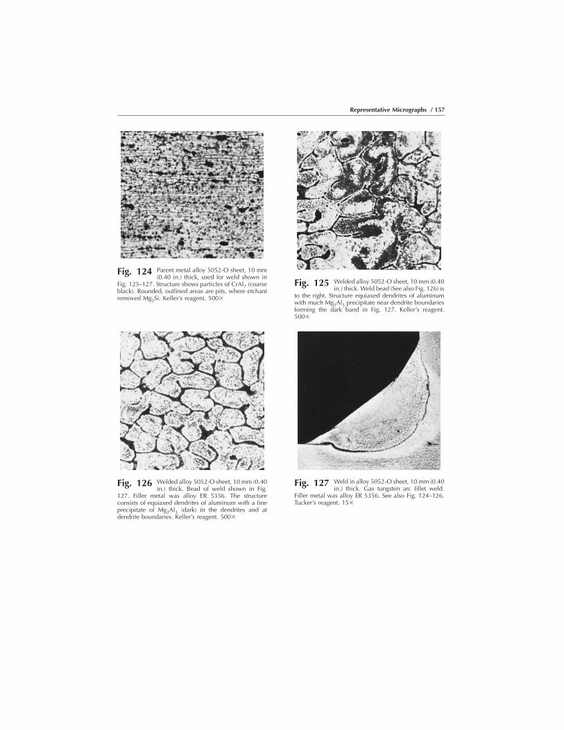
Fig. 124 Parent metal alloy 5052-O sheet, 10 mm(0.40 in.) thick, used for weld shown in
Fig. 125–127. Structure shows particles of CrAl7 (coarseblack). Rounded, outlined areas are pits, where etchantremoved Mg2Si. Keller’s reagent. 500�
Fig. 125 Welded alloy 5052-O sheet, 10 mm (0.40in.) thick. Weld bead (See also Fig. 126) is
to the right. Structure equiaxed dendrites of aluminumwith much Mg2Al3 precipitate near dendrite boundariesforming the dark band in Fig. 127. Keller’s reagent.500�
Fig. 126 Welded alloy 5052-O sheet, 10 mm (0.40in.) thick. Bead of weld shown in Fig.
127. Filler metal was alloy ER 5356. The structureconsists of equiaxed dendrites of aluminum with a fineprecipitate of Mg2Al3 (dark) in the dendrites and atdendrite boundaries. Keller’s reagent. 500�
Fig. 127 Weld in alloy 5052-O sheet, 10 mm (0.40in.) thick. Gas tungsten arc fillet weld.
Filler metal was alloy ER 5356. See also Fig. 124–126.Tucker’s reagent. 15�
Representative Micrographs / 157

Fig. 128 Weld in alloy 5456-H321 plate, 25 mm (1 in.) thick. Electron beam weld in a butt joint. No fillermetal was used. See Fig. 129 for details of the edge of the fusion zone. Keller’s reagent. 10�
Fig. 129 Weld in alloy 5456-H321 plate, 25 mm (1 in.) thick. Edge of fusionzone (base metal is at bottom) of the electron beam weld in Fig.
128. Keller’s reagent. 100�
Fig. 130 Weld in alloy 6061-T6 sheet, 1.6 mm (0.063 in.) thick. Gastungsten arc weld in a butt joint. Alternating current and ER 4043
filler metal were used. Note the extent of the heat-affected zone. See also Fig. 131and 138. Keller’s reagent. 5.5�
158 / Introduction to Aluminum Alloys and Tempers
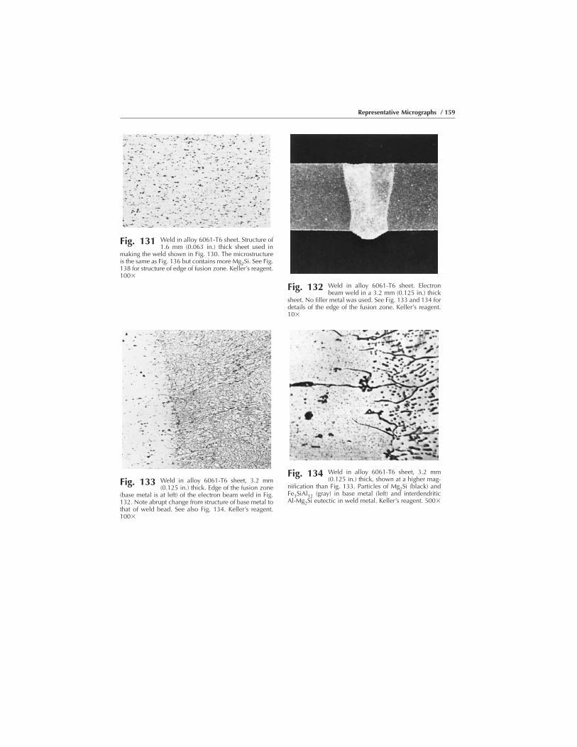
Fig. 131 Weld in alloy 6061-T6 sheet. Structure of1.6 mm (0.063 in.) thick sheet used in
making the weld shown in Fig. 130. The microstructureis the same as Fig. 136 but contains more Mg2Si. See Fig.138 for structure of edge of fusion zone. Keller’s reagent.100�
Fig. 132 Weld in alloy 6061-T6 sheet. Electronbeam weld in a 3.2 mm (0.125 in.) thick
sheet. No filler metal was used. See Fig. 133 and 134 fordetails of the edge of the fusion zone. Keller’s reagent.10�
Fig. 133 Weld in alloy 6061-T6 sheet, 3.2 mm(0.125 in.) thick. Edge of the fusion zone
(base metal is at left) of the electron beam weld in Fig.132. Note abrupt change from structure of base metal tothat of weld bead. See also Fig. 134. Keller’s reagent.100�
Fig. 134 Weld in alloy 6061-T6 sheet, 3.2 mm(0.125 in.) thick, shown at a higher mag-
nification than Fig. 133. Particles of Mg2Si (black) andFe3SiAl12 (gray) in base metal (left) and interdendriticAl-Mg2Si eutectic in weld metal. Keller’s reagent. 500�
Representative Micrographs / 159

Fig. 135 Weld in alloy 6061-T6 plate, 6.4 mm (0.250 in.) thick. Gastungsten arc weld in a butt joint. Alternating current and ER 4043
filler metal were used. See also Fig. 136 and 137 for other views of the weld.Keller’s reagent. 5.5�
Fig. 136 Weld in alloy 6061-T6 plate. Structure of6.4 mm (0.250 in.) thick plate used in
making the weld shown in Fig. 135. Elongated grains ofaluminum solid solution contain particles of Mg2Si(black). See also Fig. 131. Keller’s reagent 100�
Fig. 137 Welded alloy 6061-T6 plate. Edge offusion zone of a weld made in 6.4 mm
(0.250 in.) thick plate, using alternating current. Inter-dendritic network of aluminum-silicon eutectic (dark) inweld beam (right), dark band of Al-Mg2Si eutectic in theheat-affected zone. Keller’s reagent. 100�
Fig. 138 Welded alloy 6061-T6 plate. Edge offusion zone of a weld made in 1.6 mm
(0.063 in.) thick plate, using alternating current. Thebase metal is located on the left, and weld bead islocated on the right. The structure is the same as that inFig. 137, but some porosity (large, black areas) isevident. Keller’s reagent. 100�
Fig. 139 Welded alloy 6061-T6 plate. Edge offusion zone of a weld made in 6.4 mm
(0.250 in.) thick sheet, using straight-polarity directcurrent. Dark band of Al-Mg2Si eutectic in heat-affectedzone, next to weld beam (right), is narrower and morepronounced than in Fig. 137 (weld made with alternat-ing current). Keller’s reagent. 100�
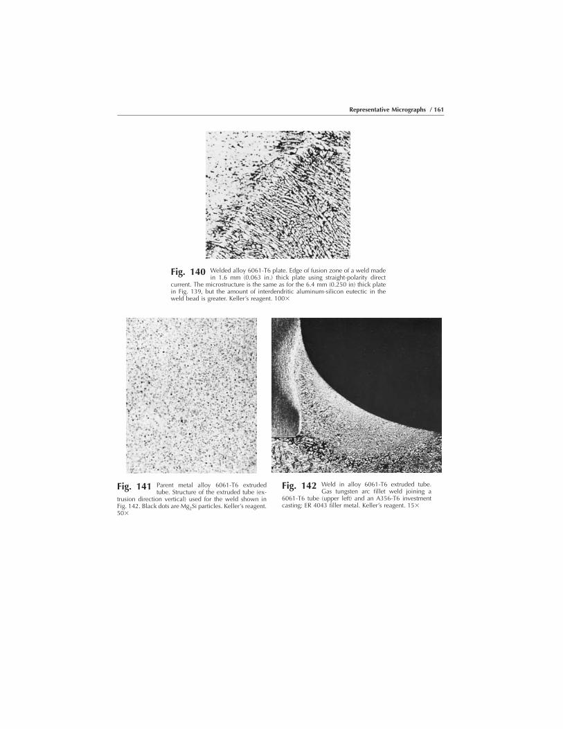
Fig. 140 Welded alloy 6061-T6 plate. Edge of fusion zone of a weld madein 1.6 mm (0.063 in.) thick plate using straight-polarity direct
current. The microstructure is the same as for the 6.4 mm (0.250 in) thick platein Fig. 139, but the amount of interdendritic aluminum-silicon eutectic in theweld bead is greater. Keller’s reagent. 100�
Fig. 141 Parent metal alloy 6061-T6 extrudedtube. Structure of the extruded tube (ex-
trusion direction vertical) used for the weld shown inFig. 142. Black dots are Mg2Si particles. Keller’s reagent.50�
Fig. 142 Weld in alloy 6061-T6 extruded tube.Gas tungsten arc fillet weld joining a
6061-T6 tube (upper left) and an A356-T6 investmentcasting; ER 4043 filler metal. Keller’s reagent. 15�
Representative Micrographs / 161
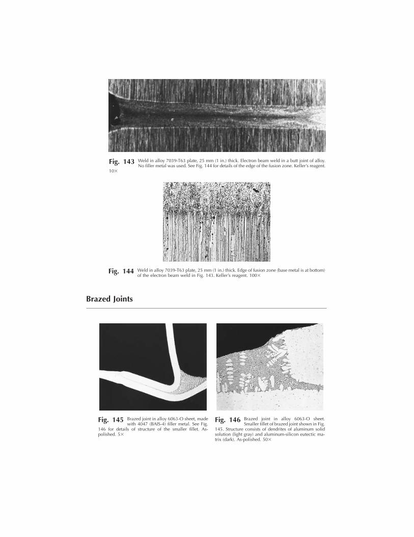
Brazed Joints
Fig. 143 Weld in alloy 7039-T63 plate, 25 mm (1 in.) thick. Electron beam weld in a butt joint of alloy.No filler metal was used. See Fig. 144 for details of the edge of the fusion zone. Keller’s reagent.
10�
Fig. 144 Weld in alloy 7039-T63 plate, 25 mm (1 in.) thick. Edge of fusion zone (base metal is at bottom)of the electron beam weld in Fig. 143. Keller’s reagent. 100�
Fig. 145 Brazed joint in alloy 6063-O sheet, madewith 4047 (BAIS-4) filler metal. See Fig.
146 for details of structure of the smaller fillet. As-polished. 5�
Fig. 146 Brazed joint in alloy 6063-O sheet.Smaller fillet of brazed joint shown in Fig.
145. Structure consists of dendrites of aluminum solidsolution (light gray) and aluminum-silicon eutectic ma-trix (dark). As-polished. 50�

Fig. 147 Brazed joint in alloy 7004-O sheet. Brazed joint between alloy7004-O sheets, made with alloy 4245 filler metal. See Fig. 148 for
details of the microstructure of the larger fillet. As-polished. 5�
Fig. 148 Brazed joint in alloy 7006-O sheet.Larger fillet of brazed joint shown in Fig.
147. Structure consists of dendrites of aluminum solidsolution (light), matrix of aluminum-silicon eutectic(mottled), and particles of primary silicon (dark). As-polished. 50�
Fig. 149 Brazed joint in alloy 3003 brazing sheets(clad on both sides with alloy 4343 filler
metal). Brazed joint in 12-O brazing sheets. Fillets showdendrites of solid solution (light) in aluminum-siliconeutectic matrix. 0.5% HF. 30�
Representative Micrographs / 163
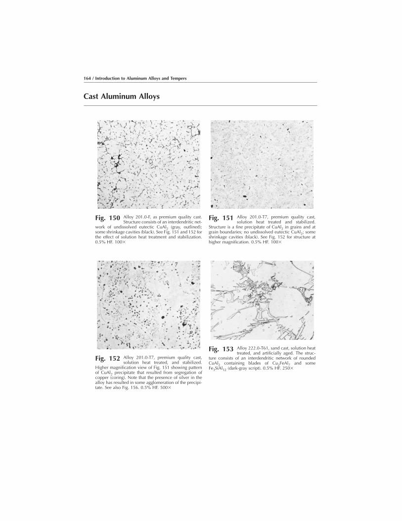
Cast Aluminum Alloys
Fig. 150 Alloy 201.0-F, as premium quality cast.Structure consists of an interdendritic net-
work of undissolved eutectic CuAl2 (gray, outlined);some shrinkage cavities (black). See Fig. 151 and 152 forthe effect of solution heat treatment and stabilization.0.5% HF. 100�
Fig. 151 Alloy 201.0-T7, premium quality cast,solution heat treated and stabilized.
Structure is a fine precipitate of CuAl2 in grains and atgrain boundaries; no undissolved eutectic CuAl2; someshrinkage cavities (black). See Fig. 152 for structure athigher magnification. 0.5% HF. 100�
Fig. 152 Alloy 201.0-T7, premium quality cast,solution heat treated, and stabilized.
Higher magnification view of Fig. 151 showing patternof CuAl2 precipitate that resulted from segregation ofcopper (coring). Note that the presence of silver in thealloy has resulted in some agglomeration of the precipi-tate. See also Fig. 156. 0.5% HF. 500�
Fig. 153 Alloy 222.0-T61, sand cast, solution heattreated, and artificially aged. The struc-
ture consists of an interdendritic network of roundedCuAl2 containing blades of Cu2FeAl7 and someFe3SiAl12 (dark-gray script). 0.5% HF. 250�
164 / Introduction to Aluminum Alloys and Tempers

Fig. 154 Alloy 224.0-F, as premium quality cast.The structure consists of an interdentritic
network of undissolved eutectic CuAl2 (gray, outlined).See Fig. 155 and 156 for the effect of heat treatment onthe structure. 0.5% HF. 100�
Fig. 155 Alloy 224.0-T7, as premium quality cast,solution heat treated, and stabilized.
Structure: fine CuAl2 precipitate; almost all of the eutec-tic CuAl2 present in Fig. 154 has been dissolved. Seealso higher magnification view in Fig. 156. 0.5% HF.100�
Fig. 156 Alloy 224.0-T7, premium quality cast,solution heat treated, and stabilized. En-
larged view of structure in Fig. 155 showing a fairly evenpattern of very fine particles of CuAl2 precipitates in thealuminum grains and slightly larger particles of theprecipitate at grain boundaries. 0.5% HF. 500�
Fig. 157 Alloy 238.0-F, as permanent mold cast.The structure consists of an interdendritic
network of rounded CuAl2 (light gray) containing bladesof Cu2FeAl7 (medium gray) and some particles of silicon(dark gray). 0.5% HF. 500�
Representative Micrographs / 165
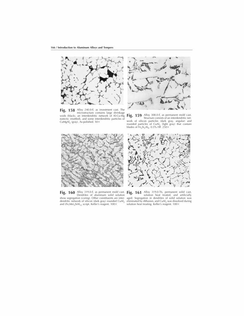
Fig. 158 Alloy 240.0-F, as investment cast. Themicrostructure contains large shrinkage
voids (black), an interdendritic network of Al-Cu-Mgeutectic (mottled), and some interdendritic particles ofCuMgAl2 (gray). As-polished. 50�
Fig. 159 Alloy 308.0-F, as permanent mold cast.Structure consists of an interdendritic net-
work of silicon particles (dark gray, angular) androunded particles of CuAl2 (light gray) that containblades of Fe2Si2Al9. 0.5% HF. 250�
Fig. 160 Alloy 319.0-F, as permanent mold cast.Dendrites of aluminum solid solution
show segregation (coring). Other constituents are inter-dendritic network of silicon (dark gray) rounded CuAl2and (Fe,Mn)3SiAl12 script. Keller’s reagent. 100�
Fig. 161 Alloy 319.0-T6, permanent solid cast,solution heat treated, and artificially
aged. Segregation in dendrites of solid solution waseliminated by diffusion, and CuAl2 was dissolved duringsolution heat treating. Keller’s reagent. 100�
166 / Introduction to Aluminum Alloys and Tempers

Fig. 162 Alloy 356.0-F as investment cast withsodium-modified ingot. Al2O3 inclusions.
Light-gray interdendritic network consists of particles ofsilicon. As-polished. 50�
Fig. 163 Alloy 356.0-T51, sand cast, artificiallyaged. The angular, dark-gray constituent
is silicon. Black script is Mg2Si. Blades are Fe2Si2Al9.Light script is FeMg3Si6Al8. 0.5% HF. 250�
Fig. 164 Alloy 356.0-T6. Hydrogen porosity(black) in a 356-T6 permanent mold cast-
ing that had been solution heat treated and artificiallyaged. 0.5% HF. 100�
Fig. 165 Alloy 356.0-T7, modified by sodium ad-dition, sand cast, solution heat treated,
and stabilized. Structure: rounded particles of siliconand blades of Fe2Si2Al9. 0.5% HF. 250�
Representative Micrographs / 167

Fig. 166 Alloy 356.0-F sand casting to which nograin refiner was added. The macrograin
size is 5 mm (0.20 in.). See also Fig. 167. Tucker’sreagent. 2�
Fig. 167 Alloy 356.0-F sand casting with 0.05% Tiand 0.005% B added as grain refiners.
Macrograin size is 1 mm (0.04 in.). Tucker’s reagent. 2�
(a) (b)
Fig. 168 Alloy A356.0-T6. Comparison of structure fineness using dendrite arm spacing (DAS). Two structures in theeutectic alloy A356.0-T6. (a) DAS � 20 μm. (b) DAS � 40 μm.
168 / Introduction to Aluminum Alloys and Tempers
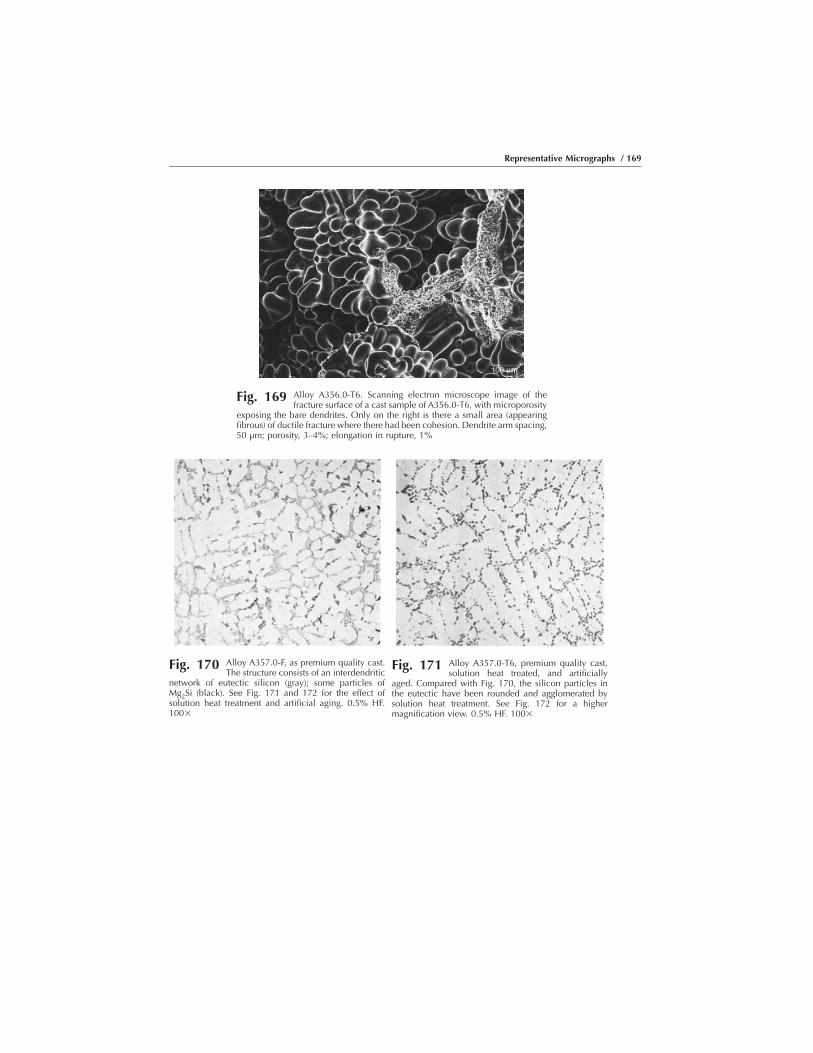
Fig. 169 Alloy A356.0-T6. Scanning electron microscope image of thefracture surface of a cast sample of A356.0-T6, with microporosity
exposing the bare dendrites. Only on the right is there a small area (appearingfibrous) of ductile fracture where there had been cohesion. Dendrite arm spacing,50 μm; porosity, 3–4%; elongation in rupture, 1%
Fig. 170 Alloy A357.0-F, as premium quality cast.The structure consists of an interdendritic
network of eutectic silicon (gray); some particles ofMg2Si (black). See Fig. 171 and 172 for the effect ofsolution heat treatment and artificial aging. 0.5% HF.100�
Fig. 171 Alloy A357.0-T6, premium quality cast,solution heat treated, and artificially
aged. Compared with Fig. 170, the silicon particles inthe eutectic have been rounded and agglomerated bysolution heat treatment. See Fig. 172 for a highermagnification view. 0.5% HF. 100�
Representative Micrographs / 169

Fig. 172 Alloy A357.0-T6, premium quality cast, solution heat treated, andartificially aged. At higher magnification than Fig. 171, showing
that very little undissolved Mg2Si (black particles) remained after solution heattreatment. No silicon precipitate is visible. See Fig. 174 for the effect ofinsufficient solution heat treatment. 0.5% HF. 500�
Fig. 173 Alloy A357.0-T61, permanent mold cast,solution heat treated at 540 °C (1000 °F)
for 12 h, quenched in water at 60 to 80 °C (140 to 180°F), aged at 155 °C (310 °F) for 10 h. A desirablestructure: rounded silicon particles and no undissolvedMg2Si. See also Fig. 176. 0.5% HF. 500�
Fig. 174 Alloy A357.0-T61, permanent mold cast,insufficiently solution heat treated and
artificially aged. Structure contains undissolved Mg2Si(black), and some of the particles of silicon are moreangular than those in the desirable structure shown inFig. 175. 0.5% HF. 500�
(a) (b)
Fig. 175 Alloy A357.0-T6. Commercial thixocast parts and the equiaxed development of the�-crystals in the solid solution before and after deformation (thixostructure). Here, the
shape and size of the primary crystals remain unchanged, the solidification process being limited to theresidual melt in the thin layers between them. (a) Microstructure of a log in A357.0-T6. (b) Microstructureof a landing gear component “thixoformed” in a die casting machine.
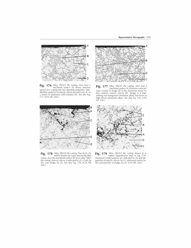
Fig. 176 Alloy 380.0-F die casting. Area near amachined surface (A) shows structure
typical of a casting that has desirable properties: inter-dendritic particles of eutectic silicon (B) and CuAl2 (C) ina matrix of aluminum solid solution (D). See also Fig.177. 0.5% HF. 260�
Fig. 177 Alloy 380.0-F die casting. Area near amachined surface (A) illustrates some pri-
mary crystals of sludge (B) in the aluminum matrix (C)that contains eutectic silicon (D). Sludge is a high-melting iron-manganese-chromium phase that forms inhigh-silicon aluminum alloys. See also Fig. 176. 0.5%HF. 130�
Fig. 178 Alloy 380.0-F die casting. Fine Al2O3 (A),which should not cause machining diffi-
culties, near the machined surface (B) of an alloy 380-Fdie casting. Eutectic silicon is indicated by (C); CuAl2 by(D); and sludge, by (E). See also Fig. 179. 0.5% HF.260�
Fig. 179 Alloy 380.0-F die casting shown at ahigher magnification than in Fig. 178.
Aluminum oxide particles are indicated by (A) and (B);particles of eutectic silicon, by (C); aluminum matrix, by(D); and particles of sludge, by (E). 0.5% HF. 520�
Representative Micrographs / 171
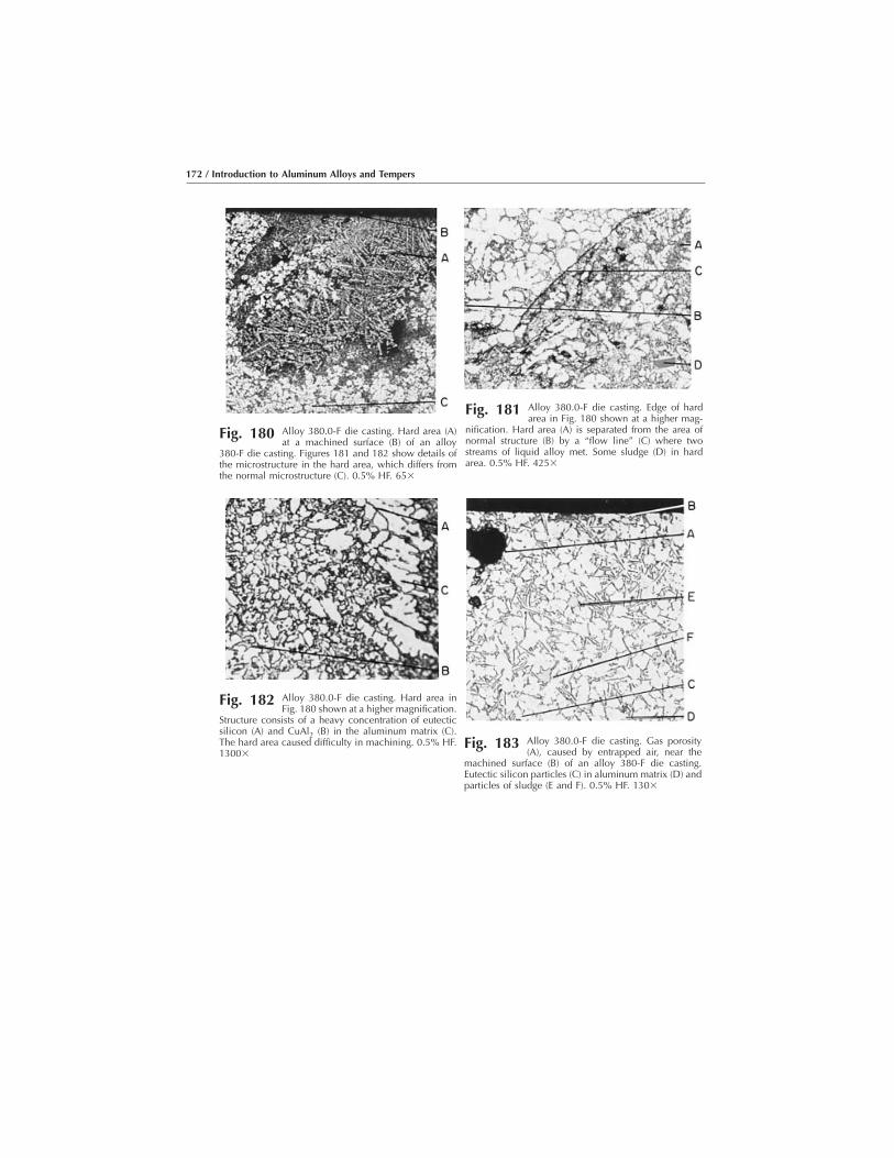
Fig. 180 Alloy 380.0-F die casting. Hard area (A)at a machined surface (B) of an alloy
380-F die casting. Figures 181 and 182 show details ofthe microstructure in the hard area, which differs fromthe normal microstructure (C). 0.5% HF. 65�
Fig. 181 Alloy 380.0-F die casting. Edge of hardarea in Fig. 180 shown at a higher mag-
nification. Hard area (A) is separated from the area ofnormal structure (B) by a “flow line” (C) where twostreams of liquid alloy met. Some sludge (D) in hardarea. 0.5% HF. 425�
Fig. 182 Alloy 380.0-F die casting. Hard area inFig. 180 shown at a higher magnification.
Structure consists of a heavy concentration of eutecticsilicon (A) and CuAl2 (B) in the aluminum matrix (C).The hard area caused difficulty in machining. 0.5% HF.1300�
Fig. 183 Alloy 380.0-F die casting. Gas porosity(A), caused by entrapped air, near the
machined surface (B) of an alloy 380-F die casting.Eutectic silicon particles (C) in aluminum matrix (D) andparticles of sludge (E and F). 0.5% HF. 130�
172 / Introduction to Aluminum Alloys and Tempers
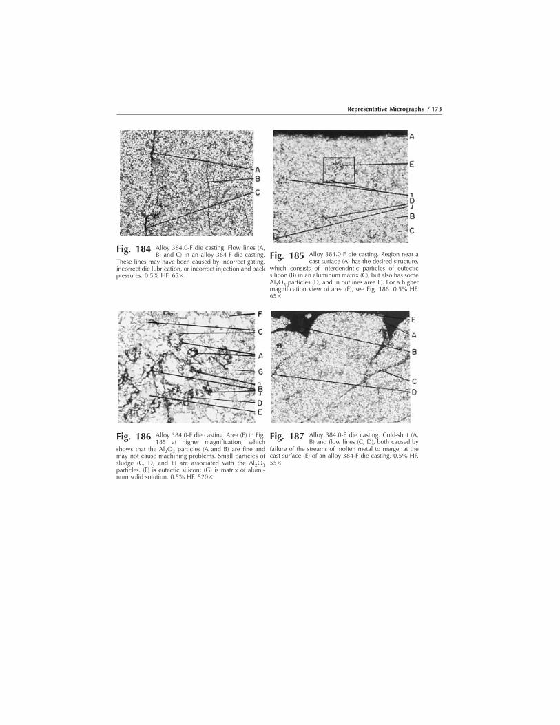
Fig. 184 Alloy 384.0-F die casting. Flow lines (A,B, and C) in an alloy 384-F die casting.
These lines may have been caused by incorrect gating,incorrect die lubrication, or incorrect injection and backpressures. 0.5% HF. 65�
Fig. 185 Alloy 384.0-F die casting. Region near acast surface (A) has the desired structure,
which consists of interdendritic particles of eutecticsilicon (B) in an aluminum matrix (C), but also has someAl2O3 particles (D, and in outlines area E). For a highermagnification view of area (E), see Fig. 186. 0.5% HF.65�
Fig. 186 Alloy 384.0-F die casting. Area (E) in Fig.185 at higher magnification, which
shows that the Al2O3 particles (A and B) are fine andmay not cause machining problems. Small particles ofsludge (C, D, and E) are associated with the Al2O3particles. (F) is eutectic silicon; (G) is matrix of alumi-num solid solution. 0.5% HF. 520�
Fig. 187 Alloy 384.0-F die casting. Cold-shut (A,B) and flow lines (C, D), both caused by
failure of the streams of molten metal to merge, at thecast surface (E) of an alloy 384-F die casting. 0.5% HF.55�
Representative Micrographs / 173

Fig. 188 Alloy 384.0-F die casting. Void (A), which was caused by poorfilling of the mold and associated flow lines (B) in an alloy 384-F
die casting. Figure 183 shows for flow lines without voids. 0.5% HF. 65�
Fig. 189 Alloy 384.0-F die casting. Gas-porositycavity (A), which was caused by en-
trapped air, at a machined surface (B) of an alloy 384-Fdie casting. Microstructure is eutectic silicon (C) in analuminum matrix (D); some sludge (E) is present. 0.5%HF. 130�
Fig. 190 Alloy 384.0-F. Coarse primary crystals ofsludge (A, B, C, and D) removed from
molten alloy 384 prior to die casting. The remainder ofthe structure consists of aluminum matrix (E), eutecticsilicon (F), and Al2O3 (G). 0.5% HF. 40�
174 / Introduction to Aluminum Alloys and Tempers
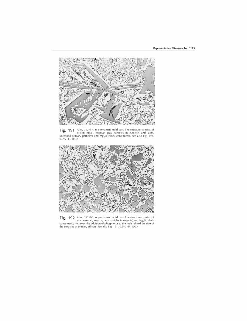
Fig. 191 Alloy 392.0-F, as permanent mold cast. The structure consists ofsilicon (small, angular, gray particles in eutectic, and large,
unrefined primary particles) and Mg2Si (black constituent). See also Fig. 192.0.5% HF. 100�
Fig. 192 Alloy 392.0-F, as permanent mold cast. The structure consists ofsilicon (small, angular, gray particles in eutectic) and Mg2Si (black
constituent); however, the addition of phosphorus to the melt refined the size ofthe particles of primary silicon. See also Fig. 191. 0.5% HF. 100�
Representative Micrographs / 175

Fig. 193 Alloy 413.0-F, as die cast. The structureconsists of eutectic silicon (gray constitu-
ent), blades of Fe2Si2Al9, and some light-gray particlesthat probably are Fe3SiAl12 in a matrix of aluminumsolid solution. Note extreme fineness of all particulateconstituents. 0.5% HF. 100�
Fig. 194 Alloy 413.0-F die casting. The gate area(A) of the casting has the desired struc-
ture, which consists of interdendritic particles of eutecticsilicon (B) and the light-etching matrix of aluminumsolid solution (C). 0.5% HF. 41�
Fig. 195 Alloy 413.0-F die casting. Gate area (A)of an alloy 413.0-F die casting, showing
gas porosity (B, C, and D) scattered from the outside wall(E) to the inside wall (F). See Fig. 196 for details of (G),a sound region. 0.5% HF. 11�
Fig. 196 Alloy 413.0-F die casting. Area (G) in Fig.195 at a higher magnification. Angular
eutectic silicon (A) in matrix of aluminum solid solution(B) in normal and rounded silicon in undesirable struc-tures (C and D). 0.5% HF. 520�
176 / Introduction to Aluminum Alloys and Tempers

Fig. 197 Alloy 413.0-F die casting. Gate area (A).There are areas of undesirable silicon
structure (B) and a gas pore (C), which was caused by airentrapment, in a region that otherwise exhibits a normalstructure (D). 0.5% HF. 41�
Fig. 198 Alloy 413.0-F die casting. Gate area (A)of a die casting that has a cold-shut void
(B) and a region of undesirable structure (C and D)surrounded by areas of normal structure (E and F). Seealso Fig. 199 and 200. 0.5% HF. 11�
Fig. 199 Alloy 413.0-F die casting. Area of cold-shut void (A) in Fig. 198. The void re-
sulted when two streams of molten metal failed to mergeand interdiffuse. One of the streams produced a normalstructure (B), and the other produced an undesirablestructure (C). See also Fig. 200 and 201. 0.5% HF. 35�
Fig. 200 Alloy 413.0-F die casting. Inner end ofcold-shut void (A) in Fig. 199 showing
start of flow line between region of normal structure (B),with eutectic silicon (C) of normal shape in matrix ofaluminum solid solution (D), and region of undesirablestructure (E). See also Fig. 201. 0.5% HF. 520�
Representative Micrographs / 177

Fig. 201 Alloy 413.0-F die casting. Continuation of flow line (A) in Fig. 200,separating normal structure (B), with angular silicon (C) in alumi-
num matrix (D), from undesirable structure (E), with rounded silicon (F) inaluminum matrix (G). Line extends across entire section thickness. 0.5% HF.520�
(a) (b) (c)
Fig. 202 Alloy B413.0-F. (a) Angular. (b) Lamellar. (c) Modified
178 / Introduction to Aluminum Alloys and Tempers
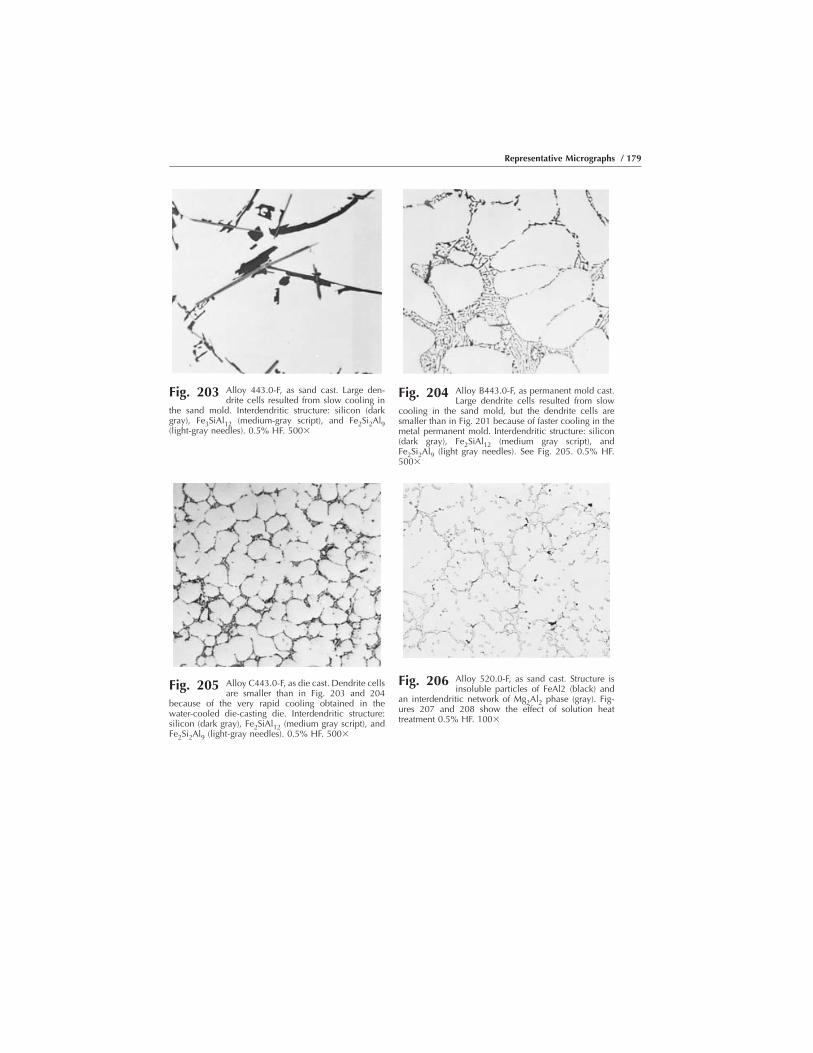
Fig. 203 Alloy 443.0-F, as sand cast. Large den-drite cells resulted from slow cooling in
the sand mold. Interdendritic structure: silicon (darkgray), Fe3SiAl12 (medium-gray script), and Fe2Si2Al9(light-gray needles). 0.5% HF. 500�
Fig. 204 Alloy B443.0-F, as permanent mold cast.Large dendrite cells resulted from slow
cooling in the sand mold, but the dendrite cells aresmaller than in Fig. 201 because of faster cooling in themetal permanent mold. Interdendritic structure: silicon(dark gray), Fe2SiAl12 (medium gray script), andFe2Si2Al9 (light gray needles). See Fig. 205. 0.5% HF.500�
Fig. 205 Alloy C443.0-F, as die cast. Dendrite cellsare smaller than in Fig. 203 and 204
because of the very rapid cooling obtained in thewater-cooled die-casting die. Interdendritic structure:silicon (dark gray), Fe2SiAl12 (medium gray script), andFe2Si2Al9 (light-gray needles). 0.5% HF. 500�
Fig. 206 Alloy 520.0-F, as sand cast. Structure isinsoluble particles of FeAl2 (black) and
an interdendritic network of Mg2Al2 phase (gray). Fig-ures 207 and 208 show the effect of solution heattreatment 0.5% HF. 100�
Representative Micrographs / 179

Fig. 207 Alloy 520.0-T4, sand cast, solution heattreated at 425 °C (800 °F). Structure is in-
soluble particles of FeAl2 (black) and an interdendriticnetwork of Mg2Al2 phase (gray), although the solution heattreating has dissolved most of the Mg2Al2 phase. See alsoFig. 208. 0.5% HF. 100�
Fig. 208 Alloy 520.0-T4, sand cast, solution heattreated. Solidus was exceeded during solu-
tion heat treating, and melting of the eutectic has formed alacy network and rosettes of Mg2Al2 phase (gray). See alsoFig. 207. 0.5% HF. 500�
Fig. 209 Alloy D712.0-F, as sand cast. Interdendritic network: particles ofCrAl7, Fe3SiAl12, and FeAl6. Note the segregation (coring) of
magnesium and zinc in the grains. See also Fig. 210. Keller’s reagent. 100�
Fig. 210 Alloy D712.0-F, as investment cast. Interden-dritic network: particles of CrAl7, Fe2SiAl12,
and FeAl6. Intergranular fusion voids (black) were caused byeutectic melting as a result of exceeding the solidus tem-perature during dip brazing. Keller’s reagent. 100�
Fig. 211 Alloy 850.0-F, as permanent mold cast. Notehot tear, which occurred at or above the
solidus, and some Al-CuAl2 eutectic (gray) back filling oftear. Particles of tin (rounded), NiAl3, and FeNiAl9 (bothirregular). 0.5% HF. 100�

Welded Cast Aluminum Alloys
Fig. 212 Welded alloy 295.0-T6, investment casting. Electronbeam weld in an alloy 295.0-T6 investment casting.
Weld was made without filler metal. Overheating during weldingresulted in a considerable amount of dropthrough (right), withaccompanying longitudinal shrinkage cracks in the center of theweld metal. See also Fig. 213. Tucker’s reagent. 5�
Fig. 213 Welded alloy 295.0-T6, in-vestment casting. Edge of fu-
sion zone of weld shown in Fig. 212 (basemetal at bottom). Large dendrites of solidsolution in base metal, small dendrites inweld bead. Al-CuAl2-Si eutectic in both.Keller’s reagent. 150�
Fig. 214 Welded alloy 356.0-F, investment cast-ing. Edge of a fusion zone of a gas
tungsten arc repair weld in a 356.0-F investment casting.Alternating current and R-SG70A filler metal were used.Interdendritic aluminum-silicon eutectic (gray); porosity(black). See also Fig. 215. Keller’s reagent. 50�
Fig. 215 Welded alloy 356.0-F, investment castingafter solution heat treatment. Particles of
eutectic silicon have become rounded and agglomer-ated. Zone between weld bead and heat-affected zone isless clearly defined than in Fig. 214; porosity remains.Keller’s reagent. 50�
Representative Micrographs / 181

Welded Wrought-to-Cast Alloys
Fig. 216 Welded alloy 6061-T6 to A356.0-T6. Gas tungsten arc fillet weldjoining a 6061-T6 tube (upper left) with an A356.0-T6 investment
casting. ER 4043 filler metal. Keller’s reagent. 15�
Fig. 217 Welded alloy 6061-T6 toA356.0-T6. Structure of
A356.0-T6 investment casting (sodium-modi-fied, grain-refined) used for the weld shown inFig. 216. Interdendritic network is eutectic sili-con. Keller’s reagent. 50�
Fig. 218 Welded alloy 6061-T6 to A356.0-T6.Edge of the fusion zone of the weld
shown in Fig. 216, with the tube at the left and the weldbead at the right. Aluminum-silicon eutectic is presentbetween the dendrites of the weld bead; Al-Mg2Sieutectic is between the grains of the heat-affected zoneof the tube. Keller’s reagent. 50�
182 / Introduction to Aluminum Alloys and Tempers
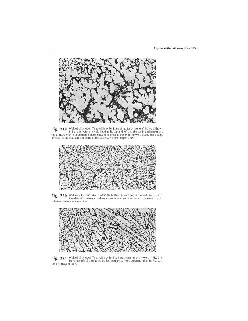
Fig. 219 Welded alloy 6061-T6 to A356.0-T6. Edge of the fusion zone of the weld shownin Fig. 216, with the weld bead at the top and left and the casting at bottom and
right. Interdendritic aluminum-silicon eutectic is present, some in the weld bead, and a largeamount in the heat-affected zone of the casting. Keller’s reagent. 50�
Fig. 220 Welded alloy 6061-T6 to A356.0-T6. Bead (near tube) at the weld in Fig. 216.Interdendritic network of aluminum-silicon eutectic is present in the matrix solid
solution. Keller’s reagent. 50�
Fig. 221 Welded alloy 6061-T6 to A356.0-T6. Bead (near casting) of the weld in Fig. 216.Dendrites of solid solution are less equiaxed, more columnar than in Fig. 220.
Keller’s reagent. 50�
Representative Micrographs / 183

Welded Aluminum to Steel
Welded Aluminum to Copper
Fig. 222 Aluminum-steel weld. Explosive weldedjoint between aluminum sheet (top) and
steel showing characteristic ripples at the interface. Aripple is shown at a high magnification in Fig. 223.As-polished. 6�
Fig. 223 Aluminum-steel weld. Ripple at interfaceof explosive welded joint between alumi-
num sheet (top) and steel. Cracks have appeared in thedark-gray phase (which probably is FeAl3). As-polished.60�
Fig. 224 Aluminum-copper weld. Explosive welded joint between alumi-num sheet (top) and copper. Cracks (black) have appeared in the
aluminum-copper phase (light gray) at the relatively smooth interface. As-polished. 225�
184 / Introduction to Aluminum Alloys and Tempers
APPENDIX
Terminology
The following list of terms covers wrought and cast aluminum productsand their production. These terms may be helpful in understanding andinterpreting other information in this book regarding aluminum alloys,tempers, production processes, and applications.
Most of these terms come from the Aluminum Association publicationAluminum Standards and Data and are republished with the permission ofthe Aluminum Association. The terms included for casting processes aretaken from publications of the American Foundrymen’s Society (AFS);the reader is referred to those publications for more complete terminologyfor casting and casting processes.
The list is not intended to include every term likely to be used withinthe aluminum industry, but it is hoped that most of the terms that areunique to the industry are defined and may help in understanding the alloyand temper designations that are the subject of this book.
Note: Italicized words within a definition can be found as a separateentry in this list.
A
AFS. American Foundrymen’s SocietyAMS. Aerospace Material Specification.ANSI. American National Standards Institute.ASME. American Society of Mechanical Engineers.AWS. American Welding Society.abrasion. See mark, traffıc.age hardening. An aging process that results in increased strength and
hardness.age softening. Spontaneous decrease of strength and hardness that takes
place at room temperature in certain strain-hardened alloys containingmagnesium.
Introduction to Aluminum Alloys and TempersJ. Gilbert Kaufman, p187-224 DOI:10.1361/iaat2000p187
Copyright © 2000 ASM International® All rights reserved. www.asminternational.org
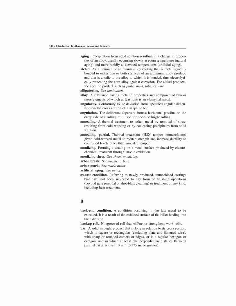
aging. Precipitation from solid solution resulting in a change in proper-ties of an alloy, usually occurring slowly at room temperature (naturalaging) and more rapidly at elevated temperatures (artificial aging).
alclad. An aluminum or aluminum-alloy coating that is metallurgicallybonded to either one or both surfaces of an aluminum alloy product,and that is anodic to the alloy to which it is bonded, thus electrolyti-cally protecting the core alloy against corrosion. For alclad products,see specific product such as plate, sheet, tube, or wire.
alligatoring. See lamination.alloy. A substance having metallic properties and composed of two or
more elements of which at least one is an elemental metal.angularity. Conformity to, or deviation from, specified angular dimen-
sions in the cross section of a shape or bar.angulation. The deliberate departure from a horizontal passline on the
entry side of a rolling mill used for one-side bright rolling.annealing. A thermal treatment to soften metal by removal of stress
resulting from cold working or by coalescing precipitates from solidsolution.
annealing, partial. Thermal treatment (H2X temper nomenclature)given cold-worked metal to reduce strength and increase ductility tocontrolled levels other than annealed temper.
anodizing. Forming a coating on a metal surface produced by electro-chemical treatment through anodic oxidation.
anodizing sheet. See sheet, anodizing.arbor break. See buckle, arbor.arbor mark. See mark, arbor.artificial aging. See aging.as-cast condition. Referring to newly produced, unmachined castings
that have not been subjected to any form of finishing operations(beyond gate removal or shot-blast cleaning) or treatment of any kind,including heat treatment.
B
back-end condition. A condition occurring in the last metal to beextruded. It is a result of the oxidized surface of the billet feeding intothe extrusion.
backup roll. Nongrooved roll that stiffens or strengthens work rolls.bar. A solid wrought product that is long in relation to its cross section,
which is square or rectangular (excluding plate and flattened wire),with sharp or rounded comers or edges, or is a regular hexagon oroctagon, and in which at least one perpendicular distance betweenparallel faces is over 10 mm (0.375 in. or greater).
188 / Introduction to Aluminum Alloys and Tempers
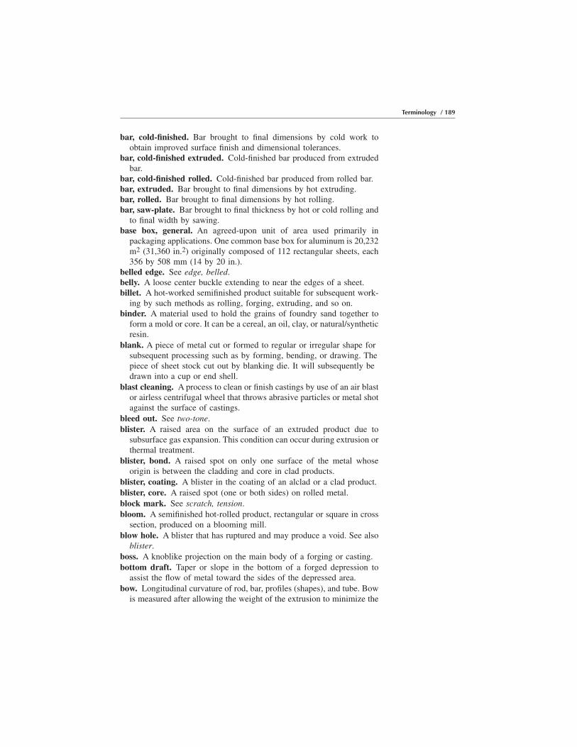
bar, cold-finished. Bar brought to final dimensions by cold work toobtain improved surface finish and dimensional tolerances.
bar, cold-finished extruded. Cold-finished bar produced from extrudedbar.
bar, cold-finished rolled. Cold-finished bar produced from rolled bar.bar, extruded. Bar brought to final dimensions by hot extruding.bar, rolled. Bar brought to final dimensions by hot rolling.bar, saw-plate. Bar brought to final thickness by hot or cold rolling and
to final width by sawing.base box, general. An agreed-upon unit of area used primarily in
packaging applications. One common base box for aluminum is 20,232m2 (31,360 in.2) originally composed of 112 rectangular sheets, each356 by 508 mm (14 by 20 in.).
belled edge. See edge, belled.belly. A loose center buckle extending to near the edges of a sheet.billet. A hot-worked semifinished product suitable for subsequent work-
ing by such methods as rolling, forging, extruding, and so on.binder. A material used to hold the grains of foundry sand together to
form a mold or core. It can be a cereal, an oil, clay, or natural/syntheticresin.
blank. A piece of metal cut or formed to regular or irregular shape forsubsequent processing such as by forming, bending, or drawing. Thepiece of sheet stock cut out by blanking die. It will subsequently bedrawn into a cup or end shell.
blast cleaning. A process to clean or finish castings by use of an air blastor airless centrifugal wheel that throws abrasive particles or metal shotagainst the surface of castings.
bleed out. See two-tone.blister. A raised area on the surface of an extruded product due to
subsurface gas expansion. This condition can occur during extrusion orthermal treatment.
blister, bond. A raised spot on only one surface of the metal whoseorigin is between the cladding and core in clad products.
blister, coating. A blister in the coating of an alclad or a clad product.blister, core. A raised spot (one or both sides) on rolled metal.block mark. See scratch, tension.bloom. A semifinished hot-rolled product, rectangular or square in cross
section, produced on a blooming mill.blow hole. A blister that has ruptured and may produce a void. See also
blister.boss. A knoblike projection on the main body of a forging or casting.bottom draft. Taper or slope in the bottom of a forged depression to
assist the flow of metal toward the sides of the depressed area.bow. Longitudinal curvature of rod, bar, profiles (shapes), and tube. Bow
is measured after allowing the weight of the extrusion to minimize the
Terminology / 189

deviation. Bow can be caused by a nonuniform extrusion rate acrossthe cross section, resulting in one portion of the extrusion being longerthan the other or nonuniform contraction during quenching.
bow, lateral. Deviation from straight of a longitudinal edge.bow, longitudinal. Curvature in the plane of sheet or plate in the rolling
direction.bow, transverse. Curvature across the rolling direction of sheet or plate.brazing. Joining metals by fusion of nonferrous alloys that have melting
points above 425 °C (800 °F) but lower than those of the metals beingjoined. This may be accomplished by means of a torch (torch brazing),in a furnace (furnace brazing), or by dipping in a molten flux bath (dipor flux brazing).
brazing rod. A rolled, extruded, or cast round filler metal for use injoining by brazing.
brazing sheet. Sheet of a brazing alloy or sheet clad with a brazing alloyon one or both sides.
brazing wire. Wire for use as a filler metal in joining by brazing.bright sheet. See sheet, (1SBMF), (S1SBF) and (S2SBF).bristle mark. See mark, bristle.broken edge. See edge, broken.broken eie. A deviation from the desired cross section due to the absence
of a certain portion of the die used to extrude the profile (shape).broken matte finish. Nonuniform surface on the inside of packed rolled
foil (bright spots).broken surface. See crazing.bruise. See mark, roll bruise.buckle. A distortion of the surface of the metal.buckle, arbor. Bend, crease, wrinkle, or departure from flat, occurring
perpendicular to the slit edge of a coil and which are repetitive innature, with severity decreasing as the distance increases in the coilfrom the original source. Normally, it is found on the inside diameterof a coil but can appear on the coil outside diameter as a result of aprior winding operation.
buckle, center. Undulation (wavy region) in the center of the metal.buckle, edge. Undulation (wavy region) along the edge(s) of the metal.buckle, oil can. See buckle, trapped.buckle, quarter. Undulation (wavy region) that occurs approximately at
both quarter points across the width.buckle, trapped. Undulation (wavy region) that is smaller sized and
often circular in shape.buffing. A mechanical finishing operation in which fine abrasives are
applied to a metal surface by rotating fabric wheels for the purpose ofdeveloping a lustrous finish.
buff streak. See streak.burnish streak. See streak, burnish.
190 / Introduction to Aluminum Alloys and Tempers

burnishing. See two-tone.burr. A thin ridge of roughness left by a cutting operation such as
slitting, trimming, shearing, blanking, or sawing.bursting strength. The pressure required to rupture a foil specimen
when it is tested in a mullen instrument under specified conditions. Seealso mullen test.
bus bar. A rigid electric conductor in the form of a bar.butt-seam tube. See tube, open-seam.
C
Camber. See bow, lateral.carbon mark. See mark, carbon.casting (noun). An object formed by pouring, pumping, or sucking
molten metal into a mold or set of dies and allowing it to solidify.casting (verb). The act of pouring, pumping, or sucking molten metal
into a mold (made of sand, metal, ceramic, or graphite) or a set of metaldies.
casting strains. Strains in a cast metal component resulting from internalstresses created during cooling. Heat treatment and other processes areused to remove these strains.
casting yield. The weight of casting or castings divided by the totalweight of metal poured into the mold, expressed as a percent.
center. The difference in thickness between the middle and edges(average) of a sheet.
centrifugal casting. In the centrifugal casting process, commonly ap-plied to cylindrical castings, a permanent mold is rotated rapidly aboutthe axis of the casting while a measured amount of molten metal ispoured into the mold cavity. Centrifugal force is used to hold the metalagainst the outer walls of the mold with the volume of metal poureddetermining the wall thickness of the casting.
center buckle. See buckle.chafing. See mark, traffıc.chatter mark. See mark, chatter.chill. Metal insert placed in a mold to increase speed of cooling. Internal
chills are placed in the mold cavity and become integral parts of thecasting.
chip mark. See dent, repeating.chop. Metal sheared from a vertical surface of a die forging, which is
spread by the die over an adjoining horizontal surface.chucking lug. A lug or boss added to a forging so that on-center
machining and forming may be performed with one setup or checking.This lug is finally machined or cut away.
cinching. See scratch, tension.
Terminology / 191

circle. A circular blank fabricated from plate, sheet, or foil.clad sheet. See sheet, clad.cleaning. Removal of sand and excess metal from a sand casting,
ceramic and excess metal from an investment casting, or excess metalfrom a die casting.
CO2 process. Molds and cores, made with sand containing sodiumsilicate, which are hardened by permeating the sand with carbondioxide gas.
coating. Continuous film on the surface of a product.coating blister. See blister, coating.coating buildup. A coating thickness greater than nominal in localized
area of sheet, usually along edges, due to uneven application tech-niques.
coating, conversion. An inorganic pretreatment sometimes applied to ametal surface to enhance coating adhesion and to retard corrosion.
coating drip. A nonuniform extraneous deposit of coating on the coatedsheet.
coating, high or low. Failure of the coating to meet the agreed-uponthickness limits measured in weight per unit area.
coating oven trash. See dirt.coating streak. See streak, coating.cobble. A jamming of the mill by aluminum product while being rolled;
a piece of aluminum, which for any reason has become so bent ortwisted that it must be withdrawn from the rolling operation andscrapped.
coil curvature. See coil set.coil orientation, clockwise coil. With the coil core vertical (eye to the
sky) and viewed from above, a trace of the metal edge from the insidediameter to the outside diameter involves clockwise movement.
coil orientation, counterclockwise (anticlockwise) coil. With the coilcore vertical (eye to the sky) and viewed from above, a trace of themetal edge from the inside diameter to the outside diameter involvescounterclockwise (anticlockwise) movement.
coil set. Longitudinal bow in an unwound coil in the same direction ascurvature of the wound coil.
coil set differential. The difference in coil set from edge to edge of acoiled sheet sample. It is measured with the sample on a flat table,concave side up, and is the difference in elevation of the comers on oneend.
coil set, reversed. Longitudinal bow in an unwound coil in the directionopposite the curvature of the wound coil.
coiled sheet. See sheet, coiled.cold shut. (1) A linear discontinuity in a cast surface caused when
meeting streams of metal fail to merge prior to solidification. (2)
192 / Introduction to Aluminum Alloys and Tempers

Forging defect developed by metal flowing into a section from twodirections, resulting in a discontinuity at the junction.
cold working. Plastic (i.e., permanent) deformation of metal at suchtemperature and rate that strain hardening occurs.
collapse. Out-of-round condition of coil often due to inappropriatetension during rewinding operations.
coloring. A finishing process, or combination of processes, that alters theappearance of an aluminum surface via coating, chemical, and/ormechanical operations.
combination die (multiple-cavity die). In die casting practice, a diewith two or more different cavities for different castings.
concavity. Curved as the inner surface of a sphere. See also convexity.concentricity. Conformance to a common center as, for example, the
inner and outer walls of round tube.condensation stain. See corrosion, water stain.condenser tube. The term “heat-exchanger tube” is preferred, unless
specific reference to a condenser application is intended.conduit. A tube used to protect electric wiring. See also tubing, electrical
metallic.conduit, rigid. Conduit having dimensions of ANSI schedule 40 pipe in
standardized length with threaded ends.coned-out coil. See telescoping.contour. That portion of the outline of a transverse cross section of an
extruded shape that is represented by a curved line or curved lines.controlled cooling. Process by which a metal object is cooled from an
elevated temperature in a manner that avoids hardening, cracking, orinternal damage.
conversion coating, can ends. See coating, conversion.convexity. Curved such as the outer surface of a sphere. See also
concavity.core (for casting). Separable part of a mold that usually is made of sand
and a binder to create openings and various specially shaped cavities incastings.
core (for rolled products). A hollow cylinder on which a coiled productmay be wound that forms the inside diameter of a coil.
core blister. See blister, core.coring. See back-end condition.corner turnup. A distortion, buckle, or twist condition that causes the
corner(s) of the sheet to deviate from a perfectly flat plane on whichit rests.
corrosion. The deterioration of a metal by chemical or electrochemicalreaction with its environment.
corrosion, exfoliation. Corrosion that progresses approximately parallelto the metal surface, causing layers of the metal to be elevated by theformation of corrosion product.
Terminology / 193
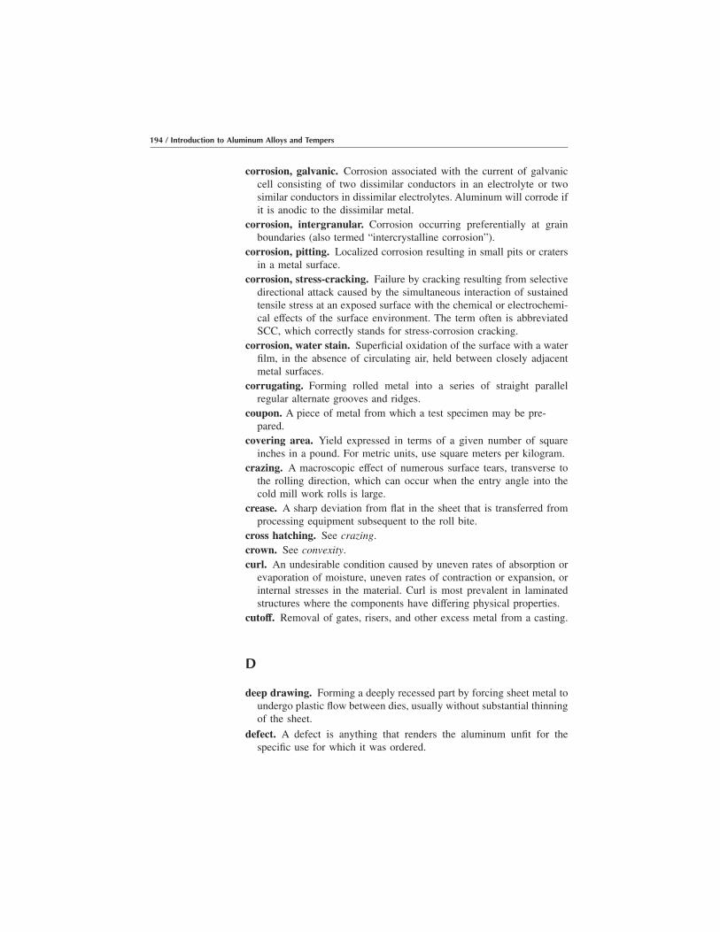
corrosion, galvanic. Corrosion associated with the current of galvaniccell consisting of two dissimilar conductors in an electrolyte or twosimilar conductors in dissimilar electrolytes. Aluminum will corrode ifit is anodic to the dissimilar metal.
corrosion, intergranular. Corrosion occurring preferentially at grainboundaries (also termed “intercrystalline corrosion”).
corrosion, pitting. Localized corrosion resulting in small pits or cratersin a metal surface.
corrosion, stress-cracking. Failure by cracking resulting from selectivedirectional attack caused by the simultaneous interaction of sustainedtensile stress at an exposed surface with the chemical or electrochemi-cal effects of the surface environment. The term often is abbreviatedSCC, which correctly stands for stress-corrosion cracking.
corrosion, water stain. Superficial oxidation of the surface with a waterfilm, in the absence of circulating air, held between closely adjacentmetal surfaces.
corrugating. Forming rolled metal into a series of straight parallelregular alternate grooves and ridges.
coupon. A piece of metal from which a test specimen may be pre-pared.
covering area. Yield expressed in terms of a given number of squareinches in a pound. For metric units, use square meters per kilogram.
crazing. A macroscopic effect of numerous surface tears, transverse tothe rolling direction, which can occur when the entry angle into thecold mill work rolls is large.
crease. A sharp deviation from flat in the sheet that is transferred fromprocessing equipment subsequent to the roll bite.
cross hatching. See crazing.crown. See convexity.curl. An undesirable condition caused by uneven rates of absorption or
evaporation of moisture, uneven rates of contraction or expansion, orinternal stresses in the material. Curl is most prevalent in laminatedstructures where the components have differing physical properties.
cutoff. Removal of gates, risers, and other excess metal from a casting.
D
deep drawing. Forming a deeply recessed part by forcing sheet metal toundergo plastic flow between dies, usually without substantial thinningof the sheet.
defect. A defect is anything that renders the aluminum unfit for thespecific use for which it was ordered.
194 / Introduction to Aluminum Alloys and Tempers
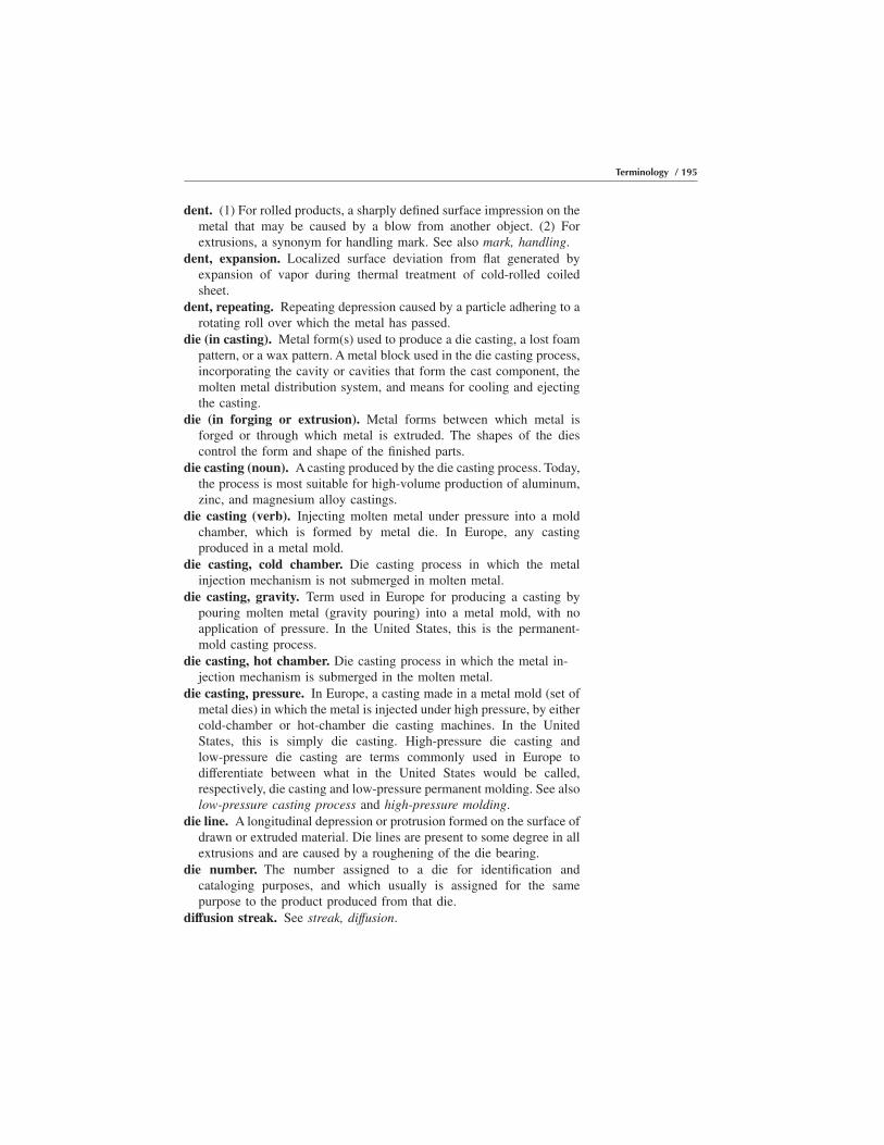
dent. (1) For rolled products, a sharply defined surface impression on themetal that may be caused by a blow from another object. (2) Forextrusions, a synonym for handling mark. See also mark, handling.
dent, expansion. Localized surface deviation from flat generated byexpansion of vapor during thermal treatment of cold-rolled coiledsheet.
dent, repeating. Repeating depression caused by a particle adhering to arotating roll over which the metal has passed.
die (in casting). Metal form(s) used to produce a die casting, a lost foampattern, or a wax pattern. A metal block used in the die casting process,incorporating the cavity or cavities that form the cast component, themolten metal distribution system, and means for cooling and ejectingthe casting.
die (in forging or extrusion). Metal forms between which metal isforged or through which metal is extruded. The shapes of the diescontrol the form and shape of the finished parts.
die casting (noun). A casting produced by the die casting process. Today,the process is most suitable for high-volume production of aluminum,zinc, and magnesium alloy castings.
die casting (verb). Injecting molten metal under pressure into a moldchamber, which is formed by metal die. In Europe, any castingproduced in a metal mold.
die casting, cold chamber. Die casting process in which the metalinjection mechanism is not submerged in molten metal.
die casting, gravity. Term used in Europe for producing a casting bypouring molten metal (gravity pouring) into a metal mold, with noapplication of pressure. In the United States, this is the permanent-mold casting process.
die casting, hot chamber. Die casting process in which the metal in-jection mechanism is submerged in the molten metal.
die casting, pressure. In Europe, a casting made in a metal mold (set ofmetal dies) in which the metal is injected under high pressure, by eithercold-chamber or hot-chamber die casting machines. In the UnitedStates, this is simply die casting. High-pressure die casting andlow-pressure die casting are terms commonly used in Europe todifferentiate between what in the United States would be called,respectively, die casting and low-pressure permanent molding. See alsolow-pressure casting process and high-pressure molding.
die line. A longitudinal depression or protrusion formed on the surface ofdrawn or extruded material. Die lines are present to some degree in allextrusions and are caused by a roughening of the die bearing.
die number. The number assigned to a die for identification andcataloging purposes, and which usually is assigned for the samepurpose to the product produced from that die.
diffusion streak. See streak, diffusion.
Terminology / 195
dimensional stability. Ability of a casting to remain unchanged in sizeand shape under ordinary atmospheric conditions.
dirt. Foreign debris from rolling or post-rolling operations imbedded inor under the coating.
disc. A circular blank fabricated from plate, sheet, or foil, from which acentral concentric area has been removed.
double shear notch. See notch, double shear.draft. Taper on the sides of a die or mold impression to facilitate removal
of forgings, castings, or patterns from dies or molds.drag mark. See rub, tool.draw and iron-can bodies. Term that refers to a method of fabricating
a can body in which a cup is drawn from flat sheet, redrawn to the finaldiameter, and then wall ironed to reduce the wall thickness and toachieve the required height.
drawing. (1) In forging, an operation of working metal between flat diesto reduce the cross section and increase length. (2) The process ofpulling material through a die to reduce the size, change the crosssection or shape, or harden the material.
drawing stock. A hot-worked intermediate solid product of uniformcross section along its whole length, supplied in coils and of a qualitysuitable for drawing into wire.
drawn-in scratch. See scratch, drawn-in.drawn product. A product formed by pulling material through a die.dropped edge. See edge, dropped.dry sand molding. Dry sand molds are made by many different
processes. Sand mixed with binders that cure by baking is one form ofdry sand mold; other more common dry sand molding techniques usesand with binders that can be cured by chemical, or catalytic, reactioninduced by mixing with the sand or by blowing gases through the moldafter it is formed.
dry sheet. See lube, low.dry surface. A foil surface substantially free from oily film and suitable
for lacquering, printing, or coating with water-dispersed adhesives.ductility. The property that permits permanent deformation before frac-
ture by stress in tension.duct sheet. Coiled or flat sheet in specific tempers, widths, and thick-
nesses, suitable for duct applications.
E
earing. Wavy symmetrical projections formed during cupping, deepdrawing, or spinning. Earing is caused by nonuniform directionalproperties in the aluminum and/or by improperly adjusted tooling.
196 / Introduction to Aluminum Alloys and Tempers
ears. Wavy symmetrical projections formed in the course of deepdrawing or spinning as a result of directional properties or anisotropyin sheet. Ears occur in groups of four or eight with the peaks of theprojections located at 45° and/or at 0 and 90° to the rolling direction.Degree of earing is the difference between average height at the peaksand average height at the valleys, divided by average height at thevalleys, multiplied by 100 and expressed in percent.
eccentricity. Deviation from a common center as, for example, the innerand outer walls of a round tube. The difference between the mean wallthickness and minimum or maximum wall thickness at any one crosssection. The permissible degree of eccentricity can be expressed by aplus and minus wall-thickness tolerance.
edge, band. See two-tone.edge, belled. Excessive buildup of material on edge(s) during a rewind-
ing operation. Typical causes include excessive edge burr, turned edge,and dog bone-shaped cross-sectional profiles.
edge, broken (cracked). Edge(s) containing crack, split, and/or tearcaused by the inability to deform without fracturing.
edge, build-up. See edge, belled.edge, damaged. Edge of a coil that has been bent, torn, or scraped by an
object.edge, dropped. A continuous, downward edge deflection.edge, liquated. Surface condition remaining after portions of a side of an
as-cast rolling ingot deforms enough during hot rolling to become topand/or bottom surface(s) of the rolled product at an edge.
edge, rippled. See buckle, edge.edge, wavy. See buckle, edge.elastic limit. The highest stress that a material can withstand without
permanent deformation after complete release of an applied stress. Formost practical application purposes, the elastic limit is the yieldstrength.
electrical conductivity. The capacity of a material to conduct electricalcurrent. For aluminum, this capacity is expressed as a percentage of theInternational Annealed Copper Standard (IACS), which has a resistiv-ity of 1/58 ohm-mm2/m at 20 °C (68 °F) and an arbitrarily designatedconductivity of unity.
electrical resistivity. The electrical resistance of a body of unit lengthand unit cross-sectional area or unit weight. The value of 1⁄58
ohm-mm2/m at 20 °C (68 °F) is the resistivity equivalent to the IACSfor 100% conductivity. This means that a wire of 100% conductivity,1 m (3 ft) in length and 1 mm2 (0.002 in.2) in cross-sectional areawould have a resistance of 0.017241 ohms at 20 °C (68 °F).
elongation. The percentage increase in distance between two gage marksthat results from stressing the specimen in tension to fracture. Theoriginal gage length is usually 50 mm (2 in.) for flat specimens. For
Terminology / 197
cylindrical specimens, the gage length is 5D for metric usage and 4Dfor U.S. standards. Elongation values depend to some extent upon sizeand form of the test specimen. For example, the values obtained fromsheet specimens will be lower for thin sheet than for thicker sheet;those obtained in 5D will be lower than those for 4D.
embossing. Raising a design in relief against a surface.endurance limit. The limiting stress below which a material will
withstand a specified large number of cycles of stress.equivalent round. The diameter of a circle having a circumference equal
to the outside perimeter of other than round tube.expendable pattern casting. Metal casting process that employs a foam
plastic pattern-and-sprue assembly that is usually robot positioned in ametal flask. Loose sand is poured into the flask and vibrated in andaround the pattern-and-sprue assembly. Molten metal, poured into thesprue, vaporizes it and the foam pattern instantly and replaces its shapewith what becomes the casting when it solidifies. This process is alsowidely referred to as lost foam casting.
extrusion. A product formed by pushing material through a die.extrusion billet. The starting stock for the extrusion operation. Extrusion
billet is a solid or hollow form, commonly cylindrical, and is the lengthcharged into the extrusion press cylinder. It is usually a cast product butmay be a wrought product or powder compact.
extrusion butt end defect. A longitudinal discontinuity in the extremerear portion of an extruded product, which is normally discarded.
extrusion log. The starting stock for extrusion billet. Extrusion log isusually produced in lengths from which shorter extrusion billets arecut.
extrusion seam. A region in extruded hollow profiles observed aftercreating two streams of metal and rejoining them around the mandrelof a porthole or bridge die.
eyehole. See holiday.
F
fatigue. The tendency for a metal to break under conditions of repeatedcyclic stressing considerably below the ultimate tensile strength.
feeder. See riser.feed in. See back-end condition.feed line. See streak, grinding.fillet. A concave junction between two surfaces.fin. A thin projection on a forging resulting from trimming or from the
metal under pressure being forced into hairline cracks in the die oraround die inserts.
198 / Introduction to Aluminum Alloys and Tempers

finish. The characteristics of the surface of a product.fin stock. Coiled sheet or foil in specific alloys, tempers, and thickness
ranges suitable for manufacture of fins for heat-exchanger applications.fish mouthing. See lamination.flag. A marker inserted adjacent to the edge at a splice or lap in a roll or
foil.flaking. A condition in coated sheet where portions of the coating
become loosened due to inadequate adhesion.flange. See rib.flash. A thin protrusion at the parting line of a forging that forms when
metal, in excess of that required to fill the impressions, is forcedbetween the die interfaces.
flash line. A line left on a forging where flash has been removed.flatness. (1) For rolled products, a distortion of the surface of sheet such
as a bulge or a wave, usually transverse to the direction of rolling.Often described by location across width (i.e., edge buckle, quarterbuckle, center buckle, and so on). (2) For extrusions, flatness (offcontour) pertains to the deviation of a cross-section surface intended tobe flat. Flatness can be affected by conditions such as die performance,thermal effects, and stretching.
flow lines. (1) Lines on the surface of painted sheet, brought about byincomplete leveling of the paint. (2) The line pattern revealed byetching, which shows the direction of plastic flow on the surface orwithin a wrought structure.
flow through. A forging defect caused when metal flows past the base ofa rib, resulting in rupture of the grain structure.
foil. A rolled product rectangular in cross section of thickness less than0.15 mm (0.006 in.). In Europe, foil is equal to and less than 0.20 mm(0.008 in.).
foil, annealed. Foil completely softened by thermal treatment.foil, bright two sides. Foil having a uniform bright specular finish on
both sides.foil, chemically cleaned. Foil chemically washed to remove lubricant
and foreign material.foil, embossed. Foil on which a pattern has been impressed by means of
an engraved roll or plate.foil, etched. Foil roughened chemically or electrochemically to provide
an increased surface area.foil, hard. Foil fully work hardened by rolling.foil, intermediate temper. Foil intermediate in temper between annealed
foil and hard foil.foil, matte one side (M1S). Foil with a diffuse reflecting finish on one
side and a bright specular finish on the other.foil, mechanically grained. Foil mechanically roughened for such ap-
plications as lithography.
Terminology / 199
foil, mill finish (MF). Foil having a nonuniform finish that may varyfrom coil to coil and within a coil.
foil, scratch brushed. Foil abraded, usually with wire brushes, toproduce a roughened surface.
foil stock. See reroll stock.fold. A forging discontinuity caused by metal folding back on its own
surface during flow in the die cavity.forgeability. The term used to describe the relative workability of
forging material.forging. A metal part worked to a predetermined shape by one or more
processes such as hammering, upsetting, pressing, rolling, and so on.forging billet. The term forging stock is preferred.forging, blocker-type. A forging made in a single set of impressions to
the general contour of a finished part.forging, cold-coined. A forging that has been restruck cold to obtain
closer dimensions, to sharpen comers or outlines, and in non-heat-treatable alloys, to increase hardness.
forging, die. A forging formed to the required shape and size by workingin impression dies.
forging, draftless. A forging with zero draft on vertical walls.forging, flashless. A closed-die forging made in dies constructed and
operated to eliminate, in predetermined areas, the formation of flash.forging, hammer. A forging produced by repeated blows in a forging
hammer.forging, hand. A forging worked between flat or simply shaped dies by
repeated strokes or blows and manipulation of the piece.forging, no-draft. See forging, draftless.forging plane. A reference plane or planes normal to the direction of
applied force from which all draft angles are measured.forging, precision. A forging produced to tolerances closer than stan-
dard.forging, press. A die forging produced by pressure applied in a forging
press.forging, rolled ring. A cylindrical product of relatively short height,
circumferentially rolled from a hollow section.forging stock. A wrought or cast rod, bar, or other section suitable for
forging.forging, upset. A forging having part or all of its cross section greater
than that of the stock.formability. The relative ease with which a metal can be shaped through
plastic deformation.fracture toughness. A generic term for measure of resistance to exten-
sion of a crack. The term is sometimes restricted to results of a fracturemechanics test, which is directly applicable in fracture control.
fretting. See mark, traffıc.
200 / Introduction to Aluminum Alloys and Tempers

friction scratch. See scratch, friction.
full center. See buckle, center.
G
gage. A term previously used in referring to the thickness of a wroughtproduct. Thickness is preferred in dimension description.
gas porosity. Casting defects caused by gases trapped in molten metal ordeveloped during solidification.
gate. Specifically, the point in the runner system at which molten metalenters the sand mold cavity. Sometimes used as a general term toindicate the entire assembly of connected columns and channelscarrying the metal from the top of a mold to the part forming thecasting cavity proper. Term also applies to pattern parts that form thepassages or to the metal that fills them.
gated patterns. One or more patterns with gates or channels attached.
gated system. The complete assembly of sprues, runners, and gates in amold through which metal flows to enter the casting cavity. Term alsoapplies to equivalent portions of the pattern.
gating system. Gating is the term used to describe all of the passagesleading to the casting cavity. When molten metal is poured into a mold,it is poured into the pouring basin or cup. It travels down the spruethrough the runner into the feeder or riser then through the gate into thecasting cavity. The gate is the breaking point at the casting from whichthe gating system is separated from the casting.
glaze. See pickup, roll.
gouge. A gross scratch. See also scratch.
gouge, rolled in. A more localized gross rolled-in scratch. See alsoscratch, rolled-in.
grain flow. The directional characteristics of the metal structure afterworking, revealed by etching a polished section.
grain size. A measure of crystal size usually reported in terms of averagediameter in millimeters, grains per square millimeter, or grains percubic millimeter.
grease streak. See streak, grease.
green sand. Moist clay-bonded molding sand ready for making molds.
green sand molding. The mold is composed of a prepared mixture ofsand, clay, sea coal, and moisture for use while still in the dampcondition. The mold is not cured or dried and therefore is known as agreen (uncured) sand mold.
Terminology / 201

H
hair, slitter. Minute hairlike sliver along edge(s) due to shearing orslitting operation.
handling mark. See mark, handling.hardener. An alloy containing at least some aluminum and one or more
added elements for use in making alloying additions to moltenaluminum. Also referred to as master alloy.
hardness. Resistance to plastic deformation, usually by indentation. Theterm also may refer to stiffness or temper, or to resistance to scratching,abrasion, or cutting. Brinell hardness of aluminum alloys is obtained bymeasuring the permanent impression in the material made by a ballindenter 10 mm in diameter after loading with a 500 kgf (4.903 kN) for15 s and dividing the applied load by the area of the impression.Rockwell hardness: An indentation hardness test based on the depth ofpenetration of a specified penetrator into the specimen under certainarbitrarily fixed conditions.
heat streak. See streak, heat.heat treatable alloy. An alloy that may be strengthened by a suitable
thermal treatment.heat treating. Heating and cooling a solid metal or alloy in such a way
as to obtain desired conditions or properties. Commonly used as a shopterm to denote a thermal treatment to increase strength. Heating for thesole purpose of hot working is excluded from the meaning of thisdefinition. See also solution heat treating and aging.
heat treat lot. See lot, heat treat.heat treat stain. A discoloration due to nonuniform oxidation of the
metal surface during solution heat treatment.herringbone. See streak, herringbone.high-pressure molding. A term applied to certain types of high-produc-
tion sand molding machines in which high-pressure air is instantlyreleased from a large pressure vessel to produce extremely hard,high-density molds from green sand.
holding temperature. The temperature at which the liquid casting alloyis held during casting. Usually set as the lowest temperature that fillsthe mold (no misruns). The higher the temperature is, the higher theequilibrium gas content in the metal will be.
hole. Void in rolled product. Typical cause is a nonmetallic inclusionduring rolling.
holiday. Region in which film is absent due to nonwetting of the metalsurface by the coating.
homogenizing. A process whereby ingots are raised to temperatures nearthe solidus temperature and held at that temperature for varying lengthsof time. The purposes of this process are to (1) reduce microsegrega-
202 / Introduction to Aluminum Alloys and Tempers
tion by promoting diffusion of solute atoms within the grains ofaluminum and (2) improve workability.
hook. An abrupt deviation from straightness. Hook can be caused bynonuniform metal flow during breakthrough. See also bow.
hot cracking. A crack in a casting caused by thermal contraction of thepart combined with thermal expansion of the surrounding steel die.Sometimes confused with hot tearing, the crack surface looks quitedifferent under low-power magnification.
hot isostatic pressing (HIP). A process that uses high pressures atelevated temperatures to close interior voids in castings or consoli-date P/M products.
hot line pickup. See pickup, roll.hot shortness. A condition of the metal at excessively high working
temperatures characterized by low mechanical strength and a tendencyfor the metal to crack rather than deform.
hot spot. Dark gray or black surface patches appearing after anodizing.These areas usually are associated with lower hardness and coarsemagnesium silicide precipitate caused by nonuniform cooling afterextrusion.
hot tear. See tear, speed.hot working. Plastic deformation of metal at such temperature and rate
that strain hardening does not occur.
I
impact. A part formed in a confining die from a metal slug, usually cold,by rapid single-stroke application of force through a punch, causing themetal to flow around the punch and/or through an opening in the punchor die.
impregnation. A process for making castings fluid tight by pressureinjecting them with liquid synthetic resins or other sealers. The injectedliquid is solidified in place by heating or baking. Media used includesilicate of soda, drying oils with or without styrenes, plastics, andproprietary compounds.
inclusion. Foreign material in the metal or impressed into the surface.inclusion, stringer. An impurity, metallic or nonmetallic, that is trapped
in the ingot and elongated subsequently in the direction of working. Itmay be revealed during working or finishing as a narrow streak parallelto the direction of working.
incomplete seam. See weld, incomplete.ingot. A cast form suitable for remelting or fabricating. See also ingot,
extrusion; ingot, fabricating; ingot, forging; ingot, remelt; and ingot,rolling.
ingot, extrusion. A cast form that is solid or hollow, usually cylindrical,suitable for extruding. See also ingot, fabricating.
Terminology / 203

ingot, fabricating. A cast form suitable for subsequent working by suchmethods as rolling, forging, extruding, and so on (rolling ingot, forgingingot, extrusion ingot). See also ingot, extrusion; ingot, forging; andingot, rolling.
ingot, forging. A cast form intended and suitable for subsequent workingby the forging process.
ingot, remelt. A cast form intended and suitable for remelting, usuallyfor producing castings.
ingot, rolling. A cast form suitable for rolling. See also ingot, fabricat-ing.
injection. The process of forcing molten metal or plastic into a die cavity.inoculant. Material which, when added to molten metal, modifies the
structure, and thereby changes the physical and mechanical propertiesto a degree not explained on the basis of the change in compositionresulting from its use.
insert. A metal component (plug or stud) that is placed in a die castingdie or sand mold allowing molten metal to be cast around it. Thecomponent becomes an integral part of the casting.
inspection lot. See lot, inspection.interleaving. The insertion of paper or application of suitable strippable
coatings between layers of metal to protect from damage.investment casting. A process in which a wax pattern is invested (dipped
in a slurry then sprinkled with loose sand). This process is repeatedseveral times, making a thick, green pottery mold. After the mold dries,the wax pattern is melted out, and the mold is baked, producing aceramic shell or mold. Molten metal is poured into the mold to makea casting.
investment molding. The process also is known as the lost wax process.Molds are produced by dipping wax or thermoplastic patterns in a fineslurry to produce as smooth a surface as possible. The slurry is air driedand redipped several times using cheaper and coarser, more permeablerefractory until the shell is of sufficient thickness for the strengthrequired to contain molten metal. Investment molds also are producedas solid molds by putting the pattern assembly in a flask, which is thenfilled with a refractory slurry and air dried. The molds then are put intoa furnace where the wax or plastic is melted and burned out of the moldcavity. Molten metal is poured into the molds while the molds are stillsuperheated, thus making it possible to pour very thin wall sections. Ametal pattern die is used to produce the wax or plastic expendablepatterns. Investment molding produces casting of superior surfacefinish, dimensional accuracy, and without parting fins or seams. Thisprocess is expensive and is used to produce parts that would be verydifficult or impossible to machine, such as turbine engine parts,particularly high-temperature, heat-resistant alloy applications such asturbine blades.
204 / Introduction to Aluminum Alloys and Tempers

K
kink. (1) For rolled products, an abrupt bend or deviation from flat thatis caused by localized bending during handling. (2) For extrusions, anabrupt deviation from straightness. A kink can be caused by handling.
knife mark. See mark, knife.knock-out mark. See mark, knock-out.
L
lacquer. Occasionally used to describe oil stain. See also stain, oil.lamination. An internal crack or separation aligned parallel to the
direction of major metal flow and, in the case of plate, sheet, or foil,parallel to the rolled surfaces. In extrusions, it can be caused bycontaminants that feed into the metal flow before it reaches the dieopening or cracked billets. See also back-end condition.
lap. See fold.lateral bow. See bow, lateral.layout sample. A prototype forging or a cast used to determine conform-
ance to designed dimensions.leveler chatter. See mark, chatter (roll or leveler).leveler mark. See dent, repeating.leveler streak. See streak, leveler.leveling. The mechanical flattening of plate, sheet, or foil.leveling, roller. Leveling carried out by bending.leveling, stretcher. Leveling carried out by uniaxial tension.leveling, tension. Leveling continuously carried out by uniaxial stretch-
ing, usually with the assistance of bending.leveling, thermal. Leveling carried out at an elevated temperature under
an applied load normal to the surface to be flattened.line, flow. The line pattern that shows the direction of flow on the
surface.line, looper. Closely spaced symmetrical lines on the surface of metal
that has undergone nonuniform deformation, usually in a drawingoperation.
line, Lueders. Elongated surface markings or depressions appearing inpatterns caused by localized plastic deformation that results fromnonuniform yielding.
liner. The slab of coating metal that is placed on the core alloy and issubsequently rolled down to clad sheet as composite.
line, weld. See seam, extrusion.liquated edge. See edge, liquated.liquation. The bleeding of the low-melting constituents through the
solidified ingot surface.
Terminology / 205
lock. A condition in which the parting line of a forging is not all in oneplane.
log. See extrusion log.
longitudinal bow. See bow, longitudinal.
longitudinal direction. The direction of major metal flow in a workingoperation.
long transverse direction. For plate, sheet, and forgings, the directionperpendicular to the longitudinal direction that is also at right angles tothe thickness of the product. See also longitudinal direction.
looper line. See line, looper.
loose wrap. See wrap, loose.
lost foam casting. The casting process, also known as full-mold,polycast, cavity’s molding, evaporative-pattern, or expendable-patterncasting, is one in which a polystyrene pattern is vaporized by moltenmetal during the metal pour and is thereby lost.
lot, heat treat. Material of the same mill form, alloy, temper, section, andsize traceable to one heat treat furnace load (or extrusion charge orbillet in the case of press heat treated extrusions) or, if heat treated ina continuous furnace, charged consecutively during an 8 h period.
lot, inspection. (1) For non-heat-treated tempers, an identifiable quantityof material of the same mill form, alloy, temper, section, and sizesubmitted for inspection at one time. (2) For heat treated tempers, anidentifiable quantity of material of the same mill form, alloy, temper,section, and size traceable to a heat treat lot or lots and submitted forinspection at one time. (For sheet and plate, all material of the samethickness is considered to be of the same size.)
low-pressure casting process. The term low-pressure permanent mold-ing (LPPM) is a casting process in which air pressure is introduced intoa molten metal holding furnace to force molten metal (usuallyaluminum alloys) up a central tube into the metal mold cavity. Pressureis maintained on the heat until the metal in the mold solidifies as acasting. In a low-pressure (sand mold) casting process, the same basicapproach is used to force molten metal up a tube into the cavity of asand mold. Once filled, an automatic mechanism seals the moldimmediately, and the mold is quickly removed from the filling tubeconnection and turned over before the metal solidifies. See alsovacuum casting process.
lube, high. Lubricant limit exceeds the maximum agreed-upon limitmeasured in weight per unit area.
lube, low. Failure of the lubricant to meet the agreed-upon minimumlimit measured in weight per unit area.
Lueders line. See line, Lueders.
206 / Introduction to Aluminum Alloys and Tempers
M
mark. Damage in the surface of the product whose name is oftendescribed by source.
mark, arbor. Surface damage in the vicinity of a coil inside diametercaused by contact with a roughened, damaged, or noncircular arbor.
mark, bearing. A depression in the extruded surface caused by a changein bearing length in the extrusion die.
mark, bite. A line that is generally perpendicular to the rolling direction.mark, bristle. Raised surface approximately 25 mm (1 in.) long,
crimped wire shaped, and oriented in any direction.mark, carbon. Gray or black surface marking caused by contact with
carbon run-out blocks.mark, chatter (roll or leveler). Numerous intermittent lines or grooves
that are usually full width and perpendicular to the rolling or extrusiondirection.
mark, drag. See rub, tool.mark, edge follower. Faint intermittent marks at the edge of a cold-
rolled product, which are usually perpendicular to the rolling direction.This mark is caused by action of devices designed to rewind coilswithout weave.
mark, handling. (1) For rolled products, an area of broken surface thatis introduced after processing. The mark usually has no relationship tothe rolling direction. (2) For extrusions, damage that can be impartedto the surface during handling operations.
mark, heat treat contact. Brownish, iridescent, irregularly shaped stainwith a slight abrasion located somewhere within the boundary of thestain. It is a result of metal-to-metal contact during the quenching ofsolution heat treated flat sheet or plate.
mark, inclusion. Appearance of surface where actual inclusion or thevoid it left is observed. See also inclusion, stringer.
mark, knife. A continuous scratch (which also may be creased) near aslit edge, caused by sheet contacting the slitter knife.
mark, knock-out. A small solid protrusion or circular fin on a forging ora casting, resulting from the depression of a knock-out pin underpressure or inflow of metal between the knock-out pin and the die ormold.
mark, leveler chatter. See mark, chatter (roll or leveler).mark, metal-on-roll. See dent, repeating.mark, mike. Narrow continuous line near the rolled edge caused by a
contacting micrometer.mark, pinch. See crease.mark, roll. (1) For rolled products, a small repeating raised or depressed
area caused by the opposite condition on a roll. The repeat distance isa function of the offending roll diameter. (2) For extrusions, a
Terminology / 207
longitudinal groove or indentation caused by pressure from contourrolls as a profile (shape) passes through them for dimensional correc-tion.
mark, roll bruise. A greatly enlarged roll mark with a very shallowheight or depth. See also mark, roll.
mark, roll skid. A full-width line perpendicular to the rolling directionand repeating as a function of a work roll diameter.
mark, rub. A large number of very fine scratches or abrasions. A rubmark can occur by metal-to-metal contact, movement in handling, andmovement in transit.
mark, snap. A bandlike pattern around the full perimeter of an extrudedsection and perpendicular to its length. A snap mark can occurwhenever there is an abrupt change in the extrusion process. See alsomark, stop.
mark, stop. A bandlike pattern around the full perimeter of an extrudedsection and perpendicular to its length. A stop mark occurs wheneverthe extrusion process is suspended. See also mark, snap.
mark, stretcher jaw. A cross-hatched appearance left by jaws at theend(s) of metal that has been stretched. These marks are seen ifinsufficient metal has been removed after the stretching operation.
mark, tab. See buckle, arbor.mark, tail. See mark, roll bruise.mark, take-up. See scratch, tension.mark, traffic. Abrasion that results from relative movement between
contacting metal surfaces during handling and transit. A dark colorfrom the abrasively produced aluminum oxide is usually observed. Amirror image of a traffic mark is observed on the adjacent contactingsurface.
mark, whip. A surface abrasion that is generally diagonal to the rollingdirection. It is caused by a fluttering action of the metal as it enters therolling mill.
master alloy. See hardener.mean diameter. The average of two measurements of the diameter at
right angles to each other.mechanical properties. Those properties of a material that are associ-
ated with elastic and inelastic reaction when force is applied, or thatinvolve the relationship between stress and strain; for example,modulus of elasticity, tensile strength, endurance limit. These proper-ties often are incorrectly referred to as physical properties.
microporosity. Extremely fine porosity in castings caused by shrinkageor gas evolution, apparent on radiographic film as mottling.
mike mark. See mark, mike.minimum residual stress (MRS). The term applied to products, usually
flat rolled, that have been processed to minimize internal stress of thekind that causes distortion when material is disproportionately re-
208 / Introduction to Aluminum Alloys and Tempers
moved from one of the two surfaces through mechanical or chemicalmeans.
mismatch. Error in register between two halves of a forging by opposingdie halves not being in perfect alignment.
modulus of elasticity. The ratio of stress to corresponding strainthroughout the range where they are proportional. As there are threekinds of stresses, so there are three kinds of moduli of elasticity for anymaterial modulus in tension, in compression, and in shear.
mold. A refractory container into which molten metal is poured toproduce a specific cast shape.
mold cavity. The space in a mold that is filled with liquid metal to formthe casting upon solidification. The channels through which liquidmetal enters the mold cavity and reservoirs for liquid metal are notconsidered part of the mold cavity proper.
mottling, pressure. Nonuniform surface appearance resulting from un-even pressure distribution between adjacent layers of the product.
mullen test. Measurement of bursting strength of foil in pounds persquare inch. Testing machine applies increasing pressure to 645 mm2
(1 in.2) of the sample until it ruptures.
N
natural aging. See aging.nick. Rolled products, see scratch; extrusions, see mark, handling.nondestructive testing. Testing or inspection procedure that does not
destroy the product being inspected.nonfill. Failure of metal to fill a forging die impression.non-heat-treatable alloy. An alloy that can be strengthened only by cold
work.notch, double shear. An abrupt deviation from straight on a sheared
edge. This offset may occur if the flat sheet or plate product is longerthan the blade for the final shearing operation.
O
off gage. Deviation of thickness or diameter of a solid product, or wallthickness of a tubular product, from the standard or specified dimen-sional tolerances.
offset. Yield strength by the offset method is computed from a load-straincurve obtained by means of an extensometer. A straight line is drawnparallel to the initial straight line portion of the load-strain curve andat a distance to the right corresponding to 0.2% offset (0.002 mm permm, or 0.002 in. per in., of gage length). The load reached at the point
Terminology / 209
where this straight line intersects the curve divided by the originalcross-sectional area (mm2, or in.2) of the tension test specimen is theyield strength.
oil stain. See stain, oil.orange peel. Surface roughening on formed products that occurs when
large grains in the metal are present.oscillation. Uneven wrap in coiling and lateral travel during winding.
Improper alignment of rolls over which the metal passes beforerewinding and insufficient rewind tension are typical causes. See alsotelescoping.
out-of-register. An embossed pattern distortion due to misalignment ofthe male and female embossing rolls.
ovalness. See quality.oxide discoloration. See stain, heat treat.
P
pack rolling. The simultaneous rolling of two or more thicknesses offoil.
parent coil. A coil that has been processed to final temper as a singleunit. The parent coil may subsequently be cut into two or more smallercoils or into individual sheets or plates to provide the required widthand length.
parent plate. A plate that has been processed to final temper as a singleunit. The parent plate may subsequently be cut into two or moresmaller plates to provide the required width and length.
partial annealing. See annealing, partial.parting line. A condition unique to stepped extrusions where more than
one cross section exists in the same extruded shape. A stepped shapeuses a split die for the minor, or small, cross section and, after itsremoval, another die behind it for the major configuration. Slightlyraised fins can appear on that portion of the shape where the two diesmeet. See also profile, stepped extruded.
pattern. A wood, metal, plastic, or wax replica of a casting that is usedto form the cavity in a mold into which molten metal is poured to forma cast part. A pattern has the same basic features as the part to be cast,except that it is made proportionately larger to compensate forshrinkage due to the contraction of the metal during cooling andsolidifying.
patterned sheet. See embossing.permanent mold casting. A casting process that uses a long-life mold,
usually metal, into which molten metal is poured by gravity. Metalscast are usually aluminum alloys, although a few producers pour ironinto water-cooled metal dies.
210 / Introduction to Aluminum Alloys and Tempers

physical properties. The properties, other than mechanical properties,that pertain to the physics of a material; for example, density, electricalconductivity, heat conductivity, thermal expansion.
pickoff. The transfer of portions of the coating from one surface of thesheet to an adjacent surface due to poor adhesion of the coating.
pickup. Small particles of oxide adhering to the surface of a product atirregular intervals.
pickup, repeating. See dent, repeating.pickup, roll. Small particles of aluminum and aluminum oxide generated
in the roll bite, which subsequently transfer to the rolled product. Itmay be distributed uniformly and/ or in streaks. See also streak,coating.
pinch mark. See crease.pinhole. (1) Minute hole in foil. (2) A small-sized void in the coating of
a sheet or foil product. A typical cause is solvent popping.pipe. Tube in standardized combinations of outside diameter and wall
thickness, commonly designated by nominal pipe sizes and AmericanNational Standards Institute (ANSI) schedule numbers.
pipe, drawn. Pipe brought to the final dimensions by drawing through adie.
pipe, extruded. Pipe formed by hot extruding.pipe, seamless. Extruded or drawn pipe that does not contain any line
junctures resulting from the method of manufacture.pipe, structural. Pipe commonly used for structural purposes.piping. See back-end condition.pit. A depression in the rolled surface that usually is not visible from the
opposite side.pitting. See corrosion.plate. A rolled product that is rectangular in cross section and with
thickness over 6.3 mm (equal to or greater than 0.25 in.) with shearedor sawed edges.
plate, alclad. Composite plate composed of an aluminum alloy corehaving on both surfaces (if on one side only, alclad one-side plate) ametallurgically bonded aluminum or aluminum alloy coating that isanodic to the core, thus electrolytically protecting the core againstcorrosion.
plate circle. Circle cut from plate.pop, solvent. Blister and/or void in the coating resulting from trapped
solvents released during curing process.porosity. Holes or nonspecific cavities in a casting from insufficient feed
metal during solidification, or numerous other causes.precipitation hardening. See aging.precipitation heat treating. See aging.preheating. A high-temperature soaking treatment to provide a desired
metallurgical structure. Homogenizing is a form of preheating.
Terminology / 211

pressure mottling. See mottling, pressure.profile. A wrought product that is long in relation to its cross-sectional
dimensions, which is of a form other than that of sheet, plate, rod,bar, tube, wire, or foil.
profile, class 1 hollow extruded. A hollow extruded profile, the void ofwhich is round and 25 mm (1 in.) or more in diameter and whoseweight is equally distributed on opposite sides of two or more equallyspaced axes.
profile, class 2 hollow extruded. Any hollow extruded profile other thanclass 1, which does not exceed a 125 mm (5 in.) diameter circumscrib-ing circle and has a single void of not less than 10 mm (0.375 in.)diameter or 70 mm2 (0.110 in.2) area.
profile, class 3 hollow extruded. Any hollow extruded profile other thanclass 1 or class 2.
profile, cold-finished. A profile brought to final dimensions by coldworking to obtain improved surface finish and dimensional tolerances.
profile, cold-finished extruded. A profile produced by cold finishing anextruded profile.
profile, cold-finished rolled. A profile produced by cold finishing arolled profile.
profile, drawn. A profile brought to final dimensions by drawing througha die.
profile, extruded. A profile produced by hot extruding.profile, flute hollow. A hollow profile having plain inside surfaces and
outside surfaces that comprise regular, longitudinal, concave corruga-tions with sharp cusps between corrugations.
profile, helical extruded. An extruded profile twisted along its length.profile, hollow. A profile in which any part of its cross section com-
pletely encloses a void.profile, lip hollow. A hollow profile of generally circular cross section
and nominally uniform wall thickness with one hollow or solidprotuberance or lip parallel to the longitudinal axis; used principally forheat-exchange purposes.
profile, pinion hollow. A hollow profile with regularly spaced, longitu-dinal serrations outside, and round inside, used primarily for makingsmall gears.
profile, rolled. A profile produced by hot rolling.profile, semihollow. A profile in which any part of its cross section is a
partially enclosed void the area of which is substantially greater thanthe square of the width of the gap. The ratio of the area of the void tothe square of the gap is dependent on the class of semihollow profile,the alloy, and the gap width.
profile, solid. A profile other than hollow or semihollow.profile, stepped extruded. An extruded profile with a cross section that
changes abruptly in area at intervals along its length.
212 / Introduction to Aluminum Alloys and Tempers

profile, streamline hollow. A hollow profile with a cross section oftear-drop shape.
profile, structural. A profile in certain standard alloys, tempers, sizes,and sections, such as angles, channels, H sections, I-beams, tees, andzees, commonly used for structural purposes. For channels andI-beams, there are two standards: (1) Aluminum Association Standardand (2) American Standard.
profile, tapered extruded. An extruded profile with a cross section thatchanges continuously in area along its length or a specified portionthereof.
Q
quality. Deviation from a circular periphery, usually expressed as thetotal difference found at any one cross section between the individualmaximum and minimum diameters, which usually occur at or about90° to each other. Since quality is the difference between extremediameters, it is not expressed as plus or minus.
quarter buckle. See buckle, quarter.quenching. Controlled rapid cooling of a metal from an elevated
temperature by contact with a liquid, a gas, or a solid.quenching crack. Fracture caused by thermal stresses induced during
rapid cooling or quenching or by stresses caused by delayed transfor-mation after the object has been fully quenched.
R
RCS. Rigid Container Sheet.radiographic inspection. Examination of the soundness of a casting by
radiography.radiography. The use of radiant energy in the form of x-rays or gamma
rays for nondestructive examination of opaque objects, such ascastings, to produce graphic records that indicate the comparativesoundness of the object being tested.
razor streak. See inclusion, stringer.rear-end condition. See back- end condition.redraw rod. This term is not recommended. The term drawing stock is
preferred.refined aluminum. Aluminum of very high purity (99.950% or higher)
obtained by special metallurgical treatments.reflector sheet. Sheet suitable for the manufacture of reflectors.reheating. Heating metal again to hot-working temperature. In general,
no structural changes are intended.
Terminology / 213

reoil. Oil put on the sheet after cleaning and before coiling for shipmentto prevent water stain.
reroll stock. A semifinished rolled product of rectangular cross sectionin coiled form suitable for further rolling. Examples: foil stock andsheet stock.
rib. An elongated projection on a shape, forging, or casting to providestiffening.
riser. Sometimes referred to as a head or feeder. (1) A chamber that formsthe reservoir for feed metal necessary to compensate for losses causedby shrinkage as the casting solidifies. (2) The pattern part that forms itand the metal solidified in it.
riser gating. Gating system in which molten metal from the sprue entersa riser close to the mold cavity and then flows into the mold cavity.
rivet. See wire, cold heading.rod. A solid wrought product that is long in relation to its circular cross
section, which is not less than 10 mm (0.375 in.) diameter.rod, alclad. Rod having on its surface a metallurgically bonded alumi-
num or aluminum alloy coating that is anodic to the core alloy to whichit is bonded, thus electrolytically protecting the core alloy againstcorrosion.
rod, cold-finished. Rod brought to final dimensions by cold working toobtain improved surface finish and dimensional tolerances.
rod, cold-finished extruded. Rod produced by cold working extrudedrod.
rod, cold-finished rolled. Rod produced by cold working rolled rod.rod, cold-heading. Rod of a quality suitable for use in the manufacture
of cold-headed products such as rivets and bolts.rod, extruded. Rod produced by hot extruding.rod, rivet. See rod, cold-heading.rod, rolled. Rod produced by hot rolling.roll chatter. See mark, chatter (roll or leveler).roll coating. See streak, coating.rolled-in metal. An extraneous chip or particle of metal rolled into the
surface of the product.rolled-in scratch. See scratch, rolled-in.rolled-over edge. See edge, liquated.roll grind. The uniform ground finish on the work rolls that is imparted
to the sheet or plate during rolling.rolling slab. A rectangular semifinished product, produced by hot rolling
fabricating ingot and suitable for further rolling.roll mark. See mark, roll.roll pickup. See pickup, roll.rolled ring. See forging, rolled ring.
214 / Introduction to Aluminum Alloys and Tempers
roofing sheet. Coiled or flat sheet in specific tempers, widths, andthicknesses suitable for the manufacture of corrugated or V-crimproofing.
roping. A ropelike appearance in the rolling direction after the metal hasundergone severe deformation.
roundness. This term is not recommended. The term quality is preferred.rub mark. See mark, rub.rub, tool. A surface area showing a scratch or abrasion resulting from
contact of the hot extrusion with the press equipment or tooling or,in the case of multihole dies, with other sections as they exit thepress.
runner. That portion of the gate assembly connecting the downgate orsprue with the casting.
runner system. Also called gating; the set of channels in a mold throughwhich molten metal travels to the mold cavity; includes sprues,runners, gates, and risers.
S
sample. A part, portion, or piece taken for purposes of inspection or testas representative of the whole.
sand castings. Metal castings produced in sand molds.sand mold. A mold is a form that contains the cavity into which molten
metal is poured. It usually consists of two mold halves, separatelymade, and mated to form the mold cavity.
saw-plate bar. See bar, saw-plate.scalping. Mechanical removal of the surface layer from a fabricating
ingot or semifinished wrought product so that surface imperfectionswill not be worked into the finished product.
scratch. (1) For rolled products, a sharp indentation in the surfaceusually caused by a machine or during handling. (2) For extrusions, asynonym for handling mark. See also mark, handling.
scratch, drawn-in. A scratch occurring during the fabricating processand subsequently drawn over, making it relatively smooth to the touch.
scratch, friction. A scratch caused by relative motion between twocontacting surfaces.
scratch, handling. A more severe form of rub mark. See also mark, rub.scratch, machine. An indentation that is straight, is in the rolling
direction, and is caused by contact with a sharp projection onequipment.
scratch, oscillation. Minor indentations at an angle to the rollingdirection that result from coil oscillation during unwinding or rewind-ing.
Terminology / 215

scratch, oven. A scratch caused by moving contact of coating against anonmoving object in an oven.
scratch, rolled-in. A scratch that is subsequently rolled. It will thenappear as a grayish white ladder (distinct transverse lines within thelongitudinal indentation).
scratch, slippage. See scratch, tension.scratch, tension. A short longitudinal indentation parallel to the rolling
direction.seam defect. An unbonded fold or lap on the surface of the metal, which
appears as a crack, usually the result of a defect in working that has notbonded shut.
seam, extrusion. The junction line of metal that has passed through ahollow die, separated and rejoined at the exit point. Seams are presentin all extruded hollows produced from the direct extrusion process andin many cases are not visible. See also weld, incomplete.
seamless. A hollow product that does not contain any line juncturesresulting from method of manufacture.
section number. The number assigned to an extruded or drawn profile(shape) for identification and cataloging purposes, usually the samenumber assigned for the same purpose to the die from which the profile(shape) is made.
serpentine weave. See snaking.shape. This term is no longer recommended. The term profile is
preferred.shear strength. The maximum stress that a material is capable of
sustaining in shear. In practice, shear strength is considered to be themaximum average stress computed by dividing the ultimate load in theplane of shear by the original area subject to shear. Shear strengthusually is determined by inserting a cylindrical specimen throughround holes in three hardened steel blocks, the center of which is pulled(or pushed) between the other two so as to shear the specimen on twoplanes. The maximum load divided by the combined cross-sectionalarea of the two planes is the shear strength.
sheet. A rolled product that is rectangular in cross section with thicknessover 0.15 through 6.3 mm (less than 0.250 in. but not less than 0.006in.) and with slit, sheared, or sawed edges.
sheet, alclad. Composite sheet composed of an aluminum alloy corehaving on both surfaces (if one side only, alclad one-side sheet) ametallurgically bonded aluminum or aluminum alloy coating that isanodic to the core, thus electrolytically protecting the core againstcorrosion.
sheet, anodizing. Sheet with metallurgical characteristics and surfacequality suitable for the development of protective and decorative filmsby anodic oxidation processes.
216 / Introduction to Aluminum Alloys and Tempers

sheet, clad. Composite sheet having on both surfaces (if on one sideonly, clad one-side sheet) a metallurgically bonded metal coating, thecomposition of which may or may not be the same as that of the core.
sheet, coiled. Sheet in coils with slit edges.sheet, coiled circles. Circles cut from coiled sheet.sheet, coiled cut to length. Sheet cut to specified length from coils and
which has a lesser degree of flatness than flat sheet.sheet, flat. Sheet with sheared, slit, or sawed edges, which has been
flattened or leveled.sheet, flat circles. Circles cut from flat sheet.sheet, mill finish (MF). Sheet having a nonuniform finish that may vary
from sheet to sheet and within a sheet and may not be entirely free fromstains or oil.
sheet, one-side bright mill finish (1SBMF). Sheet having a moderatedegree of brightness on one side and a mill finish on the other.
sheet, painted. Sheet, one or both sides of which has a factory-appliedpaint coating of controlled thickness.
sheet, standard one-side bright finish (S1SBF). Sheet having a uniformbright finish on one side and a mill finish on the other.
sheet, standard two sides bright finish (S2SBF). Sheet having auniform bright finish on both sides.
sheet stock. See reroll stock.shell molding. Shell molds are made from a mixture of sand and
thermosetting resin binder.shell mold process. A process in which resin-coated sand is laid on a
heated pattern, bonding it together to form a hardened shell about 10 to20 mm (0.40 to 0.80 in.) thick. Two mating shells are glued together tomake a precision mold to produce a casting with excellent dimensionalaccuracy and a smooth surface texture.
short transverse direction. For plate, sheet, and forgings, the directionthrough the thickness perpendicular to both longitudinal and longtransverse directions.
shrinkage. Contraction that occurs when metal cools from the casting orhot-working temperature.
side crack. See edge, broken (cracked).side set. A difference in thickness between the two edges of plate, sheet,
or foil.skip. An area of uncoated sheet frequently caused by equipment mal-
function.slippage scratch. See scratch, tension.slitter hair. See hair, slitter.sliver. Thin fragment of aluminum that is part of the material but only
partially attached. Surface damage or residual liquation that is subse-quently rolled are typical causes.
slug. A metal blank for forging or impacting.
Terminology / 217

smudge. A dark film of debris, sometimes covering large areas, depos-ited on the sheet during rolling.
smut. See smudge.snaking. A series of reversing lateral bows in coil products. This
condition is caused by a weaving action during an unwinding orrewinding operation.
solution heat treating. Heating an alloy at a suitable temperature forsufficient time to allow soluble constituents to enter into solid solutionwhere they are retained in a supersaturated state after quenching.
specimen. That portion of a sample taken for evaluation of some specificcharacteristic or property.
speed crack. See tear, speed.speed tear. See tear, speed.splice. The end joint uniting two webs.spot, lube. A nonuniform extraneous deposit of lube on the coated sheet.sprue. The vertical portion of the gating system through which molten
metal first enters the mold.squareness. Characteristic of having adjacent sides or planes meeting at
90°.squeeze casting. Also known as liquid metal forging or forge casting, it
is a casting process by which molten metal (ferrous or nonferrous)solidifies under pressure within closed dies positioned between theplates of a hydraulic press.
stabilizing. A low-temperature thermal treatment designed to preventage softening in certain strain-hardened alloys containing magnesium.
stain, heat treat. A discoloration due to nonuniform oxidation of themetal surface during heat treatment.
stain, oil. Surface discoloration that may vary from dark brown to whiteand is produced during thermal treatment by incomplete evaporationand/or oxidation of lubricants on the surface.
stain, saw lubricant. A yellow to brown area of surface discoloration atthe ends of the extruded length. It is the residue of certain types of sawlubricants if they are not removed from the metal prior to the thermaltreatment.
stain, water. See corrosion, water stain.starvation. Nonuniform coating application that results in the absence of
coating in certain areas.sticking. Adherence of foil surfaces sufficient to interfere with the
normal ease of unwinding.straightness. The absence of divergence from a right (straight) line in the
direction of measurement.strain. A measure of the change in size or shape of a body under stress,
referred to its original size or shape. Tensile or compressive strain is thechange, due to force, per unit of length in an original linear dimensionin the direction of the applied force.
218 / Introduction to Aluminum Alloys and Tempers
strain hardening. Modification of a metal structure by cold workingresulting in an increase in strength and hardness with loss of ductility.
streak, bearing. A longitudinal discoloration that can occur where thereare large changes in wall thickness as a result of uneven cooling. Thesestreaks usually appear lighter than the surrounding metal.
streak, bright. A bright superficial band or elongated mark that producesa nonuniform surface appearance.
streak, buff. A dull, continuous streak caused by smudge buildup on abuff used at shearing or other operations.
streak burnish. A bright region on the sheet caused by excessive rollsurface wear.
streak, coating. A banded condition caused by nonuniform adherence ofroll coating to a work roll. It can be created during hot and/or coldrolling. If generated in the hot rolling process, it also is called hot millpickup.
streak, cold. See streak, heat.streak, diffusion. Surface discoloration that may vary from gray to
brown and found only on alclad products.streak, dirt. Surface discoloration that may vary from gray to black, is
parallel to the direction of rolling, and contains rolled-in foreign debris.It is usually extraneous material from an overhead location that dropsonto the rolling surface and is shallow enough to be removed byetching or buffing.
streak, grease. A narrow discontinuous streak caused by rolling over anarea containing grossly excessive lubricant drippage.
streak, grinding. A streak with a helical pattern appearance transferredto a rolled product from a work roll.
streak, heat. Milky colored band(s) parallel to the rolling direction thatvary in both width and exact location along the length.
streak, herringbone. Elongated alternately bright and dull chevronmarkings.
streak, leveler. A streak on the sheet surface in the rolling directioncaused by transfer from the leveler rolls.
streak, mill buff. See streak, roll.streak, pickup. See streak, coating.streak, roll. A nonuniform surface appearance parallel to the rolling
direction.streak (stripe). A superficial band or elongated mark that produces a
nonuniform surface appearance. A streak often is described by source.streak, structural. A nonuniform appearance on an etched or anodized
surface caused by heterogeneities (variabilities) remaining in the metalfrom the casting, thermal processes, or hot-working stages of fabrica-tion.
Terminology / 219
stress. Force per unit of area. Stress is normally calculated on the basisof the original cross-sectional dimensions. The three kinds of stressesare tensile, compressive, and shear.
stress-corrosion cracking (SCC). See corrosion, stress-cracking.stress relieving. The reduction of the effects of internal residual stresses
by thermal or mechanical means.stretcher strain. See line, Lueders.striation. Longitudinal nonuniform coating thickness caused by uneven
application of the liquid coating.strip. This term is not recommended. The term sheet is preferred.structural streak. See streak, structural.suck-in. A defect caused when one face of a forging is sucked in to fill
a projection on the opposite side.surface tear. Minute surface cracks on rolled products that can be caused
by insufficient ingot scalping.
T
tail mark. See mark, roll bruise.tear, speed. A series of surface cracks perpendicular to the extruding
direction. Speed tearing normally occurs in corner radii or extremitiesof a section and is caused by localized high temperature.
telescoping. Lateral stacking, primarily in one direction, of wraps in acoil so that the edges of the coil are conical rather than flat. Improperalignment of rolls over which the metal passes before rewinding is atypical cause. See also oscillation.
temper. The condition produced by either mechanical or thermal treat-ment, or both, and characterized by a certain structure and mechanicalproperties.
tensile strength. In tensile testing, the ratio of maximum load to originalcross-sectional area. Also called ultimate strength.
tension scratch. See scratch, tension.tolerance. Allowable deviation from a nominal or specified dimension.tool. A term usually referring to the dies, mandrels, and so on used in the
production of extruded or drawn shapes or tube.tooling pad. See chucking lug.tooling plate. A cast or rolled product of rectangular cross section over
6.3 mm (0.250 in.) or greater in thickness and with edges either as-cast,sheared, or sawed, with internal stress levels controlled to achievemaximum stability for machining purposes in tool and jig applications.
torn surface. A deep longitudinal rub mark resulting from abrasion byextrusion or drawing tools.
traffic mark. Abrasion that results from relative movement betweencontacting metal surfaces during handling and transit. A dark color
220 / Introduction to Aluminum Alloys and Tempers
from the abrasively produced aluminum oxide usually is observed. Amirror image of a traffic mark is observed on the adjacent contactingsurface.
transverse bow. See bow, transverse.transverse direction. A direction perpendicular to the direction of
working.tread plate. Sheet or plate having a raised figured pattern on one surface
to provide improved traction.trim inclusion. Edge trimming accidentally wound into a roll of foil.tube. A hollow wrought product that is long in relation to its cross
section, which is symmetrical and is round, a regular hexagon oroctagon, elliptical, or square or rectangular with sharp or roundedcorners, and that has uniform wall thickness except as affected bycorner radii.
tube, alclad. Composite tube composed of an aluminum alloy corehaving on either the inside or outside surface a metallurgically bondedaluminum or aluminum alloy coating that is anodic to the core, thuselectrolytically protecting the core against corrosion.
tube, arc-welded. Tube made from sheet or plate butt welded by eithergas tungsten or gas metal arc welding method, with or without the useof filler metal.
tube bloom. This term is not recommended. The term tube stock ispreferred.
tube, brazed. A tube produced by forming and seam brazing sheet.tube, butt-welded. A welded tube, the seam of which is formed by
positioning one edge of the sheet against the other for welding.tube, drawn. A tube brought to final dimensions by cold drawing
through a die. (Note: This product may be produced from eitherseamless or nonseamless extruded stock or from welded stock.)
tube, embossed. A tube, the outside surface of which has been rollembossed with a design in relief regularly repeated in a longitudinaldirection.
tube, extruded. A tube formed by hot extruding. (Note: This productmay be either seamless or nonseamless.)
tube, finned. Tube that has integral fins or projections protruding fromits outside surface.
tube, fluted. A tube of nominally uniform wall thickness having regular,longitudinal, concave corrugations with sharp cusps between corruga-tions.
tube, heat-exchanger. A tube for use in apparatus in which fluid insidethe tube will be heated or cooled by fluid outside the tube. The termusually is not applied to coiled tube or to tubes for use in refrigeratorsor radiators.
tube, helical-welded. A welded tube produced by winding the sheet toform a closed helix and joining the edges of the seam by welding.
Terminology / 221

tube, lap-welded. A welded tube, the seam of which is formed bylongitudinally lapping the edges of the sheet for welding.
tube, lock-seam. A tube produced by forming and mechanically lockseaming sheet.
tube, open-seam. A shape normally produced from sheet of nominallyuniform wall thickness and approximately tubular form but having alongitudinal unjointed seam or gap of width not greater than 25% ofthe outside diameter or greatest overall dimension. Also referred toas butt-seam tube.
tube, redraw. This term is not recommended. The term tube stock ispreferred.
tube, seamless. A tube that does not contain any fine junctures (metal-lurgical welds) resulting from the method of manufacture. (Note: Thisproduct may be produced by die and mandrel or by hot piercerprocesses.)
tube, sized. A tube that, after extrusion, has been cold drawn a slightamount to minimize quality.
tube, stepped drawn. A drawn tube whose cross section changesabruptly in area at intervals along its length.
tube stock. A semifinished tube suitable for the production of drawntube.
tube, structural. Tube commonly used for structural purposes.
tube, welded. A tube produced by forming and seam welding sheetlongitudinally.
tubing. This term is not recommended. The term tube is preferred.
tubing, electrical metallic. A tube having certain standardized lengthand combinations of outside diameter and wall thickness thinner thanthat of rigid conduit, commonly designated by nominal electrical tradesizes, for use with compression-type fittings as a protection forelectrical wiring.
tubular conductor. A tubular product suitable for use as an electricconductor.
twist. (1) For rolled products, a winding departure from flatness. (2) Forextrusions, a winding departure from straightness.
two-tone. A sharp color demarcation in the appearance of the metal dueto a difference in the work roll coating.
U
ultimate tensile strength. See tensile strength.
222 / Introduction to Aluminum Alloys and Tempers
V
vacuum casting process. A process in which a special design sand moldor a permanent (metal) mold with a bottom opening is used and avacuum is placed on the mold; the metal is drawn into the moldthrough gates in the bottom of the mold. It is a foundry industry termfor any casting process in which metal is melted and poured under verylow atmospheric pressure.
vent mark. A small protrusion on a forging resulting from the entranceof metal into a die vent hole.
W
water stain. See corrosion, water stain.wavy edge. See buckle, edge.weave. See oscillation.web. (1) A single thickness of foil as it leaves the rolling mill. (2) A
connecting element between ribs, flanges, or bosses on shapes andforgings.
weld, incomplete. The junction line of metal that has passed through adie forming a hollow profile (shape), separated and not completelyrejoined. Flare testing is a method of evaluating weld integrity.
welding. Joining two or more pieces of aluminum by applying heat orpressure, or both, with or without filler metal, to produce a localizedunion through fusion or recrystallization across the interface. (Coldwelding is a solid-state welding process in which pressure is used atroom temperature to produce coalescence of metals with substantialdeformation at the weld.)
welding rod. A rolled, extruded, or cast round filler metal for use injoining by welding.
welding wire. Wire for use as filler metal in joining by welding.weld line. See seam, extrusion.wettability test. The degree to which a metal surface may be wet to
determine the absence of or the amount of residual rolling or addedlubricants or deposits on the surface.
whip marks. See mark, whip.whisker. See hair, slitter.wire. A solid wrought product that is long in relation to its cross section,
which is square or rectangular with sharp or rounded corners or edges,or is round, hexagonal, or octagonal, and whose diameter or greatestperpendicular distance between parallel faces is up through 10 mm(less than 0.375 in.).
wire, alclad. A composite wire product composed of an aluminum-alloywire having on its surface a metallurgically bonded aluminum or
Terminology / 223
aluminum-alloy coating that is anodic to the alloy to which it isbonded, thus electrolytically protecting the core alloy against corro-sion.
wire, cold-heading. Wire of quality suitable for use in the manufactureof cold-headed products such as rivets and bolts.
wire, drawn. Wire brought to final dimensions by drawing through a die.wire, extruded. Wire produced by hot extruding.wire, flattened. Wire having two parallel flat surfaces and rounded edges
produced by roll flattening round wire.wire, flattened and slit-flattened. Wire that has been slit to obtain
square edges.wire, rivet. See wire, cold-heading.workability. The relative ease with which various alloys can be formed
by rolling, extruding, forging, and so on.work hardening. See strain hardening.wrap, loose. A condition in a coil due to insufficient tension that creates
a small void between adjacent wraps.wrinkle. See crease.wrought product. A product that has been subjected to mechanical
working by such processes as rolling, extruding, forging, and so on.
Y
yield strength. The stress at which a material exhibits a specifiedpermanent set. The offset used for aluminum and its alloys is 0.2% ofgage length. For aluminum alloys, the yield strengths in tension andcompression are approximately equal.
224 / Introduction to Aluminum Alloys and Tempers
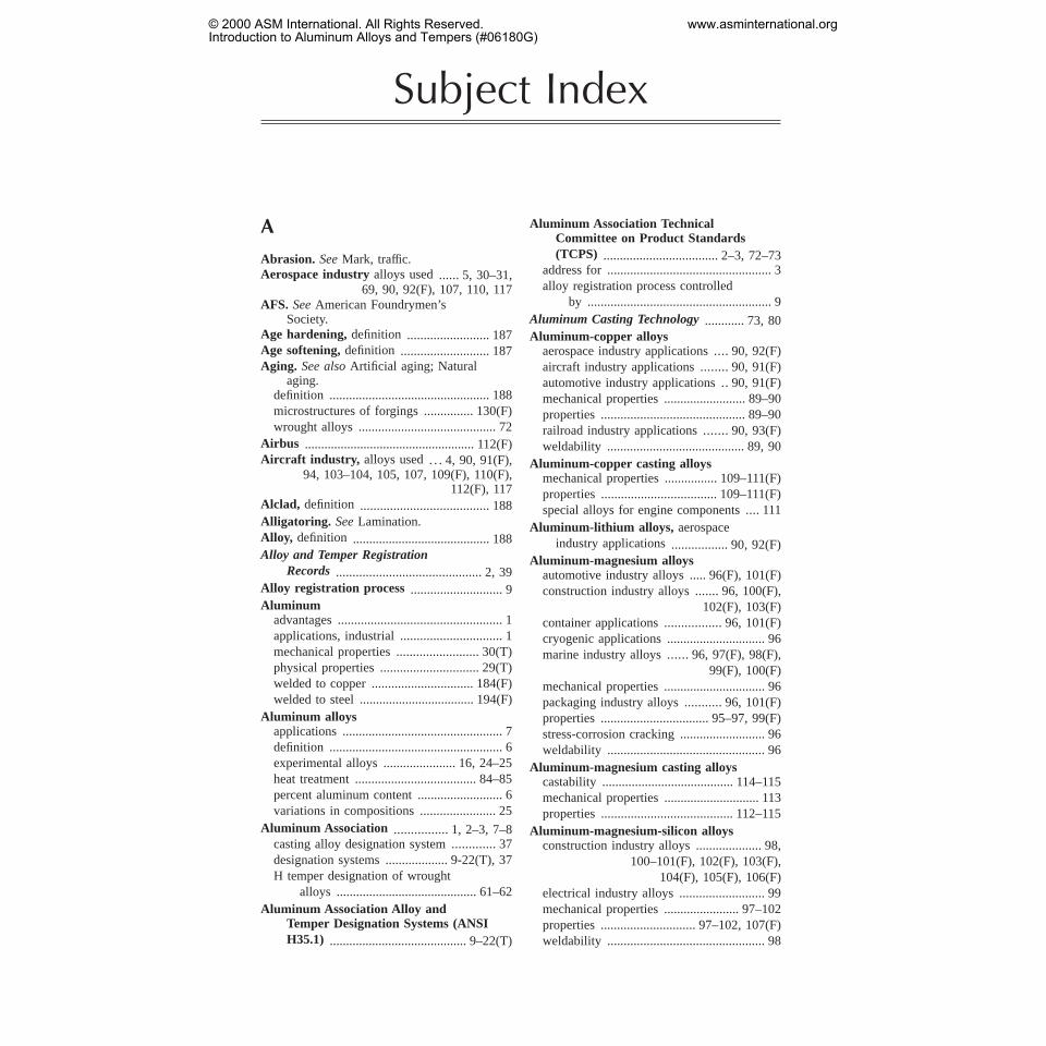
Subject Index
A
Abrasion. SeeMark, traffic.Aerospace industryalloys used...... 5,30–31,
69, 90, 92(F), 107, 110, 117AFS. SeeAmerican Foundrymen’s
Society.Age hardening,definition ......................... 187Age softening,definition ........................... 187Aging. See alsoArtificial aging; Natural
aging.definition ................................................. 188microstructures of forgings ............... 130(F)wrought alloys .......................................... 72
Airbus .................................................... 112(F)Aircraft industry, alloys used. . . 4, 90, 91(F),
94, 103–104, 105, 107, 109(F), 110(F),112(F), 117
Alclad, definition ....................................... 188Alligatoring. SeeLamination.Alloy, definition .......................................... 188Alloy and Temper Registration
Records............................................ 2, 39Alloy registration process ............................ 9Aluminum
advantages .................................................. 1applications, industrial ............................... 1mechanical properties ......................... 30(T)physical properties .............................. 29(T)welded to copper ............................... 184(F)welded to steel ................................... 194(F)
Aluminum alloysapplications ................................................. 7definition ..................................................... 6experimental alloys ...................... 16, 24–25heat treatment ..................................... 84–85percent aluminum content .......................... 6variations in compositions ....................... 25
Aluminum Association ................ 1,2–3, 7–8casting alloy designation system............. 37designation systems ................... 9-22(T), 37H temper designation of wrought
alloys ........................................... 61–62Aluminum Association Alloy and
Temper Designation Systems (ANSIH35.1) .......................................... 9–22(T)
Aluminum Association TechnicalCommittee on Product Standards(TCPS) ................................... 2–3, 72–73
address for .................................................. 3alloy registration process controlled
by ........................................................ 9Aluminum Casting Technology............ 73, 80Aluminum-copper alloys
aerospace industry applications.... 90,92(F)aircraft industry applications........ 90,91(F)automotive industry applications .. 90, 91(F)mechanical properties ......................... 89–90properties ............................................ 89–90railroad industry applications....... 90,93(F)weldability .......................................... 89, 90
Aluminum-copper casting alloysmechanical properties ................ 109–111(F)properties ................................... 109–111(F)special alloys for engine components.... 111
Aluminum-lithium alloys, aerospaceindustry applications................. 90, 92(F)
Aluminum-magnesium alloysautomotive industry alloys ..... 96(F), 101(F)construction industry alloys....... 96,100(F),
102(F), 103(F)container applications................. 96,101(F)cryogenic applications .............................. 96marine industry alloys ...... 96,97(F), 98(F),
99(F), 100(F)mechanical properties ............................... 96packaging industry alloys........... 96,101(F)properties ................................. 95–97, 99(F)stress-corrosion cracking .......................... 96weldability ................................................ 96
Aluminum-magnesium casting alloyscastability ........................................ 114–115mechanical properties ............................. 113properties ........................................ 112–115
Aluminum-magnesium-silicon alloysconstruction industry alloys .................... 98,
100–101(F), 102(F), 103(F),104(F), 105(F), 106(F)
electrical industry alloys .......................... 99mechanical properties ....................... 97–102properties ............................. 97–102, 107(F)weldability ................................................ 98
© 2000 ASM International. All Rights Reserved.Introduction to Aluminum Alloys and Tempers (#06180G)
www.asminternational.org

Aluminum-manganese alloysas automotive alloys..................... 93,94(F)beverage can application.............. 93,95(F)brazing ...................................................... 93chemical industry alloys .......................... 93construction industry alloys ..................... 93culinary industry alloys ............................ 93for heat exchangers ....................... 93, 94(F)mechanical properties ........................ 90, 93properties ............................................ 90, 93soldering ................................................... 93weldability ................................................ 93
Aluminum-silicon alloysbrazing ........................................... 93, 95(F)mechanical properties ............................... 93properties ............................................ 93–95soldering ................................................... 93weldability .......................... 93–95(F), 96(F)
Aluminum-silicon casting alloysconstruction industry alloys ................... 112for office machine housings ................... 112marine alloys .......................................... 112mechanical properties ............................. 112properties ................................................ 112
Aluminum-silicon-copper casting alloys,properties..... 111–112(F), 113(F), 114(F)
Aluminum-silicon-magnesium castingalloys, properties..... 111–112(F), 113(F),
114(F)Aluminum-silicon plus copper or
magnesium alloysmechanical properties . . 111–112(F), 113(F),
114(F)weldability .............................................. 111
Aluminum Standards and Data......1–2, 8–9,11–13(T), 22, 29, 39, 73
1998 metric standard units ......................... 8Aluminum: Technology, Applications,
and Environment (D.G. Altenpohl)..... 7,77, 87
Aluminum-tin casting alloysmechanical properties ............................. 115properties ................................................ 115
Aluminum-zinc alloysaircraft industry alloys..........103–104, 105,
109(F)mechanical properties ..................... 102–105properties .............. 102–105, 109(F), 110(F)weldability .............................................. 103
Aluminum-zinc casting alloysmechanical properties ............................. 115properties ................................................ 115
Alusuisse Alucoban .............................. 102(F)American Foundrymen’s Society
(AFS) ...................................... 37, 73, 80
American National Standard Alloy andTemper Designation Systems forAluminum .............................................. 1
American National Standards Institute(ANSI) ............................... 1, 2, 3, 22, 73
AMS, definition .......................................... 187Angularity, definition ................................ 188Angulation, definition ............................... 188Annealing
cold rolled sheet ...... 123(F), 132(F), 137(F)definition ................................................. 188hot rolled sheet .................................. 135(F)microstructure ....................... 140(F), 141(F)partial ........................................................ 40partial, definition .................................... 188plate ...................................... 135(F), 136(F)precipitates in microstructure ........... 124(F),
131(F), 138(F)sheet ................................................... 143(F)temper designation.................16-17, 18(T),
21(T), 22Annual Book of ASTM Standards............... 7Anodizing ..................................................... 27
aluminum-magnesium alloys......... 114, 115definition ................................................. 188
Anodizing sheet.SeeSheet, anodizing.ANSI. SeeAmerican National Standards
Institute.Arbor break. SeeBuckle, arbor.Arbor mark. SeeMark, arbor.Artificial aging. See alsoAging. ................ 84
casting alloys ............................................ 74of extrusion, microstructure affected
by ............................................... 139(F)microstructure of castings ... 164(F), 166(F),
167(F), 169(F), 170(F)microstructure of closed-die
forgings ...........128(F), 129(F), 130(F)microstructure of forgings ................. 152(F)microstructure of plates.......127(F), 128(F)temper designations................19–20, 21(T)wrought alloys ..... 26, 27, 60, 65–68, 70–72
As-cast condition,definition ..................... 188ASME, definition ....................................... 187Automotive industry
alloys used .. 4, 90, 91(F), 93–96(F), 98–99,101(F), 107(F), 108(F), 112–114(F)
investment casting of engines .................. 83AWS, definition .......................................... 187
BBack-end condition (coring) .. 164(F), 180(F)
definition ................................................. 188Backup roll, definition .............................. 188
226 / Introduction to Aluminum Alloys and Tempers
© 2000 ASM International. All Rights Reserved.Introduction to Aluminum Alloys and Tempers (#06180G)
www.asminternational.org

Barcold-finished, definition .......................... 189cold-finished extruded, definition.......... 189cold-finished rolled, definition ............... 189definition ................................................. 188extruded ............................................. 151(F)extruded, definition ................................ 189rolled, definition ..................................... 189saw-plate, definition ............................... 189
Base box, general,definition .................... 189Bearing applications ..................................... 5Belled edge.SeeEdge, belled.Belly, definition .......................................... 189Beryllium
as alloying element ............................. 15(T)mechanical properties ......................... 30(T)physical properties .............................. 29(T)
Billet, definition ......................................... 189Billet casting .......................................... 77–78Binder, definition ....................................... 189Bismuth
as alloying element .................. 12(T), 13(T)mechanical properties ......................... 30(T)physical properties .............................. 29(T)
Blank, definition ........................................ 189Blast cleaning,definition .......................... 189Bleed out.SeeTwo-tone.Blister
bond, definition ...................................... 189coating, definition ................................... 189core, definition ........................................ 189definition ................................................. 189
Blistering ............................................... 124(F)Block mark. SeeScratch, tension.Bloom, definition ....................................... 189Blow hole. See alsoBlister.
definition ................................................. 189Bolting, wrought alloys................................. 4Boron, as alloying element.........13(T), 15(T)Boss,definition ........................................... 189Bottom draft, definition ............................ 189Bow
definition ......................................... 189–190lateral, definition .................................... 190longitudinal, definition ........................... 190transverse, definition .............................. 190
Brazing ......................................................... 27aluminum-manganese alloys .................... 93aluminum-silicon alloys ................ 93, 95(F)commercially pure aluminum .................. 87definition ................................................. 190dip ...................................................... 180(F)of joints, microstructures ..........162–163(F)microstructure of sheet........162(F), 163(F)wrought alloys ............................................ 4
Brazing rod, definition .............................. 190
Brazing sheet ........................................ 163(F)definition ................................................. 190
Brazing wire, definition ............................ 190Bright sheet. SeeSheet, (1SBMF),
(S1SBF), and (S2SBF).Brinell hardness
casting alloys ................................. 49–57(T)wrought alloys ............................... 40–49(T)
Bristle mark. SeeMark, bristle.Broken edge.SeeEdge, broken.Broken eie,definition ................................ 190Broken matte finish, definition ................ 190Broken surface.SeeCrazing.Bruise. SeeMark, roll bruise.Buckle
arbor, definition ...................................... 190center, definition ..................................... 190definition ................................................. 190edge, definition ....................................... 190oil can.SeeBuckle, trapped.quarter, definition ................................... 190trapped, definition .................................. 190
Buffing, definition ...................................... 190Buff streak. SeeStreak.Burnishing. SeeTwo-tone.Burnish streak. SeeStreak, burnish.Burr, definition .......................................... 191Bursting strength. See alsoMullen test.
definition ................................................. 191Bus bar ................................................... 88(F)
definition ................................................. 191Butt-seam tube.SeeTube, open-seam.
CCadmium
mechanical properties ......................... 30(T)physical properties .............................. 29(T)
Camber. SeeBow, lateral.Carbon mark. SeeMark, carbon.Cast aluminum alloy, definition .................. 6Casting alloys
advantages ........................................... 34(T)alloy group ............................................... 14alloying element in greatest mean
percentage ......................................... 14alloying elements ............... 14(T), 15–16(T)applications for alloys and
tempers ............................... 108–115(F)artificial aging ........................................... 74composition ........................ 14(T), 15–16(T)corrosion .............................................. 34(T)cracking ............................................... 34(T)designation system ................. 11, 13–16(T),
32–37(T)elongations .................................................. 8
Subject Index / 227
© 2000 ASM International. All Rights Reserved.Introduction to Aluminum Alloys and Tempers (#06180G)
www.asminternational.org
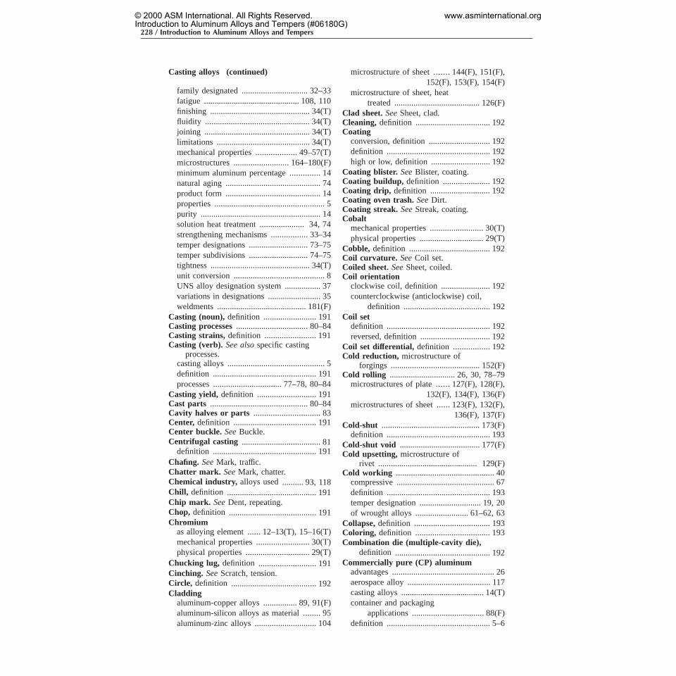
Casting alloys (continued)
family designated ............................... 32–33fatigue ............................................. 108, 110finishing ............................................... 34(T)fluidity ................................................. 34(T)joining .................................................. 34(T)limitations ............................................ 34(T)mechanical properties...................49–57(T)microstructures .......................... 164–180(F)minimum aluminum percentage .............. 14natural aging ............................................. 74product form ............................................. 14properties .................................................... 5purity ......................................................... 14solution heat treatment ..................... 34, 74strengthening mechanisms.................33–34temper designations ............................ 73–75temper subdivisions ............................ 74–75tightness ............................................... 34(T)unit conversion ........................................... 8UNS alloy designation system ................. 37variations in designations ......................... 35weldments .......................................... 181(F)
Casting (noun),definition ......................... 191Casting processes.................................. 80–84Casting strains,definition ........................ 191Casting (verb). See alsospecific casting
processes.casting alloys .............................................. 5definition ................................................. 191processes ................................ 77–78, 80–84
Casting yield, definition ............................ 191Cast parts .............................................. 80–84Cavity halves or parts ............................... 83Center, definition ....................................... 191Center buckle. SeeBuckle.Centrifugal casting ..................................... 81
definition ................................................. 191Chafing. SeeMark, traffic.Chatter mark. SeeMark, chatter.Chemical industry, alloys used.......... 93, 118Chill, definition .......................................... 191Chip mark. SeeDent, repeating.Chop, definition ......................................... 191Chromium
as alloying element ...... 12–13(T), 15–16(T)mechanical properties ......................... 30(T)physical properties .............................. 29(T)
Chucking lug, definition ........................... 191Cinching. SeeScratch, tension.Circle, definition ........................................ 192Cladding
aluminum-copper alloys ................ 89, 91(F)aluminum-silicon alloys as material ........ 95aluminum-zinc alloys ............................. 104
microstructure of sheet .......144(F), 151(F),152(F), 153(F), 154(F)
microstructure of sheet, heattreated ........................................ 126(F)
Clad sheet.SeeSheet, clad.Cleaning, definition ................................... 192Coating
conversion, definition ............................. 192definition ................................................. 192high or low, definition ............................ 192
Coating blister. SeeBlister, coating.Coating buildup, definition ...................... 192Coating drip, definition ............................ 192Coating oven trash.SeeDirt.Coating streak. SeeStreak, coating.Cobalt
mechanical properties ......................... 30(T)physical properties .............................. 29(T)
Cobble, definition ...................................... 192Coil curvature. SeeCoil set.Coiled sheet.SeeSheet, coiled.Coil orientation
clockwise coil, definition ....................... 192counterclockwise (anticlockwise) coil,
definition ......................................... 192Coil set
definition ................................................. 192reversed, definition ................................. 192
Coil set differential, definition ................. 192Cold reduction, microstructure of
forgings .......................................... 152(F)Cold rolling ............................... 26, 30, 78–79
microstructures of plate ......127(F), 128(F),132(F), 134(F), 136(F)
microstructures of sheet......123(F), 132(F),136(F), 137(F)
Cold-shut .............................................. 173(F)definition ................................................. 193
Cold-shut void ...................................... 177(F)Cold upsetting, microstructure of
rivet ............................................... 129(F)Cold working .............................................. 40
compressive .............................................. 67definition ................................................. 193temper designation ............................. 19, 20of wrought alloys ......................... 61–62, 63
Collapse,definition .................................... 193Coloring, definition ................................... 193Combination die (multiple-cavity die),
definition ............................................. 192Commercially pure (CP) aluminum
advantages ................................................ 26aerospace alloy ....................................... 117casting alloys ....................................... 14(T)container and packaging
applications .................................. 88(F)definition ................................................. 5–6
228 / Introduction to Aluminum Alloys and Tempers
© 2000 ASM International. All Rights Reserved.Introduction to Aluminum Alloys and Tempers (#06180G)
www.asminternational.org

designation system ................................... 24electrical applications .......................... 88(F)electrical properties ............................ 87, 88in wrought alloy designation
system .................................... 10(T), 11limitations ................................................. 26mechanical properties ......................... 87–88microstructure due to solidification . . 121(F)microstructures ..................... 120(F), 121(F)properties ....................................... 87–88(F)sheet metal work ...................................... 88strengthening mechanisms............25–26(T)as telescopic mirror material ........ 88,90(F)
Compressive cold working,wroughtalloys ..................................................... 67
Concavity, definition ................................. 193Concentricity, definition ........................... 193Condensation stain.SeeCorrosion,
water stain.Condenser tube,definition ....................... 193Conduit
definition ................................................. 193rigid, definition ....................................... 193
Coned-out coil.SeeTelescoping.Construction industry, alloys used .... 93, 94,
96, 98, 100–101(F), 102(F), 103(F), 104(F),105(F), 106(F), 112, 114, 116
Container and packaging industry ............ 4commercially pure aluminum ............ 88(F)
Continuous casting,microstructures... 140(F)Contour, definition .................................... 193Controlled cooling, definition .................. 193Conversion coating, can ends.See
Coating, conversion.Conversion of units .................................. 7–8Convexity, definition ................................. 193Copper
as alloying element ..... 10(T), 11, 12–13(T),14(T), 15–16(T)
as alloying element, casting alloyapplications .. 108, 109–111(F), 112(F),
113(F), 114(F)as alloying element, casting
alloys ..................................... 33(T), 34as alloying element, wrought alloy
applications........ 89–90, 91(F), 92(F),93(F)
as alloying element, wroughtalloys ............ 23,25(T), 26–27, 28, 29
mechanical properties ......................... 30(T)physical properties .............................. 29(T)welded to aluminum .......................... 184(F)
CO2 process,definition ............................. 192Core blister. SeeBlister, core.Core (for casting), definition .................... 193Core (for rolled products), definition ..... 193
Coring. SeeBack-end condition.Corner turnup, definition ......................... 193Corrosion
aluminum-copper alloys ........................... 89casting alloys ....................................... 34(T)definition ................................................. 193exfoliation ............104–105, 150(F), 152(F)exfoliation, definition ............................. 193fretting ............................................... 151(F)galvanic, definition ................................. 194intergranular, definition .......................... 194pitting .................................... 136(F), 149(F)pitting, definition .................................... 194stress-cracking, definition...................... 194water stain, definition ............................. 194
Corrosion resistancealuminum-copper alloys ........................... 89aluminum-magnesium
alloys ..................... 96, 99(F), 113–114aluminum-magnesium-silicon
alloys ..................... 97, 98, 101, 107(F)aluminum-manganese alloys .............. 90, 93aluminum-silicon alloys ......................... 112aluminum-zinc alloys ..................... 104–105commercially pure aluminum ............ 87, 88temper designation ................................... 40temper designations, wrought alloys....... 71wrought alloys ......................... 3, 27, 28, 66
Corrugating, definition ............................. 194Coupon, definition ..................................... 194Covering area,definition .......................... 194Cracking, casting alloys........................34(T)Crazing, definition ..................................... 194Crease,definition ....................................... 194Cross hatching.SeeCrazing.Crown. SeeConvexity.Cryogenic toughness,wrought alloys .......... 4Curl, definition .......................................... 194Cutoff, definition ........................................ 194
DDeep drawing,definition .......................... 194Defect,definition ........................................ 194Dendrite arm spacing (DAS),effect on
casting structure fineness.. 168(F), 169(F)Dendrites ............................................... 157(F)
of brazed joint in sheet........162(F), 163(F)in castings...............166(F), 168(F), 169(F)in sand casting ................................... 179(F)
Dendritic segregation,titanium iningot ................................ 136(F), 137(F)
Density, wrought alloys.................... 28–29(F)Dent. See alsoMark, handling.
definition ................................................. 195
Subject Index / 229
© 2000 ASM International. All Rights Reserved.Introduction to Aluminum Alloys and Tempers (#06180G)
www.asminternational.org

Dent (continued)
expansion, definition .............................. 195repeating, definition ................................ 195
Designation systems................ 1–2, 31, 32(T)capital letters used for alloys ............. 24–25casting alloys ................................. 32–37(T)casting alloys, cross reference
chart ....................................... 36–37(T)comparison of previous and current
systems ........................................ 32(T)experimental alloys ............................ 24–25temper, for wrought alloys ................. 39–40UNS alloy ................................................. 31variations .................................................. 25wrought alloys ............................... 23–32(T)
Die Casting Development Council........... 37Die casting (noun) ................................ 83–84
aluminum-magnesium alloys ................. 113aluminum-silicon alloys ......................... 112aluminum-silicon plus copper or
magnesium alloys ........................... 111compositions for commercial
uses ................................................... 35definition ................................................. 195mechanical properties .............. 53(T), 57(T)microstructure ........171(F), 172(F), 173(F),
174(F), 176(F), 177(F), 178(F), 179(F)Die casting (verb)
cold chamber, definition ......................... 195definition ................................................. 195gravity, definition ................................... 195hot chamber, definition .......................... 195pressure.See alsoLow-pressure casting
process; High-pressure molding.pressure, definition ................................. 195vs. permanent mold casting ..................... 81
Die forgings ................................................. 80Die (in casting),definition ........................ 195Die (in forging or extrusion), definition .. 195Die line, definition ..................................... 195Die number, definition .............................. 195Diffusion processes.............................. 131(F)Diffusion streak. SeeStreak, diffusion.Dimensional stability, definition .............. 196Dip brazing ........................................... 180(F)Direct castings,microstructure............131(F)Dirt, definition ........................................... 196Disc, definition ........................................... 196Double shear notch.SeeNotch, double
shear.Draft, definition ......................................... 196Drag mark. SeeRub, tool.Draw and iron-can bodies,definition ..... 196Drawing ................................................. 26, 30
definition ................................................. 196
Drawing stock, definition ......................... 196Drawn-in scratch. SeeScratch, drawn-in.Drawn product, definition ........................ 196Dropped edge.SeeEdge, dropped.Dry sand molding, definition ................... 196Dry sheet.SeeLube, low.Dry surface, definition .............................. 196Ductility
definition ................................................. 196wrought alloys .......................................... 27
Duct sheet,definition ................................ 196Dynamic recrystallization ................... 134(F)
EEaring, definition ....................................... 196Ears, definition .......................................... 197Eccentricity, definition .............................. 197Edge
band.SeeTwo-tone.belled, definition ..................................... 197broken (cracked), definition ................... 197built-up. SeeEdge, belled.damaged, definition ................................ 197dropped, definition ................................. 197liquated, definition .................................. 197rippled.SeeBuckle, edge.wavy. SeeBuckle, edge.
Elastic limit, definition .............................. 197Electrical and electronic industry
alloys used ... 88(F), 99, 106, 107, 110, 112,115–116
commercially pure aluminumapplications .................................. 88(F)
Electrical beam weldingof investment casting ........................ 181(F)of plate .................................. 158(F), 162(F)of sheet .................... 155(F), 156(F), 159(F)
Electrical conductivitycommercially pure aluminum ............ 87, 88definition ................................................. 1978xxx series ..................................... 106, 107wrought alloys ............................................ 4
Electrical resistivity, definition ................ 197Elevated temperatures
aluminum-copper alloys ........................... 89aluminum-copper casting alloys............ 109
Elongationcasting alloys ................................. 49–57(T)definition ......................................... 197–198wrought alloys ............................... 40–49(T)
Embossing,definition ................................ 198Endurance limit
casting alloys ................................. 49–57(T)definition ................................................. 198
230 / Introduction to Aluminum Alloys and Tempers
© 2000 ASM International. All Rights Reserved.Introduction to Aluminum Alloys and Tempers (#06180G)
www.asminternational.org

wrought alloys ............................... 40–49(T)Energy absorption capacity,wrought
alloys ....................................................... 4English/engineering units ............................ 8Equivalent round, definition .................... 198Expendable pattern casting,definition ... 198Experimental aluminum alloys .... 16, 24–25Explosive welding
aluminum to copper .......................... 184(F)aluminum to steel .............................. 184(F)
Extrusion ............................................... 30, 79aluminum-magnesium-silicon
alloys .............97–102, 103(F), 104(F),105(F), 106(F), 107(F), 108(F)
aluminum-zinc alloys ................ 105, 109(F)conform ..................................................... 79definition ................................................. 198direct ......................................................... 79gas tungsten arc welding ................... 161(F)indirect ...................................................... 79microstructures .......135(F), 138(F), 139(F),
141(F), 148(F), 149(F), 150(F),161(F), 151(F)
reverse ....................................................... 79Extrusion billet, definition ........................ 198Extrusion butt end defect, definition ...... 198Extrusion log, definition ........................... 198Extrusion seam,definition ........................ 198Eyehole.SeeHoliday.
FFabrication, temper designation..... 16, 57–58Fatigue
aluminum-silicon alloys ......................... 112casting alloys .................................. 108, 110definition ................................................. 198test, fayed sheet ................................. 151(F)
Fatigue limitcasting alloys ................................. 49–57(T)wrought alloys ............................... 40–49(T)
Feeder.SeeRiser.Feed in.SeeBack-end condition.Feed line.SeeStreak, grinding.Fillet, definition .......................................... 198Fin, definition ............................................. 198Finish
casting alloys .............................................. 5definition ................................................. 199
Finishing, casting alloys........................34(T)Fin stock, definition .................................. 199Fish mouthing, definition ......................... 199Flag, definition ........................................... 199Flaking, definition ..................................... 199
Flange.SeeRib.Flash, definition ......................................... 199Flash line, definition .................................. 199Flatness,definition .................................... 199Flat-rolled products .............................. 78–79Flow lines .....145(F), 172(F), 173(F), 174(F),
177(F), 178(F)definition ................................................. 199
Flow through, definition ........................... 199Fluidity, casting alloys ........................... 34(T)Foil
annealed, definition ................................ 199bright two sides, definition .................... 199chemically cleaned, definition............... 199definition ................................................. 199embossed, definition ............................... 199etched, definition .................................... 199fabrication ........................................... 78–79for food products industry ..................... 188hard, definition ....................................... 199intermediate temper, definition.............. 199matte one side (M1S), definition ........... 199mechanically grained, definition ............ 199mill finish (MF), definition .................... 200packaging applications, for food
products ................................. 88, 89(F)scratch brushed, definition ..................... 200
Foil stock. SeeReroll stock.Fold ....................................................... 145(F)
definition ................................................. 200Food products industry, alloys used for
packaging and utensils .. 88(F), 89(F), 93,95(F), 96, 101(F)
Foresmo Bridge ................................... 103(F)Forgeability, definition .............................. 200Forge casting ............................................... 84Forging ................................................... 79–80
blocker-type, definition .......................... 200closed-die, grain structure ... 128(F), 129(F),
130(F), 141(F)cold-coined, definition ............................ 200definition ................................................. 200die, definition .......................................... 200draftless, definition ................................. 200flashless, definition ................................. 200hammer, definition ................................. 200hand, definition ....................................... 200microstructures .......123(F), 124(F), 130(F),
144(F), 145(F), 146(F), 147(F),148(F), 152(F)
no-draft.SeeForging, draftless.precision, definition ................................ 200press, definition ...................................... 200rolled ring ................................................. 80rolled ring, definition ............................. 200upset, definition ...................................... 200
Subject Index / 231
© 2000 ASM International. All Rights Reserved.Introduction to Aluminum Alloys and Tempers (#06180G)
www.asminternational.org
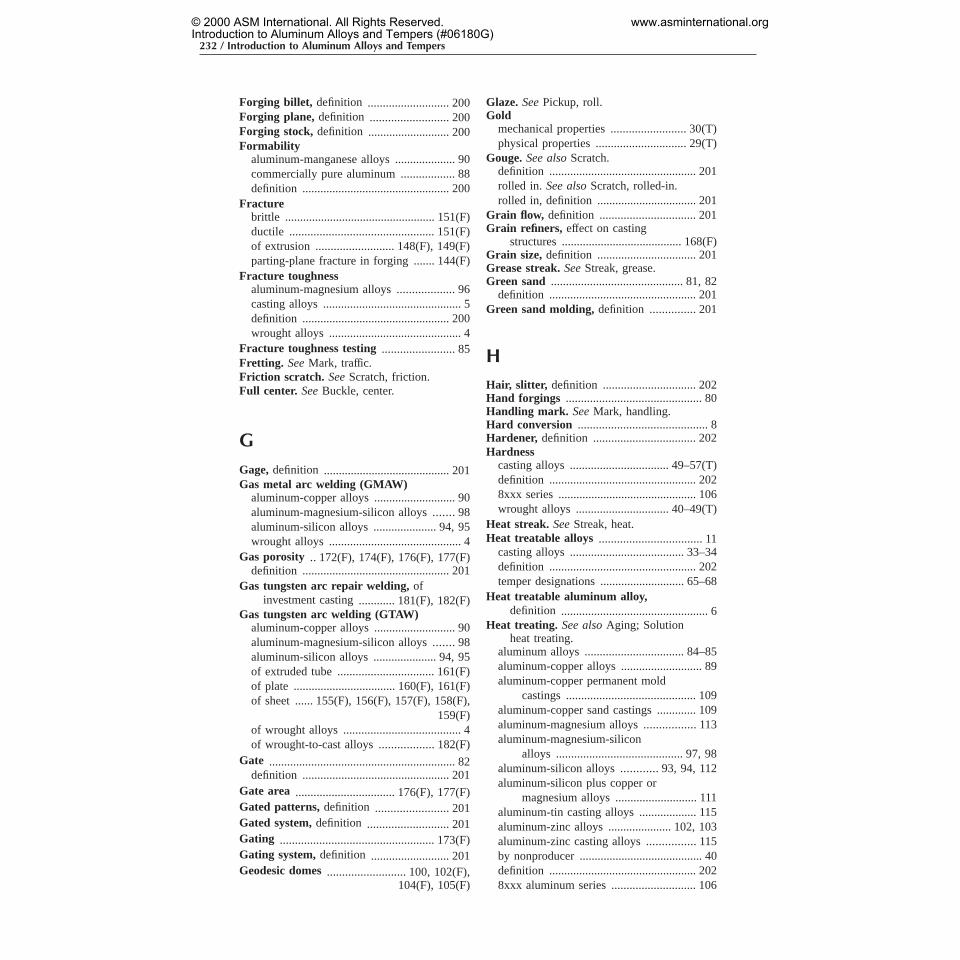
Forging billet, definition ........................... 200Forging plane, definition .......................... 200Forging stock, definition ........................... 200Formability
aluminum-manganese alloys .................... 90commercially pure aluminum .................. 88definition ................................................. 200
Fracturebrittle .................................................. 151(F)ductile ................................................ 151(F)of extrusion .......................... 148(F), 149(F)parting-plane fracture in forging ....... 144(F)
Fracture toughnessaluminum-magnesium alloys ................... 96casting alloys .............................................. 5definition ................................................. 200wrought alloys ............................................ 4
Fracture toughness testing........................ 85Fretting. SeeMark, traffic.Friction scratch. SeeScratch, friction.Full center. SeeBuckle, center.
GGage,definition .......................................... 201Gas metal arc welding (GMAW)
aluminum-copper alloys ........................... 90aluminum-magnesium-silicon alloys....... 98aluminum-silicon alloys ..................... 94, 95wrought alloys ............................................ 4
Gas porosity .. 172(F), 174(F), 176(F), 177(F)definition ................................................. 201
Gas tungsten arc repair welding,ofinvestment casting............ 181(F), 182(F)
Gas tungsten arc welding (GTAW)aluminum-copper alloys ........................... 90aluminum-magnesium-silicon alloys....... 98aluminum-silicon alloys ..................... 94, 95of extruded tube ................................ 161(F)of plate .................................. 160(F), 161(F)of sheet ...... 155(F), 156(F), 157(F), 158(F),
159(F)of wrought alloys ....................................... 4of wrought-to-cast alloys..................182(F)
Gate .............................................................. 82definition ................................................. 201
Gate area ................................. 176(F), 177(F)Gated patterns,definition ........................ 201Gated system,definition ........................... 201Gating ................................................... 173(F)Gating system,definition .......................... 201Geodesic domes.......................... 100, 102(F),
104(F), 105(F)
Glaze.SeePickup, roll.Gold
mechanical properties ......................... 30(T)physical properties .............................. 29(T)
Gouge.See alsoScratch.definition ................................................. 201rolled in. See alsoScratch, rolled-in.rolled in, definition ................................. 201
Grain flow, definition ................................ 201Grain refiners, effect on casting
structures ........................................ 168(F)Grain size, definition ................................. 201Grease streak.SeeStreak, grease.Green sand ............................................ 81, 82
definition ................................................. 201Green sand molding,definition ............... 201
HHair, slitter, definition ............................... 202Hand forgings ............................................. 80Handling mark. SeeMark, handling.Hard conversion ........................................... 8Hardener, definition .................................. 202Hardness
casting alloys ................................. 49–57(T)definition ................................................. 2028xxx series .............................................. 106wrought alloys ............................... 40–49(T)
Heat streak. SeeStreak, heat.Heat treatable alloys .................................. 11
casting alloys ...................................... 33–34definition ................................................. 202temper designations ............................ 65–68
Heat treatable aluminum alloy,definition ................................................. 6
Heat treating. See alsoAging; Solutionheat treating.
aluminum alloys ................................. 84–85aluminum-copper alloys ........................... 89aluminum-copper permanent mold
castings ........................................... 109aluminum-copper sand castings ............. 109aluminum-magnesium alloys ................. 113aluminum-magnesium-silicon
alloys .......................................... 97, 98aluminum-silicon alloys............ 93, 94, 112aluminum-silicon plus copper or
magnesium alloys ........................... 111aluminum-tin casting alloys ................... 115aluminum-zinc alloys ..................... 102, 103aluminum-zinc casting alloys ................ 115by nonproducer ......................................... 40definition ................................................. 2028xxx aluminum series ............................ 106
232 / Introduction to Aluminum Alloys and Tempers
© 2000 ASM International. All Rights Reserved.Introduction to Aluminum Alloys and Tempers (#06180G)
www.asminternational.org
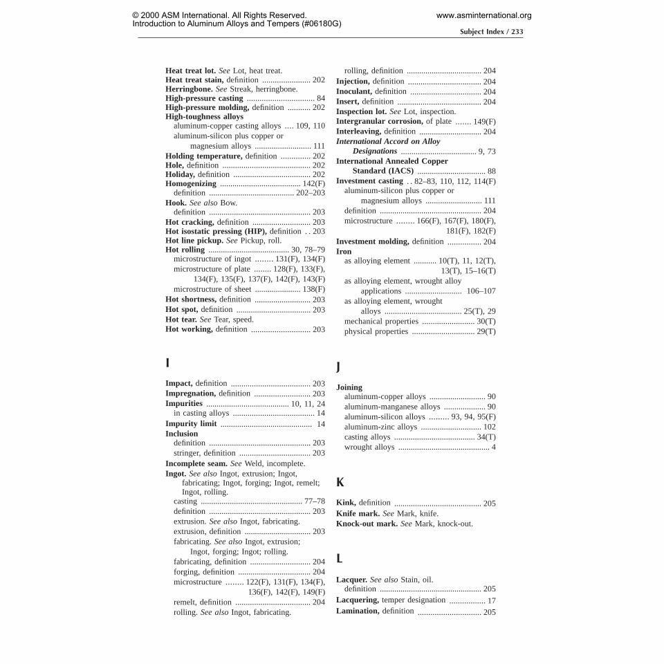
Heat treat lot. SeeLot, heat treat.Heat treat stain, definition ....................... 202Herringbone. SeeStreak, herringbone.High-pressure casting ................................ 84High-pressure molding,definition ........... 202High-toughness alloys
aluminum-copper casting alloys.... 109, 110aluminum-silicon plus copper or
magnesium alloys ........................... 111Holding temperature, definition .............. 202Hole, definition .......................................... 202Holiday, definition ..................................... 202Homogenizing ....................................... 142(F)
definition ......................................... 202–203Hook. See alsoBow.
definition ................................................. 203Hot cracking, definition ............................ 203Hot isostatic pressing (HIP),definition . . 203Hot line pickup. SeePickup, roll.Hot rolling ....................................... 30, 78–79
microstructure of ingot ........131(F), 134(F)microstructure of plate........128(F), 133(F),
134(F), 135(F), 137(F), 142(F), 143(F)microstructure of sheet ...................... 138(F)
Hot shortness,definition ........................... 203Hot spot, definition .................................... 203Hot tear. SeeTear, speed.Hot working, definition ............................ 203
IImpact, definition ...................................... 203Impregnation, definition ........................... 203Impurities ........................................ 10, 11, 24
in casting alloys ....................................... 14Impurity limit ............................................ 14Inclusion
definition ................................................. 203stringer, definition .................................. 203
Incomplete seam.SeeWeld, incomplete.Ingot. See alsoIngot, extrusion; Ingot,
fabricating; Ingot, forging; Ingot, remelt;Ingot, rolling.
casting ................................................. 77–78definition ................................................. 203extrusion.See alsoIngot, fabricating.extrusion, definition ................................ 203fabricating.See alsoIngot, extrusion;
Ingot, forging; Ingot; rolling.fabricating, definition ............................. 204forging, definition ................................... 204microstructure ........122(F), 131(F), 134(F),
136(F), 142(F), 149(F)remelt, definition .................................... 204rolling. See alsoIngot, fabricating.
rolling, definition .................................... 204Injection, definition ................................... 204Inoculant, definition .................................. 204Insert, definition ........................................ 204Inspection lot. SeeLot, inspection.Intergranular corrosion, of plate .......149(F)Interleaving, definition .............................. 204International Accord on Alloy
Designations.................................... 9, 73International Annealed Copper
Standard (IACS) ................................. 88Investment casting . . 82–83, 110, 112, 114(F)
aluminum-silicon plus copper ormagnesium alloys ........................... 111
definition ................................................. 204microstructure ........166(F), 167(F), 180(F),
181(F), 182(F)Investment molding, definition ................ 204Iron
as alloying element ........... 10(T), 11, 12(T),13(T), 15–16(T)
as alloying element, wrought alloyapplications ........................... 106–107
as alloying element, wroughtalloys ..................................... 25(T), 29
mechanical properties ......................... 30(T)physical properties .............................. 29(T)
J
Joiningaluminum-copper alloys ........................... 90aluminum-manganese alloys .................... 90aluminum-silicon alloys ......... 93, 94,95(F)aluminum-zinc alloys ............................. 102casting alloys ....................................... 34(T)wrought alloys ............................................ 4
KKink, definition .......................................... 205Knife mark. SeeMark, knife.Knock-out mark. SeeMark, knock-out.
L
Lacquer. See alsoStain, oil.definition ................................................. 205
Lacquering, temper designation................. 17Lamination, definition .............................. 205
Subject Index / 233
© 2000 ASM International. All Rights Reserved.Introduction to Aluminum Alloys and Tempers (#06180G)
www.asminternational.org

Lap. SeeFold.Lateral bow. SeeBow, lateral.Layout sample,definition ......................... 205Lead
as alloying element .................. 12(T), 13(T)mechanical properties ......................... 30(T)physical properties .............................. 29(T)
Leveler chatter. SeeMark, chatter (rollor leveler).
Leveler mark. SeeDent, repeating.Leveler streak. SeeStreak, leveler.Leveling
definition ................................................. 205roller, definition ...................................... 205stretcher, definition ................................. 205tension, definition ................................... 205thermal, definition .................................. 205
Light poles .................................... 101, 107(F)Line
flow, definition ........................................ 205looper, definition .................................... 205Lueders, definition .................................. 205weld. SeeSeam, extrusion.
Liner, definition ......................................... 205Liquated edge.SeeEdge, liquated.Liquation, definition .................................. 205Liquefied natural gas tankage .................... 4Lithium
as alloying element, wrought alloyapplications ................ 106–107, 110(F)
as alloying element, wrought alloys ........ 29mechanical properties ......................... 30(T)physical properties .............................. 29(T)
Lock, definition .......................................... 206Log. SeeExtrusion log.Longitudinal bow. SeeBow,
longitudinal.Longitudinal direction, definition ............ 206Longitudinal orientation, definition ............ 6Long transverse direction.See also
Longitudinal direction.definition ................................................. 206
Long transverse orientation,definition . . 6–7Looper line. SeeLine, looper.Loose wrap.SeeWrap, loose.Lost foam casting,definition .................... 206Lot
heat treat, definition ............................... 206inspection, definition .............................. 206
Low-pressure casting process.See alsoVacuum casting process.
definition ................................................. 206Lube
high, definition ....................................... 206low, definition ......................................... 206
Lueders line. SeeLine, Lueders.Lug ........................................... 146(F), 147(F)
M
Machinabilityaluminum-tin alloys ................................ 115aluminum-zinc alloys ............................. 115
Magnesiumas alloying element ..... 10(T), 11, 12–13(T),
14(T), 15–16(T)as alloying element, casting alloy
applications.......... 111–112(F), 113(F),114(F), 115
as alloying element, castingalloys ..................................... 33(T), 34
as alloying element, wrought alloyapplications .......... 95–101(F), 102(F),
103(F), 104(F), 105(F), 106(F),107(G), 108(F)
as alloying element, wrought alloys ....... 23,25(T), 26, 27–28, 29
mechanical properties ......................... 30(T)physical properties .............................. 29(T)
Magnesium silicide ................. 152(F), 159(F)in castings .......................................... 170(F)in wrought alloys.......10(T), 11, 23, 26, 28
Magnetic levitation (Mag-Lev)train .............................. 100–101, 106(F)
Manganeseas alloying element ..... 10(T), 11, 12–13(T),
15–16(T)as alloying element, wrought alloy
applications ......... 90, 93, 94(F), 95(F)as alloying element, wrought alloys ....... 23,
25(T), 26, 27mechanical properties ......................... 30(T)physical properties .............................. 29(T)
Marine industry, alloys used......... 96,97(F),98(F), 99(F), 100(F), 112, 113–114, 117
Markarbor, definition ...................................... 207bearing, definition .................................. 207bite, definition ........................................ 207bristle, definition .................................... 207carbon, definition .................................... 207chatter (roll or leveler), definition ......... 207definition ................................................. 207drag.SeeRub, tool.edge follower, definition ........................ 207handling, definition ................................ 207heat treat contact, definition.................. 207inclusion.See alsoInclusion, stringer.inclusion, definition ................................ 207knife, definition ...................................... 207knockout ................................................... 83knock-out, definition .............................. 207
234 / Introduction to Aluminum Alloys and Tempers
© 2000 ASM International. All Rights Reserved.Introduction to Aluminum Alloys and Tempers (#06180G)
www.asminternational.org

leveler chatter.SeeMark, chatter (rollor leveler).
metal-on-roll.SeeDent, repeating.mike, definition ...................................... 207pinch.SeeCrease.roll, definition ................................. 207–208roll bruise.See alsoMark, roll.roll bruise, definition .............................. 208roll skid, definition ................................. 208rub, definition ......................................... 208snap.See alsoMark, snap.snap, definition ....................................... 208stop, definition.See alsoMark, snap.....208stretcher jaw, definition .......................... 208tab.SeeBuckle, arbor.tail. SeeMark, roll bruise.take-up.SeeScratch, tension.traffic, definition ..................................... 208whip, definition ...................................... 208
Master alloy. SeeHardener.Mean diameter, definition ........................ 208Mechanical properties,definition ............ 208Melting temperature, wrought alloys ........ 3Metallography and Microstructures....... 119Metric/International Standard units .......... 8Microporosity, definition .......................... 208Microscopy .................................................... 7Microstructure, of alloys .................. 119–184Mike mark. SeeMark, mike.Minimum residual stress (MRS),
definition ..................................... 208–209Mismatch, definition ................................. 209Modulus in tension, wrought
alloys ......................................... 40–49(T)Modulus of elasticity
casting alloys ................................. 49–57(T)definition ................................................. 209measurement method (ASTM E 111)..... 30wrought alloys.............29–30(T), 40–49(T)
Mold, definition ......................................... 209Mold cavity, definition .............................. 209Molybdenum
mechanical properties ......................... 30(T)physical properties .............................. 29(T)
Mottling, pressure, definition ................... 209Mullen test, definition ............................... 209
NNailing, wrought alloys................................. 4Natural aging. See alsoAging. .................. 84
casting alloys ............................................ 74temper designations ...................... 19, 21(T)wrought alloys ......... 26, 27, 28, 59, 60, 65,
66, 68
Necking ................................................. 151(F)Nick
extrusions.SeeMark, handling.rolled products.SeeScratch.
Nickelas alloying element ................ 10, 12–13(T),
15–16(T)as alloying element, wrought alloy
applications ........................... 106–107mechanical properties ......................... 30(T)physical properties .............................. 29(T)
Nondestructive testing,definition ............ 209Non-Ferrous Founders’ Society
(NFFS) ................................................. 37Nonfill, definition ....................................... 209Non-heat-treatable alloy
casting alloys ...................................... 33–34definition ................................................. 209H temper subdivisions..................60–64(T)slab casting ............................................... 78strip casting .............................................. 78temper designations, wrought alloys....... 58wrought alloys ............................. 26, 27, 28
Notch, double shear,definition ................ 209
OOff gage,definition .................................... 209Offset, definition ................................ 209–210Oil and petroleum industry, alloys
used.......................................... 99, 100(F)Oil stain. SeeStain, oil.Orange peel,definition ............................. 210Oscillation. See alsoTelescoping.
definition ................................................. 210Out-of-register, definition ......................... 210Ovalness.SeeQuality.Overaging
microstructure .................................... 124(F)temper designation ................................... 20wrought alloys .................................... 68, 71
Oxide discoloration. SeeStain, heattreat.
Oxide stringers ..................................... 134(F)
PPackaging industry, alloys used.............. 118Pack rolling, definition ............................. 210Painting, temper designation...................... 17Parent coil, definition ................................ 210Parent plate, definition ............................. 210
Subject Index / 235
© 2000 ASM International. All Rights Reserved.Introduction to Aluminum Alloys and Tempers (#06180G)
www.asminternational.org
Partial annealing. SeeAnnealing, partial.Parting line. See alsoProfile, stepped
extruded.definition ................................................. 210
Pattern, definition ...................................... 210Patterned sheet.SeeEmbossing.Peening .................................................. 152(F)Permanent mold casting alloys,
mechanical properties ..............51–53(T),55–56(T)
Permanent mold casting (noun)microstructure ........165(F), 166(F), 167(F),
175(F), 179(F), 180(F)heat treatable .......................................... 109
Permanent mold casting (verb) ..........80–81aluminum-magnesium alloys ................. 113aluminum-silicon alloys ......................... 112aluminum-silicon plus copper or
magnesium alloys ........................... 111aluminum-tin alloys ................................ 115aluminum-zinc casting alloys ................ 115definition ................................................. 210
Permanent solid castings,microstructure................... 166(F), 170(F)
Physical properties,definition .................. 211Pickoff, definition ....................................... 211Pickup
definition ................................................. 211repeating.SeeDent, repeating.roll, definition. See alsoStreak,
coating. ........................................... 211Pinch mark. SeeCrease.Pinhole, definition ...................................... 211Pipe
definition ................................................. 211drawn, definition ..................................... 211extruded, definition ................................. 211seamless, definition ................................ 211structural, definition ............................... 211
Piping. SeeBack-end condition.Pit, definition .............................................. 211Pitting. SeeCorrosion.Plate
alclad, definition ..................................... 211definition ................................................. 211fabrication ........................................... 78–79microstructures .......124(F), 127(F), 129(F),
132(F), 133(F), 134(F), 135(F), 136(F),137(F), 142(F), 143(F), 149(F), 158(F),
160(F), 161(F), 162(F)Plate circle, definition .............................. 211Polarized light
effect on annealed plate.......135(F), 136(F)effect on cold rolled sheet . . . 136(F), 137(F)effect on extruded tube.....................141(F)effect on extrusion ............................. 135(F)
effect on ingot ................................... 142(F)effect on plate microstructure ...........142(F)
Polygonization ...................................... 124(F)extruded tube ..................................... 141(F)
Pop (solvent),definition ............................ 211Porosity, definition ..................................... 211Precipitation hardening. See also
Aging. ................................................... 84temper designation ................................... 20wrought alloys ........... 26, 27, 28, 60, 65–66
Precipitation heat treating. SeeAging.Precision casting ................................... 82–83Preheating,definition ................................ 211Pressure mottling.SeeMottling,
pressure.Pressure welding .................................. 154(F)Product forms, identified by temper
designation............................................ 40Profile
class 1 hollow extruded,definition ......................................... 212
class 2 hollow extruded,definition ......................................... 212
class 3 hollow extruded,definition ......................................... 212
cold-finished, definition .......................... 212cold-finished extruded, definition.......... 212cold-finished rolled, definition ............... 212definition ................................................. 212drawn, definition .................................... 212extruded, definition ................................ 212flute hollow, definition ........................... 212helical extruded, definition.................... 212hollow, definition .................................... 212lip hollow, definition .............................. 212pinion hollow, definition ........................ 212rolled, definition ..................................... 212semihollow, definition ............................ 212solid, definition ....................................... 212stepped extruded, definition ................... 212streamline hollow, definition .................. 213structural, definition ............................... 213tapered extruded, definition................... 213
Pure aluminum. SeeCommercially purealuminum.
QQuality, definition ...................................... 213Quarter buckle. SeeBuckle, quarter.Quenching ....................................... 40, 84, 85
casting alloys ............................................ 74definition ................................................. 213of dies ....................................................... 85
236 / Introduction to Aluminum Alloys and Tempers
© 2000 ASM International. All Rights Reserved.Introduction to Aluminum Alloys and Tempers (#06180G)
www.asminternational.org

modifications identified by temperdesignations ...................................... 68
wrought alloys ............................. 70, 71, 72Quenching crack,definition ..................... 213
RRadiographic inspection,definition ........ 213Radiography, definition ............................ 213Rail transportation industry, alloys
used ............................................. 117–118Razor streak. SeeInclusion, stringer.RCS, definition .......................................... 213Rear-end condition.SeeBack-end
condition.Recommendation: International
Designation System for WroughtAluminum and Wrought AluminumAlloys ...................................................... 2
Recrystallizationdynamic ............................................. 134(F)microstructure of closed-die
forgings ......................... 128(F), 130(F)microstructure of extrusions............138(F),
150(F)microstructure of plate ...................... 134(F)microstructure of sheet .......123(F), 131(F),
132(F), 136(F), 137(F)Recycling
casting alloy 332.0 from scrap.............. 112wrought alloys ............................................ 4
Redraw rod, definition .............................. 213References......................................... 185–186Refined aluminum, definition .................. 213Reflector sheet,definition ......................... 213Registration process,of alloys .................... 9Reheating,definition ................................. 213Reoil, definition .......................................... 214Reroll stock, definition .............................. 214Residual stresses
minimized by quenching .......................... 68temper designations ............................ 67–68
Resistance spot welding.........153(F), 154(F)Reynolds Wrap ................................ 88, 89(F)Rib, definition ............................................ 214Riser ............................................................. 82
definition ................................................. 214Riser gating, definition ............................. 214Rivet. SeeWire, cold heading.Rod
alclad, definition ..................................... 214cold-finished, definition .......................... 214cold-finished extruded, definition.......... 214cold-finished rolled, definition .............. 214cold-heading, definition .......................... 214definition ................................................. 214
extruded, definition ................................ 214rivet. SeeRod, cold-heading.rolled, definition ..................................... 214
Roll chatter. SeeMark, chatter (roll orleveler).
Rolled-in metal, definition ........................ 214Rolled-in scratch. SeeScratch, rolled-in.Rolled-over edge.SeeEdge, liquated.Rolled ring. SeeForging, rolled ring.Roll grind, definition ................................. 214Rolling coating. SeeStreak, coating.Rolling slab, definition .............................. 214Roll mark. SeeMark, roll.Roll pickup. SeePickup, roll.Roofing sheet,definition ........................... 215Roping, definition ...................................... 215Roundness,definition ................................ 215Rub mark. SeeMark, rub.Rub (tool), definition ................................. 215Runner, definition ...................................... 215Runner system,definition ........................ 215
SSample,definition ...................................... 215Sand casting .......................................... 81–82
aluminum-magnesium alloys ................. 113aluminum-silicon alloys ......................... 112aluminum-silicon plus copper or
magnesium alloys ........................... 111aluminum-tin casting alloys ................... 115aluminum-zinc casting alloys ................ 115vs. permanent mold casting ............... 81, 82
Sand casting alloys,mechanicalproperties.................. 49–51(T), 53–55(T)
Sand castingsdefinition ................................................. 215heat treatable .......................................... 109microstructure ........164(F), 167(F), 168(F),
179(F), 180(F)Sand mold,definition ................................ 215Saw-plate bar.SeeBar, saw-plate.Scalping,definition .................................... 215Scratch. See alsoMark, handling.
definition ................................................. 215drawn-in, definition ................................ 215friction, definition ................................... 215handling, definition.See alsoMark,
rub. .................................................. 215machine, definition ................................. 215oscillation, definition .............................. 215oven, definition ....................................... 216rolled-in, definition ................................. 216slippage.SeeScratch, tension.tension, definition ................................... 216
Subject Index / 237
© 2000 ASM International. All Rights Reserved.Introduction to Aluminum Alloys and Tempers (#06180G)
www.asminternational.org

Seam defect,definition .............................. 216Seam (extrusion).See alsoWeld,
incomplete.definition ................................................. 216
Seamless,definition ................................... 216Section number,definition ....................... 216Sensitization ................................................ 28
to stress-corrosion cracking ..................... 64Serpentine weave.SeeSnaking.Shape,definition ........................................ 216Shear strength
casting alloys ................................. 49–57(T)definition ................................................. 216wrought alloys ............................... 40–49(T)
Sheetalclad, definition ..................................... 216aluminum welded to copper.............184(F)aluminum welded to steel ................. 184(F)anodizing, definition ............................... 216clad, definition ........................................ 217coiled circles, definition ......................... 217coiled cut to length, definition ............... 217coiled, definition ..................................... 217definition ................................................. 216embossed, temper designation ................. 64fabrication ........................................... 78–79flat circles, definition .............................. 217flat, definition ......................................... 217microstructures .......123(F), 124(F), 125(F),
126(F), 129(F), 131(F), 132(F), 136(F),138(F), 143(F), 144(F), 151(F), 152(F),154(F), 155(F), 157(F), 158(F), 159(F),
162(F), 163(F)mill finish (MF), definition .................... 217one-sided bright mill finish (1SBMF),
definition ......................................... 217painted, definition ................................... 217pattern, temper designations...............64(T)standard one-side bright finish
(S1SBF), definition ........................ 217standard two sides bright finish
(S2SBF), definition ........................ 217temper designation .............................. 20(T)
Sheet stock.SeeReroll stock.Shell molding, definition ........................... 217Shell mold process,definition .................. 217Short transverse direction,definition ..... 217Short transverse orientation,definition ...... 7Shrinkage .............................................. 146(F)
definition ................................................. 217Side crack.SeeEdge, broken (cracked).Side set,definition ..................................... 217Silicon
as alloying element ..... 10(T), 11, 12–13(T),14(T), 15–16(T)
as alloying element, casting alloyapplications .. 108, 111–112(F), 113(F),
114(F)as alloying element, casting
alloys ..................................... 33(T), 34as alloying element, wrought alloy
applications . . 93-95(F), 96(F), 97–102,103(F), 104(F), 105(F),106(F), 107(F), 108(F)
as alloying element, wrought alloys ....... 23,25(T), 26, 27, 28, 29
content effect on castability ....................... 5mechanical properties ......................... 30(T)physical properties .............................. 29(T)
Silveras alloying element ............................. 15(T)mechanical properties ......................... 30(T)physical properties .............................. 29(T)
Skip, definition ........................................... 217Slab casting ................................................. 78Slippage scratch.SeeScratch, tension.Slitter hair. SeeHair, slitter.Sliver, definition ......................................... 217Sludge ............171(F), 172(F), 173(F), 174(F)Slug, definition ........................................... 217Smudge,definition ..................................... 218Smut. SeeSmudge.Snaking, definition .................................... 218Soft conversion ............................................. 8Soldering ...................................................... 27
aluminum-manganese alloys .................... 93aluminum-silicon alloys ........................... 93commercially pure aluminum .................. 87wrought alloys ............................................ 4
Solid-solution melting ......................... 151(F)Solution heat treating ................................ 84
casting alloys ...................................... 34, 74definition ................................................. 218microstructure of castings ... 164(F), 165(F),
166(F), 167(F), 169(F), 170(F),180(F), 181(F)
microstructure of closed-dieforgings ...........128(F), 129(F), 130(F)
microstructure of forgings . . . 130(F), 152(F)microstructure of plates ..................... 127(F)microstructure of rivets ..................... 129(F)microstructure of sheet .......123(F), 125(F),
126(F)temper designations .... 17, 19–20, 21(T), 59wrought alloys ... 11, 26, 27, 28, 60, 66, 68,
70, 71, 72Solution strengthening ............................... 26Specification limits, definition ...................... 6Specimen,definition .................................. 218
238 / Introduction to Aluminum Alloys and Tempers
© 2000 ASM International. All Rights Reserved.Introduction to Aluminum Alloys and Tempers (#06180G)
www.asminternational.org

Speed crack.SeeTear, speed.Speed tear.SeeTear, speed.Spheroidization .................................... 131(F)Splice,definition ........................................ 218Spot (lube),definition ............................... 218Spruce Goose................................ 100, 105(F)Sprue, definition ........................................ 218Squareness,definition ............................... 218Squeeze casting................... 84, 108–109, 111
definition ................................................. 218Squeeze/forge casting............................... 111Stabilizing .................................................... 40
definition ................................................. 218microstructure of castings .... 165(F), 167(F)temper designations ........................... 17, 20wrought alloys .................................... 66, 68
Stainheat treat, definition ............................... 218oil, definition .......................................... 218saw lubricant, definition ......................... 218water.SeeCorrosion, water stain.
Starvation, definition ................................ 218Steel,welded to aluminum ................... 184(F)Sticking, definition .................................... 218Straightness,definition ............................. 218Strain, definition ........................................ 218Strain-hardenable aluminum alloy,
definition ................................................. 6Strain hardening
aluminum-magnesium alloys ................... 96aluminum-manganese alloys .................... 93commercially pure aluminum ............ 11, 87definition ................................................. 219H temper subdivisions for
non-heat-treatable alloys .......60–64(T)temper designations ......... 17, 18, 22, 58–59wrought alloys .......................................... 11
Streakbearing, definition .................................. 219bright, definition ..................................... 219buff, definition ........................................ 219coating, definition ................................... 219cold. SeeStreak, heat.diffusion, definition ................................ 219dirt, definition ......................................... 219grease, definition .................................... 219grinding, definition ................................. 219heat, definition ........................................ 219herringbone, definition ........................... 219leveler, definition .................................... 219mill buff. SeeStreak, roll.pickup.SeeStreak, coating.roll, definition ......................................... 219(stripe), definition ................................... 219structural, definition ............................... 219
Streak burnish, definition ........................ 219
Strength, casting alloys ................................. 5Strength/weight ratio, wrought alloys ......... 4Stress,definition.See alsoResidual
stress. .................................................. 220Stress-corrosion cracking (SCC).
See alsoCorrosion,stress-cracking ............... 104–105, 147(F)
wrought alloys .......................................... 28Stress relieving ............................................ 40
definition ................................................. 220microstructure of cold rolled
plate ........................................... 134(F)microstructure of cold rolled
sheet ........................................... 136(F)temper designation .............................. 21(T)wrought alloys .......................................... 65wrought alloys, temper
designations ................................ 67–68Stretcher strain. SeeLine, Lueders.Stretching ........................................ 26, 71, 72
microstructures of plates ......127(F), 128(F)microstructures of sheets ................... 126(F)wrought alloys .......................................... 67
Striation, definition ................................... 220Strip, definition .......................................... 220Strip casting ................................................ 78Structural streak. SeeStreak, structural.Suck-in, definition ..................................... 220Surface tear,definition ............................. 220
TTail mark. SeeMark, roll bruise.Tear, speed............................................ 180(F)
definition ................................................. 220Tear testing .................................................. 85Telescopic mirrors, of commercially
pure aluminum .......................... 88, 90(F)Telescoping,See alsoOscillation.
definition ................................................. 220Temper
annealed ................. 16–17, 18(T), 21(T), 22annealed, casting alloys.....................73–74annealing treatments ................................. 58artificially aged ....................... 19–20, 21(T)cold worked ........................................ 19, 20corrosion resistant designations ............... 71definition ................................................. 220designating residual stress relief of heat
treated products .......................... 67–68designation identifying additional cold
work between quenching andaging ................................................. 70
designations, for wrought alloys ........ 39–40designations identifying modifications
in quenching ..................................... 68
Subject Index / 239
© 2000 ASM International. All Rights Reserved.Introduction to Aluminum Alloys and Tempers (#06180G)
www.asminternational.org

Temper (continued)
designations indicating heat treatmentby user ........................................ 68–70
designation systems ............. 1, 2, 16–22(T),57–73(T)
fabricated ...................................... 16, 57–58fabricated, casting alloys .......................... 73for aluminum pattern sheet ................. 20(T)for casting alloys ................................ 73–75for wrought alloys ......................... 57–73(T)heat treatable alloys subdivisions of T
temper ......................................... 65–68identifying cold work following aging .... 70lacquered ................................................... 17natural aging ................................. 19, 21(T)overaged ................................................... 20painted ...................................................... 17precipitation hardened .............................. 20solution heat treated ... 17, 19–20, 21(T), 59special or premium properties
designated ................................... 71–73stabilized ............................................ 17, 20strain hardening ............... 17, 18, 22, 58–59stress relieved ...................................... 21(T)subdivisions of designation
system .................................... 17–22(T)subdivisions of H temper for
non-heat-treatable alloys .......60–64(T)tensile strength ......................... 18(T), 19(T)thermal treatment ............................... 59–60thermal treatment, casting alloys ............. 74thermal treatment for stability..... 17,19–20understanding importance of
designations ...................................... 76Temper designation system..............9–22(T)Tempers for Aluminum and Aluminum
Alloy Products(Registration RecordsSeries) ............................................ 73, 75
Tensile strengthcasting alloys ................................. 49–57(T)definition ................................................. 220temper designations ................. 18(T), 19(T)wrought alloys ............................... 40–49(T)
Tension scratch.SeeScratch, tension.Test directions,definition ............................. 6Thermal conductivity, wrought alloys........ 3Thermal treatment, temper
designations................. 17,19–20, 59–60Thixocasting ........................... 84, 111, 112(F)
microstructure of parts ..................... 170(F)Tightness,of casting alloys...................34(T)Tin
as alloying element ........... 10(T), 11, 14(T),15(T), 16(T)
as alloying element, casting alloyapplications ..................................... 115
as alloying element, castingalloys ..................................... 33(T), 34
mechanical properties ......................... 30(T)physical properties .............................. 29(T)
Titaniumas alloying element ...... 12–13(T), 15–16(T)dendritic segregation in
ingot .............................. 136(F), 137(F)mechanical properties ......................... 30(T)physical properties .............................. 29(T)
Tolerance,definition .................................. 220Tool, definition ........................................... 220Tooling pad. SeeChucking lug.Tooling plate, definition ............................ 220Torn surface, definition ............................ 220Traffic mark, definition ....................220–221Transportation industry. See
Automotive industry.Transverse bow.SeeBow, transverse.Transverse direction,definition ............... 221Tread plate, definition ............................... 221Trim inclusion, definition ......................... 221Tube
alclad, definition ..................................... 221arc-welded, definition ............................. 221brazed, definition .................................... 221butt-welded, definition ........................... 221definition ................................................. 221drawn, definition .................................... 221embossed, definition ............................... 221extruded, definition ................................ 221extruded, weldment ........................... 161(F)finned, definition .................................... 221fluted, definition ..................................... 221heat-exchanger, 93, 94(F)heat-exchanger, definition ...................... 221helical-welded, definition ....................... 221lap-welded, definition ............................. 222lock-seam, definition .............................. 222microstructure of extrusion ............... 141(F)open-seam, definition ............................. 222redraw.SeeTube stock.seamless, definition ................................ 222sized, definition ...................................... 222stepped drawn, definition ....................... 222structural, definition ............................... 222welded, definition ................................... 222
Tube bloom. SeeTube stock.Tube stock,definition ................................ 222Tubing. See alsoTube.
electrical metallic, definition .................. 222Tubular conductor, definition .................. 222Twist, definition ......................................... 222Two-tone, definition .................................. 222
240 / Introduction to Aluminum Alloys and Tempers
© 2000 ASM International. All Rights Reserved.Introduction to Aluminum Alloys and Tempers (#06180G)
www.asminternational.org
UUltimate shearing strength
casting alloys ................................. 49–57(T)wrought alloys ............................... 40–49(T)
Ultimate tensile strength.See alsoTensile strength.
aluminum-copper alloys ........................... 89aluminum-copper casting alloys............ 110aluminum-magnesium alloys........... 96, 113aluminum-magnesium-silicon alloys....... 98aluminum-manganese alloys .................... 90aluminum-silicon alloys ................... 93, 112aluminum-silicon plus copper or
magnesium alloys ........................... 111aluminum-tin alloys ................................ 115aluminum-zinc alloys ..................... 102, 115casting alloys ................................. 49–57(T)commercially pure aluminum .................. 878xxx aluminum series ............................ 106wrought alloys......................40–49(T), 106
Unified Numbering System (UNS) alloydesignation system.............................. 31
for casting alloys ...................................... 37Unit conversion ......................................... 7-8Units ............................................................ 7-8UNS number ............................................... 31
VVacuum casting process,definition ......... 223Vanadium, as alloying element .. 12(T), 15(T)Variations
castings alloys .......................................... 35in alloy compositions ............................... 25
Vent mark, definition ................................ 223Voids ..............152(F), 174(F), 177(F), 180(F)
WWater stain. SeeCorrosion, water stain.Wavy edge.SeeBuckle edge.Weave.SeeOscillation.Web, definition ........................................... 223Weld, incomplete,definition ..................... 223Weldability
aluminum-copper alloys ........................... 89aluminum-magnesium alloys ................... 96aluminum-magnesium-silicon alloys....... 98aluminum-manganese alloys .................... 93aluminum-silicon alloys ..... 93–95(F), 96(F)aluminum-silicon plus copper or
magnesium alloys ........................... 111
aluminum-zinc alloys ............................. 103wrought alloys ............................................ 4
Welding, definition .................................... 223Welding rod, definition ............................. 223Welding wire, definition ........................... 223Weld line. SeeSeam, extrusion.Weldments
aluminum-copper, explosivewelding ...................................... 184(F)
aluminum-steel, explosivewelding ...................................... 184(F)
casting alloys ..................................... 181(F)of wrought alloys ...................... 153–162(F)
Wettability test, definition ........................ 223Whip marks. SeeMark, whip.Whisker. SeeHair, slitter.Wire
alclad, definition ............................. 223–224definition ................................................. 223cold-heading, definition .......................... 224cold-heading, microstructure ............. 129(F)cold-heading, wrought alloys ..................... 4drawn, definition .................................... 224extruded, definition ................................ 224flattened, definition ................................. 224flattened and slit-flattened, definition.... 224rivet. SeeWire, cold-heading.
Workabilitydefinition ................................................. 224wrought alloys ............................................ 4
Work hardening. SeeStrain hardening.Wrap (loose),definition ............................ 224Wrinkle. SeeCrease.Wrought alloys. See alsoWrought alloys
index.advantages .......................................... 26–28aging .................... 26–28, 60, 65–68, 70–72alloying elements.........10–11(T), 25–26(T)artificial aging ..... 26, 27, 60,65–68, 70–72brazeability ............................................... 87composition ................................... 12–13(T)corrosion resistance ............................ 27, 28density ........................................... 28–29(T)designation system ........................ 23–32(T)designation system of Aluminum
Association ........... 10–11(T), 12–13(T)ductibility .................................................. 27elongations .................................................. 8limitations ........................................... 26–28mechanical properties..................29–30(T),
40–49(T), 87microstructures .......................... 120–163(F)modulus of elasticity ..................... 29–30(T)natural aging.......26–28, 59, 60, 65, 66, 68non-heat-treatable ........................ 26, 27, 28
Subject Index / 241
© 2000 ASM International. All Rights Reserved.Introduction to Aluminum Alloys and Tempers (#06180G)
www.asminternational.org

Wrought alloys (continued)
non-heat-treatable alloys, H tempersubdivisions ........................... 60–64(T)
overaging ............................................ 68, 71physical properties ........................ 28–30(T)precipitation hardening ... 26–28, 60, 65–66product forms ........................................... 30product units ............................................... 8properties ................................................ 3–4solderability .............................................. 87solution heat treatment .. 11, 26–28, 60, 66,
68, 70–72stabilization treatment ........................ 66, 68stress relieving .......................................... 65stress relieving, temper
designations ................................ 67–68unit conversion ........................................... 8variations ............................................ 30–31weldability ............................................ 4, 87weldments ................................... 153-162(F)
Wrought aluminum alloy, definition ........... 6Wrought product, definition .................... 224
YYield strength
casting alloys ................................. 49–57(T)
definition ................................................. 224wrought alloys ............................... 40–49(T)
Z
Zincas alloying element ..... 10(T), 11, 12–13(T),
14(T), 15–16(T)as alloying element, casting alloy
applications ..................................... 115as alloying element, casting
alloys ..................................... 33(T), 34as alloying element, wrought alloy
applications .......................... 102–105,109(F), 110(F)
as alloying element, wrought alloys ....... 23,25(T), 26, 28, 29
mechanical properties ......................... 30(T)physical properties .............................. 29(T)
Zirconiumas alloying element......12(T), 13(T), 15(T)mechanical properties ......................... 30(T)physical properties .............................. 29(T)
242 / Introduction to Aluminum Alloys and Tempers
© 2000 ASM International. All Rights Reserved.Introduction to Aluminum Alloys and Tempers (#06180G)
www.asminternational.org
ASM International is the society for materials engineers and scientists, a worldwide network dedicated to advancing industry, technology, and applications of metals and materials. ASM International, Materials Park, Ohio, USA www.asminternational.org
This publication is copyright © ASM International®. All rights reserved.
Publication title Product code Introduction to Aluminum Alloys and Tempers #06180G
To order products from ASM International:
Online Visit www.asminternational.org/bookstore
Telephone 1-800-336-5152 (US) or 1-440-338-5151 (Outside US) Fax 1-440-338-4634
Mail Customer Service, ASM International 9639 Kinsman Rd, Materials Park, Ohio 44073-0002, USA
Email [email protected]
In Europe
American Technical Publishers Ltd. 27-29 Knowl Piece, Wilbury Way, Hitchin Hertfordshire SG4 0SX, United Kingdom Telephone: 01462 437933 (account holders), 01462 431525 (credit card) www.ameritech.co.uk
In Japan Neutrino Inc. Takahashi Bldg., 44-3 Fuda 1-chome, Chofu-Shi, Tokyo 182 Japan Telephone: 81 (0) 424 84 5550
Terms of Use. This publication is being made available in PDF format as a benefit to members and customers of ASM International. You may download and print a copy of this publication for your personal use only. Other use and distribution is prohibited without the express written permission of ASM International. No warranties, express or implied, including, without limitation, warranties of merchantability or fitness for a particular purpose, are given in connection with this publication. Although this information is believed to be accurate by ASM, ASM cannot guarantee that favorable results will be obtained from the use of this publication alone. This publication is intended for use by persons having technical skill, at their sole discretion and risk. Since the conditions of product or material use are outside of ASM's control, ASM assumes no liability or obligation in connection with any use of this information. As with any material, evaluation of the material under end-use conditions prior to specification is essential. Therefore, specific testing under actual conditions is recommended. Nothing contained in this publication shall be construed as a grant of any right of manufacture, sale, use, or reproduction, in connection with any method, process, apparatus, product, composition, or system, whether or not covered by letters patent, copyright, or trademark, and nothing contained in this publication shall be construed as a defense against any alleged infringement of letters patent, copyright, or trademark, or as a defense against liability for such infringement.


![Advanced Cast Aluminum Alloys - DTIC · Wrought 7055 aluminum alloy is the highest strength conventionally processed, commercially available, wrought aluminum alloy [2]. The yield](https://static.fdocuments.net/doc/165x107/5f33c89d21254a014f5911cb/advanced-cast-aluminum-alloys-dtic-wrought-7055-aluminum-alloy-is-the-highest.jpg)